EP2364954A1 - System und Verfahren zur elektromagnetischen Aufbereitung von Abwasser - Google Patents
System und Verfahren zur elektromagnetischen Aufbereitung von Abwasser Download PDFInfo
- Publication number
- EP2364954A1 EP2364954A1 EP20110152231 EP11152231A EP2364954A1 EP 2364954 A1 EP2364954 A1 EP 2364954A1 EP 20110152231 EP20110152231 EP 20110152231 EP 11152231 A EP11152231 A EP 11152231A EP 2364954 A1 EP2364954 A1 EP 2364954A1
- Authority
- EP
- European Patent Office
- Prior art keywords
- basin
- antenna
- pcb
- electromagnetic signal
- electromagnetic
- Prior art date
- Legal status (The legal status is an assumption and is not a legal conclusion. Google has not performed a legal analysis and makes no representation as to the accuracy of the status listed.)
- Granted
Links
- 239000002351 wastewater Substances 0.000 title claims abstract description 35
- 238000011282 treatment Methods 0.000 title claims abstract description 26
- 238000000034 method Methods 0.000 title claims abstract description 17
- 230000008719 thickening Effects 0.000 claims abstract description 11
- 238000004065 wastewater treatment Methods 0.000 claims abstract description 11
- RYGMFSIKBFXOCR-UHFFFAOYSA-N Copper Chemical compound [Cu] RYGMFSIKBFXOCR-UHFFFAOYSA-N 0.000 claims abstract description 10
- 238000005273 aeration Methods 0.000 claims abstract description 10
- 229910052802 copper Inorganic materials 0.000 claims abstract description 10
- 239000010949 copper Substances 0.000 claims abstract description 10
- 239000004593 Epoxy Substances 0.000 claims abstract description 6
- 230000008569 process Effects 0.000 claims abstract description 6
- 238000005530 etching Methods 0.000 claims abstract description 5
- 239000010802 sludge Substances 0.000 claims description 26
- 239000007788 liquid Substances 0.000 claims description 9
- 230000001580 bacterial effect Effects 0.000 claims description 6
- 229910052751 metal Inorganic materials 0.000 claims description 6
- 239000002184 metal Substances 0.000 claims description 6
- 238000010908 decantation Methods 0.000 claims description 2
- 230000035515 penetration Effects 0.000 claims description 2
- 239000010865 sewage Substances 0.000 claims description 2
- 239000002966 varnish Substances 0.000 claims description 2
- IYZWUWBAFUBNCH-UHFFFAOYSA-N 2,6-dichlorobiphenyl Chemical compound ClC1=CC=CC(Cl)=C1C1=CC=CC=C1 IYZWUWBAFUBNCH-UHFFFAOYSA-N 0.000 description 12
- 241000894006 Bacteria Species 0.000 description 11
- 238000004519 manufacturing process Methods 0.000 description 11
- XLYOFNOQVPJJNP-UHFFFAOYSA-N water Substances O XLYOFNOQVPJJNP-UHFFFAOYSA-N 0.000 description 11
- 238000009434 installation Methods 0.000 description 7
- 239000002245 particle Substances 0.000 description 7
- 230000009467 reduction Effects 0.000 description 5
- 238000004140 cleaning Methods 0.000 description 4
- 230000005672 electromagnetic field Effects 0.000 description 4
- 230000008439 repair process Effects 0.000 description 4
- 238000009423 ventilation Methods 0.000 description 4
- 239000003643 water by type Substances 0.000 description 4
- 239000004698 Polyethylene Substances 0.000 description 3
- 230000009471 action Effects 0.000 description 3
- QVGXLLKOCUKJST-UHFFFAOYSA-N atomic oxygen Chemical compound [O] QVGXLLKOCUKJST-UHFFFAOYSA-N 0.000 description 3
- 230000000694 effects Effects 0.000 description 3
- 239000012530 fluid Substances 0.000 description 3
- 239000000463 material Substances 0.000 description 3
- 239000000203 mixture Substances 0.000 description 3
- 239000001301 oxygen Substances 0.000 description 3
- 229910052760 oxygen Inorganic materials 0.000 description 3
- 239000000126 substance Substances 0.000 description 3
- ZAMOUSCENKQFHK-UHFFFAOYSA-N Chlorine atom Chemical compound [Cl] ZAMOUSCENKQFHK-UHFFFAOYSA-N 0.000 description 2
- 241000196324 Embryophyta Species 0.000 description 2
- XEEYBQQBJWHFJM-UHFFFAOYSA-N Iron Chemical compound [Fe] XEEYBQQBJWHFJM-UHFFFAOYSA-N 0.000 description 2
- 230000004888 barrier function Effects 0.000 description 2
- 238000004364 calculation method Methods 0.000 description 2
- 239000004568 cement Substances 0.000 description 2
- 239000000460 chlorine Substances 0.000 description 2
- 229910052801 chlorine Inorganic materials 0.000 description 2
- 238000010586 diagram Methods 0.000 description 2
- 239000008394 flocculating agent Substances 0.000 description 2
- 239000011810 insulating material Substances 0.000 description 2
- 235000013336 milk Nutrition 0.000 description 2
- 239000008267 milk Substances 0.000 description 2
- 210000004080 milk Anatomy 0.000 description 2
- -1 polyethylene Polymers 0.000 description 2
- 229920000573 polyethylene Polymers 0.000 description 2
- 230000035755 proliferation Effects 0.000 description 2
- 229920005989 resin Polymers 0.000 description 2
- 239000011347 resin Substances 0.000 description 2
- 230000007480 spreading Effects 0.000 description 2
- 238000003892 spreading Methods 0.000 description 2
- 239000000725 suspension Substances 0.000 description 2
- 239000002699 waste material Substances 0.000 description 2
- OYPRJOBELJOOCE-UHFFFAOYSA-N Calcium Chemical compound [Ca] OYPRJOBELJOOCE-UHFFFAOYSA-N 0.000 description 1
- 244000025254 Cannabis sativa Species 0.000 description 1
- 241000238557 Decapoda Species 0.000 description 1
- 240000005979 Hordeum vulgare Species 0.000 description 1
- 235000007340 Hordeum vulgare Nutrition 0.000 description 1
- 235000019738 Limestone Nutrition 0.000 description 1
- JLVVSXFLKOJNIY-UHFFFAOYSA-N Magnesium ion Chemical compound [Mg+2] JLVVSXFLKOJNIY-UHFFFAOYSA-N 0.000 description 1
- 241001465754 Metazoa Species 0.000 description 1
- 230000035508 accumulation Effects 0.000 description 1
- 238000009825 accumulation Methods 0.000 description 1
- 229910045601 alloy Inorganic materials 0.000 description 1
- 239000000956 alloy Substances 0.000 description 1
- AZDRQVAHHNSJOQ-UHFFFAOYSA-N alumane Chemical class [AlH3] AZDRQVAHHNSJOQ-UHFFFAOYSA-N 0.000 description 1
- 230000008901 benefit Effects 0.000 description 1
- 239000011230 binding agent Substances 0.000 description 1
- 230000005540 biological transmission Effects 0.000 description 1
- 238000007664 blowing Methods 0.000 description 1
- 239000011575 calcium Substances 0.000 description 1
- 229910001424 calcium ion Inorganic materials 0.000 description 1
- 230000008859 change Effects 0.000 description 1
- 238000001311 chemical methods and process Methods 0.000 description 1
- 238000005345 coagulation Methods 0.000 description 1
- 230000015271 coagulation Effects 0.000 description 1
- 238000002485 combustion reaction Methods 0.000 description 1
- 239000004020 conductor Substances 0.000 description 1
- 230000003247 decreasing effect Effects 0.000 description 1
- 239000006185 dispersion Substances 0.000 description 1
- 238000006073 displacement reaction Methods 0.000 description 1
- 238000001035 drying Methods 0.000 description 1
- 239000003822 epoxy resin Substances 0.000 description 1
- 244000144992 flock Species 0.000 description 1
- 235000013305 food Nutrition 0.000 description 1
- 235000011389 fruit/vegetable juice Nutrition 0.000 description 1
- 238000012388 gravitational sedimentation Methods 0.000 description 1
- 230000005484 gravity Effects 0.000 description 1
- 230000006872 improvement Effects 0.000 description 1
- 239000008235 industrial water Substances 0.000 description 1
- 229910052742 iron Inorganic materials 0.000 description 1
- 239000006028 limestone Substances 0.000 description 1
- 229910001425 magnesium ion Inorganic materials 0.000 description 1
- 230000014759 maintenance of location Effects 0.000 description 1
- 230000002503 metabolic effect Effects 0.000 description 1
- 244000005700 microbiome Species 0.000 description 1
- 239000003921 oil Substances 0.000 description 1
- 230000010355 oscillation Effects 0.000 description 1
- 239000002957 persistent organic pollutant Substances 0.000 description 1
- 230000000704 physical effect Effects 0.000 description 1
- 239000004033 plastic Substances 0.000 description 1
- 229920003023 plastic Polymers 0.000 description 1
- 229920000647 polyepoxide Polymers 0.000 description 1
- 239000004800 polyvinyl chloride Substances 0.000 description 1
- 238000002203 pretreatment Methods 0.000 description 1
- 238000000746 purification Methods 0.000 description 1
- 238000011084 recovery Methods 0.000 description 1
- 230000004044 response Effects 0.000 description 1
- 238000012216 screening Methods 0.000 description 1
- 238000000926 separation method Methods 0.000 description 1
- 229910000679 solder Inorganic materials 0.000 description 1
- 239000007787 solid Substances 0.000 description 1
- 239000010935 stainless steel Substances 0.000 description 1
- 229910001220 stainless steel Inorganic materials 0.000 description 1
- 231100000167 toxic agent Toxicity 0.000 description 1
- 239000003440 toxic substance Substances 0.000 description 1
- 231100000419 toxicity Toxicity 0.000 description 1
- 230000001988 toxicity Effects 0.000 description 1
- 238000005406 washing Methods 0.000 description 1
Images


Classifications
-
- C—CHEMISTRY; METALLURGY
- C02—TREATMENT OF WATER, WASTE WATER, SEWAGE, OR SLUDGE
- C02F—TREATMENT OF WATER, WASTE WATER, SEWAGE, OR SLUDGE
- C02F1/00—Treatment of water, waste water, or sewage
- C02F1/48—Treatment of water, waste water, or sewage with magnetic or electric fields
-
- B—PERFORMING OPERATIONS; TRANSPORTING
- B01—PHYSICAL OR CHEMICAL PROCESSES OR APPARATUS IN GENERAL
- B01D—SEPARATION
- B01D21/00—Separation of suspended solid particles from liquids by sedimentation
- B01D21/0009—Settling tanks making use of electricity or magnetism
-
- C—CHEMISTRY; METALLURGY
- C02—TREATMENT OF WATER, WASTE WATER, SEWAGE, OR SLUDGE
- C02F—TREATMENT OF WATER, WASTE WATER, SEWAGE, OR SLUDGE
- C02F1/00—Treatment of water, waste water, or sewage
- C02F1/005—Systems or processes based on supernatural or anthroposophic principles, cosmic or terrestrial radiation, geomancy or rhabdomancy
-
- C—CHEMISTRY; METALLURGY
- C02—TREATMENT OF WATER, WASTE WATER, SEWAGE, OR SLUDGE
- C02F—TREATMENT OF WATER, WASTE WATER, SEWAGE, OR SLUDGE
- C02F3/00—Biological treatment of water, waste water, or sewage
- C02F3/02—Aerobic processes
-
- C—CHEMISTRY; METALLURGY
- C02—TREATMENT OF WATER, WASTE WATER, SEWAGE, OR SLUDGE
- C02F—TREATMENT OF WATER, WASTE WATER, SEWAGE, OR SLUDGE
- C02F1/00—Treatment of water, waste water, or sewage
- C02F2001/007—Processes including a sedimentation step
-
- C—CHEMISTRY; METALLURGY
- C02—TREATMENT OF WATER, WASTE WATER, SEWAGE, OR SLUDGE
- C02F—TREATMENT OF WATER, WASTE WATER, SEWAGE, OR SLUDGE
- C02F2201/00—Apparatus for treatment of water, waste water or sewage
- C02F2201/48—Devices for applying magnetic or electric fields
- C02F2201/486—Devices for applying magnetic or electric fields using antenna
-
- C—CHEMISTRY; METALLURGY
- C02—TREATMENT OF WATER, WASTE WATER, SEWAGE, OR SLUDGE
- C02F—TREATMENT OF WATER, WASTE WATER, SEWAGE, OR SLUDGE
- C02F2303/00—Specific treatment goals
- C02F2303/04—Disinfection
-
- C—CHEMISTRY; METALLURGY
- C02—TREATMENT OF WATER, WASTE WATER, SEWAGE, OR SLUDGE
- C02F—TREATMENT OF WATER, WASTE WATER, SEWAGE, OR SLUDGE
- C02F2303/00—Specific treatment goals
- C02F2303/06—Sludge reduction, e.g. by lysis
-
- Y—GENERAL TAGGING OF NEW TECHNOLOGICAL DEVELOPMENTS; GENERAL TAGGING OF CROSS-SECTIONAL TECHNOLOGIES SPANNING OVER SEVERAL SECTIONS OF THE IPC; TECHNICAL SUBJECTS COVERED BY FORMER USPC CROSS-REFERENCE ART COLLECTIONS [XRACs] AND DIGESTS
- Y02—TECHNOLOGIES OR APPLICATIONS FOR MITIGATION OR ADAPTATION AGAINST CLIMATE CHANGE
- Y02W—CLIMATE CHANGE MITIGATION TECHNOLOGIES RELATED TO WASTEWATER TREATMENT OR WASTE MANAGEMENT
- Y02W10/00—Technologies for wastewater treatment
- Y02W10/10—Biological treatment of water, waste water, or sewage
Definitions
- the present invention relates to a system and method for the electromagnetic treatment of wastewater in sewage treatment plants.
- the activated sludge wastewater treatment system is known.
- a treatment plant that uses this system includes pretreatments of the water, that is to say the screening (the bars of a grid retain the coarsest waste), the grit removal (the heavy materials are deposited under the effect gravity) and de-oiling (an air insufflator allows the recovery of light and immiscible materials including water oils).
- the screening the bars of a grid retain the coarsest waste
- the grit removal the heavy materials are deposited under the effect gravity
- de-oiling an air insufflator allows the recovery of light and immiscible materials including water oils.
- Wastewater contained in this pool is aerated and blown with surface turbines or bottom air blowing to keep bacteria in suspension and provide oxygen.
- the mixture of water and bacteria is then sent to a secondary settling basin. Some of the live sludge or activated sludge extracted from this decanter is recycled to the aeration basin. The surplus is disposed of as waste. Residual sludge is generally managed by agricultural spreading, incineration or, more rarely, by landfill disposal. Since sludge production is increasing year by year and since available space is decreasing, current solutions do not present a sustainable alternative. Incineration is a costly process for the community and has often become mandatory as spreading tends to be increasingly banned.
- the document GB2398295 describes a device for the electromagnetic treatment of a volume of water in order to change the chemical and physical properties of the calcium and magnesium ions dissolved in the water so that they remain in the solution even if the treated water is heated.
- the device comprises an electromagnetic signal generator. It is designed for use in dishwashers, washing machines, electric kettles and electrical dispensers and is not suitable for use in a pond.
- the generator is also immersed and contained with the device in a sealed housing.
- the document US20050121396 describes a device and a method for treating a liquid with electromagnetic waves comprising whip antennas or transmission antennas constituted by one or more conductors around a rod and which are at a distance from the liquid to be treated.
- the document W00033954 discloses a device for improving fluids with the application of one or more RF signals combined with lower frequency pulses for applications such as the production of cement, milk, juice, barley, grass, shrimp, gasoline treatment, burning a fluid and eliminating bacteria.
- the device comprises one or more antennas placed around a conducting rod and a support ring and contained in the conduit for the fluid.
- the present invention relates to a system and method for wastewater treatment plants in which electromagnetic waves are applied to these waters in order to reduce the amount of sludge produced in excess and to better promote their settling.
- Systems which use coils arranged around a tubular support carrying the liquid to transmit electromagnetic waves thereto.
- the treated water can then be fed to animals, plants or can improve industrial processes, for example cement production, combustion processes, milk production, etc.
- stress action in this document is meant an action of the electromagnetic wave on bacteria which causes a reduction in the production of excess sludge.
- the potential difference between the boundary of this layer is the Zeta potential, which constitutes a barrier of energy. To bring these particles closer, it is necessary to lower the value of this barrier and the application of a wave electromagnetic at particular frequencies in a settling pond or thickening reduces this potential and thus improve settling.
- An object of the present invention is to provide a system and method for the treatment of wastewater free of known limitations.
- Another object of the invention is to provide a system and a method for the treatment of wastewater through the application of an electromagnetic field to the waters of a ventilation tank.
- Another object of the invention is to propose a system and a process for the treatment of wastewater through the application of a electromagnetic field to waters of a settling pond or thickening.
- Another object of the invention is to provide a system and a method for the treatment of wastewater which has a low cost of operation.
- Another object of the invention is to provide a system and a method for treating wastewater that is more environmentally friendly than known systems that result in accumulations of chemical substances.
- Another object of the invention is to provide a system for the treatment of wastewater which allows a practical installation in a basin without disrupting its operation and which does not represent an obstacle hindering the pool cleaning operations.
- This solution has the advantage over the prior art of improving the activated sludge process, to have a low operating cost, because the power required is only about ten watts, and to be more ecological.
- the installation of the system for the treatment of wastewater in a basin according to the invention is practical, does not disturb the operation of the basin and does not represent an obstacle hindering the operations of its cleaning.
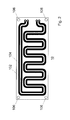
- a PCB antenna 10 is used.
- PCB antenna means an antenna comprising a support, generally a rectangular or square-shaped plate, made of insulating material, for example an epoxy resin, for example FR-4 or FR-5, and provided with one or several layers of metal, for example copper, separated by an insulating material.
- the copper layers are etched by a chemical process to obtain a set of tracks with the desired geometry.
- the PCB antenna 10 used in the system which is the subject of the invention comprises at least one conductive layer, made for example of metal or alloy, for example copper, on which is engraved a current circulation circuit which comprises at least one track for an electromagnetic signal.
- the current flow circuit comprises two tracks for two electromagnetic signals 102, 104.
- the antenna 10 has particular characteristics that allow it to be used in a pool 12 of wastewater. Indeed, it can be fixed with means 106 on the walls of the basin 12, either directly for example by screwing it with screws to the walls of the basin 12 through holes 106, or thanks to a support made with the aid of spars, as will be seen later. This antenna PCB 10 does not prevent the proper operation of cranes.
- this antenna 10 is fixed directly to the walls of the basin 12 through screws and holes 106, it is necessary to empty the basin 12 to carry out its installation or any repairs. If this antenna 10 is fixed to the walls of the basin 12 through a support made with the help of longitudinal members, it is not necessary to empty the basin 12 to carry out its installation or possible repairs: in fact one or more antennas 10 are mounted on this support made with the help of longitudinal members outside the basin 12; the support is then fixed to the walls of the basin 12 so that the part of the support containing the antennas is totally immersed and at the same time the portion of the support containing the means for fixing the support to the walls of the basin 12 is not immersed for allow this fixation. In this case the installation or possible repairs of the PCT antennas do not disturb the operation of an aeration, settling or thickening basin because it is not necessary to empty these basins to install or repair the 'antenna.
- This PCB antenna also has other characteristics for use in a basin 12: since it is designed to be totally immersed in a basin 12, it is provided with an insulating layer, for example a layer of epoxy, polyethylene or PVC over metal tracks, for example copper; this layer gives it the seal and also good mechanical strength.
- an insulating layer for example a layer of epoxy, polyethylene or PVC over metal tracks, for example copper; this layer gives it the seal and also good mechanical strength.
- the PCB antenna has large dimensions compared to known PCB antennas, for example 0.3-1.5 m by 0.3-3 m, preferably 1 m by 2.3 m. The dimensions depend on the volume and flow rate of wastewater to be treated, the depth of the basin, and the frequencies of the emitted electromagnetic signal.
- the PCB antenna has smaller dimensions, for example 0.3 m by 0.5 m, and several antennas are connected in series or in parallel so as to obtain the same effect as a single large antenna.
- the geometry of the track for the electromagnetic signal 102 may vary according to the applications; it can be optimized, for example, according to the quantity of water to be treated, depending on the basin configuration or the composition of the wastewater.
- the figure 2 illustrates a possible geometry of the tracks. In the illustrated example, two tracks are provided, one for a first signal 102 which has a frequency and the other for a second signal 104 which has a different frequency.
- the figure 3 shows another possible geometry.
- the PCB antenna 10 comprises only a conductive layer on which is etched a current circulation circuit which comprises at least one track for an electromagnetic signal (wire configuration). By increasing the length of this track, for example by connecting several antennas in series, the effect of the electromagnetic field becomes more efficient.
- another conductive layer for example copper, without etching, is placed on the surface of the antenna opposite to that comprising the tracks.
- the antenna comprises only a conductive layer, for example copper, without etching.
- the antenna comprises a wired configuration on each of the two surfaces. In this case two different frequencies are used on both surfaces.
- This antenna PCB in a variant can be connected in series with other PCB antennas of the same type fixed on the walls of the basin 12 either directly or through a support made using longitudinal members.
- One or more electromagnetic signals are sent to the track or tracks of the antenna.
- the signals, once traversed the track or tracks, are sent through cables to a track of another antenna.
- the wired length of the tracks is thus greater, which makes it possible to have a more efficient emission of electromagnetic waves in the wastewater.
- the wired length of the tracks can be a few kilometers.
- two or more PCB antennas can be connected in parallel.
- the antenna PCB 10 is linked with cables 14 to an electromagnetic signal generator 16.
- the cables are sealed and flexible, to allow their use in the open air and in the waters of the basin 12. They can be removably attached to the antennas 10, for example with connectors, to allow disassembly of the plates for their cleaning for example.
- the PCB antenna 10 is connected to the cables 14 by connectors 18, for example Binder connectors S423 or S693.
- the generator of the electromagnetic signals 16 provides at least one signal to the antenna PCB 10. In a preferred embodiment it provides two signals 102, 104. It is arranged to be able to operate in the open air with a protection index of the IP65 housing. For extreme operating conditions it can be placed in a waterproof box or inside a building.
- the signal that feeds the PCB antenna 10 has a frequency that belongs to a range that can stress the wastewater bacteria in the aeration basin, that is to say to modify their overall metabolic activity, reducing this way the quantity of sludge produced in excess or to promote their coagulation in the settling basin thanks to the reduction of the potential Zeta.
- the frequency of the signal is chosen in a range between 0 - 20000 Hz.
- the frequency is chosen in a range between 10-100 Hz in the case of a settling pond or thickening, and in a range between 2000 - 7000 Hz in the case of a ventilation tank.
- the choice of these frequency ranges is justified by tests that have been carried out and which have demonstrated, for example, a 15% greater reduction in the production of excess sludge and a reduction of the Zeta potential by 50%.
- the particular choice of the frequency or frequencies in these two ranges depends on the type of basin, the composition of the wastewater, their volume, the density of bacterial flocs, the density of bacteria, the local electromagnetic environment, etc.
- frequencies are based on equations of quantum physics which allow to determine the resonance frequencies of certain elements in a precise way, frequencies which are then reduced in the ranges chosen by successive divisions by 2.
- the frequencies thus Retentions are also chosen to be in harmonic relations with each other, that is to say with a mathematical relation between integers (for example 3/2, 4/3, etc.). It has been found experimentally that the use of a harmonic ratio improves the efficiency of the treatment.
- the final choice of frequencies is made by combining these theoretical calculations with empirical data in order to be in the optimal range.
- One of the frequencies chosen is for example that of resonance of oxygen.
- the two frequencies are chosen in one of the two ranges 10-100 Hz, 2000 - 7000 Hz with a harmonic ratio, for example a frequency can be 50 Hz and the other 75 Hz.
- the choice of the other parameters in particular the intensity of the signals 102, 104, the size of the antennas 10, the number of antennas 10, etc. This is done in particular according to the type of pond 12, volume and flow rate to be treated, sludge passage time, local electromagnetic environment, etc.
- the electromagnetic signals 102, 104 are positive pulsed continuous signals. In another variant they are alternative signals. In another variant a pulse is added on these signals.
- the output voltage of the electromagnetic signal generator 16 varies between 1 V RMS and 100 V RMS. In a variant, it varies between 5 V RMS and 50 V RMS.
- the current of the electromagnetic signal sent flows in a closed circuit. For example it is sent by the generator 16 to one or more antennas in series and then it returns to the generator 16 (loop mode).
- the current value is at most a few Amperes, for example 1 Ampere.
- the current of the electromagnetic signal sent flows in an open circuit (whip antenna).
- one or more antennas may also be used in anaerobic basins of the purification plants, with the aim of improving the efficiency of these basins and in particular of increasing the production of biogas.
- PCB antenna 10 In another variation instead of a single PCB antenna 10 of dimensions 1 m by 2.3 m, four smaller PCB antennas are used. The dimensions of these smaller antennas are for example 0.5 m by 1.150 m. In this way it is easier to stick the different layers of the PCB antennas 10, for example copper and epoxy, and to ensure a better seal of the system.
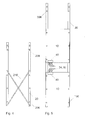
- one or more PCB antennas 10 are mounted on longitudinal members 20. As shown in FIG. figure 4 , these longitudinal members comprise holes 206 for fixing the PCB antenna or antennas 10, and holes 208 for attachment to the basin 12.
- the shape of these holes 206, 208 may be circular or any other shape.
- the distance between the holes 208, which are not immersed in the water of the basin 12 to allow a practical installation of the antennas 10, belongs to the range 15-50 cm, for example 20 cm. This range makes it possible to avoid displacements and / or oscillations of the support made using longitudinal members while guaranteeing its attachment to the walls of the basin 12.
- the support made with longitudinal members can be made stronger by means of an "X" shaped structure 210, illustrated on the figure 4 .
- this structure is not necessary, since the fixing of the antenna or antennas 10 on the side members 20 gives the support sufficient strength.
- the longitudinal members may be metallic, for example made of stainless steel. In a variant they are hollow and with a square section. Studs may be welded or crimped on the stringers 20 to secure the PCB antenna 10 through holes 106 and 206. The stringers are then attached to the walls of the pool 12 by means of bolts or screws through them. holes 208.
- One or more antennas 10 can be attached to the support of the figure 4 .
- the number of PCB antennas 10 is two, the dimensions of the support of the figure 4 will be the same as those of the support of the figure 5 .
- the figure 5 illustrates two PCB antennas 10, mounted on a support made using longitudinal members 20.
- the number of PCB antennas 10 mounted on the side members 20 may also be greater than two.
- the welds of the cables on the track or tracks of a PCB antenna 10 are protected by a resin 40, schematized on the figure 5 .
- connection cables of the antenna PCB 10 to the generator (reference 16) or to a junction box between antennas as will be seen later (reference 34) can be made of a completely waterproof material, flexible and resistant to the conditions of a basin 12. These cables may for example be made of polyethylene PE, specific manufacturing.
- the track or tracks of the PCB antenna 10 may be made of pre-oxidized metal or comprise a layer of specific varnish to protect the tracks, in order to improve the adhesion of the epoxy layers to one another, which also improves the and / or prevents the establishment of electrolytic bridges between the tracks in case liquid is allowed to penetrate.
- the epoxy thickness of the PCB antenna 10 can reach up to 0.5 mm.
- the two metal tracks for the two electromagnetic signals 102, 104 can be made either with the same layer, or with two different layers, which further prevents the establishment of electrolytic bridges between the tracks in case liquid penetrates.
- the antenna PCB 10 includes a seal on its edges to prevent the penetration of liquid on its sides. During the drying of this seal, a plastic mold can cover it to guarantee a good behavior.
- the figure 6 illustrates a possible wiring diagram of a junction box 30 of PCB antennas (not shown) according to the invention.
- the junction boxes are connected together with cables 32. They comprise means for attachment to the walls of the basin 12 not shown.
- the figure 7 illustrates a view of a junction box 30 connected to PCB antennas 10 mounted on longitudinal members. The antennas are connected to the junction boxes with cables 34 which transmit the signals 102, 104.
- junction boxes 30 After connecting the junction boxes 30 with each other, they are connected to the generator 16 of the electromagnetic signals.
- the invention also relates to a method such as that described, in which the frequency of the electromagnetic signal 102 is in the range 10-100 Hz or 2000-7000 Hz.
- the electromagnetic signals are two in number.
- the invention also relates to the use of a system for the electromagnetic treatment of wastewater comprising a basin 12 of wastewater, a generator 16 of electromagnetic signals 102, a PCB antenna 10 with an insulating layer, cables 14 fastening means 106, 20, 206, 208 of the PCB antenna 10 to the walls of the basin 12 characterized in that the generator 16 of electromagnetic signals is arranged to feed through the cables 14 with at least one electromagnetic signal 102 the antenna PCB 10, this antenna PCB 10 being fixed to the walls of the basin 12 by the fixing means 106, 20, 206, 208, the frequency of the electromagnetic signal 102 being in the range 0-20000 Hz.
- this system is used to reduce the amount of sludge produced in excess in a ventilation tank.
- this system is used to improve the settling of bacterial flocs in a pond 12 of settling or thickening.
Applications Claiming Priority (1)
| Application Number | Priority Date | Filing Date | Title |
|---|---|---|---|
| CH00206/10A CH702742A1 (fr) | 2010-02-19 | 2010-02-19 | Dispositif et procédé pour le traitement électromagnétique des eaux usées. |
Publications (2)
| Publication Number | Publication Date |
|---|---|
| EP2364954A1 true EP2364954A1 (de) | 2011-09-14 |
| EP2364954B1 EP2364954B1 (de) | 2018-07-04 |
Family
ID=42244966
Family Applications (1)
| Application Number | Title | Priority Date | Filing Date |
|---|---|---|---|
| EP11152231.4A Active EP2364954B1 (de) | 2010-02-19 | 2011-01-26 | System und Verfahren zur elektromagnetischen Aufbereitung von Abwasser |
Country Status (2)
| Country | Link |
|---|---|
| EP (1) | EP2364954B1 (de) |
| CH (1) | CH702742A1 (de) |
Cited By (1)
| Publication number | Priority date | Publication date | Assignee | Title |
|---|---|---|---|---|
| EP2848591A1 (de) | 2013-09-09 | 2015-03-18 | Paul Van Welden | Verfahren und Vorrichtung zur Behandlung von Fluiden mit Hilfe von elektrischer Induktion |
Families Citing this family (1)
| Publication number | Priority date | Publication date | Assignee | Title |
|---|---|---|---|---|
| EP4015461A1 (de) | 2020-12-18 | 2022-06-22 | BE WTR Sàrl | Wasseraktivierungsvorrichtung und behälter |
Citations (6)
| Publication number | Priority date | Publication date | Assignee | Title |
|---|---|---|---|---|
| DE3836155A1 (de) * | 1988-10-24 | 1990-04-26 | Hans Dr Weiers | Elektrodenvorrichtung fuer hochfrequenzelektroden |
| WO2000033954A1 (en) | 1998-12-11 | 2000-06-15 | Howard Thomason | Methods of preparing and using electrostatically treated fluids |
| GB2398295A (en) | 2003-02-15 | 2004-08-18 | Hotta Uk Ltd | An electronic de-scaler |
| US20050121396A1 (en) | 2003-12-09 | 2005-06-09 | Kosakewich Darrell S. | Apparatus and method for treating substances with electromagnetic wave energy |
| EP1676815A1 (de) * | 2004-12-28 | 2006-07-05 | Planet Horizons Technologies SA | Elektromagnetischer Behandlungsprozess für Flüssigkeiten |
| US20090301188A1 (en) * | 2008-06-09 | 2009-12-10 | Luna Labs, Inc. | Self-Calibrating Capacitive Transducer for Determining Level of Fluent Materials |
-
2010
- 2010-02-19 CH CH00206/10A patent/CH702742A1/fr not_active Application Discontinuation
-
2011
- 2011-01-26 EP EP11152231.4A patent/EP2364954B1/de active Active
Patent Citations (6)
| Publication number | Priority date | Publication date | Assignee | Title |
|---|---|---|---|---|
| DE3836155A1 (de) * | 1988-10-24 | 1990-04-26 | Hans Dr Weiers | Elektrodenvorrichtung fuer hochfrequenzelektroden |
| WO2000033954A1 (en) | 1998-12-11 | 2000-06-15 | Howard Thomason | Methods of preparing and using electrostatically treated fluids |
| GB2398295A (en) | 2003-02-15 | 2004-08-18 | Hotta Uk Ltd | An electronic de-scaler |
| US20050121396A1 (en) | 2003-12-09 | 2005-06-09 | Kosakewich Darrell S. | Apparatus and method for treating substances with electromagnetic wave energy |
| EP1676815A1 (de) * | 2004-12-28 | 2006-07-05 | Planet Horizons Technologies SA | Elektromagnetischer Behandlungsprozess für Flüssigkeiten |
| US20090301188A1 (en) * | 2008-06-09 | 2009-12-10 | Luna Labs, Inc. | Self-Calibrating Capacitive Transducer for Determining Level of Fluent Materials |
Cited By (2)
| Publication number | Priority date | Publication date | Assignee | Title |
|---|---|---|---|---|
| EP2848591A1 (de) | 2013-09-09 | 2015-03-18 | Paul Van Welden | Verfahren und Vorrichtung zur Behandlung von Fluiden mit Hilfe von elektrischer Induktion |
| BE1022086B1 (nl) * | 2013-09-09 | 2016-02-15 | Van Welden, Paul | Werkwijze en toestel voor het behandelen van fluida |
Also Published As
| Publication number | Publication date |
|---|---|
| CH702742A1 (fr) | 2011-08-31 |
| EP2364954B1 (de) | 2018-07-04 |
Similar Documents
| Publication | Publication Date | Title |
|---|---|---|
| Seyfried et al. | Potential local environmental impacts of salinity gradient energy: A review | |
| CN101503221B (zh) | 一种具有防海生物污损功能的装置 | |
| EP3079840B1 (de) | Geoverbundstoff für bodenbehandlung, bodenbehandlungssystem und bodenverfestigungsverfahren mit solchem geoverbundstoff. | |
| EP2364954B1 (de) | System und Verfahren zur elektromagnetischen Aufbereitung von Abwasser | |
| CN202849188U (zh) | 超声电絮凝沉淀一体化装置 | |
| FR2832703A1 (fr) | Dispositif sono-electrochimique et procede sono-electrochimique de degradation de molecules organiques | |
| FR2707282A1 (fr) | Cellule d'électrocoagulation pour dispositif d'épuration électrolytique des eaux résiduaires. | |
| EP0152336B1 (de) | Verfahren zur Ausrichtung und zur Beschleunigung der Bildung von Ablagerungen in Meerwasser und Vorrichtung zur Durchfürung des Verfahrens | |
| EP1592611A1 (de) | Bewuchsverhinderungs- und -beseitigungssystem gegen wasserorganismen | |
| EP3080050A1 (de) | System und verfahren zur elektrochemischen in-situ-behandlung, zur erfassung von schadstoffen und ablagerungen sowie zur reinigung verunreinigten stellen im meer | |
| US20100095847A1 (en) | System for conditioning fluids utilizing a magnetic fluid processor | |
| Lattemann et al. | Seawater desalination—a green technology? | |
| EP1676815A1 (de) | Elektromagnetischer Behandlungsprozess für Flüssigkeiten | |
| US20200148557A1 (en) | method to control micro algae growth and mitigation of microcystins | |
| JP2004137593A (ja) | 多孔質体セラミックス水電極板 | |
| US20070077166A1 (en) | Method, installation and component for destruction of live organisms in a liquid | |
| JP2003080260A (ja) | 水質或いは土質改善方法及び装置 | |
| CN102616883A (zh) | 污水预处理器和污水预处理装置 | |
| Dineva | Water discharges into the Bulgarian Black Sea | |
| KR20170049792A (ko) | 수중 침지 방식의 조류 제거 장치 | |
| FR2539146A1 (fr) | Concretionnement mineral des structures, composants et elements de construction | |
| KR20150135158A (ko) | 폐수로부터 금속의 추출 및 회수 처리장치 | |
| RU2301199C1 (ru) | Способ обработки воды | |
| Purnama | Analytical model for brine discharges from a sea outfall with multiport diffusers | |
| BE1004165A7 (fr) | Procede et installation physico-chimiques pour le traitement et l'epuration des eaux usees. |
Legal Events
| Date | Code | Title | Description |
|---|---|---|---|
| PUAI | Public reference made under article 153(3) epc to a published international application that has entered the european phase |
Free format text: ORIGINAL CODE: 0009012 |
|
| AK | Designated contracting states |
Kind code of ref document: A1 Designated state(s): AL AT BE BG CH CY CZ DE DK EE ES FI FR GB GR HR HU IE IS IT LI LT LU LV MC MK MT NL NO PL PT RO RS SE SI SK SM TR |
|
| AX | Request for extension of the european patent |
Extension state: BA ME |
|
| 17P | Request for examination filed |
Effective date: 20120314 |
|
| 17Q | First examination report despatched |
Effective date: 20140606 |
|
| STAA | Information on the status of an ep patent application or granted ep patent |
Free format text: STATUS: EXAMINATION IS IN PROGRESS |
|
| GRAP | Despatch of communication of intention to grant a patent |
Free format text: ORIGINAL CODE: EPIDOSNIGR1 |
|
| STAA | Information on the status of an ep patent application or granted ep patent |
Free format text: STATUS: GRANT OF PATENT IS INTENDED |
|
| INTG | Intention to grant announced |
Effective date: 20180202 |
|
| GRAS | Grant fee paid |
Free format text: ORIGINAL CODE: EPIDOSNIGR3 |
|
| GRAA | (expected) grant |
Free format text: ORIGINAL CODE: 0009210 |
|
| STAA | Information on the status of an ep patent application or granted ep patent |
Free format text: STATUS: THE PATENT HAS BEEN GRANTED |
|
| AK | Designated contracting states |
Kind code of ref document: B1 Designated state(s): AL AT BE BG CH CY CZ DE DK EE ES FI FR GB GR HR HU IE IS IT LI LT LU LV MC MK MT NL NO PL PT RO RS SE SI SK SM TR |
|
| REG | Reference to a national code |
Ref country code: GB Ref legal event code: FG4D Free format text: NOT ENGLISH |
|
| REG | Reference to a national code |
Ref country code: CH Ref legal event code: EP |
|
| REG | Reference to a national code |
Ref country code: AT Ref legal event code: REF Ref document number: 1014308 Country of ref document: AT Kind code of ref document: T Effective date: 20180715 |
|
| REG | Reference to a national code |
Ref country code: IE Ref legal event code: FG4D Free format text: LANGUAGE OF EP DOCUMENT: FRENCH |
|
| REG | Reference to a national code |
Ref country code: DE Ref legal event code: R096 Ref document number: 602011049680 Country of ref document: DE |
|
| REG | Reference to a national code |
Ref country code: NL Ref legal event code: MP Effective date: 20180704 |
|
| REG | Reference to a national code |
Ref country code: LT Ref legal event code: MG4D |
|
| REG | Reference to a national code |
Ref country code: AT Ref legal event code: MK05 Ref document number: 1014308 Country of ref document: AT Kind code of ref document: T Effective date: 20180704 |
|
| PG25 | Lapsed in a contracting state [announced via postgrant information from national office to epo] |
Ref country code: NL Free format text: LAPSE BECAUSE OF FAILURE TO SUBMIT A TRANSLATION OF THE DESCRIPTION OR TO PAY THE FEE WITHIN THE PRESCRIBED TIME-LIMIT Effective date: 20180704 |
|
| PG25 | Lapsed in a contracting state [announced via postgrant information from national office to epo] |
Ref country code: RS Free format text: LAPSE BECAUSE OF FAILURE TO SUBMIT A TRANSLATION OF THE DESCRIPTION OR TO PAY THE FEE WITHIN THE PRESCRIBED TIME-LIMIT Effective date: 20180704 Ref country code: LT Free format text: LAPSE BECAUSE OF FAILURE TO SUBMIT A TRANSLATION OF THE DESCRIPTION OR TO PAY THE FEE WITHIN THE PRESCRIBED TIME-LIMIT Effective date: 20180704 Ref country code: AT Free format text: LAPSE BECAUSE OF FAILURE TO SUBMIT A TRANSLATION OF THE DESCRIPTION OR TO PAY THE FEE WITHIN THE PRESCRIBED TIME-LIMIT Effective date: 20180704 Ref country code: IS Free format text: LAPSE BECAUSE OF FAILURE TO SUBMIT A TRANSLATION OF THE DESCRIPTION OR TO PAY THE FEE WITHIN THE PRESCRIBED TIME-LIMIT Effective date: 20181104 Ref country code: PL Free format text: LAPSE BECAUSE OF FAILURE TO SUBMIT A TRANSLATION OF THE DESCRIPTION OR TO PAY THE FEE WITHIN THE PRESCRIBED TIME-LIMIT Effective date: 20180704 Ref country code: GR Free format text: LAPSE BECAUSE OF FAILURE TO SUBMIT A TRANSLATION OF THE DESCRIPTION OR TO PAY THE FEE WITHIN THE PRESCRIBED TIME-LIMIT Effective date: 20181005 Ref country code: FI Free format text: LAPSE BECAUSE OF FAILURE TO SUBMIT A TRANSLATION OF THE DESCRIPTION OR TO PAY THE FEE WITHIN THE PRESCRIBED TIME-LIMIT Effective date: 20180704 Ref country code: SE Free format text: LAPSE BECAUSE OF FAILURE TO SUBMIT A TRANSLATION OF THE DESCRIPTION OR TO PAY THE FEE WITHIN THE PRESCRIBED TIME-LIMIT Effective date: 20180704 Ref country code: NO Free format text: LAPSE BECAUSE OF FAILURE TO SUBMIT A TRANSLATION OF THE DESCRIPTION OR TO PAY THE FEE WITHIN THE PRESCRIBED TIME-LIMIT Effective date: 20181004 Ref country code: CZ Free format text: LAPSE BECAUSE OF FAILURE TO SUBMIT A TRANSLATION OF THE DESCRIPTION OR TO PAY THE FEE WITHIN THE PRESCRIBED TIME-LIMIT Effective date: 20180704 Ref country code: BG Free format text: LAPSE BECAUSE OF FAILURE TO SUBMIT A TRANSLATION OF THE DESCRIPTION OR TO PAY THE FEE WITHIN THE PRESCRIBED TIME-LIMIT Effective date: 20181004 |
|
| PG25 | Lapsed in a contracting state [announced via postgrant information from national office to epo] |
Ref country code: ES Free format text: LAPSE BECAUSE OF FAILURE TO SUBMIT A TRANSLATION OF THE DESCRIPTION OR TO PAY THE FEE WITHIN THE PRESCRIBED TIME-LIMIT Effective date: 20180704 Ref country code: LV Free format text: LAPSE BECAUSE OF FAILURE TO SUBMIT A TRANSLATION OF THE DESCRIPTION OR TO PAY THE FEE WITHIN THE PRESCRIBED TIME-LIMIT Effective date: 20180704 Ref country code: HR Free format text: LAPSE BECAUSE OF FAILURE TO SUBMIT A TRANSLATION OF THE DESCRIPTION OR TO PAY THE FEE WITHIN THE PRESCRIBED TIME-LIMIT Effective date: 20180704 Ref country code: AL Free format text: LAPSE BECAUSE OF FAILURE TO SUBMIT A TRANSLATION OF THE DESCRIPTION OR TO PAY THE FEE WITHIN THE PRESCRIBED TIME-LIMIT Effective date: 20180704 |
|
| REG | Reference to a national code |
Ref country code: DE Ref legal event code: R097 Ref document number: 602011049680 Country of ref document: DE |
|
| PG25 | Lapsed in a contracting state [announced via postgrant information from national office to epo] |
Ref country code: IT Free format text: LAPSE BECAUSE OF FAILURE TO SUBMIT A TRANSLATION OF THE DESCRIPTION OR TO PAY THE FEE WITHIN THE PRESCRIBED TIME-LIMIT Effective date: 20180704 Ref country code: RO Free format text: LAPSE BECAUSE OF FAILURE TO SUBMIT A TRANSLATION OF THE DESCRIPTION OR TO PAY THE FEE WITHIN THE PRESCRIBED TIME-LIMIT Effective date: 20180704 Ref country code: EE Free format text: LAPSE BECAUSE OF FAILURE TO SUBMIT A TRANSLATION OF THE DESCRIPTION OR TO PAY THE FEE WITHIN THE PRESCRIBED TIME-LIMIT Effective date: 20180704 |
|
| PLBE | No opposition filed within time limit |
Free format text: ORIGINAL CODE: 0009261 |
|
| STAA | Information on the status of an ep patent application or granted ep patent |
Free format text: STATUS: NO OPPOSITION FILED WITHIN TIME LIMIT |
|
| PG25 | Lapsed in a contracting state [announced via postgrant information from national office to epo] |
Ref country code: DK Free format text: LAPSE BECAUSE OF FAILURE TO SUBMIT A TRANSLATION OF THE DESCRIPTION OR TO PAY THE FEE WITHIN THE PRESCRIBED TIME-LIMIT Effective date: 20180704 Ref country code: SK Free format text: LAPSE BECAUSE OF FAILURE TO SUBMIT A TRANSLATION OF THE DESCRIPTION OR TO PAY THE FEE WITHIN THE PRESCRIBED TIME-LIMIT Effective date: 20180704 Ref country code: SM Free format text: LAPSE BECAUSE OF FAILURE TO SUBMIT A TRANSLATION OF THE DESCRIPTION OR TO PAY THE FEE WITHIN THE PRESCRIBED TIME-LIMIT Effective date: 20180704 |
|
| 26N | No opposition filed |
Effective date: 20190405 |
|
| PG25 | Lapsed in a contracting state [announced via postgrant information from national office to epo] |
Ref country code: SI Free format text: LAPSE BECAUSE OF FAILURE TO SUBMIT A TRANSLATION OF THE DESCRIPTION OR TO PAY THE FEE WITHIN THE PRESCRIBED TIME-LIMIT Effective date: 20180704 Ref country code: MC Free format text: LAPSE BECAUSE OF FAILURE TO SUBMIT A TRANSLATION OF THE DESCRIPTION OR TO PAY THE FEE WITHIN THE PRESCRIBED TIME-LIMIT Effective date: 20180704 |
|
| REG | Reference to a national code |
Ref country code: CH Ref legal event code: PL |
|
| PG25 | Lapsed in a contracting state [announced via postgrant information from national office to epo] |
Ref country code: LU Free format text: LAPSE BECAUSE OF NON-PAYMENT OF DUE FEES Effective date: 20190126 |
|
| REG | Reference to a national code |
Ref country code: BE Ref legal event code: MM Effective date: 20190131 |
|
| REG | Reference to a national code |
Ref country code: IE Ref legal event code: MM4A |
|
| PG25 | Lapsed in a contracting state [announced via postgrant information from national office to epo] |
Ref country code: BE Free format text: LAPSE BECAUSE OF NON-PAYMENT OF DUE FEES Effective date: 20190131 |
|
| PG25 | Lapsed in a contracting state [announced via postgrant information from national office to epo] |
Ref country code: CH Free format text: LAPSE BECAUSE OF NON-PAYMENT OF DUE FEES Effective date: 20190131 Ref country code: LI Free format text: LAPSE BECAUSE OF NON-PAYMENT OF DUE FEES Effective date: 20190131 |
|
| PG25 | Lapsed in a contracting state [announced via postgrant information from national office to epo] |
Ref country code: IE Free format text: LAPSE BECAUSE OF NON-PAYMENT OF DUE FEES Effective date: 20190126 |
|
| REG | Reference to a national code |
Ref country code: DE Ref legal event code: R082 Ref document number: 602011049680 Country of ref document: DE Representative=s name: BECK & ROESSIG EUROPEAN PATENT ATTORNEYS, DE Ref country code: DE Ref legal event code: R082 Ref document number: 602011049680 Country of ref document: DE Representative=s name: BECK & ROESSIG - EUROPEAN PATENT ATTORNEYS, DE |
|
| PG25 | Lapsed in a contracting state [announced via postgrant information from national office to epo] |
Ref country code: TR Free format text: LAPSE BECAUSE OF FAILURE TO SUBMIT A TRANSLATION OF THE DESCRIPTION OR TO PAY THE FEE WITHIN THE PRESCRIBED TIME-LIMIT Effective date: 20180704 |
|
| PG25 | Lapsed in a contracting state [announced via postgrant information from national office to epo] |
Ref country code: PT Free format text: LAPSE BECAUSE OF FAILURE TO SUBMIT A TRANSLATION OF THE DESCRIPTION OR TO PAY THE FEE WITHIN THE PRESCRIBED TIME-LIMIT Effective date: 20181105 Ref country code: MT Free format text: LAPSE BECAUSE OF FAILURE TO SUBMIT A TRANSLATION OF THE DESCRIPTION OR TO PAY THE FEE WITHIN THE PRESCRIBED TIME-LIMIT Effective date: 20180704 |
|
| PG25 | Lapsed in a contracting state [announced via postgrant information from national office to epo] |
Ref country code: CY Free format text: LAPSE BECAUSE OF FAILURE TO SUBMIT A TRANSLATION OF THE DESCRIPTION OR TO PAY THE FEE WITHIN THE PRESCRIBED TIME-LIMIT Effective date: 20180704 |
|
| PG25 | Lapsed in a contracting state [announced via postgrant information from national office to epo] |
Ref country code: HU Free format text: LAPSE BECAUSE OF FAILURE TO SUBMIT A TRANSLATION OF THE DESCRIPTION OR TO PAY THE FEE WITHIN THE PRESCRIBED TIME-LIMIT; INVALID AB INITIO Effective date: 20110126 |
|
| PG25 | Lapsed in a contracting state [announced via postgrant information from national office to epo] |
Ref country code: MK Free format text: LAPSE BECAUSE OF FAILURE TO SUBMIT A TRANSLATION OF THE DESCRIPTION OR TO PAY THE FEE WITHIN THE PRESCRIBED TIME-LIMIT Effective date: 20180704 |
|
| PGFP | Annual fee paid to national office [announced via postgrant information from national office to epo] |
Ref country code: FR Payment date: 20230124 Year of fee payment: 13 |
|
| PGFP | Annual fee paid to national office [announced via postgrant information from national office to epo] |
Ref country code: DE Payment date: 20240119 Year of fee payment: 14 Ref country code: GB Payment date: 20240119 Year of fee payment: 14 |