EP2363308B1 - Achslenker für eine luftgefederte Fahrzeugachse - Google Patents
Achslenker für eine luftgefederte Fahrzeugachse Download PDFInfo
- Publication number
- EP2363308B1 EP2363308B1 EP11156353.2A EP11156353A EP2363308B1 EP 2363308 B1 EP2363308 B1 EP 2363308B1 EP 11156353 A EP11156353 A EP 11156353A EP 2363308 B1 EP2363308 B1 EP 2363308B1
- Authority
- EP
- European Patent Office
- Prior art keywords
- axle guide
- axle
- fastening holes
- wishbone
- air spring
- Prior art date
- Legal status (The legal status is an assumption and is not a legal conclusion. Google has not performed a legal analysis and makes no representation as to the accuracy of the status listed.)
- Active
Links
Images
Classifications
-
- B—PERFORMING OPERATIONS; TRANSPORTING
- B60—VEHICLES IN GENERAL
- B60G—VEHICLE SUSPENSION ARRANGEMENTS
- B60G11/00—Resilient suspensions characterised by arrangement, location or kind of springs
- B60G11/26—Resilient suspensions characterised by arrangement, location or kind of springs having fluid springs only, e.g. hydropneumatic springs
- B60G11/28—Resilient suspensions characterised by arrangement, location or kind of springs having fluid springs only, e.g. hydropneumatic springs characterised by means specially adapted for attaching the spring to axle or sprung part of the vehicle
-
- B—PERFORMING OPERATIONS; TRANSPORTING
- B60—VEHICLES IN GENERAL
- B60G—VEHICLE SUSPENSION ARRANGEMENTS
- B60G11/00—Resilient suspensions characterised by arrangement, location or kind of springs
- B60G11/32—Resilient suspensions characterised by arrangement, location or kind of springs having springs of different kinds
- B60G11/34—Resilient suspensions characterised by arrangement, location or kind of springs having springs of different kinds including leaf springs
- B60G11/46—Resilient suspensions characterised by arrangement, location or kind of springs having springs of different kinds including leaf springs and also fluid springs
- B60G11/465—Resilient suspensions characterised by arrangement, location or kind of springs having springs of different kinds including leaf springs and also fluid springs with a flexible wall
-
- B—PERFORMING OPERATIONS; TRANSPORTING
- B60—VEHICLES IN GENERAL
- B60G—VEHICLE SUSPENSION ARRANGEMENTS
- B60G9/00—Resilient suspensions of a rigid axle or axle housing for two or more wheels
- B60G9/003—Resilient suspensions of a rigid axle or axle housing for two or more wheels the axle being rigidly connected to a trailing guiding device
-
- B—PERFORMING OPERATIONS; TRANSPORTING
- B60—VEHICLES IN GENERAL
- B60G—VEHICLE SUSPENSION ARRANGEMENTS
- B60G2200/00—Indexing codes relating to suspension types
- B60G2200/30—Rigid axle suspensions
- B60G2200/31—Rigid axle suspensions with two trailing arms rigidly connected to the axle
-
- B—PERFORMING OPERATIONS; TRANSPORTING
- B60—VEHICLES IN GENERAL
- B60G—VEHICLE SUSPENSION ARRANGEMENTS
- B60G2202/00—Indexing codes relating to the type of spring, damper or actuator
- B60G2202/10—Type of spring
- B60G2202/15—Fluid spring
- B60G2202/152—Pneumatic spring
-
- B—PERFORMING OPERATIONS; TRANSPORTING
- B60—VEHICLES IN GENERAL
- B60G—VEHICLE SUSPENSION ARRANGEMENTS
- B60G2204/00—Indexing codes related to suspensions per se or to auxiliary parts
- B60G2204/10—Mounting of suspension elements
- B60G2204/12—Mounting of springs or dampers
- B60G2204/126—Mounting of pneumatic springs
-
- B—PERFORMING OPERATIONS; TRANSPORTING
- B60—VEHICLES IN GENERAL
- B60G—VEHICLE SUSPENSION ARRANGEMENTS
- B60G2204/00—Indexing codes related to suspensions per se or to auxiliary parts
- B60G2204/40—Auxiliary suspension parts; Adjustment of suspensions
- B60G2204/44—Centering or positioning means
-
- B—PERFORMING OPERATIONS; TRANSPORTING
- B60—VEHICLES IN GENERAL
- B60G—VEHICLE SUSPENSION ARRANGEMENTS
- B60G2206/00—Indexing codes related to the manufacturing of suspensions: constructional features, the materials used, procedures or tools
- B60G2206/01—Constructional features of suspension elements, e.g. arms, dampers, springs
- B60G2206/10—Constructional features of arms
- B60G2206/11—Constructional features of arms the arm being a radius or track or torque or steering rod or stabiliser end link
Definitions
- the invention relates to a wishbone for an air-suspension vehicle axle, with a Achseinitatis Grade, a pivot bearing at one end of the wishbone and consisting of at least two mounting holes hole pattern for attachment of different air springs and / or an air spring in different positions at the other end of the axle guide.
- the air spring In air-suspended vehicle axles, the air spring is usually connected to the wishbone in a fixed, immovable position. Frequently, the parts are also welded together, whereby a subsequent change in position of the air spring in relation to the wishbone is not possible.
- a wishbone with the features of the preamble is from the EP 0 830 959 B1 known.
- the wishbone is provided in its rear area with a plurality of distributed over the length and width of the wishbone arranged holes.
- the position of one and the same air spring is variable with respect to their distance from the chassis-fixed bearing point of the axle guide, and with respect to their distance from the vehicle longitudinal center plane. In this way, the wishbone with air springs of different manufacturers and different Connection dimensions combine, which has the advantage of a smaller product variety and thus reduced storage.
- the aim of the invention are technical measures to one and the same Achslenkerbautyp for different, eg. B. make custom installation situations suitable so as to come from the manufacturer to a reduced product variety and thus a reduced storage.
- the aim is also a confusion-safe air spring mounting, by a specific for the axle control air spring is indeed mounted in the intended position or intended positions, but not in other, also provided by the wishbone positions.
- a wishbone with the features of claim 1. This is characterized by at least one first mounting hole, and at least one purpose a different diameter exhibiting, second mounting hole.
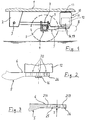
- the Fig. 1 shows a side view of a bogie, as is commonly used in heavy-duty vehicles and in particular commercial vehicle trailers with non-driven axle.
- a support 2 is fixed on each side of the vehicle with a pivot joint 3 for articulated connection with the front end of each Achslenkers 5.
- the axis 4, at the outer ends of the vehicle wheels are mounted, extending transversely to the direction of travel. Near its two ends, the axle 4 is connected in each case to a trailing arm designed as a fifth link 5.
- the wishbone 5 a Achseinitatis Scheme 7, in which, for. B. by means of corresponding connecting elements 9, the wishbone 5 is connected to the axle body 4.
- the axle of the axle 4 is designed here as axle tube with a rectangular cross section, as well as the axle body z. B. have a round cross-section.
- the wishbone 5 is designed as a link spring, and consists of a deformable spring steel.
- an air spring 10 is attached, on the other hand is supported from below against the chassis 1, and so on the wishbone 5, the vehicle axle springs.
- the air spring 10 is composed in a conventional manner from a flexible, the pressure chamber forming bellows 11, a supported on the upper side 6 of the axle guide 5 plunger 12 and a lid 13 as the upper end of the Rollbalgvolumens together.
- the structure of such an air spring with plunger is z. B. from the DE 197 10 849 A1 known.
- Fig. 2 the attachment of the plunger 12 of the air spring on the upper side 6 of the axle guide 5 by means of one or more passing through holes of the axle guide 5 screws 16, 17.
- the screw engages with its thread in a corresponding thread of the plunger 12, and it is supported her screw head from below against the wishbone 5 from.
- For passing the screw 16, 17 through the wishbone serves a corresponding mounting hole, which, as will be shown in detail below, not only a single mounting hole is present, but a plurality of mounting holes, which together a hole pattern 20 on the rear longitudinal portion of the axle guide 5 form. On this rear longitudinal section and thus in the area of the hole pattern 20, the axle guide 5 has a greater width than on its remaining length.
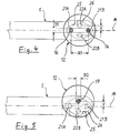
- the hole pattern 20 is diamond-shaped and consists of a total of four mounting holes 21A, 21B, 22A, 22B together.
- Two mounting holes 21A, 21B are located on the longitudinal center line M of the axle guide 5. They have a hole spacing A1 to each other.
- Both mounting holes 21 A, 21 B are designed as equal holes with a diameter D1, the z. B. 17 mm.
- To the hole pattern 20 also includes two further mounting holes 22A, 22B, which are located on the same longitudinal portion of the axle guide, said longitudinal portion is located at the center of the distance A1 between the other two mounting holes 21A, 21B.
- the mounting holes 22A, 22B are respectively on different sides with respect to the longitudinal center line M, and therefore have to this in each case an offset V, the z. B. is 20 mm, respectively.
- the diameter D2 of both mounting holes 22A, 22B is identical, but is different from the diameter D1 of the other mounting holes and is e.g. B. 18.5 mm.
- Fig. 4 shows a first way to attach an air spring with its plunger 12 on the axle guide 5.
- the attachment takes place here by means of two screws 16 which are passed through the arranged on the longitudinal center line M mounting holes 21A, 21B. This leads to a symmetrical positioning of the air spring with respect to the longitudinal center line M.
- the Fig. 5 shows in contrast another possible mounting position.
- the attachment of the plunger 12 is carried out here with only one screw 17, which is located exactly on the central axis of a circular base having air spring.
- the screw 17 is passed through the arranged with lateral offset V mounting hole 22 A, whereby the air spring has an offset V to the longitudinal center line M of the axle guide 5.
- the same or a different design air spring could also be mounted on the other side mounting hole 22B, which would also offset the air spring, but to the other side, achieved.
- the diameter D2 of the mounting holes 22A, 22B is greater than the diameter D1 of the mounting holes 21A, 21B.
- the axle guide 5 is provided on its underside in the area around the mounting holes 21A, 21B, 22A, 22B around with a recess 25 around which still remains a downwardly projecting edge 26.
- the recess 25 is here diamond-shaped and of such extent and depth T, that the head of the screw 16, 17 disappears in part in the recess 25.
- the depression 25 can be e.g. make by plan milling. In this way, the bottom of the depression forms a flat surface on which the screw head, even without a washer, can be defined and supported without jamming.
- resulting mounting holes 21A, 21B, 22A, 22B can therefore be differently shaped air springs and / or attach with different connection dimensions on the upper side of the axle guide, or it can be one and the same air spring in more than one position fasten.
Landscapes
- Engineering & Computer Science (AREA)
- Mechanical Engineering (AREA)
- Vehicle Body Suspensions (AREA)
- Fluid-Damping Devices (AREA)
Description
- Die Erfindung betrifft einen Achslenker für eine luftgefederte Fahrzeugachse, mit einem Achseinbindungsbereich, einem Schwenklager am einen Ende des Achslenkers sowie einem aus mindestens zwei Befestigungslöchern bestehenden Lochbild zur Befestigung unterschiedlicher Luftfedern und/oder einer Luftfeder in unterschiedlichen Positionen am anderen Ende des Achslenkers.
- Bei luftgefederten Fahrzeugachsen ist die Luftfeder zumeist mit dem Achslenker in fester, unveränderlicher Position verbunden. Häufig sind die Teile auch miteinander verschweißt, wodurch eine nachträgliche Positionsänderung der Luftfeder in Bezug auf den Achslenker nicht möglich ist.
- Aus der
DE 42 24 965 C1 ist es bekannt, den Achslenker zur wahlweisen Befestigung unterschiedlich dimensionierter Luftfedern mit insgesamt drei Löchern gleichen Durchmessers zu versehen, die in Reihe, aber mit ungleichen Abständen angeordnet sind. Die Befestigung der jeweiligen Luftfeder erfolgt über zwei dieser drei Löcher. - Aus der
DE 42 13 676 A1 ist es bekannt, eine aus einem Luftfederbalg und einem Tauchkolben bestehende Luftfeder auf einfache Weise in verschiedenen Positionen an einem Achslenker zu befestigen. Hierzu weist der Tauchkolben der Luftfeder eine nach unten offene Aufnahmeöffnung auf, in die ein Befestigungsteil von unten her einschiebbar ist. Dieses weist zur Seite hin einen Befestigungsansatz auf, über den das Befestigungsteil an dem Achslenker montiert werden kann. Auf diese Weise ist der Tauchkolben z. B. in zwei um 180° um die Längsachse gedrehten Positionen an dem Achslenker befestigbar, so dass sich ein unterschiedlicher seitlicher Versatz der Luftfeder in Bezug auf den Achslenker einstellen lässt. - Ein Achslenker mit den Merkmalen des Oberbegriffs ist aus der
EP 0 830 959 B1 bekannt. Der Achslenker ist in seinem hinteren Bereich mit einer Vielzahl über Länge und Breite des Achslenkers verteilt angeordneter Löcher versehen. Die Position ein- und derselben Luftfeder ist hinsichtlich ihres Abstandes von dem chassisfesten Lagerpunkt des Achslenkers, und hinsichtlich ihres Abstandes von der Fahrzeuglängsmittelebene veränderbar. Auf diese Weise lässt sich der Achslenker mit Luftfedern verschiedener Hersteller und unterschiedlichen Anschlussmaßen kombinieren, was den Vorteil einer geringeren Produktvielfalt und damit reduzierter Lagerhaltung hat. - Ziel der Erfindung sind technische Maßnahmen, um ein- und denselben Achslenkerbautyp für unterschiedliche, z. B. kundenspezifische Einbausituationen geeignet zu machen, um so herstellerseitig zu einer verringerten Produktvielfalt und damit einer reduzierten Lagerhaltung zu kommen. Ziel ist ferner eine verwechslungssichere Luftfedermontage, indem eine für den Achslenker bestimmte Luftfeder zwar in vorgesehener Position oder vorgesehenen Positionen, nicht jedoch in anderen, durch den Achslenker ebenfalls bereitgestellten Positionen montierbar ist.
- Erreicht wird dieses Ziel durch einen Achslenker mit den Merkmalen des Anspruchs 1. Dieser ist gekennzeichnet durch mindestens ein erstes Befestigungsloch, sowie mindestens ein hierzu einen unterschiedlichen Durchmesser aufweisendes, zweites Befestigungsloch.
- An einem solcherart gestalteten Achslenker lassen sich ohne die Gefahr von Fehlmontagen Luftfedern mit gleichen oder unterschiedlichen Anschlussmaßen einsetzen, und selbst ein- und derselbe Achslenkerbautyp ist für unterschiedliche kundenspezifische Einbausituationen geeignet. Der Vorteil für einen Hersteller von Fahrwerken liegt in der verringerten Produktvielfalt, verbunden mit dem Vorteil einer reduzierten Lagerhaltung, da eine geringere Anzahl an Bautypen vorrätig gehalten werden muss.
- Vorteilhafte Ausgestaltungen des erfindungsgemäßen Achslenkers sind in den Unteransprüchen angegeben.
- Nachfolgend werden anhand der Zeichnungen besondere Ausgestaltungen der Erfindung näher erläutert. Auf der Zeichnung zeigen:
- Fig. 1
- in einer vereinfachten Seitenansicht ein Achsaggregat eines luftgefederten Fahrzeuges einschließlich eines Achskörpers, eines Achslenkers und einer den Achslenker gegenüber dem Fahrzeugchassis abstützenden Luftfeder;
- Fig. 2
- in vergrößerter Darstellung die Einzelheit II der
Fig. 1 ; - Fig. 3
- einen Längsschnitt durch den hinteren Teil des Achslenkers, wobei die Luftfeder nicht dargestellt ist;
- Fig. 4
- in einer Draufsicht eine erste Möglichkeit der Positionierung einer Luftfeder auf dem hinteren Teil des Achslenkers und
- Fig. 5
- ebenfalls in einer Draufsicht eine zweite Möglichkeit einer Positionierung einer Luftfeder auf dem hinteren Teil des Achslenkers.
- Die
Fig. 1 zeigt in Seitenansicht ein Achsaggregat, wie es üblicherweise bei Schwerlastfahrzeugen und insbesondere Nutzfahrzeuganhängern mit nicht angetriebener Achse zum Einsatz kommt. Unter dem Chassis 1 des Fahrzeuges ist auf jeder Fahrzeugseite eine Stütze 2 mit einem Schwenkgelenk 3 für eine gelenkige Verbindung mit dem vorderen Ende jeweils eines Achslenkers 5 befestigt. Die Achse 4, an deren äußeren Enden die Fahrzeugräder gelagert sind, erstreckt sich quer zur Fahrtrichtung. Nahe ihrer beiden Enden ist die Achse 4 jeweils mit einem als Längslenker gestalteten Achslenker 5 verbunden. Hierzu weist der Achslenker 5 einen Achseinbindungsbereich 7 auf, in dem, z. B. mittels entsprechender Verbindungselemente 9, der Achslenker 5 mit dem Achskörper 4 verbunden ist. Der Achskörper der Achse 4 ist hier als Achsrohr mit rechteckigem Querschnitt gestaltet, ebenso kann der Achskörper z. B. einen runden Querschnitt aufweisen. Der Achslenker 5 ist als Lenkerfeder ausgebildet, und besteht aus einem verformbaren Federstahl. - An dem in Fahrtrichtung hinteren Ende ist auf der Oberseite 6 des Achslenkers 5 eine Luftfeder 10 befestigt, die sich andererseits von unten her gegen das Chassis 1 abstützt, und so über den Achslenker 5 die Fahrzeugachse federt. Die Luftfeder 10 setzt sich in üblicher Weise aus einem flexiblen, den Druckraum bildenden Rollbalg 11, einem auf der Oberseite 6 des Achslenkers 5 abgestützten Tauchkolben 12 sowie einem Deckel 13 als oberer Abschluss des Rollbalgvolumens zusammen. Der Aufbau einer solchen Luftfeder mit Tauchkolben ist z. B. aus der
DE 197 10 849 A1 bekannt. - Gemäß
Fig. 2 erfolgt die Befestigung des Tauchkolbens 12 der Luftfeder auf der Oberseite 6 des Achslenkers 5 mittels einer oder mehrerer durch Bohrungen des Achslenkers 5 hindurchführender Schrauben 16, 17. Die Schraube greift mit ihrem Gewinde in ein entsprechendes Gewinde des Tauchkolbens 12 ein, und sie stützt sich mit ihrem Schraubenkopf von unten her gegen den Achslenker 5 ab. Zur Hindurchführung der Schraube 16, 17 durch den Achslenker dient ein entsprechendes Befestigungsloch, wobei, wie im Folgenden im Einzelnen gezeigt wird, nicht nur ein einzelnes Befestigungsloch vorhanden ist, sondern eine Mehrzahl von Befestigungslöchern, die gemeinsam ein Lochbild 20 auf dem hinteren Längsabschnitt des Achslenkers 5 bilden. Auf diesem hinteren Längsabschnitts und damit im Bereich des Lochbildes 20 weist der Achslenker 5 ein größere Breite auf, als auf seiner übrigen Länge. - Bei dem hier beschriebenen Ausführungsbeispiel ist das Lochbild 20 rautenförmig und setzt sich aus insgesamt vier Befestigungslöchern 21A, 21B, 22A, 22B zusammen. Zwei Befestigungslöcher 21A, 21B befinden sich auf der Längsmittellinie M des Achslenkers 5. Sie weisen einen Lochabstand A1 zueinander auf. Beide Befestigungslöcher 21A, 21B sind als gleich große Bohrungen gestaltet mit einem Durchmesser D1, der z. B. 17 mm beträgt.
- Zu dem Lochbild 20 gehören außerdem zwei weitere Befestigungslöcher 22A, 22B, die sich auf demselben Längsabschnitt des Achslenkers befinden, wobei sich dieser Längsabschnitt auf der Mitte des Abstands A1 zwischen den beiden anderen Befestigungslöchern 21A, 21B befindet. Die Befestigungslöcher 22A, 22B liegen jeweils auf unterschiedlichen Seiten in Bezug auf die Längsmittellinie M, und weisen daher zu dieser jeweils einen Versatz V auf, der z. B. jeweils 20 mm beträgt. Der Durchmesser D2 beider Befestigungslöcher 22A, 22B ist identisch, er ist aber unterschiedlich zu dem Durchmesser D1 der anderen Befestigungslöcher und beträgt z. B. 18,5 mm.
-
Fig. 4 zeigt eine erste Möglichkeit, eine Luftfeder mit ihrem Tauchkolben 12 auf dem Achslenker 5 zu befestigen. Die Befestigung erfolgt hierbei mittels zweier Schrauben 16, die durch die auf der Längsmittellinie M angeordneten Befestigungslöcher 21A, 21B hindurchgeführt sind. Dies führt zu einer symmetrischen Positionierung der Luftfeder in Bezug auf die Längsmittellinie M. - Die
Fig. 5 zeigt demgegenüber eine andere mögliche Montageposition. Die Befestigung des Tauchkolbens 12 erfolgt hierbei mit lediglich einer Schraube 17, welche sich exakt auf der Mittelachse der eine runde Grundfläche aufweisenden Luftfeder befindet. Die Schraube 17 ist durch das mit seitlichem Versatz V angeordnete Befestigungsloch 22A hindurchgeführt, wodurch auch die Luftfeder einen Versatz V zur Längsmittellinie M des Achslenkers 5 aufweist. Alternativ ließe sich dieselbe oder auch eine anders gestaltete Luftfeder auch auf dem anderen seitlichen Befestigungsloch 22B montieren, wodurch ebenfalls ein Versatz der Luftfeder, jedoch zur anderen Seite hin, erzielt würde. - Da die Befestigung des Tauchkolbens und damit der Luftfeder bei der Variante nach
Fig. 4 mit zwei Schrauben 16 erfolgt, bei der Variante nachFig. 5 hingegen nur mit einer Schraube 17, ist bei der zweiten Variante die Verschraubung aus Festigkeitsgründen stärker dimensioniert. Dies hat zudem den Vorteil der Vermeidung einer Fehlmontage, da die jeweilige Luftfeder 10 zwar in ihrer vorgesehenen Position oder in vorgesehenen Positionen montierbar ist, nicht jedoch in anderen, durch den Achslenker 5 ebenfalls bereitgestellten, allerdings für andere Luftfedertypen bestimmten Positionen. Bei der Luftfeder mit mehr als einer Schraube verhindern die in dem Achslenker vorhandenen Lochabstände eine Fehlmontage an anderen, hinsichtlich des Schraubendurchmessers eigentlich ebenfalls passenden Löchern. Bei der Luftfeder mit nur einer Schraube verhindert der zu große Schraubendurchmesser eine Fehlmontage an für den Schraubendurchmesser zu kleinen Löchern. Verwechslungen sind somit in beiden Fällen ausgeschlossen. - Um eine entsprechende Schraube 17 mit größerem Durchmesser einsetzen zu können, ist der Durchmesser D2 der Befestigungslöcher 22A, 22B größer, als der Durchmesser D1 der Befestigungslöcher 21A, 21B.
- Der Achslenker 5 ist an seiner Unterseite in dem Bereich um die Befestigungslöcher 21A, 21B, 22A, 22B herum mit einer Einsenkung 25 versehen, um die herum noch ein nach unten ragender Rand 26 verbleibt. Die Einsenkung 25 ist hier rautenförmig und von solcher Ausdehnung und Tiefe T, dass der Kopf der Schraube 16, 17 zum Teil in der Einsenkung 25 verschwindet. Die Einsenkung 25 lässt sich z.B. durch planes Fräsen herstellen. Auf diese Weise bildet der Boden der Einsenkung eine plane Fläche, an der sich der Schraubenkopf, auch ohne eine Unterlegscheibe, definiert und verkantungsfrei abstützen kann.
- Je nach Nutzung der das Lochbild 20 ergebenden Befestigungslöcher 21A, 21B, 22A, 22B lassen sich daher unterschiedlich gestaltete Luftfedern und / oder mit unterschiedlichen Anschlussmaßen auf der Oberseite des Achslenkers befestigen, oder es lässt sich ein- und dieselbe Luftfeder in mehr als nur einer Position befestigen.
-
- 1
- Chassis
- 2
- Stütze
- 3
- Schwenkgelenk
- 4
- Achskörper
- 5
- Achslenker
- 6
- Oberseite des Achslenkers
- 7
- Achseinbindungsbereich
- 9
- Verbindungselement
- 10
- Luftfeder
- 11
- Rollbalg
- 12
- Tauchkolben
- 13
- Deckel
- 16
- Schraube
- 17
- Schraube
- 20
- Lochbild
- 21A
- Befestigungsloch
- 21B
- Befestigungsloch
- 22A
- Befestigungsloch
- 22B
- Befestigungsloch
- 25
- Einsenkung
- 26
- Rand
- A1
- Lochabstand
- M
- Längsmittellinie
- V
- Versatz
Claims (8)
- Achslenker für eine luftgefederte Fahrzeugachse, mit einem Achseinbindungsbereich (7), einem Schwenklager (3) am einen Ende des Achslenkers (5) sowie einem aus mindestens zwei Befestigungslöchern bestehenden Lochbild (20) zur Befestigung unterschiedlicher Luftfedern und/oder einer Luftfeder in unterschiedlichen Positionen am anderen Ende des Achslenkers (5), gekennzeichnet durch mindestens ein erstes Befestigungsloch (21A, 21B), sowie mindestens ein hierzu einen unterschiedlichen Durchmesser aufweisendes, zweites Befestigungsloch (22A, 22B).
- Achslenker nach Anspruch 1, gekennzeichnet durch ein erstes Paar Befestigungslöcher (21A, 21B) mit dem geringeren, und ein zweites Paar Befestigungslöcher (22A, 22B) mit einem im Vergleich größeren Durchmesser.
- Achslenker nach Anspruch 1 oder 2, dadurch gekennzeichnet, dass zwei ein erstes Paar bildende Befestigungslöcher (21A, 21B) auf der Längsmittellinie (M) des Achslenkers (5) angeordnet sind.
- Achslenker nach einem der vorangehenden Ansprüche, dadurch gekennzeichnet, dass zwei ein zweites Paar bildende Befestigungslöcher (22A, 22B) auf einer Linie quer zur Längsmittellinie (M) des Achslenkers (5) angeordnet sind.
- Achslenker nach Anspruch 4, dadurch gekennzeichnet, dass die Befestigungslöcher (22A, 22B) denselben seitlichen Versatz (V) zur Längsmittellinie (M) aufweisen.
- Achslenker nach einem der vorangehenden Ansprüche, dadurch gekennzeichnet, dass die Befestigungslöcher in ihrer Gesamtzahl ein rautenförmiges Lochbild (20) bilden.
- Achslenker nach einem der vorangehenden Ansprüche, dadurch gekennzeichnet, dass sämtliche Befestigungslöcher (21A, 21B, 22A, 22B) an der Unterseite des Achslenkers (5) in einer Einsenkung (25) mit planem Boden münden, und dass die Einsenkung sämtliche Befestigungslöcher umgibt.
- Achslenker nach einem der vorangehenden Ansprüche, dadurch gekennzeichnet, dass der Achslenker (5) im Bereich des Lochbildes (20) eine größere Breite aufweist, als auf seiner übrigen Länge.
Priority Applications (1)
| Application Number | Priority Date | Filing Date | Title |
|---|---|---|---|
| PL11156353T PL2363308T3 (pl) | 2010-03-03 | 2011-03-01 | Wahacz osi dla amortyzowanej pneumatycznie osi pojazdu |
Applications Claiming Priority (1)
| Application Number | Priority Date | Filing Date | Title |
|---|---|---|---|
| DE102010000620A DE102010000620A1 (de) | 2010-03-03 | 2010-03-03 | Achslenker für eine luftgefederte Fahrzeugachse |
Publications (2)
| Publication Number | Publication Date |
|---|---|
| EP2363308A1 EP2363308A1 (de) | 2011-09-07 |
| EP2363308B1 true EP2363308B1 (de) | 2018-05-02 |
Family
ID=44080207
Family Applications (1)
| Application Number | Title | Priority Date | Filing Date |
|---|---|---|---|
| EP11156353.2A Active EP2363308B1 (de) | 2010-03-03 | 2011-03-01 | Achslenker für eine luftgefederte Fahrzeugachse |
Country Status (5)
| Country | Link |
|---|---|
| EP (1) | EP2363308B1 (de) |
| DE (1) | DE102010000620A1 (de) |
| DK (1) | DK2363308T3 (de) |
| ES (1) | ES2674904T3 (de) |
| PL (1) | PL2363308T3 (de) |
Families Citing this family (4)
| Publication number | Priority date | Publication date | Assignee | Title |
|---|---|---|---|---|
| DE102012201745B4 (de) * | 2012-02-07 | 2015-08-20 | Saf-Holland Gmbh | Luftfederbefestigung |
| DE102013008879A1 (de) * | 2013-05-27 | 2014-11-27 | Schomäcker Federnwerk GmbH | Parabellenker |
| DE102016113011B4 (de) * | 2016-07-14 | 2020-03-19 | Saf-Holland Gmbh | Fahrwerkssystem |
| DE102017109806B4 (de) | 2017-05-08 | 2020-03-19 | Saf-Holland Gmbh | Luftfedersystem mit einer Luftfedereinrichtung und Verfahren zur Montage eines Luftfedersystems |
Family Cites Families (16)
| Publication number | Priority date | Publication date | Assignee | Title |
|---|---|---|---|---|
| US4415179A (en) * | 1981-04-15 | 1983-11-15 | Marinelli Joseph A | Axle and air bag suspension |
| DE4213676C2 (de) | 1992-04-25 | 1996-02-22 | Continental Ag | Luftfeder für Fahrzeuge mit einem elastomeren Rollbalg und einem Abrollkolben |
| DE4224965C1 (en) * | 1992-07-29 | 1993-08-05 | Bergische Achsenfabrik Fr. Kotz & Soehne, 5276 Wiehl, De | Square section air spring axle for trailer - uses spring clamps to hold axle in right angle formed in spring carrier arm. |
| DE29616257U1 (de) | 1996-09-19 | 1996-11-07 | Otto Sauer Achsenfabrik Keilberg, 63856 Bessenbach | Aufhängung für luftgefederte Fahrzeugradachse |
| DE19710849B4 (de) | 1997-03-15 | 2009-04-09 | Bpw Bergische Achsen Kg | Luftfeder für Luftfederachsen |
| US6250613B1 (en) * | 1999-03-30 | 2001-06-26 | Bridgestone/Firestone, Inc. | Non-metallic spacer for air spring assembly |
| JP3477422B2 (ja) * | 2000-04-07 | 2003-12-10 | 日野自動車株式会社 | ブラケット |
| GB0021718D0 (en) * | 2000-09-05 | 2000-10-18 | Meritor Heavy Vehicle Sys Ltd | Vehicle suspension beam |
| US6550869B2 (en) * | 2001-03-21 | 2003-04-22 | Otto Sauer Achsenfabrik Keilberg | Vehicle axle assembly |
| GB2396140C (en) * | 2002-12-13 | 2011-06-23 | Meritor Heavy Vehicle Sys Ltd | A suspension trailing arm and method of making a suspension trailing arm |
| NL1026947C2 (nl) * | 2004-09-01 | 2006-03-02 | Weweler Nv | Veerarm met geplet eindgedeelte. |
| US7328887B2 (en) * | 2005-04-01 | 2008-02-12 | Bfs Diversified Products, Llc | Self-indexing spacer for air spring assembly |
| DE102006032383B3 (de) * | 2006-07-13 | 2007-11-22 | Hermann Peters Gmbh & Co. | Leichtbau-Tauchkolben |
| NL1034756C1 (nl) * | 2007-07-20 | 2009-01-21 | Weweler Nv | Wielasophanging. |
| BRPI0800539B1 (pt) * | 2008-01-23 | 2019-08-06 | Kll Equipamentos Para Transporte Ltda | Luva aplicada na união do braço e viga do eixo em suspensões pneumáticas |
| US8469379B2 (en) * | 2009-02-17 | 2013-06-25 | Vdl Weweler B.V. | Support for pneumatic spring of wheel axle suspension |
-
2010
- 2010-03-03 DE DE102010000620A patent/DE102010000620A1/de not_active Ceased
-
2011
- 2011-03-01 EP EP11156353.2A patent/EP2363308B1/de active Active
- 2011-03-01 DK DK11156353.2T patent/DK2363308T3/en active
- 2011-03-01 ES ES11156353.2T patent/ES2674904T3/es active Active
- 2011-03-01 PL PL11156353T patent/PL2363308T3/pl unknown
Non-Patent Citations (1)
| Title |
|---|
| None * |
Also Published As
| Publication number | Publication date |
|---|---|
| ES2674904T3 (es) | 2018-07-04 |
| DE102010000620A1 (de) | 2011-09-08 |
| DK2363308T3 (en) | 2018-07-30 |
| PL2363308T3 (pl) | 2018-08-31 |
| EP2363308A1 (de) | 2011-09-07 |
Similar Documents
| Publication | Publication Date | Title |
|---|---|---|
| EP2355988B1 (de) | Achsaufhängung für eine fahrzeugachse | |
| EP0879754B1 (de) | Vorrichtung zum Einstellen der Spur bei Rädern von Kraftfahrzeugen | |
| DE102011001431A1 (de) | Achsaufhängung sowie Achslift für eine Fahrzeugachse | |
| EP2918430B1 (de) | Fahrwerkslenker für ein Kraftfahrzeug | |
| DE102012103961A1 (de) | Achseinbindung für eine gefederte Fahrzeugachse | |
| EP2363308A1 (de) | Achslenker für eine luftgefederte Fahrzeugachse | |
| EP2495117B2 (de) | Abstützung zur schwenkbaren Lagerung des Achslenkers einer Fahrzeugachse | |
| DE102009030633A1 (de) | Achseinbindung für gefederte Fahrzeugachsen sowie Platte zum Einbinden einer Fahrzeugachse | |
| EP1145878A2 (de) | Achsaufhängung für eine luftgefederte Fahrzeugachse | |
| EP2502809A1 (de) | Anhebevorrichtung für einen Achslenker sowie Achslenker | |
| DE3730176A1 (de) | Verstelleinrichtung fuer das gelenk eines lenkers einer radaufhaengung | |
| DE102018212525A1 (de) | Ablenkvorrichtung für ein Fahrzeugrad eines Kraftfahrzeugs, Fahrwerk für ein Kraftfahrzeug sowie Kraftfahrzeug | |
| EP2986459B1 (de) | Längslenker | |
| DE29510199U1 (de) | Luftfedervorrichtung für Fahrzeugachsen | |
| EP2495116B1 (de) | Stütze zur schwenkbaren Lagerung des Achslenkers einer Fahrzeugachse | |
| EP2647512B1 (de) | Achslenker | |
| EP3456559A1 (de) | Blattfeder zur verwendung in verbindung mit einer radaufhängung eines fahrzeuges | |
| DE102013112693A1 (de) | Achslift für eine Fahrzeugachse | |
| EP1598260B1 (de) | Karosserieseitige Anlenkung eines Lenkers einer Radaufhängung eines Kraftfahrzeugs | |
| DE102006059586A1 (de) | Flurförderzeug | |
| EP3946986B1 (de) | Achseinbindung für eine fahrzeugachse sowie achsplatte hierfür | |
| DE10209109B4 (de) | Fahrzeugachse in der Bauart als Halbachse | |
| AT520604B1 (de) | Zugdeichsel für Anhänger | |
| WO2017036875A1 (de) | Lagerbock | |
| DE102018006572B4 (de) | Fahrzeugaufhängungsanordnung für mindestens eine Radachse |
Legal Events
| Date | Code | Title | Description |
|---|---|---|---|
| PUAI | Public reference made under article 153(3) epc to a published international application that has entered the european phase |
Free format text: ORIGINAL CODE: 0009012 |
|
| AK | Designated contracting states |
Kind code of ref document: A1 Designated state(s): AL AT BE BG CH CY CZ DE DK EE ES FI FR GB GR HR HU IE IS IT LI LT LU LV MC MK MT NL NO PL PT RO RS SE SI SK SM TR |
|
| AX | Request for extension of the european patent |
Extension state: BA ME |
|
| 17P | Request for examination filed |
Effective date: 20111011 |
|
| RIN1 | Information on inventor provided before grant (corrected) |
Inventor name: KRIEGESKOTTE, THOMAS Inventor name: BORLINGHAUS, THOMAS Inventor name: MICHELS, MANFRED Inventor name: GMEINER, SWEN Inventor name: SCHWARZ, MICHAEL Inventor name: SIEBEL, REINER |
|
| GRAP | Despatch of communication of intention to grant a patent |
Free format text: ORIGINAL CODE: EPIDOSNIGR1 |
|
| STAA | Information on the status of an ep patent application or granted ep patent |
Free format text: STATUS: GRANT OF PATENT IS INTENDED |
|
| INTG | Intention to grant announced |
Effective date: 20171123 |
|
| GRAS | Grant fee paid |
Free format text: ORIGINAL CODE: EPIDOSNIGR3 |
|
| GRAA | (expected) grant |
Free format text: ORIGINAL CODE: 0009210 |
|
| STAA | Information on the status of an ep patent application or granted ep patent |
Free format text: STATUS: THE PATENT HAS BEEN GRANTED |
|
| AK | Designated contracting states |
Kind code of ref document: B1 Designated state(s): AL AT BE BG CH CY CZ DE DK EE ES FI FR GB GR HR HU IE IS IT LI LT LU LV MC MK MT NL NO PL PT RO RS SE SI SK SM TR |
|
| REG | Reference to a national code |
Ref country code: GB Ref legal event code: FG4D Free format text: NOT ENGLISH |
|
| REG | Reference to a national code |
Ref country code: CH Ref legal event code: EP Ref country code: AT Ref legal event code: REF Ref document number: 994805 Country of ref document: AT Kind code of ref document: T Effective date: 20180515 |
|
| REG | Reference to a national code |
Ref country code: DE Ref legal event code: R096 Ref document number: 502011014116 Country of ref document: DE |
|
| REG | Reference to a national code |
Ref country code: IE Ref legal event code: FG4D Free format text: LANGUAGE OF EP DOCUMENT: GERMAN |
|
| REG | Reference to a national code |
Ref country code: ES Ref legal event code: FG2A Ref document number: 2674904 Country of ref document: ES Kind code of ref document: T3 Effective date: 20180704 |
|
| REG | Reference to a national code |
Ref country code: DK Ref legal event code: T3 Effective date: 20180719 |
|
| REG | Reference to a national code |
Ref country code: SE Ref legal event code: TRGR |
|
| REG | Reference to a national code |
Ref country code: NL Ref legal event code: FP |
|
| REG | Reference to a national code |
Ref country code: LT Ref legal event code: MG4D |
|
| PG25 | Lapsed in a contracting state [announced via postgrant information from national office to epo] |
Ref country code: LT Free format text: LAPSE BECAUSE OF FAILURE TO SUBMIT A TRANSLATION OF THE DESCRIPTION OR TO PAY THE FEE WITHIN THE PRESCRIBED TIME-LIMIT Effective date: 20180502 Ref country code: NO Free format text: LAPSE BECAUSE OF FAILURE TO SUBMIT A TRANSLATION OF THE DESCRIPTION OR TO PAY THE FEE WITHIN THE PRESCRIBED TIME-LIMIT Effective date: 20180802 Ref country code: BG Free format text: LAPSE BECAUSE OF FAILURE TO SUBMIT A TRANSLATION OF THE DESCRIPTION OR TO PAY THE FEE WITHIN THE PRESCRIBED TIME-LIMIT Effective date: 20180802 Ref country code: FI Free format text: LAPSE BECAUSE OF FAILURE TO SUBMIT A TRANSLATION OF THE DESCRIPTION OR TO PAY THE FEE WITHIN THE PRESCRIBED TIME-LIMIT Effective date: 20180502 |
|
| REG | Reference to a national code |
Ref country code: GR Ref legal event code: EP Ref document number: 20180401370 Country of ref document: GR Effective date: 20181012 |
|
| PG25 | Lapsed in a contracting state [announced via postgrant information from national office to epo] |
Ref country code: RS Free format text: LAPSE BECAUSE OF FAILURE TO SUBMIT A TRANSLATION OF THE DESCRIPTION OR TO PAY THE FEE WITHIN THE PRESCRIBED TIME-LIMIT Effective date: 20180502 Ref country code: HR Free format text: LAPSE BECAUSE OF FAILURE TO SUBMIT A TRANSLATION OF THE DESCRIPTION OR TO PAY THE FEE WITHIN THE PRESCRIBED TIME-LIMIT Effective date: 20180502 Ref country code: LV Free format text: LAPSE BECAUSE OF FAILURE TO SUBMIT A TRANSLATION OF THE DESCRIPTION OR TO PAY THE FEE WITHIN THE PRESCRIBED TIME-LIMIT Effective date: 20180502 |
|
| PG25 | Lapsed in a contracting state [announced via postgrant information from national office to epo] |
Ref country code: PT Free format text: LAPSE BECAUSE OF FAILURE TO SUBMIT A TRANSLATION OF THE DESCRIPTION OR TO PAY THE FEE WITHIN THE PRESCRIBED TIME-LIMIT Effective date: 20180903 |
|
| PG25 | Lapsed in a contracting state [announced via postgrant information from national office to epo] |
Ref country code: SK Free format text: LAPSE BECAUSE OF FAILURE TO SUBMIT A TRANSLATION OF THE DESCRIPTION OR TO PAY THE FEE WITHIN THE PRESCRIBED TIME-LIMIT Effective date: 20180502 Ref country code: CZ Free format text: LAPSE BECAUSE OF FAILURE TO SUBMIT A TRANSLATION OF THE DESCRIPTION OR TO PAY THE FEE WITHIN THE PRESCRIBED TIME-LIMIT Effective date: 20180502 Ref country code: EE Free format text: LAPSE BECAUSE OF FAILURE TO SUBMIT A TRANSLATION OF THE DESCRIPTION OR TO PAY THE FEE WITHIN THE PRESCRIBED TIME-LIMIT Effective date: 20180502 Ref country code: RO Free format text: LAPSE BECAUSE OF FAILURE TO SUBMIT A TRANSLATION OF THE DESCRIPTION OR TO PAY THE FEE WITHIN THE PRESCRIBED TIME-LIMIT Effective date: 20180502 |
|
| REG | Reference to a national code |
Ref country code: DE Ref legal event code: R097 Ref document number: 502011014116 Country of ref document: DE |
|
| PG25 | Lapsed in a contracting state [announced via postgrant information from national office to epo] |
Ref country code: SM Free format text: LAPSE BECAUSE OF FAILURE TO SUBMIT A TRANSLATION OF THE DESCRIPTION OR TO PAY THE FEE WITHIN THE PRESCRIBED TIME-LIMIT Effective date: 20180502 |
|
| PLBE | No opposition filed within time limit |
Free format text: ORIGINAL CODE: 0009261 |
|
| STAA | Information on the status of an ep patent application or granted ep patent |
Free format text: STATUS: NO OPPOSITION FILED WITHIN TIME LIMIT |
|
| 26N | No opposition filed |
Effective date: 20190205 |
|
| PG25 | Lapsed in a contracting state [announced via postgrant information from national office to epo] |
Ref country code: SI Free format text: LAPSE BECAUSE OF FAILURE TO SUBMIT A TRANSLATION OF THE DESCRIPTION OR TO PAY THE FEE WITHIN THE PRESCRIBED TIME-LIMIT Effective date: 20180502 |
|
| PG25 | Lapsed in a contracting state [announced via postgrant information from national office to epo] |
Ref country code: MC Free format text: LAPSE BECAUSE OF FAILURE TO SUBMIT A TRANSLATION OF THE DESCRIPTION OR TO PAY THE FEE WITHIN THE PRESCRIBED TIME-LIMIT Effective date: 20180502 |
|
| REG | Reference to a national code |
Ref country code: CH Ref legal event code: PL |
|
| PG25 | Lapsed in a contracting state [announced via postgrant information from national office to epo] |
Ref country code: LU Free format text: LAPSE BECAUSE OF NON-PAYMENT OF DUE FEES Effective date: 20190301 Ref country code: AL Free format text: LAPSE BECAUSE OF FAILURE TO SUBMIT A TRANSLATION OF THE DESCRIPTION OR TO PAY THE FEE WITHIN THE PRESCRIBED TIME-LIMIT Effective date: 20180502 |
|
| REG | Reference to a national code |
Ref country code: BE Ref legal event code: MM Effective date: 20190331 |
|
| PG25 | Lapsed in a contracting state [announced via postgrant information from national office to epo] |
Ref country code: LI Free format text: LAPSE BECAUSE OF NON-PAYMENT OF DUE FEES Effective date: 20190331 Ref country code: CH Free format text: LAPSE BECAUSE OF NON-PAYMENT OF DUE FEES Effective date: 20190331 Ref country code: IE Free format text: LAPSE BECAUSE OF NON-PAYMENT OF DUE FEES Effective date: 20190301 |
|
| PG25 | Lapsed in a contracting state [announced via postgrant information from national office to epo] |
Ref country code: BE Free format text: LAPSE BECAUSE OF NON-PAYMENT OF DUE FEES Effective date: 20190331 |
|
| PG25 | Lapsed in a contracting state [announced via postgrant information from national office to epo] |
Ref country code: MT Free format text: LAPSE BECAUSE OF FAILURE TO SUBMIT A TRANSLATION OF THE DESCRIPTION OR TO PAY THE FEE WITHIN THE PRESCRIBED TIME-LIMIT Effective date: 20180502 |
|
| PG25 | Lapsed in a contracting state [announced via postgrant information from national office to epo] |
Ref country code: CY Free format text: LAPSE BECAUSE OF FAILURE TO SUBMIT A TRANSLATION OF THE DESCRIPTION OR TO PAY THE FEE WITHIN THE PRESCRIBED TIME-LIMIT Effective date: 20180502 |
|
| PG25 | Lapsed in a contracting state [announced via postgrant information from national office to epo] |
Ref country code: IS Free format text: LAPSE BECAUSE OF FAILURE TO SUBMIT A TRANSLATION OF THE DESCRIPTION OR TO PAY THE FEE WITHIN THE PRESCRIBED TIME-LIMIT Effective date: 20180902 |
|
| PG25 | Lapsed in a contracting state [announced via postgrant information from national office to epo] |
Ref country code: HU Free format text: LAPSE BECAUSE OF FAILURE TO SUBMIT A TRANSLATION OF THE DESCRIPTION OR TO PAY THE FEE WITHIN THE PRESCRIBED TIME-LIMIT; INVALID AB INITIO Effective date: 20110301 |
|
| REG | Reference to a national code |
Ref country code: DE Ref legal event code: R082 Ref document number: 502011014116 Country of ref document: DE Representative=s name: DREISS PATENTANWAELTE PARTG MBB, DE Ref country code: DE Ref legal event code: R082 Ref document number: 502011014116 Country of ref document: DE Representative=s name: JANKE SCHOLL PATENTANWAELTE PARTG MBB, DE |
|
| PG25 | Lapsed in a contracting state [announced via postgrant information from national office to epo] |
Ref country code: MK Free format text: LAPSE BECAUSE OF FAILURE TO SUBMIT A TRANSLATION OF THE DESCRIPTION OR TO PAY THE FEE WITHIN THE PRESCRIBED TIME-LIMIT Effective date: 20180502 |
|
| REG | Reference to a national code |
Ref country code: DE Ref legal event code: R082 Ref document number: 502011014116 Country of ref document: DE Representative=s name: DREISS PATENTANWAELTE PARTG MBB, DE |
|
| P01 | Opt-out of the competence of the unified patent court (upc) registered |
Effective date: 20230508 |
|
| PGFP | Annual fee paid to national office [announced via postgrant information from national office to epo] |
Ref country code: DE Payment date: 20250512 Year of fee payment: 15 |
|
| PGFP | Annual fee paid to national office [announced via postgrant information from national office to epo] |
Ref country code: ES Payment date: 20250416 Year of fee payment: 15 |
|
| PGFP | Annual fee paid to national office [announced via postgrant information from national office to epo] |
Ref country code: IT Payment date: 20250331 Year of fee payment: 15 |
|
| PGFP | Annual fee paid to national office [announced via postgrant information from national office to epo] |
Ref country code: SE Payment date: 20260323 Year of fee payment: 16 |
|
| PGFP | Annual fee paid to national office [announced via postgrant information from national office to epo] |
Ref country code: GB Payment date: 20260216 Year of fee payment: 16 |
|
| PGFP | Annual fee paid to national office [announced via postgrant information from national office to epo] |
Ref country code: DK Payment date: 20260323 Year of fee payment: 16 |
|
| PGFP | Annual fee paid to national office [announced via postgrant information from national office to epo] |
Ref country code: AT Payment date: 20260319 Year of fee payment: 16 |
|
| PGFP | Annual fee paid to national office [announced via postgrant information from national office to epo] |
Ref country code: NL Payment date: 20260323 Year of fee payment: 16 |
|
| PGFP | Annual fee paid to national office [announced via postgrant information from national office to epo] |
Ref country code: FR Payment date: 20260325 Year of fee payment: 16 |
|
| PGFP | Annual fee paid to national office [announced via postgrant information from national office to epo] |
Ref country code: TR Payment date: 20260223 Year of fee payment: 16 |
|
| PGFP | Annual fee paid to national office [announced via postgrant information from national office to epo] |
Ref country code: GR Payment date: 20260319 Year of fee payment: 16 Ref country code: PL Payment date: 20260115 Year of fee payment: 16 |