EP2363212A2 - Stufenlos verstellbarer Schwingungserreger - Google Patents
Stufenlos verstellbarer Schwingungserreger Download PDFInfo
- Publication number
- EP2363212A2 EP2363212A2 EP11000185A EP11000185A EP2363212A2 EP 2363212 A2 EP2363212 A2 EP 2363212A2 EP 11000185 A EP11000185 A EP 11000185A EP 11000185 A EP11000185 A EP 11000185A EP 2363212 A2 EP2363212 A2 EP 2363212A2
- Authority
- EP
- European Patent Office
- Prior art keywords
- imbalance
- vibration
- shaft
- transmission
- coupling
- Prior art date
- Legal status (The legal status is an assumption and is not a legal conclusion. Google has not performed a legal analysis and makes no representation as to the accuracy of the status listed.)
- Granted
Links
- 230000010355 oscillation Effects 0.000 title description 5
- 230000008878 coupling Effects 0.000 claims abstract description 44
- 238000010168 coupling process Methods 0.000 claims abstract description 44
- 238000005859 coupling reaction Methods 0.000 claims abstract description 44
- 230000005540 biological transmission Effects 0.000 claims description 21
- 230000005484 gravity Effects 0.000 claims description 15
- 102000004315 Forkhead Transcription Factors Human genes 0.000 abstract description 3
- 108090000852 Forkhead Transcription Factors Proteins 0.000 abstract description 3
- 230000033001 locomotion Effects 0.000 description 19
- 230000005284 excitation Effects 0.000 description 6
- 238000004519 manufacturing process Methods 0.000 description 3
- 230000010363 phase shift Effects 0.000 description 3
- 239000003381 stabilizer Substances 0.000 description 3
- 230000001360 synchronised effect Effects 0.000 description 3
- 238000005056 compaction Methods 0.000 description 2
- 239000002689 soil Substances 0.000 description 2
- 239000013598 vector Substances 0.000 description 2
- 238000004458 analytical method Methods 0.000 description 1
- 230000015572 biosynthetic process Effects 0.000 description 1
- 238000005266 casting Methods 0.000 description 1
- 238000006243 chemical reaction Methods 0.000 description 1
- 239000003795 chemical substances by application Substances 0.000 description 1
- 238000010276 construction Methods 0.000 description 1
- 230000001419 dependent effect Effects 0.000 description 1
- 238000006073 displacement reaction Methods 0.000 description 1
- 238000009434 installation Methods 0.000 description 1
- 238000003786 synthesis reaction Methods 0.000 description 1
Images



Classifications
-
- B—PERFORMING OPERATIONS; TRANSPORTING
- B06—GENERATING OR TRANSMITTING MECHANICAL VIBRATIONS IN GENERAL
- B06B—METHODS OR APPARATUS FOR GENERATING OR TRANSMITTING MECHANICAL VIBRATIONS OF INFRASONIC, SONIC, OR ULTRASONIC FREQUENCY, e.g. FOR PERFORMING MECHANICAL WORK IN GENERAL
- B06B1/00—Methods or apparatus for generating mechanical vibrations of infrasonic, sonic, or ultrasonic frequency
- B06B1/10—Methods or apparatus for generating mechanical vibrations of infrasonic, sonic, or ultrasonic frequency making use of mechanical energy
- B06B1/16—Methods or apparatus for generating mechanical vibrations of infrasonic, sonic, or ultrasonic frequency making use of mechanical energy operating with systems involving rotary unbalanced masses
- B06B1/161—Adjustable systems, i.e. where amplitude or direction of frequency of vibration can be varied
- B06B1/162—Making use of masses with adjustable amount of eccentricity
-
- Y—GENERAL TAGGING OF NEW TECHNOLOGICAL DEVELOPMENTS; GENERAL TAGGING OF CROSS-SECTIONAL TECHNOLOGIES SPANNING OVER SEVERAL SECTIONS OF THE IPC; TECHNICAL SUBJECTS COVERED BY FORMER USPC CROSS-REFERENCE ART COLLECTIONS [XRACs] AND DIGESTS
- Y10—TECHNICAL SUBJECTS COVERED BY FORMER USPC
- Y10T—TECHNICAL SUBJECTS COVERED BY FORMER US CLASSIFICATION
- Y10T74/00—Machine element or mechanism
- Y10T74/18—Mechanical movements
- Y10T74/18056—Rotary to or from reciprocating or oscillating
-
- Y—GENERAL TAGGING OF NEW TECHNOLOGICAL DEVELOPMENTS; GENERAL TAGGING OF CROSS-SECTIONAL TECHNOLOGIES SPANNING OVER SEVERAL SECTIONS OF THE IPC; TECHNICAL SUBJECTS COVERED BY FORMER USPC CROSS-REFERENCE ART COLLECTIONS [XRACs] AND DIGESTS
- Y10—TECHNICAL SUBJECTS COVERED BY FORMER USPC
- Y10T—TECHNICAL SUBJECTS COVERED BY FORMER US CLASSIFICATION
- Y10T74/00—Machine element or mechanism
- Y10T74/18—Mechanical movements
- Y10T74/18056—Rotary to or from reciprocating or oscillating
- Y10T74/18344—Unbalanced weights
Definitions
- the invention relates according to the preamble of claim 1 a vibration exciter with a shaft and at least two arranged on the shaft imbalance weights, in which the radial distance of the common center of gravity of the imbalance weights of the axis of rotation of the shaft is infinitely adjustable by means of a transmission.
- a pin is used for the purpose of adjusting the phase position of the imbalances, which engages in a helically extending groove of a hub.
- a translational movement of the pin causes a rotational movement of the hub, so that a mutual rotation of the imbalances is made possible.
- high adjusting forces must be applied.
- the disadvantage is that a complex coupling between the imbalances must be provided. This not only leads to higher costs, but also to greater space requirements.
- a reciprocating vibrator in which the excitation force can be adjusted continuously during operation.
- a running as a flat push rocker, planar coupling gear is used.
- a displacement of the push rod leads to a swinging movement of the coupling and the rocker, so that the center of gravity distance of the unbalance weights can be varied to the axis of rotation of the unbalanced shaft.
- the vibration exciter principle inherent, since a swinging of the imbalance weights in the radial direction is required to increase the excitation force, a relatively large installation space in both the axial and radial direction of the unbalanced shaft claimed.
- the invention is therefore based on the object to provide a vibration generator of the type mentioned, which overcomes the disadvantages of the known vibration exciter of the prior art.
- the vibration exciter according to the invention has a transmission, which is a spatial coupling mechanism, for example, a spatial thrust transmission, is.
- Coupling gearboxes have at least four gear members, which by sliding joints, d.
- H. Joints such as push and pivot joints whose elements slide on each other or touch each other in surfaces are connected.
- All coupling gears have at least one fixed coupling, which represents a not stored in the frame or guided transmission link.
- the coupling or coupling members may be designed as connecting rods, drive rods, etc.
- coupling gears allow easier and cheaper manufacture of the gear members.
- coupling gears are considered to be more robust thanks to the higher load capacity of the sliding joints.
- Level coupling gears are characterized in that the limbs of all members perform a planar movement, d. H. only tracks in a plane or parallel planes. To distinguish this are “spherical coupling mechanism", all of whose limbs can only pass through tracks on concentric spherical surfaces.
- the transmission for adjusting the center of gravity of the imbalance weights is a spatial coupling mechanism.
- at least one member to at least one other member can perform a spatial movement.
- a spatial movement is understood to mean a movement in which at least one point of a body passes through a spatial path that is no longer in a plane.
- the vibration exciter according to the invention With the aid of the vibration exciter according to the invention a stepless adjustment of the amplitude of the vibration or the excitation force during operation is possible in a simple and cost-effective manner. Thanks to the transmission kinematics according to the invention, the required adjustment forces are very low. In addition, the vibration exciter according to the invention can be built to save space.
- the transmission comprises a variable slide and coupling members, each coupling member is connected by means of pivot connections with the adjusting slide and one of the imbalance weights.
- the transmission according to the invention is a spatial coupling mechanism with a frame, a drive member designed as an adjusting slide, two coupling members and two output members, which are preferably connected to the imbalance weights or the imbalance weights themselves. It is therefore a parallel transmission with two four-link coupling gears.
- Joint freedom degree is understood as the degree of freedom that a joint attaches to a member in relation to the other member connected to it by the joint. Since these are swivel joints, each swivel joint allows two rotational movements about two different axes of rotation.
- the pivot joints each comprise a rotatably mounted clevis.
- the first axis of rotation is located as in conventional fork joints in the pin axis, which runs through the cheeks of the clevis. Due to the rotatable mounting of the fork head, a second axis of rotation is formed as a Vertical axis of the fork head perpendicular to the first axis of rotation and runs centrally between the cheeks of the clevis.
- the shaft has coaxial partial waves, which each have a rotationally and axially fixedly connected imbalance weight, wherein the partial waves are arranged adjacent to each other via rotational sliding surfaces.
- the total weight of the vibrator can be reduced because the shaft need not be continuous.
- the production of the exciter can be simplified by the coupling of the imbalance weights to the respective partial waves in a simple manner, for example by means of a casting process.
- the two imbalance weights which are arranged adjacent to one another via rotational sliding surfaces, are coupled to one another and mounted in a common frame such that a single adjusting drive is sufficient to rotate the two imbalance weights relative to one another.
- the two imbalance weights are arranged mirror-inverted with respect to the center of the wave. However, they are the same in shape and size, allowing easy manufacturing.
- the imbalance weights extend axially substantially over the entire length of the shaft. This creates an extremely compact vibration exciter.
- the invention further relates to a directional vibrator for generating a directional vibration with at least two vibration exciters according to the invention, wherein the phase between the waves of the vibration exciter is continuously displaceable.
- a directional oscillator is created from two individual rotating orbiting agents, which can produce a directional vibration on a particular axis due to the superposition of individual vibrations.
- devices for soil compaction for example, predominantly vertically directed vibrations are generated.
- the phase between the individual vibration exciters is infinitely displaceable in the directional vibrator according to the invention.
- the phase is understood to mean firstly the position of the exciter or imbalance shaft with respect to a freely determinable reference position and, secondly, the size ratio of the imbalances to one another.
- Run the two unbalanced shafts in-phase ie they are around the respective axis of rotation rotating center of gravity vectors of the unbalanced shafts arranged in at least two positions parallel to each other and the imbalances of the two unbalanced shafts are the same size, then only forces are generated in the vertical direction.
- the axis of the directed oscillation tilts at a certain angle with respect to the imbalance vertical. This may be advantageous, for example, to generate and adapt a propulsion of the directional vibrator in addition to the compaction of the soil.
- the invention relates to a vibrating plate or roller with a directional vibrator with two vibrators according to the invention.
- the vibrating plate or roller can thus be easily and inexpensively manufactured and adjusted with only small adjustment forces during operation. Not only the amplitude of the directed vibration, but also the inclination of the oscillation axis relative to the vertical can be adjusted continuously, so that depending on the application, the size of the imbalance and the speed and direction of the vibrating plate or roller can be adjusted.
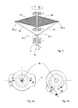
- FIG. 1 shows a kinematic scheme of the spatial coupling transmission according to the invention.
- the transmission can be broken down into two four-membered transmissions, namely a first four-member with a frame 1, a drive member 2, a first coupling 3a and a first output member 4a and a second four-member with a frame 1, a drive member 2, a second coupling 3b and a second output member 4b.
- the coupling 3a, 4a are connected via the joints g 2,3a and g 2,3b to the drive member 2 and the joints g 3a, 4a and g 3b, 4b with the output members 4a, 4b.
- a translational movement of the drive member 2 along the axis Ax according to arrow T is converted into a swinging movement of the output members 4a, 4b about the axis Ax according to arrow R, wherein the directions of rotation of the output members 4a, 4b are opposite to each other.
- the coupling 3a, 3b perform in the adjustment of each a spatial movement.
- FIG. 2a shows a front view of an embodiment of the vibration exciter according to the invention in a position in which the partial imbalances generated by the imbalance weights 20, 30 cancel each other, so that the total imbalance is minimal, that is substantially zero.
- the center of gravity S which is formed on the one hand from the partial center of gravity S1 of the first imbalance weight 20 and on the other from the partial center of gravity S2 of the second imbalance weight 30, lies in this position on the horizontal H, so that there is no radial distance to the axis of rotation Ax. Thus, no appreciable imbalance occurs.
- FIG. 2b shows the front view of the vibration exciter Fig. 2a in a position in which the oscillation amplitude or the total imbalance is maximum.
- the imbalance weights 20, 30 and thus also their centers of gravity S1, S2 are rotated along the arrow directions shown to each other, so that the center of gravity S now has a significant distance from the horizontal H or the axis of rotation Ax.
- the distance of the center of gravity S from the axis of rotation can be between the in Fig. 2a shown, minimum value 0 and the in Fig. 2b shown, maximum value can be adjusted continuously.
- FIG. 3 shows a perspective view of the vibrator 10 according to the invention for a better overview, in this case the housing is not shown.
- the vibration exciter essentially comprises the gear 11, which in turn comprises an adjusting slide 12, the two coupling links 13, 14, the imbalance weights 20, 30 and the four pivot joints 15.
- the exciter housing not shown here corresponds to the in Fig. 1 shown frame 1.
- the adjusting slide 12 corresponds to the drive member 2 from Fig. 1
- the coupling links 13, 14 represent the coupling 3a, 3b Fig. 1
- the imbalance weights 20, 30 correspond to the output members 4a, 4b Fig.
- the four hinge joints 15 make the joints g 2,3a , g 2,3b , g 3a, 4ab g 3b, 4b Fig. 1
- the shaft 18 of the vibration generator 10 is firstly composed of a first hollow-bored partial shaft 21, which carries the first imbalance weight 20, and on the other hand from a second hollow-drilled partial shaft 31, which carries the second imbalance weight 30. In the position shown, no unbalance is generated ( Fig. 2a ).
- FIG. 4 shows a perspective view of the vibration exciter 10 Fig. 3 , but in a position where the generated imbalance is maximum ( Fig. 2b ).
- the adjusting slide 12 is pushed in the direction of the imbalance weights 20, 30.
- the articulated with the adjusting slide, rigid coupling members 13, 14 each perform a spatial movement, whereby the articulated weights also associated with them unbalanced weights 20, 30 together with the partial shafts 21, 31 perform a rotational movement about the axis of rotation Ax.
- the vibration exciter caused by the gear 11 rotational movements of the imbalance weights 20, 30 of the excitation drive or vibration drive (not shown) caused rotational movement of the imbalance weights 20, 30 are superimposed.
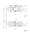
- FIGS. 5a, 5b the plan views of the vibrator 10 are shown before and after the adjustment.
- one end of the adjusting slide 12 is at position X1.
- FIG. 5b shown is the addressed end of the adjusting slide 12 via a hydraulic cylinder or a linear motor (both not shown) for the purpose of adjusting the unbalance by the amount X placed in the position X2.
- the imbalance weights 20, 30 are rotated about the axis of rotation Ax to each other, so that in the plan view, a distance Y2, which is smaller than the distance Y1 from Fig. 5a . is recognizable. Any position of the adjusting slide 12 between X1 and X2 is infinitely adjustable.
- FIG. 6 shows a part of the transmission 11 from Fig. 3 ,
- the adjusting slide 12 essentially comprises a cylindrical part, which is guided in the bore of the partial shaft 31.
- a shaft shoulder can be seen, which serves to receive a Wälziagerung (not shown).
- the rigid coupling members 13, 14, which in each case again by means of hinge joints 15 with the imbalance weights 20, 30 (not shown here) are connected.
- FIGS. 7 and 8 are the imbalance weights 20, 30 off Fig. 3 shown in detail.
- the partial waves 21, 31 produced integrally with the imbalance weights 20, 30 are also clearly visible.
- the imbalance weights 20, 30 are identical in construction.
- the one end (with the larger bore) of the second imbalance weight 30 on the outer circumferential surface of the partial shaft 21 of the first imbalance weight 20 can rotate rotationally.
- the one end of the first imbalance weight together with the part shaft 31 of the second imbalance weight also forms a rotary sliding surface.
- the axial extent of the imbalance weights 20, 30 substantially corresponds to the axial extent of the shaft 18 with the partial shafts 21, 31.
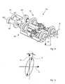
- FIG. 9 is a directional vibrator 50 with two vibrators according to the invention including excitation housing 19 and cover 17 is shown.
- the directional vibrator 50 is off Fig. 9 shown, but without cover 17 and exciter housing 19.
- the directional vibrator 50 includes two juxtaposed vibration exciters 10, 40, which means (not shown) for synchronously opposing rotation of the unbalanced shafts have.
- a main adjusting cylinder 41 with an adjusting piston 42. That with the adjusting piston 42 connected connecting member 44 provides for a synchronous adjustment of the adjusting slide of the vibration exciter 10, 40.
- the auxiliary cylinder 43 is provided to make a phase adjustment of the imbalance shaft of the vibration exciter 40 relative to the imbalance shaft of the vibration exciter 10.
- the unbalance shafts of the vibration exciter 10, 40 in the same phase with maximum imbalance.
- the excitation force generated by the directional oscillator 50 is directed vertically upwards or downwards.
- FIG. 11 shows the directional oscillator 50 Fig. 10 , but with a phase shift.
- the phase of the shaft of the first vibration exciter 10 relative to the shaft of the second vibration exciter 40 is displaced by the fact that the imbalance of the first vibration exciter 10 due to an adjusting movement has an eccentricity e1, which - as also schematically in Fig. 11
- the eccentricity e2 of the imbalance of the second vibration exciter 40 is Unbalance of the first vibration exciter 10 is smaller than the imbalance of the second vibration exciter 40.
- a directional vibration is generated whose axis A is not vertical, ie perpendicular to the horizontal H, but by a certain angle, For example, 15 °, is inclined relative to the vertical axis V, as well as in FIG. 12 good to see.
- This may expediently be used for setting an independent forward or backward movement of a vibration plate, which comprises a directional vibrator 50 according to the invention.
Landscapes
- Engineering & Computer Science (AREA)
- Mechanical Engineering (AREA)
- Apparatuses For Generation Of Mechanical Vibrations (AREA)
Abstract
Description
- Die Erfindung betrifft gemäß dem Oberbegriff des Anspruchs 1 einen Schwingungserreger mit einer Welle und mit mindestens zwei auf der Welle angeordneten Unwuchtgewichten, bei dem der radiale Abstand des gemeinsamen Schwerpunktes der Unwuchtgewichte von der Rotationsachse der Welle mittels eines Getriebes stufenlos verstellbar ist.
- Bei einem aus der
DE 24 09 41 7 A1 bekannten Schwingungserreger mit zwei Unwuchten wird zwecks Verstellung der Phasenlage der Unwuchten ein Stift eingesetzt, welcher in eine schraubenförmig verlaufende Nut einer Nabe eingreift. Eine translatorische Bewegung des Stiftes ruft eine rotatorische Bewegung der Nabe hervor, so dass ein gegenseitiges Verdrehen der Unwuchten ermöglicht wird. Hierbei ist es nachteilig, dass hohe Verstellkräfte aufgebracht werden müssen. Des weiteren besteht der Nachteil darin, dass eine aufwendige Kopplung zwischen den Unwuchten vorgesehen werden muss. Dies führt nicht nur zu höheren Kosten, sondern auch zu größerem Bauraumbedarf. - Aus der
DD 265 113 A1 - Der Erfindung liegt daher die Aufgabe zugrunde, einen Schwingungserreger der eingangs genannten Art anzugeben, der die Nachteile der bekannten Schwingungserreger des Standes der Technik überwindet.
- Diese Aufgabe wird gelöst durch den Gegenstand des unabhängigen Anspruchs 1. Die abhängigen Ansprüche sind auf vorteilhafte Ausführungsformen der Erfindung gerichtet.
- Der erfindungsgemäße Schwingungserreger weist ein Getriebe auf, welches ein räumliches Koppelgetriebe, beispielsweise ein räumliches Schubschwingengetriebe, ist.
- "Koppetgetriebe", wie beispielsweise Schubschwingen, Schubkurbeln, Kurbelschwingen etc., gehören zur Gruppe der ungleichmäßig übersetzenden Getriebe und kommen dann zum Einsatz, wenn eine Umwandlung einer Drehbewegung in eine oszillierende (geradlinige oder schwingende) Bewegung und umgekehrt erforderlich ist. Koppelgetriebe weisen mindestens vier Getriebeglieder auf, die durch Gleitgelenke, d. h. Gelenke wie beispielsweise Schub- und Drehgelenke, deren Elemente aufeinander gleiten bzw. sich in Flächen berühren, verbunden sind. Alle Koppelgetriebe weisen mindestens eine feste Koppel auf, welche ein nicht im Gestell gelagertes oder geführtes Übertragungsglied darstellt. Je nach Anwendungsfall können die Koppel bzw. Koppelglieder als Pleuel, Treibstangen etc. ausgeführt sein.
- Im Vergleich zu Kurvengetrieben, die eine weit verbreitete Getriebeart bilden, erlauben Koppelgetriebe eine einfachere und günstigere Fertigung der Getriebeglieder. Zudem sind Koppelgetriebe dank höherer Belastbarkeit der Gleitgelenke als robuster anzusehen.
- Weit verbreitet sind "ebene Koppelgetriebe". Ebene Koppelgetriebe zeichnen sich dadurch aus, dass die Gliedpunkte aller Glieder eine ebene Bewegung ausführen, d. h. nur Bahnen in einer Ebene oder zueinander parallelen Ebenen. Davon zu unterscheiden sind "sphärische Koppelgetriebe", deren sämtliche Gliedpunkte nur auf Bahnen auf zueinander konzentrischen Kugelflächen durchlaufen können.
- Erfindungsgemäß ist vorgesehen, dass das Getriebe zur Verstellung des Schwerpunktes der Unwuchtgewichte ein räumliches Koppelgetriebe ist. Im Unterschied zu ebenen oder sphärischen können bei räumlichen Koppelgetrieben Gliedpunkte mindestens eines Gliedes gegenüber mindestens einem anderen Glied eine räumliche Bewegung ausführen. Unter einer räumlichen Bewegung wird eine Bewegung verstanden, bei welcher wenigstens ein Punkt eines Körpers eine räumliche Bahn durchläuft, die nicht mehr in einer Ebene liegt. Bei räumlichen Koppelgetrieben gelten im Vergleich zu ebenen oder sphärischen Koppelgetrieben komplett andere Analyse- und Syntheseverfahren.
- Mit Hilfe des erfindungsgemäßen Schwingungserregers wird in einfacher und kostengünstiger Weise eine stufenlose Verstellung der Amplitude der Schwingung bzw. der Erregerkraft während des Betriebes ermöglicht. Dank der erfindungsgemäßen Getriebekinematik sind die benötigten Verstellkräfte sehr gering. Zudem kann der erfindungsgemäße Schwingungserreger platzsparend gebaut werden.
- In einer vorteilhaften Ausführungsform der Erfindung umfasst das Getriebe einen Verstellschieber und Koppelglieder, wobei jedes Koppelglied mittels Drehgelenkverbindungen mit dem Verstellschieber und einem der Unwuchtgewichte verbunden ist.
- Gemäß dieser Ausführungsform handelt es sich beim erfindungsgemäßen Getriebe um ein räumliches Koppelgetriebe mit einem Gestell, einem als Verstellschieber ausgeführtes Antriebsglied, zwei Koppelgliedern und zwei Abtriebsgliedern, welche vorzugsweise mit den Unwuchtgewichten verbunden sind bzw. die Unwuchtgewichte selbst sind. Es handelt sich also um ein Parallelgetriebe mit zwei viergliedrigen Koppelgetrieben.
- In einer weiteren bevorzugten Ausführungsform der Erfindung weisen die Drehgelenkverbindungen je einen Gelenkfreiheitsgrad von f=2 auf.
- Unter Gelenkfreiheitsgrad wird der Freiheitsgrad verstanden, den ein Gelenk einem Glied gegenüber dem mit ihm durch das Gelenk verbundenen anderen Glied zumisst. Da es sich hierbei um Drehgelenkverbindungen handelt, erlaubt jede Drehgelenkverbindung zwei Drehbewegungen um zwei unterschiedliche Rotationsachsen. Anstelle einer Drehgelenkverbindung mit einem Gelenkfreiheitsgrad von f=2 kann auch eine Drehgelenk mit einem höheren Gelenkfreiheitsgrad von f=3 verwendet werden, was beispielsweise bei einem Kugelgelenk der Fall ist.
- Gemäß einer vorteilhaften Ausführungsform der Erfindung umfassen die Drehgelenkverbindungen je einen drehbar gelagerten Gabelkopf.
- Mit dieser Ausführungsform wird in einfacher und robuster Weise eine Drehgelenkverbindung mit einem Gelenkfreiheitsgrad von f=2 geschaffen. Die erste Drehachse befindet sich wie bei üblichen Gabelgelenken in der Bolzenachse, die durch die Wangen des Gabelkopfes verläuft. Durch die rotierbare Lagerung des Gabelkopfes wird eine zweite Drehachse gebildet, die als eine Hochachse des Gabelkopfes senkrecht zur ersten Drehachse und mittig zwischen den Wangen des Gabelkopfes verläuft.
- Gemäß einer weiteren vorteilhaften Ausführungsform der Erfindung weist die Welle koaxiale Teilwellen auf, welche jeweils ein mit ihr dreh- und achsfest verbundenes Unwuchtgewicht aufweisen, wobei die Teilwellen über rotatorische Gleitflächen einander benachbart angeordnet sind.
- Gemäß dieser Ausführungsform kann das Gesamtgewicht des Schwingungserregers reduziert werden, da die Welle nicht durchgehend ausgeführt sein muss. Zudem kann die Herstellung des Erregers durch die Kopplung der Unwuchtgewichte an die jeweiligen Teilwellen in einfacher Weise beispielsweise mit Hilfe eines Gussverfahren vereinfacht werden. Die beiden Unwuchtgewichte, die einander über rotatorische Gleitflächen benachbart angeordnet sind, sind derart aneinander gekoppelt und in einem gemeinsamen Gestell gelagert, dass ein einziger Verstellantrieb ausreicht, um die beiden Unwuchtgewichte relativ zueinander zu verdrehen. Die beiden Unwuchtgewichte werden bezüglich des Mittelpunktes der Welle spiegelverkehrt angeordnet. Allerdings sind sie gleich in ihrer Form und Größe, so dass eine einfache Fertigung ermöglicht wird. Vorzugsweise erstrecken sich die Unwuchtgewichte axial im Wesentlichen über die gesamte Länge der Welle. Somit entsteht ein äußerst kompakter Schwingungserreger.
- Die Erfindung betrifft ferner einen Richtschwinger zur Erzeugung einer gerichteten Schwingung mit mindestens zwei erfindungsgemäßen Schwingungserregern, wobei die Phase zwischen den Wellen der Schwingungserreger stufenlos verschiebbar ist.
- Durch eine Kopplung von mindestens zwei erfindungsgemäßen Schwingungserregern, wobei die Kopplung eine zueinander gegensinnige und synchrone Rotation der Unwuchtwellen ermöglicht, wird aus zwei einzelnen umlaufenden Kreiserregern ein Richtschwinger geschaffen, welcher infolge der Überlagerung von Einzelschwingungen eine gerichtete Schwingung auf einer bestimmten Achse erzeugen kann. In Vorrichtungen zur Bodenverdichtung beispielsweise werden vorwiegend vertikal gerichtete Schwingungen erzeugt. Vorzugsweise ist beim erfindungsgemäßen Richtschwinger neben der Amplitude der Schwingungen auch die Phase zwischen den einzelnen Schwingungserregern stufenlos verschiebbar. Unter der Phase werden in diesem Zusammenhang zum einen die Lage der Erreger- bzw. Unwuchtwelle bezüglich einer frei zu bestimmenden Bezugsposition und zum anderen aber auch das Größenverhältnis der Unwuchten zueinander verstanden. Laufen die beiden Unwuchtwellen gleichphasig, d. h. sind die um die jeweilige Drehachse rotierenden Schwerpunktsvektoren der Unwuchtwellen in wenigstens zwei Stellungen parallel zueinander angeordnet und sind die Unwuchten der beiden Unwuchtwellen gleich groß, dann werden nur Kräfte in vertikaler Richtung erzeugt. Haben die beiden Unwuchtwellen allerdings eine unterschiedliche Phase zueinander, d. h. weisen die Schwerpunktsvektoren der Unwuchtwellen keine Stellung auf, in der sie parallel zueinander angeordnet sind oder sind die Unwuchten der Unwuchtwellen unterschiedlich groß, so neigt sich die Achse der gerichteten Schwingung um einen gewissen Winkel gegenüber der Vertikalen. Dies kann beispielsweise vorteilhaft sein, um zusätzlich zur Verdichtung des Bodens einen Vortrieb des Richtschwingers zu erzeugen und anzupassen.
- Des weiteren betrifft die Erfindung eine Vibrationsplatte oder -walze mit einem Richtschwinger mit zwei erfindungsgemäßen Schwingungserregern. Die Vibrationsplatte oder -walze kann somit einfach und kostengünstig hergestellt und mit nur geringen Verstellkräften während des Betriebes verstellt werden. Nicht nur die Amplitude der gerichteten Schwingung, sondern auch die Neigung der Schwingungsachse gegenüber der Vertikalen können stufenlos verstellt werden, so dass je nach Anwendungsfall die Größe der Unwucht sowie die Geschwindigkeit und die Fahrtrichtung der Vibrationsplatte bzw. -walze angepasst werden können.
- Nachfolgend wird die Erfindung anhand von Ausführungsbeispielen weiter erläutert. Es zeigen schematisch:
- Figur 1
- Ein kinematisches Schema des erfindungsgemäßen räumlichen Koppelgetriebes;
- Figur 2a
- eine Vorderansicht des Schwingungserregers bei minimaler Unwucht;
- Figur 2b
- eine Vorderansicht des Schwingungserregers bei maximaler Unwucht;
- Figur 3
- eine perspektivische Ansicht des Schwingungserregers bei minimaler Unwucht;
- Figur 4
- eine perspektivische Ansicht des Schwingungserregers bei maximaler Unwucht;
- Figur 5a
- eine Draufsicht des Schwingungserregers bei minimaler Unwucht;
- Figur 5b
- eine Draufsicht des Schwingungserregers bei maximaler Unwucht;
- Figur 6
- eine perspektivische Ansicht des Verstellschiebers mit den Koppelgliedern und Drehgelenkverbindungen aus
Fig. 3 ; - Figur 7
- eine perspektivische Ansicht des ersten Unwuchtgewichtes aus
Fig. 3 ; - Figur 8
- eine perspektivische Ansicht des zweiten Unwuchtgewichtes aus
Fig. 3 ; - Figur 9
- eine perspektivische Ansicht des Richtschwingers;
- Figur 10
- eine perspektivische Ansicht des Richtschwingers aus
Fig. 9 ohne Erregergehäuse und Deckel bei maximaler Unwucht; - Figur 11
- eine perspektivische Ansicht des Richtschwingers aus
Fig. 10 mit Phasenverschiebung; - Figur 12
- Amplitudenverlauf der gerichteten Schwingung bei Phasenverschiebung gemäß
Fig. 11 . -
Figur 1 zeigt ein kinematisches Schema des erfindungsgemäßen räumlichen Koppelgetriebes. Das Getriebe lässt sich in zwei viergliedrige Getriebe zerlegen, nämlich in ein erstes Vierglied mit einem Gestell 1, einem Antriebsglied 2, einer ersten Koppel 3a und einem ersten Abtriebsglied 4a sowie ein zweites Vierglied mit einem Gestell 1, einem Antriebsglied 2, einer zweiten Koppel 3b und einem zweiten Abtriebsglied 4b. Die Koppel 3a, 4a sind über die Gelenke g2,3a und g2,3b mit dem Antriebsglied 2 und über die Gelenke g3a,4a und g3b,4b mit den Abtriebsgliedern 4a, 4b verbunden. Eine translatorische Bewegung des Antriebsgliedes 2 entlang der Achse Ax gemäß Pfeil T wird in eine schwingende Bewegung der Abtriebsglieder 4a, 4b um die Achse Ax gemäß Pfeil R umgeformt, wobei die Drehrichtungen der Abtriebsglieder 4a, 4b einander entgegengesetzt sind. Die Koppel 3a, 3b führen bei der Verstellung jeweils eine räumliche Bewegung aus. -
Figur 2a zeigt eine Vorderansicht eines Ausführungsbeispiels des erfindungsgemäßen Schwingungserregers in einer Stellung, in der die durch die Unwuchtgewichte 20, 30 erzeugten Teilunwuchten sich gegenseitig aufheben, so dass die Gesamtunwucht minimal ist, d. h. im Wesentlichen null ist. Der Schwerpunkt S, welcher zum einen aus dem Teilschwerpunkt S1 des ersten Unwuchtgewichtes 20 und zum anderen aus dem Teilschwerpunkt S2 des zweiten Unwuchtgewichtes 30 gebildet wird, liegt in dieser Stellung auf der Horizontalen H, so dass kein radialer Abstand zur Rotationsachse Ax vorliegt. Damit tritt auch keine nennenswerte Unwucht auf. -
Figur 2b zeigt die Vorderansicht des Schwingungserregers ausFig. 2a in einer Stellung, in der die Schwingungsamplitude bzw. die Gesamtunwucht maximal ist. Durch das Getriebe zur Verstellung werden die Unwuchtgewichte 20, 30 und damit auch deren Schwerpunkte S1, S2 entlang der gezeigten Pfeilrichtungen zueinander verdreht, so dass der Schwerpunkt S nun einen deutlichen Abstand zur Horizontalen H bzw. der Rotationsachse Ax aufweist. Je größer der Abstand des Schwerpunktes S von der Rotationsachse Ax ist, desto größer ist die erzeugte Unwucht. Der Abstand des Schwerpunktes S von der Rotationsachse kann zwischen dem inFig. 2a gezeigten, minimalen Wert 0 und dem inFig. 2b gezeigten, maximalen Wert stufenlos eingestellt werden. -
Figur 3 zeigt eine perspektivische Ansicht des erfindungsgemäßen Schwingungserregers 10. Zur besseren Übersicht ist hierbei das Gehäuse nicht gezeigt. Der Schwingungserreger umfasst im Wesentlichen das Getriebe 11, welches seinerseits einen Verstellschieber 12, die beiden Koppelglieder 13, 14 die Unwuchtgewichte 20, 30 sowie die vier Drehgelenkverbindungen 15 umfasst. Das hier nicht gezeigte Erregergehäuse entspricht dem inFig. 1 gezeigten Gestell 1. Der Verstellschieber 12 entspricht dem Antriebsglied 2 ausFig. 1 . Die Koppelglieder 13, 14 repräsentieren die Koppel 3a, 3b ausFig. 1 . Die Unwuchtgewichte 20, 30 entsprechen den Abtriebsgliedern 4a, 4b ausFig. 1 . Die vier Drehgelenkverbindungen 15 stellen die Gelenke g2,3a, g2,3b, g3a,4ab g3b,4b ausFig. 1 dar. Die Welle 18 des Schwingungserregers 10 wird zum einen aus einer ersten hohlgebohrten Teilwelle 21, welche das erste Unwuchtgewicht 20 trägt, und zum anderen aus einer zweiten hohlgebohrten Teilwelle 31, welche das zweite Unwuchtgewicht 30 trägt, zusammengesetzt. In der gezeigten Stellung wird keine Unwucht erzeugt (Fig. 2a ). -
Figur 4 zeigt eine perspektivische Ansicht des Schwingungserregers 10 ausFig. 3 , allerdings in einer Stellung, bei der die erzeugte Unwucht maximal ist (Fig. 2b ). Dazu wird der Verstellschieber 12 in Richtung der Unwuchtgewichte 20, 30 hineingeschoben. Die mit dem Verstellschieber gelenkig verbundenen, starren Koppelglieder 13, 14 führen jeweils eine räumliche Bewegung aus, wodurch die mit ihnen ebenfalls gelenkig verbundenen Unwuchtgewichte 20, 30 samt den Teilwellen 21, 31 eine Drehbewegung um die Rotationsachse Ax ausführen. Während des Betriebes des Schwingungserregers sind die durch das Getriebe 11 hervorgerufenen Drehbewegungen der Unwuchtgewichte 20, 30 der durch den Erregerantrieb bzw. Vibrationsantrieb (nicht gezeigt) hervorgerufenen Drehbewegung der Unwuchtgewichte 20, 30 überlagert. - In
Figuren 5a, 5b sind die Draufsichten des Schwingungserregers 10 vor und nach der Verstellung gezeigt. In der Ausgangsstellung, wenn keine Unwucht erzeugt werden soll (Fig. 2a ), befindet sich das eine Ende des Verstelischiebers 12 auf der Position X1. Dabei liegen die Lagerstellen L1, L2, an denen die Gabelköpfe 15 der Drehgelenkverbindungen 15 drehbar gelagert sind, um einen Abstand Y1 voneinander entfernt. - Wie in
Figur 5b gezeigt wird das angesprochene Ende des Verstellschiebers 12 über einen Hydraulikzylinder oder einen Linearmotor (beide nicht gezeigt) zwecks Verstellung der Unwucht um den Betrag X in die Position X2 gebracht. Dies entspricht der Stellung für die maximale Unwucht (Fig. 2b ). Die Unwuchtgewichte 20, 30 werden um die Rotationsachse Ax zueinander verdreht, so dass in der Draufsicht ein Abstand Y2, welcher kleiner ist als der Abstand Y1 ausFig. 5a , erkennbar ist. Jede beliebige Position des Verstellschiebers 12 zwischen X1 und X2 ist stufenlos einstellbar. -
Figur 6 zeigt ein Teil des Getriebes 11 ausFig. 3 . Der Verstellschieber 12 umfasst im Wesentlichen einen zylindrischen Teil, welcher in der Bohrung der Teilwelle 31 geführt ist. An dem linken Ende des Verstellschiebers 12 ist ein Wellenabsatz erkennbar, welcher zur Aufnahme einer Wälziagerung (nicht gezeigt) dient. Am gegenüberliegenden Ende des Verstellschiebers 12 sind zwei Gabelköpfe 16 um jeweils eine Hochachse drehbar gelagert und bilden jeweils eine Drehgelenkverbindung 15 mit einem Gelenkfreiheitsgrad von f=2. Damit verbunden sind die starren Koppelglieder 13, 14, welche jeweils wieder mittels Drehgelenkverbindungen 15 mit den Unwuchtgewichten 20, 30 (hier nicht gezeigt) verbunden sind. Anstelle der gezeigten Drehgelenkverbindungen 15 mit drehbar gelagerten Gabelköpfen 16 können die Koppelglieder 13, 14 auch über Kugelgelenke (f=3) drehbar am Verstellschieber 12 bzw. an den Unwuchtgewichten 20, 30 gekoppelt sein. Alternativ ist es auch möglich, Gelenklager zur drehbaren Verbindung der Koppelglieder 13, 14 am Verstellschieber 12 bzw. an den Unwuchtgewichten 20, 30 vorzusehen. - In
Figuren 7 und 8 sind die Unwuchtgewichte 20, 30 ausFig. 3 im Detail gezeigt. Gut sichtbar sind die mit den Unwuchtgewichten 20, 30 integral hergestellten Teilwellen 21, 31. Ebenfalls gut sichtbar ist, dass die Unwuchtgewichte 20, 30 baugleich sind. Im zusammengebauten Zustand kann das eine Ende (mit der größeren Bohrung) des zweiten Unwuchtgewichtes 30 auf der äußeren Mantelfläche der Teilwelle 21 des ersten Unwuchtgewichtes 20 rotatorisch gleiten. Dementsprechend bildet das eine Ende des ersten Unwuchtgewichtes zusammen mit der Teilwelle 31 des zweiten Unwuchtgewichtes auch eine rotatorische Gleitfläche. Beim Verstellen des Schwerpunktsabstands gleiten die genanten Gleitpartner relativ zueinander. Gut erkennbar ist ferner, dass die axiale Erstreckung der Unwuchtgewichte 20, 30 im Wesentlichen der axialen Erstreckung der Welle 18 mit den Teilwellen 21, 31 entspricht. - In
Figur 9 ist ein Richtschwinger 50 mit zwei Schwingungserregern gemäß Erfindung samt Erregergehäuse 19 und Deckel 17 gezeigt. - In
Figur 10 ist der Richtschwinger 50 ausFig. 9 gezeigt, allerdings ohne Deckel 17 und Erregergehäuse 19. Der Richtschwinger 50 umfasst zwei nebeneinander angeordnete Schwingungserreger 10, 40, welche Mittel (nicht gezeigt) zur synchron gegensinnigen Rotation der Unwuchtwellen aufweisen. Anstelle der Verstellung mittels separater Verstellzylinder ist es zweckmäßig einen Hauptverstellzylinder 41 mit einem Verstellkolben 42 vorzusehen. Das mit dem Verstellkolben 42 verbundene Verbindungselement 44 sorgt für eine synchrone Verstellung der Verstellschieber der Schwingungserreger 10, 40. Der Hilfszylinder 43 ist dazu vorgesehen, um eine Phasenverstellung der Unwuchtwelle des Schwingungserregers 40 gegenüber der Unwuchtwelle des Schwingungserregers 10 vornehmen zu können. In der inFig. 10 gezeigten Stellung laufen die Unwuchtwellen der Schwingungserreger 10, 40 in gleicher Phase mit maximaler Unwucht. Damit ist die durch den Richtschwinger 50 erzeugte Erregerkraft vertikal nach oben bzw. unten gerichtet. -
Figur 11 zeigt den Richtschwinger 50 ausFig. 10 , allerdings mit einer Phasenverschiebung. Hierbei ist die Phase der Welle des ersten Schwingungserregers 10 gegenüber der Welle des zweiten Schwingungserregers 40 dadurch verschoben, dass die Unwucht des ersten Schwingungserregers 10 aufgrund einer Verstellbewegung eine Exzentrizität e1 aufweist, welche - wie auch schematisch inFig. 11 dargestellt - einen geringeren Wert aufweist als die Exzentrizität e2 der Unwucht des zweiten Schwingungserregers 40. Da die Unwucht U gemäß der Formel U = m * e aus dem Produkt der Masse m und der Exzentrizität e (Schwerpunktsabstand von der Rotationsachse) berechnet wird, ist die Unwucht des ersten Schwingungserregers 10 kleiner als die Unwucht des zweiten Schwingungserregers 40. Infolge der synchron gegensinnigen Rotation der Wellen der Schwingungserreger 10, 40 wird eine gerichtete Schwingung erzeugt, deren Achse A nicht vertikal, d. h. senkrecht zur Horizontalen H, sondern um einen gewissen Winkel, beispielsweise 15°, gegenüber der vertikalen Achse V geneigt ist, wie auch inFigur 12 gut erkennbar. Dies kann zweckmäßiger Weise zur Einstellung einer eigenständigen Vorwärts- oder Rückwärtsbewegung einer Vibrationsplatte, welche einen erfindungsgemäßen Richtschwinger 50 umfasst, genutzt werden.
Claims (7)
- Schwingungserreger (10) mit einer Welle (18) und mit mindestens zwei auf der Welle angeordneten Unwuchtgewichten (20, 30), wobei der radiale Abstand des gemeinsamen Schwerpunktes der Unwuchtgewichte (20, 30) von der Rotationsachse (Ax) der Welle (18) mittels eines Getriebes (11) stufenlos verstellbar ist,
dadurch gekennzeichnet,
dass das Getriebe (11) ein räumliches Koppelgetriebe, beispielsweise ein räumliches Schubschwingengetriebe, ist. - Schwingungserreger (10) nach Anspruch 1,
dadurch gekennzeichnet,
dass das Getriebe (11) einen Verstellschieber (12) und Koppelglieder (13, 14) umfasst, wobei jedes Koppelglied (13, 14) mittels Drehgelenkverbindungen (15) mit dem Verstellschieber (12) und einem der Unwuchtgewichte (20, 30) verbunden ist. - Schwingungserreger (10) nach Anspruch 2,
dadurch gekennzeichnet,
dass die Drehgelenkverbindungen (15) je einen Gelenkfreiheitsgrad von f=2 aufweisen. - Schwingungserreger (10) nach Anspruch 2 oder 3,
dadurch gekennzeichnet,
dass die Drehgelenkverbindungen (15) je einen drehbar gelagerten Gabelkopf (16) umfassen. - Schwingungserreger (10) nach einem der vorhergehenden Ansprüche,
dadurch gekennzeichnet,
dass die Welle (18) koaxiale Teilwellen (21, 31) aufweist, welche jeweils ein mit ihr dreh- und achsfest verbundenes Unwuchtgewicht (20, 30) aufweisen, wobei die Teilwellen (21, 31) über rotatorische Gleitflächen einander benachbart angeordnet sind. - Richtschwinger (50) zur Erzeugung einer gerichteten Schwingung mit mindestens zwei Schwingungserregern (10, 40) nach einem der vorhergehenden Ansprüche, wobei die Phase zwischen den Wellen der Schwingungserreger (10, 40) stufenlos verschiebbar ist.
- Vibrationsplatte oder -walze mit einem Richtschwinger (50) nach Anspruch 6.
Applications Claiming Priority (1)
| Application Number | Priority Date | Filing Date | Title |
|---|---|---|---|
| DE102010010037.4A DE102010010037B4 (de) | 2010-03-03 | 2010-03-03 | Stufenlos verstellbarer Schwingungserreger |
Publications (3)
| Publication Number | Publication Date |
|---|---|
| EP2363212A2 true EP2363212A2 (de) | 2011-09-07 |
| EP2363212A3 EP2363212A3 (de) | 2016-11-09 |
| EP2363212B1 EP2363212B1 (de) | 2019-10-02 |
Family
ID=44148895
Family Applications (1)
| Application Number | Title | Priority Date | Filing Date |
|---|---|---|---|
| EP11000185.6A Active EP2363212B1 (de) | 2010-03-03 | 2011-01-12 | Stufenlos verstellbarer Schwingungserreger |
Country Status (4)
| Country | Link |
|---|---|
| US (1) | US8881612B2 (de) |
| EP (1) | EP2363212B1 (de) |
| CN (1) | CN102189075B (de) |
| DE (1) | DE102010010037B4 (de) |
Families Citing this family (6)
| Publication number | Priority date | Publication date | Assignee | Title |
|---|---|---|---|---|
| DE102011112316B4 (de) * | 2011-09-02 | 2020-06-10 | Bomag Gmbh | Schwingungserreger zur Erzeugung einer gerichteten Erregerschwingung |
| WO2013186739A2 (en) * | 2012-06-13 | 2013-12-19 | Ozkan Aydin | A location changer with variable momentum |
| DE102012025376A1 (de) | 2012-12-27 | 2014-07-03 | Wacker Neuson Produktion GmbH & Co. KG | Schwingungserreger für lenkbare bodenverdichtungsvorrichtungen |
| US9039531B2 (en) * | 2013-02-05 | 2015-05-26 | Microsoft Technology Licensing, Llc | Rumble motor movement detection |
| US9941779B2 (en) * | 2015-05-08 | 2018-04-10 | Dynamic Structures And Materials, Llc | Linear or rotary actuator using electromagnetic driven hammer as prime mover |
| DE102023200675B4 (de) | 2023-01-27 | 2025-10-30 | Bomag Gmbh | Schwingungserreger für ein bodenverdichtungsgerät, verfahren zum einstellen einer schwingungsamplitude eines schwingungserregers für ein bodenverdichtungsgerät sowie bodenverdichtungsgerät mit einem schwingungserreger |
Citations (2)
| Publication number | Priority date | Publication date | Assignee | Title |
|---|---|---|---|---|
| DE2409417A1 (de) | 1974-02-27 | 1975-09-04 | Wacker Werke Kg | Schwingungserreger mit zwei relativ zueinander in der phasenlage kontinuierlich verstellbaren unwuchten |
| DD265113A1 (de) | 1987-09-15 | 1989-02-22 | Erfurt Wohnungsbau | Gegenlaufvibrator mit waehrend des betriebes vornehmbarer kontinuierlicher erregerkrafteinstellung |
Family Cites Families (25)
| Publication number | Priority date | Publication date | Assignee | Title |
|---|---|---|---|---|
| FR1445736A (fr) * | 1965-06-04 | 1966-07-15 | Procedes Tech Const | Appareil d'enfoncement ou d'arrachage par vibration |
| DE1758226A1 (de) * | 1968-04-26 | 1971-01-14 | Losenhausen Maschb Ag | Unwuchtruettler |
| US3919575A (en) * | 1973-10-03 | 1975-11-11 | Bosch Gmbh Robert | Vibrator generator |
| US4005687A (en) * | 1974-02-01 | 1977-02-01 | Johan Jonathan | Concealed regenerative combustion engine |
| US4096762A (en) * | 1976-07-30 | 1978-06-27 | Bodine Albert G | Torsional sonic oscillator employing universal joints and tandem arranged oscillator rotors |
| DE2706053A1 (de) * | 1977-02-12 | 1978-08-17 | Bosch Gmbh Robert | Elektromotorisch angetriebener unwuchtvibrator |
| CA1103960A (en) * | 1977-11-23 | 1981-06-30 | William J. Glazier | Variable throw eccentric |
| US4266434A (en) * | 1978-11-30 | 1981-05-12 | Burns David L | Rotating oscillatory motion power take-off |
| CN85204426U (zh) * | 1985-10-16 | 1986-09-10 | 城乡建设环境保护部长沙建筑机械研究所 | 振动器偏心力矩调整装置 |
| US4928554A (en) * | 1988-12-29 | 1990-05-29 | Dryga Alexandr I | Unbalance vibrator |
| US5177386A (en) * | 1990-08-30 | 1993-01-05 | Kencho Kobe Co., Ltd. | Vibration generator adjustable during operation |
| DE29805619U1 (de) * | 1998-03-27 | 1999-07-29 | Passavant-Werke Ag, 65326 Aarbergen | Vibrations-Verdichtungssystem zum Verdichten von Formmassen in Formkästen |
| US6139218A (en) * | 1998-07-31 | 2000-10-31 | Cochran; Gary | Vibrating mechanism |
| US6224293B1 (en) * | 1999-04-19 | 2001-05-01 | Compaction America, Inc. | Variable amplitude vibration generator for compaction machine |
| US6516679B2 (en) * | 2001-01-29 | 2003-02-11 | Ingersoll-Rand Company | Eccentric assembly with eccentric weights that have a speed dependent phased relationship |
| US20020104393A1 (en) * | 2001-02-07 | 2002-08-08 | Van Es J. R. | Variable moment vibrator |
| US6637280B2 (en) * | 2001-10-31 | 2003-10-28 | Caterpillar Paving Products Inc | Variable vibratory mechanism |
| GB0323174D0 (en) * | 2003-10-03 | 2003-11-05 | Connor Joe O | Variable vibrator mechanism |
| CN2801299Y (zh) * | 2005-02-25 | 2006-08-02 | 徐州工程机械科技股份有限公司徐工研究院 | 单轴式无级调幅振动工作装置 |
| DE202007003532U1 (de) * | 2007-03-07 | 2007-07-05 | Abi Gmbh | Schwingungserreger |
| DE202007005283U1 (de) * | 2007-03-07 | 2007-07-12 | Abi Gmbh | Schwingungserreger |
| DE102007023963B4 (de) * | 2007-05-23 | 2014-01-02 | Abi Anlagentechnik-Baumaschinen-Industriebedarf Maschinenfabrik Und Vertriebsgesellschaft Mbh | Vorrichtung für einen Schwingungserreger |
| EP2067533B2 (de) * | 2007-12-06 | 2016-12-07 | ABI Anlagentechnik-Baumaschinen-Industriebedarf Maschinenfabrik und Vertriebsgesellschaft mbH | Schwingungserzeuger für ein Vibrationsrammgerät |
| ATE481184T1 (de) * | 2008-07-01 | 2010-10-15 | Anlagentech Baumasch Ind | Schwingungserzeuger |
| DE102008050576A1 (de) * | 2008-10-06 | 2010-04-08 | Bomag Gmbh | Vorrichtung zur Erzeugung einer Kreisschwingung oder einer gerichteten Schwingung mit stufenlos verstellbarer Schwingungsamplitude bzw. Erregerkraft |
-
2010
- 2010-03-03 DE DE102010010037.4A patent/DE102010010037B4/de not_active Expired - Fee Related
-
2011
- 2011-01-12 EP EP11000185.6A patent/EP2363212B1/de active Active
- 2011-03-02 CN CN201110049168.8A patent/CN102189075B/zh not_active Expired - Fee Related
- 2011-03-03 US US13/039,770 patent/US8881612B2/en not_active Expired - Fee Related
Patent Citations (2)
| Publication number | Priority date | Publication date | Assignee | Title |
|---|---|---|---|---|
| DE2409417A1 (de) | 1974-02-27 | 1975-09-04 | Wacker Werke Kg | Schwingungserreger mit zwei relativ zueinander in der phasenlage kontinuierlich verstellbaren unwuchten |
| DD265113A1 (de) | 1987-09-15 | 1989-02-22 | Erfurt Wohnungsbau | Gegenlaufvibrator mit waehrend des betriebes vornehmbarer kontinuierlicher erregerkrafteinstellung |
Also Published As
| Publication number | Publication date |
|---|---|
| US20120055276A1 (en) | 2012-03-08 |
| US8881612B2 (en) | 2014-11-11 |
| EP2363212A3 (de) | 2016-11-09 |
| CN102189075B (zh) | 2014-10-22 |
| CN102189075A (zh) | 2011-09-21 |
| EP2363212B1 (de) | 2019-10-02 |
| DE102010010037A1 (de) | 2011-09-08 |
| DE102010010037B4 (de) | 2019-10-31 |
Similar Documents
| Publication | Publication Date | Title |
|---|---|---|
| EP2172279B1 (de) | Vorrichtung zur Erzeugung einer Kreisschwingung oder einer gerichteten Schwingung mit stufenlos verstellbarer Schwingungsamplitude bzw. Erregerkraft | |
| EP2363212B1 (de) | Stufenlos verstellbarer Schwingungserreger | |
| WO2011064367A2 (de) | Verdichtungsgerät, sowie verfahren zum verdichten von böden | |
| DE102009024308A1 (de) | Antriebsanordnung für einen länglichen Schwingkörper | |
| EP1305121B1 (de) | Regelbarer schwingungserreger | |
| EP2010121A2 (de) | Trainingsgerät | |
| EP0092014A1 (de) | Verstelleinrichtung für Unwucht-Schwingungserzeuger | |
| EP2250308B1 (de) | Vorrichtung zum vernadeln einer faserbahn | |
| DE102005029434A1 (de) | Vibrationsplatte mit individuell einstellbaren Schwingungserregern | |
| EP1534439B1 (de) | Schwingungserreger für bodenverdichtungsgeräte | |
| EP1449965B1 (de) | Schwingungserregervorrichtung zur Bodenverdichtung | |
| WO2018130262A1 (de) | Walze zur bodenverdichtung sowie verfahren zum erzeugen eines schwingungsbildes einer walze zur bodenverdichtung | |
| DE102008008802B4 (de) | Bodenverdichtungsgerät mit einem Schwingungserreger | |
| DE102012025376A1 (de) | Schwingungserreger für lenkbare bodenverdichtungsvorrichtungen | |
| DE10105687A1 (de) | Schwingungserreger für lenkbare Bodenverdichtungsvorrichtungen | |
| EP2896464B1 (de) | Schwingungserreger | |
| EP2938441B1 (de) | Schwingungserreger für bodenverdichtungsvorrichtungen | |
| DE102010055584B4 (de) | Vorrichtung zum Massenausgleich | |
| DE102008017058B4 (de) | Seitensteuerung für eine Vibrationsplatte | |
| EP1080315B1 (de) | Kupplungselement zur verbindung von zwei gleichachsig hintereinander und mit querabstand zueinander angeordneten achsparallelen wellen | |
| EP1335799A1 (de) | Verstelleinrichtung für unwuchterreger | |
| DE202004014585U1 (de) | Schwingungserreger | |
| DE102010052822A1 (de) | Isolationsvorrichtung | |
| DE1283063B (de) | Raumkurbelgetriebe | |
| DE102023200675B4 (de) | Schwingungserreger für ein bodenverdichtungsgerät, verfahren zum einstellen einer schwingungsamplitude eines schwingungserregers für ein bodenverdichtungsgerät sowie bodenverdichtungsgerät mit einem schwingungserreger |
Legal Events
| Date | Code | Title | Description |
|---|---|---|---|
| PUAI | Public reference made under article 153(3) epc to a published international application that has entered the european phase |
Free format text: ORIGINAL CODE: 0009012 |
|
| AK | Designated contracting states |
Kind code of ref document: A2 Designated state(s): AL AT BE BG CH CY CZ DE DK EE ES FI FR GB GR HR HU IE IS IT LI LT LU LV MC MK MT NL NO PL PT RO RS SE SI SK SM TR |
|
| AX | Request for extension of the european patent |
Extension state: BA ME |
|
| PUAL | Search report despatched |
Free format text: ORIGINAL CODE: 0009013 |
|
| AK | Designated contracting states |
Kind code of ref document: A3 Designated state(s): AL AT BE BG CH CY CZ DE DK EE ES FI FR GB GR HR HU IE IS IT LI LT LU LV MC MK MT NL NO PL PT RO RS SE SI SK SM TR |
|
| AX | Request for extension of the european patent |
Extension state: BA ME |
|
| RIC1 | Information provided on ipc code assigned before grant |
Ipc: B06B 1/16 20060101AFI20161006BHEP |
|
| STAA | Information on the status of an ep patent application or granted ep patent |
Free format text: STATUS: REQUEST FOR EXAMINATION WAS MADE |
|
| 17P | Request for examination filed |
Effective date: 20170427 |
|
| RBV | Designated contracting states (corrected) |
Designated state(s): AL AT BE BG CH CY CZ DE DK EE ES FI FR GB GR HR HU IE IS IT LI LT LU LV MC MK MT NL NO PL PT RO RS SE SI SK SM TR |
|
| GRAP | Despatch of communication of intention to grant a patent |
Free format text: ORIGINAL CODE: EPIDOSNIGR1 |
|
| STAA | Information on the status of an ep patent application or granted ep patent |
Free format text: STATUS: GRANT OF PATENT IS INTENDED |
|
| INTG | Intention to grant announced |
Effective date: 20190514 |
|
| GRAS | Grant fee paid |
Free format text: ORIGINAL CODE: EPIDOSNIGR3 |
|
| GRAA | (expected) grant |
Free format text: ORIGINAL CODE: 0009210 |
|
| STAA | Information on the status of an ep patent application or granted ep patent |
Free format text: STATUS: THE PATENT HAS BEEN GRANTED |
|
| AK | Designated contracting states |
Kind code of ref document: B1 Designated state(s): AL AT BE BG CH CY CZ DE DK EE ES FI FR GB GR HR HU IE IS IT LI LT LU LV MC MK MT NL NO PL PT RO RS SE SI SK SM TR |
|
| REG | Reference to a national code |
Ref country code: GB Ref legal event code: FG4D Free format text: NOT ENGLISH |
|
| REG | Reference to a national code |
Ref country code: AT Ref legal event code: REF Ref document number: 1185617 Country of ref document: AT Kind code of ref document: T Effective date: 20191015 Ref country code: CH Ref legal event code: NV Representative=s name: HEPP WENGER RYFFEL AG, CH Ref country code: CH Ref legal event code: EP |
|
| REG | Reference to a national code |
Ref country code: DE Ref legal event code: R096 Ref document number: 502011016129 Country of ref document: DE |
|
| REG | Reference to a national code |
Ref country code: IE Ref legal event code: FG4D Free format text: LANGUAGE OF EP DOCUMENT: GERMAN |
|
| REG | Reference to a national code |
Ref country code: NL Ref legal event code: MP Effective date: 20191002 |
|
| REG | Reference to a national code |
Ref country code: LT Ref legal event code: MG4D |
|
| PG25 | Lapsed in a contracting state [announced via postgrant information from national office to epo] |
Ref country code: LT Free format text: LAPSE BECAUSE OF FAILURE TO SUBMIT A TRANSLATION OF THE DESCRIPTION OR TO PAY THE FEE WITHIN THE PRESCRIBED TIME-LIMIT Effective date: 20191002 Ref country code: ES Free format text: LAPSE BECAUSE OF FAILURE TO SUBMIT A TRANSLATION OF THE DESCRIPTION OR TO PAY THE FEE WITHIN THE PRESCRIBED TIME-LIMIT Effective date: 20191002 Ref country code: NL Free format text: LAPSE BECAUSE OF FAILURE TO SUBMIT A TRANSLATION OF THE DESCRIPTION OR TO PAY THE FEE WITHIN THE PRESCRIBED TIME-LIMIT Effective date: 20191002 Ref country code: NO Free format text: LAPSE BECAUSE OF FAILURE TO SUBMIT A TRANSLATION OF THE DESCRIPTION OR TO PAY THE FEE WITHIN THE PRESCRIBED TIME-LIMIT Effective date: 20200102 Ref country code: PL Free format text: LAPSE BECAUSE OF FAILURE TO SUBMIT A TRANSLATION OF THE DESCRIPTION OR TO PAY THE FEE WITHIN THE PRESCRIBED TIME-LIMIT Effective date: 20191002 Ref country code: GR Free format text: LAPSE BECAUSE OF FAILURE TO SUBMIT A TRANSLATION OF THE DESCRIPTION OR TO PAY THE FEE WITHIN THE PRESCRIBED TIME-LIMIT Effective date: 20200103 Ref country code: BG Free format text: LAPSE BECAUSE OF FAILURE TO SUBMIT A TRANSLATION OF THE DESCRIPTION OR TO PAY THE FEE WITHIN THE PRESCRIBED TIME-LIMIT Effective date: 20200102 Ref country code: PT Free format text: LAPSE BECAUSE OF FAILURE TO SUBMIT A TRANSLATION OF THE DESCRIPTION OR TO PAY THE FEE WITHIN THE PRESCRIBED TIME-LIMIT Effective date: 20200203 Ref country code: FI Free format text: LAPSE BECAUSE OF FAILURE TO SUBMIT A TRANSLATION OF THE DESCRIPTION OR TO PAY THE FEE WITHIN THE PRESCRIBED TIME-LIMIT Effective date: 20191002 Ref country code: SE Free format text: LAPSE BECAUSE OF FAILURE TO SUBMIT A TRANSLATION OF THE DESCRIPTION OR TO PAY THE FEE WITHIN THE PRESCRIBED TIME-LIMIT Effective date: 20191002 Ref country code: LV Free format text: LAPSE BECAUSE OF FAILURE TO SUBMIT A TRANSLATION OF THE DESCRIPTION OR TO PAY THE FEE WITHIN THE PRESCRIBED TIME-LIMIT Effective date: 20191002 |
|
| PGFP | Annual fee paid to national office [announced via postgrant information from national office to epo] |
Ref country code: DE Payment date: 20200124 Year of fee payment: 10 |
|
| PG25 | Lapsed in a contracting state [announced via postgrant information from national office to epo] |
Ref country code: RS Free format text: LAPSE BECAUSE OF FAILURE TO SUBMIT A TRANSLATION OF THE DESCRIPTION OR TO PAY THE FEE WITHIN THE PRESCRIBED TIME-LIMIT Effective date: 20191002 Ref country code: IS Free format text: LAPSE BECAUSE OF FAILURE TO SUBMIT A TRANSLATION OF THE DESCRIPTION OR TO PAY THE FEE WITHIN THE PRESCRIBED TIME-LIMIT Effective date: 20200224 Ref country code: HR Free format text: LAPSE BECAUSE OF FAILURE TO SUBMIT A TRANSLATION OF THE DESCRIPTION OR TO PAY THE FEE WITHIN THE PRESCRIBED TIME-LIMIT Effective date: 20191002 |
|
| PGFP | Annual fee paid to national office [announced via postgrant information from national office to epo] |
Ref country code: CZ Payment date: 20200102 Year of fee payment: 10 Ref country code: CH Payment date: 20200127 Year of fee payment: 10 |
|
| PG25 | Lapsed in a contracting state [announced via postgrant information from national office to epo] |
Ref country code: AL Free format text: LAPSE BECAUSE OF FAILURE TO SUBMIT A TRANSLATION OF THE DESCRIPTION OR TO PAY THE FEE WITHIN THE PRESCRIBED TIME-LIMIT Effective date: 20191002 |
|
| REG | Reference to a national code |
Ref country code: DE Ref legal event code: R097 Ref document number: 502011016129 Country of ref document: DE |
|
| PG2D | Information on lapse in contracting state deleted |
Ref country code: IS |
|
| PG25 | Lapsed in a contracting state [announced via postgrant information from national office to epo] |
Ref country code: IS Free format text: LAPSE BECAUSE OF FAILURE TO SUBMIT A TRANSLATION OF THE DESCRIPTION OR TO PAY THE FEE WITHIN THE PRESCRIBED TIME-LIMIT Effective date: 20200202 Ref country code: DK Free format text: LAPSE BECAUSE OF FAILURE TO SUBMIT A TRANSLATION OF THE DESCRIPTION OR TO PAY THE FEE WITHIN THE PRESCRIBED TIME-LIMIT Effective date: 20191002 Ref country code: RO Free format text: LAPSE BECAUSE OF FAILURE TO SUBMIT A TRANSLATION OF THE DESCRIPTION OR TO PAY THE FEE WITHIN THE PRESCRIBED TIME-LIMIT Effective date: 20191002 Ref country code: EE Free format text: LAPSE BECAUSE OF FAILURE TO SUBMIT A TRANSLATION OF THE DESCRIPTION OR TO PAY THE FEE WITHIN THE PRESCRIBED TIME-LIMIT Effective date: 20191002 |
|
| PLBE | No opposition filed within time limit |
Free format text: ORIGINAL CODE: 0009261 |
|
| STAA | Information on the status of an ep patent application or granted ep patent |
Free format text: STATUS: NO OPPOSITION FILED WITHIN TIME LIMIT |
|
| PG25 | Lapsed in a contracting state [announced via postgrant information from national office to epo] |
Ref country code: SK Free format text: LAPSE BECAUSE OF FAILURE TO SUBMIT A TRANSLATION OF THE DESCRIPTION OR TO PAY THE FEE WITHIN THE PRESCRIBED TIME-LIMIT Effective date: 20191002 Ref country code: MC Free format text: LAPSE BECAUSE OF FAILURE TO SUBMIT A TRANSLATION OF THE DESCRIPTION OR TO PAY THE FEE WITHIN THE PRESCRIBED TIME-LIMIT Effective date: 20191002 Ref country code: IT Free format text: LAPSE BECAUSE OF FAILURE TO SUBMIT A TRANSLATION OF THE DESCRIPTION OR TO PAY THE FEE WITHIN THE PRESCRIBED TIME-LIMIT Effective date: 20191002 Ref country code: SM Free format text: LAPSE BECAUSE OF FAILURE TO SUBMIT A TRANSLATION OF THE DESCRIPTION OR TO PAY THE FEE WITHIN THE PRESCRIBED TIME-LIMIT Effective date: 20191002 |
|
| 26N | No opposition filed |
Effective date: 20200703 |
|
| GBPC | Gb: european patent ceased through non-payment of renewal fee |
Effective date: 20200112 |
|
| REG | Reference to a national code |
Ref country code: BE Ref legal event code: MM Effective date: 20200131 |
|
| PG25 | Lapsed in a contracting state [announced via postgrant information from national office to epo] |
Ref country code: FR Free format text: LAPSE BECAUSE OF NON-PAYMENT OF DUE FEES Effective date: 20200131 Ref country code: LU Free format text: LAPSE BECAUSE OF NON-PAYMENT OF DUE FEES Effective date: 20200112 Ref country code: GB Free format text: LAPSE BECAUSE OF NON-PAYMENT OF DUE FEES Effective date: 20200112 |
|
| PG25 | Lapsed in a contracting state [announced via postgrant information from national office to epo] |
Ref country code: BE Free format text: LAPSE BECAUSE OF NON-PAYMENT OF DUE FEES Effective date: 20200131 Ref country code: SI Free format text: LAPSE BECAUSE OF FAILURE TO SUBMIT A TRANSLATION OF THE DESCRIPTION OR TO PAY THE FEE WITHIN THE PRESCRIBED TIME-LIMIT Effective date: 20191002 |
|
| PG25 | Lapsed in a contracting state [announced via postgrant information from national office to epo] |
Ref country code: IE Free format text: LAPSE BECAUSE OF NON-PAYMENT OF DUE FEES Effective date: 20200112 |
|
| REG | Reference to a national code |
Ref country code: AT Ref legal event code: MM01 Ref document number: 1185617 Country of ref document: AT Kind code of ref document: T Effective date: 20200112 |
|
| PG25 | Lapsed in a contracting state [announced via postgrant information from national office to epo] |
Ref country code: AT Free format text: LAPSE BECAUSE OF NON-PAYMENT OF DUE FEES Effective date: 20200112 |
|
| REG | Reference to a national code |
Ref country code: DE Ref legal event code: R119 Ref document number: 502011016129 Country of ref document: DE |
|
| REG | Reference to a national code |
Ref country code: CH Ref legal event code: PL |
|
| PG25 | Lapsed in a contracting state [announced via postgrant information from national office to epo] |
Ref country code: CZ Free format text: LAPSE BECAUSE OF NON-PAYMENT OF DUE FEES Effective date: 20210112 |
|
| PG25 | Lapsed in a contracting state [announced via postgrant information from national office to epo] |
Ref country code: CH Free format text: LAPSE BECAUSE OF NON-PAYMENT OF DUE FEES Effective date: 20210131 Ref country code: DE Free format text: LAPSE BECAUSE OF NON-PAYMENT OF DUE FEES Effective date: 20210803 Ref country code: LI Free format text: LAPSE BECAUSE OF NON-PAYMENT OF DUE FEES Effective date: 20210131 |
|
| PG25 | Lapsed in a contracting state [announced via postgrant information from national office to epo] |
Ref country code: TR Free format text: LAPSE BECAUSE OF FAILURE TO SUBMIT A TRANSLATION OF THE DESCRIPTION OR TO PAY THE FEE WITHIN THE PRESCRIBED TIME-LIMIT Effective date: 20191002 Ref country code: MT Free format text: LAPSE BECAUSE OF FAILURE TO SUBMIT A TRANSLATION OF THE DESCRIPTION OR TO PAY THE FEE WITHIN THE PRESCRIBED TIME-LIMIT Effective date: 20191002 Ref country code: CY Free format text: LAPSE BECAUSE OF FAILURE TO SUBMIT A TRANSLATION OF THE DESCRIPTION OR TO PAY THE FEE WITHIN THE PRESCRIBED TIME-LIMIT Effective date: 20191002 |
|
| PG25 | Lapsed in a contracting state [announced via postgrant information from national office to epo] |
Ref country code: MK Free format text: LAPSE BECAUSE OF FAILURE TO SUBMIT A TRANSLATION OF THE DESCRIPTION OR TO PAY THE FEE WITHIN THE PRESCRIBED TIME-LIMIT Effective date: 20191002 |