EP2363100B1 - Schnürsystem zur Sicherung eines Gliedmaßes in einer chirurgischen Stützvorrichtung - Google Patents
Schnürsystem zur Sicherung eines Gliedmaßes in einer chirurgischen Stützvorrichtung Download PDFInfo
- Publication number
- EP2363100B1 EP2363100B1 EP11154689.1A EP11154689A EP2363100B1 EP 2363100 B1 EP2363100 B1 EP 2363100B1 EP 11154689 A EP11154689 A EP 11154689A EP 2363100 B1 EP2363100 B1 EP 2363100B1
- Authority
- EP
- European Patent Office
- Prior art keywords
- shell
- surgical
- support apparatus
- tongue
- cable
- Prior art date
- Legal status (The legal status is an assumption and is not a legal conclusion. Google has not performed a legal analysis and makes no representation as to the accuracy of the status listed.)
- Active
Links
Images





Classifications
-
- A—HUMAN NECESSITIES
- A61—MEDICAL OR VETERINARY SCIENCE; HYGIENE
- A61F—FILTERS IMPLANTABLE INTO BLOOD VESSELS; PROSTHESES; DEVICES PROVIDING PATENCY TO, OR PREVENTING COLLAPSING OF, TUBULAR STRUCTURES OF THE BODY, e.g. STENTS; ORTHOPAEDIC, NURSING OR CONTRACEPTIVE DEVICES; FOMENTATION; TREATMENT OR PROTECTION OF EYES OR EARS; BANDAGES, DRESSINGS OR ABSORBENT PADS; FIRST-AID KITS
- A61F5/00—Orthopaedic methods or devices for non-surgical treatment of bones or joints; Nursing devices ; Anti-rape devices
- A61F5/37—Restraining devices for the body or for body parts; Restraining shirts
- A61F5/3761—Restraining devices for the body or for body parts; Restraining shirts for attaching the limbs to other objects
-
- A—HUMAN NECESSITIES
- A61—MEDICAL OR VETERINARY SCIENCE; HYGIENE
- A61F—FILTERS IMPLANTABLE INTO BLOOD VESSELS; PROSTHESES; DEVICES PROVIDING PATENCY TO, OR PREVENTING COLLAPSING OF, TUBULAR STRUCTURES OF THE BODY, e.g. STENTS; ORTHOPAEDIC, NURSING OR CONTRACEPTIVE DEVICES; FOMENTATION; TREATMENT OR PROTECTION OF EYES OR EARS; BANDAGES, DRESSINGS OR ABSORBENT PADS; FIRST-AID KITS
- A61F5/00—Orthopaedic methods or devices for non-surgical treatment of bones or joints; Nursing devices ; Anti-rape devices
- A61F5/01—Orthopaedic devices, e.g. long-term immobilising or pressure directing devices for treating broken or deformed bones such as splints, casts or braces
- A61F5/0102—Orthopaedic devices, e.g. long-term immobilising or pressure directing devices for treating broken or deformed bones such as splints, casts or braces specially adapted for correcting deformities of the limbs or for supporting them; Ortheses, e.g. with articulations
- A61F5/0104—Orthopaedic devices, e.g. long-term immobilising or pressure directing devices for treating broken or deformed bones such as splints, casts or braces specially adapted for correcting deformities of the limbs or for supporting them; Ortheses, e.g. with articulations without articulation
- A61F5/0111—Orthopaedic devices, e.g. long-term immobilising or pressure directing devices for treating broken or deformed bones such as splints, casts or braces specially adapted for correcting deformities of the limbs or for supporting them; Ortheses, e.g. with articulations without articulation for the feet or ankles
-
- A—HUMAN NECESSITIES
- A61—MEDICAL OR VETERINARY SCIENCE; HYGIENE
- A61F—FILTERS IMPLANTABLE INTO BLOOD VESSELS; PROSTHESES; DEVICES PROVIDING PATENCY TO, OR PREVENTING COLLAPSING OF, TUBULAR STRUCTURES OF THE BODY, e.g. STENTS; ORTHOPAEDIC, NURSING OR CONTRACEPTIVE DEVICES; FOMENTATION; TREATMENT OR PROTECTION OF EYES OR EARS; BANDAGES, DRESSINGS OR ABSORBENT PADS; FIRST-AID KITS
- A61F5/00—Orthopaedic methods or devices for non-surgical treatment of bones or joints; Nursing devices ; Anti-rape devices
- A61F5/01—Orthopaedic devices, e.g. long-term immobilising or pressure directing devices for treating broken or deformed bones such as splints, casts or braces
- A61F5/0195—Shoe-like orthopaedic devices for protecting the feet against injuries after operations
-
- A—HUMAN NECESSITIES
- A61—MEDICAL OR VETERINARY SCIENCE; HYGIENE
- A61G—TRANSPORT, PERSONAL CONVEYANCES, OR ACCOMMODATION SPECIALLY ADAPTED FOR PATIENTS OR DISABLED PERSONS; OPERATING TABLES OR CHAIRS; CHAIRS FOR DENTISTRY; FUNERAL DEVICES
- A61G13/00—Operating tables; Auxiliary appliances therefor
- A61G13/10—Parts, details or accessories
- A61G13/12—Rests specially adapted therefor; Arrangements of patient-supporting surfaces
- A61G13/1205—Rests specially adapted therefor; Arrangements of patient-supporting surfaces for specific parts of the body
- A61G13/125—Ankles or feet
Definitions
- the present disclosure relates to a system for securing a limb in a surgical support apparatus. More particularly, the present disclosure relates to an arm sheath, a surgical boot, or other limb holding device including one or more tightening devices for restraining a portion of a patient's limb.
- US 4620698 and US 4886258 disclose a surgical support apparatus comprising a surgical boot sized to receive a portion of a limb of a patient therein, the surgical boot including a shell and a tongue, and a tightening device positioned between a first end and a second end of the surgical boot, wherein the tightening device is configured to draw the tongue toward the shell such that a clamping force is applied to the portion of the limb of the patient positioned in the surgical boot, and wherein the tightening device is a rotary lacing system.
- the invention provides a surgical support apparatus which is characterized in that the rotary lacing system comprises a rotary tightening mechanism, a cable coupled at each end to the rotary tightening mechanism, and a pair of guides sized to receive the cable.
- the rotary tightening mechanism may be coupled to the tongue of the surgical boot.
- each of the guides may be coupled to the shell of the surgical boot.
- the rotary tightening mechanism may include a reel body coupled to the tongue that receives each end of the cable, a knob rotatively coupled to the reel body such that rotating the knob in a first direction may draw each end of the cable into the reel body and draw the tongue toward the shell to thereby increase the tension of the cable.
- one of the guides may include a cradle coupled to the shell, and a handle removably coupled to the cradle. The handle may have a channel defined therein sized to receive the cable.
- the surgical boot may include a second tightening device positioned between the first tightening device and the first end of the surgical boot.
- the second tightening device may be a strap mechanism.
- the strap mechanism may include a ladder strap having a number of teeth and a buckle sized to receive the ladder strap.
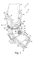
- FIG. 1 is a perspective view of one embodiment of a surgical support apparatus
- FIG. 2 is another perspective view of the surgical support apparatus of FIG. 1 ;
- FIG. 3 is a fragmentary front elevation view of the surgical support apparatus of FIG. 1 ;
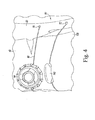
- FIG. 4 is another fragmentary front elevation view of the surgical support apparatus of FIG. 1 ;
- FIG. 5 is a fragmentary side elevation view of the surgical support apparatus of FIG. 1 ;
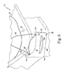
- FIG. 6 is another fragmentary side elevation view of the surgical support apparatus of FIG. 1 ;
- FIG. 7 is another fragmentary side elevation view of the surgical support apparatus of FIG. 1 showing the guide removed from the cradle;
- FIG. 8 is a fragmentary rear perspective view of the surgical support apparatus of FIG. 1 showing the cradle in profile;
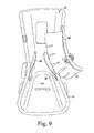
- FIG. 9 is another perspective view of the surgical support apparatus of FIG. 1 showing the rotary lacing system and the tongue unlatched;
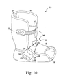
- FIG. 10 is a perspective view of another embodiment of a surgical support apparatus with a rotary lacing system
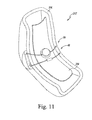
- FIG. 11 is a perspective view of another embodiment of a surgical support apparatus with a rotary lacing system
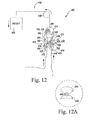
- FIG. 12 is a diagrammatic view of an embodiment of a surgical support apparatus with a rotary lacing system not in accord with the invention.
- FIG. 12A is a diagrammatic view showing the rotary lacing system and cable of the surgical support apparatus of FIG. 12 .
- Terms representing anatomical references such as anterior, posterior, medial, lateral, superior, inferior, etcetera, may be used throughout this disclosure in reference to both the surgical support apparatus described herein and a patient's natural anatomy. Such terms have well-understood meanings in both the study of anatomy and the surgical field. Use of such anatomical reference terms is intended to be consistent with their well-understood meanings unless noted otherwise.
- a surgical support apparatus 10 is shown embodied as a surgical boot 12, which is used to support a lower portion of a patient's foot and leg during a surgical procedure. It will be appreciated that the surgical support apparatus 10 may be alternatively embodied as an arm sheath that supports a portion of a patient's arm or hand, a neck brace that rigidly supports a patient's neck and head, or any other support device configured to support a portion of a patient's body.
- the surgical boot 12 includes a shell 14 and a tongue 16.
- the shell 14 is formed from rigid or semi-rigid plastic material and has a generally L-shape.
- the shell 14 has a channel 18 defined by a rim 20 that is sized to receive a lower portion of a leg 22 and a foot 24, which are wrapped in a foam pad 26.
- the channel 18 extends a depth 30; at a lower end 32, the channel 18 has a depth 34.
- the depth 30 is greater than the depth 34.
- the shell 14 also includes a pair of rigid or semi-rigid plastic flaps 36 that are secured to the channel 18.
- the tongue 16 includes a curved body 40 formed from a rigid or semi-rigid plastic material. As shown in FIGS. 1-9 , the tongue 16 and the shell 14 are formed as separate components. It should also be appreciated that in other embodiments the shell 14 and the tongue 16 may be made integral.
- the curved body 40 is shaped to fit over the anterior side of the leg 22 and the foot 24. When the leg 22 and the foot 24 are positioned in the surgical boot 12, the curved body 40 is positioned opposite the heel (not shown) of the foot 24 received in the channel 18 of the shell 14. An inner surface 42 of the curved body 40 contacts the pair of rigid or semi-rigid plastic flaps 36 of the shell 14.
- the shell 14 and the tongue 16 enclose the lower portion of the leg 22 and the foot 24 therebetween.
- the shell 14 and the tongue 16 cooperate to rigidly hold the lower portion of the leg 22 and the foot 24 within the surgical boot 12.
- the surgical boot 12 also includes a pair of tightening devices 48 configured to draw the tongue 16 toward the shell 14 such that a clamping force is applied to the lower portion of the leg 22 and the foot 24.
- the tightening device 48 positioned between the upper end 28 and the lower end 32 of the shell 14 is a rotary lacing system 50, while the tightening device 48 positioned between the rotary lacing system 50 and the upper end 28 of the shell 14 is a strap mechanism 52. It will be appreciated that in other embodiments the surgical boot 12 may include additional and/or alternative tightening devices 48.
- the rotary facing system 50 includes a rotary tightening mechanism 54, guides 56, 58, and a cable 60 coupled to the rotary tightening mechanism 54 and routed through the guides 56, 58.
- the rotary tightening mechanism 54 includes a knob 62 and a reel body 64 coupled to the curved body 40 of the tongue 16. It will be appreciated that in other embodiments the rotary tightening mechanism 54 may not be coupled to the tongue 16.
- a rotary tightening mechanism 54 is a Boa High Power Reel - Series 40 Coiler, commercially available from Boa Technology, Inc. of Steamboat Springs, CO, U.S.A. U.S. Patent No.
- the guides 56, 58 are positioned on either side of the channel 18 of the shell 14.
- the guide 56 includes a pair of holes 70, 72 that are formed in the rim 20 of the shell 14.
- the cable 60 is received through the hole 70 of the rim 20 into the interior (not shown) of the shell 14 and is guided along the back surface (not shown) of the rim 20 to the hole 72.
- the guide 56 may include a track positioned within the interior of the shell 14 between the holes 70, 72.
- the track may be formed from hardened plastic or metallic material that resists wear.
- the cable 60 passes out of the interior of the shell 14 through the hole 72 of the rim 20. It will be appreciated that in other embodiments the guide 56 may be a separate structure coupled to the shell 14.
- the guide 58 is positioned on the opposite side of the channel 18 of the shell 14. As shown in FIGS. 5-8 , the guide 58 includes a handle 80 that may be detached from a cradle 82 such that the surgical boot 12 may be removed from the lower portion of the leg 22 and the foot 24. As best seen in FIGS. 7 and 8 , the cradle 82 is a metal bracket 84 that is secured to the shell 14 by a number of fasteners 86. It will be appreciated that in other embodiments the bracket 84 may be formed from rigid or hardened plastic materials. It will be appreciated that in other embodiments the guide 68 may be formed in the rim 20 and take a form similar to that of the guide 56.
- the bracket 84 of the guide 58 has a plate 88 that is positioned adjacent to the shell 14.
- Each of the fasteners 86 extends through an opening (not shown) formed in the plate 88 and is received in a corresponding hole (not shown) formed in the shell 14.
- a mounting arm 94 extends outwardly from the plate 88 to an end 96.
- a flange 98 extends downwardly from the end 96 such that a channel 100 is defined between the flange 98 and the plate 88.
- the channel 100 is sized to receive an upper end 110 of the handle 80.
- the handle 80 includes a body 112 extending from the upper end 110 to a lower end 114.
- a track 116 is formed in the body 112 at the upper end 110 and is sized to receive and retain the cable 60 therein.
- the cable 60 is received in one end 118 of the track 116 and is guided along the length of track 116 to another end 120.
- the body 112 of the handle 80 also includes an opening 122 that extends through the body 112 between the upper end 110 and the lower end 114.
- a grip 124 is formed at the lower end 114, and the grip 124 and the opening 122 are sized to receive a hand of a user.
- the user grasps the grip 124 and pulls downward, away from the mounting arm 94.
- the handle 80 pulls the handle 80 outward, away from the shell 14, such that handle 80 is free of the cradle 82.
- the surgical boot 12 may be removed from the lower portion of the leg 22 and the foot 24.
- the cable 60 is a braided metal wire extending from an end 130 received in a mount 132 of the reel body 64 to an end 134 received in a mount 136 of the reel body 64. Extending from the end 130, the cable 60 is routed to the guide 56 and through the hole 70. The cable 60 is then guided along the interior of shell 14 and out the hole 72. As described above, the cable 60 then extends along the outer surface 138 of the curved body 40 and is received in an opening 140 of another guide 142. As shown in the embodiment of FIGS. 1-9 , the wire guide 142 is formed in the semi-rigid or rigid plastic of the curved body 40 of the tongue 16. In other embodiments the guide 142 may be formed from cloth, metal, or other material. In other embodiments, the guide 142 may also be manufactured as a separate piece and coupled the curved body 40 during assembly of the surgical boot 12.
- the cable 60 exits the guide 142 through an opening 144 and extends along the outer surface 138 of the curved body 40 before being received in the end 118 of the track 116 of the handle 80. As described above, the cable 60 is guided along the length of track 116 before exiting through the end 120. The cable 60 is then routed to the tightening mechanism 54 and the end 134 is received in the mount 136 of the reel body 64. It should also be appreciated that in other embodiments the cable 60 may follow a different path through the shell 14 and the tongue 16.
- the strap mechanism 52 is positioned between the rotary lacing system 50 and the upper end 28 of the shell 14 and is also configured to draw the tongue 16 toward the shell 14 such that a clamping force is applied to the lower portion of the leg 22 and the foot 24.
- the strap mechanism 52 includes a ladder strap 160 and a buckle 162.
- the strap 160 includes a number of teeth 164 positioned along the length of strap 160.
- the strap 160 has an end 166 that is secured to the shell 14 on the opposite side of the channel 18 from the buckle 162.
- the strap 160 extends from the end 166 over the outer surface 138 of the curved body 40 and is received in a guideway 168. As shown in FIG.
- the guideway 168 is formed in the semi-rigid or rigid plastic of the curved body 40.
- the guideway 168 may be formed from cloth, metal, or other material.
- the guideway 168 may also be manufactured as a separate piece and coupled the curved body 40 during assembly of the surgical boot 12.
- the buckle 162 includes a mounting plate 170 coupled to the shell 14.
- the mounting plate 170 includes a pair of arms 172 that extend outwardly from the mounting plate 170.
- a body 174 is rotatably coupled to the arms 172 via a pair of pivot joints 176.
- a slot 180 is defined between the plate 170 and the body 174.
- the body 174 is placed in the open position and the strap 160 is moved through the slot 180 until the lower portion of the leg 22 and the foot 24 are positioned snugly between the channel 18 of the shell 14 and the curved body 40 of the tongue 16.
- the body 174 is then placed in the closed position.
- the clasp 178 engages with the teeth 164 of the strap 160 and draws an additional length of the strap 160 through the slot 180, thereby drawing the tongue 16 toward the shell 14 and applying a clamping force to the lower portion of the leg 22 and the foot 24.
- the shell 14 and the tongue 16 cooperate to rigidly hold the lower portion of the leg 22 and the foot 24 within the surgical boot 12.
- the strap mechanism 52 may be replaced by another rotary tightening mechanism similar to rotary tightening mechanism 54. It will also be appreciated that in other embodiments the surgical boot 12 may include additional rotary tightening mechanisms 54 to apply additional clamping forces to the lower portion of the leg 22 and the foot 24.
- FIG. 10 another embodiment of a surgical boot 12 is shown (hereinafter referred to as surgical boot 212).
- surgical boot 212 includes a shell 14, a tongue 16, and a pair of tightening devices 48 configured to draw the tongue 16 toward the shell 14 such that a clamping force is applied to a lower portion of a leg and a foot.
- the tightening device 48 positioned between an upper end 28 and a lower end 32 of the shell 14 is a rotary facing system 50, while the tightening device 48 positioned between the rotary lacing system 50 and the upper end 28 of the shell 14 is a strap mechanism 52.
- the handle 220 includes a contoured grip 222 sized to receive a hand of user.
- the handle 220 also include a slot 224 formed on an upper end 226 sized to receive a cradle 228. Similar to the cradle 82 of the embodiment of FIGS. 1-9 . the cradle 228 is coupled to the shell 14.
- FIG. 11 another embodiment of a surgical boot 12 is shown (hereinafter referred to as surgical boot 312).
- surgical boot 312 includes another shell 314 and tongue 316.
- the surgical boot 312 includes only a single tightening device 48, embodied as a rotary lacing system 50, configured to draw the tongue 316 toward the shell 314 such that a clamping force is applied to a lower portion of a leg and a foot.
- a surgical support apparatus 400 not in accord with the invention is shown embodied as an arm sheath 412, which is used to support a portion of a patient's arm during a surgical procedure.
- the arm sheath 412 includes a plate 414 sized to receive a portion of an arm 416.
- the portion of the arm 416 may be wrapped in a foam pad or other protective material.
- the arm sheath 412 also includes a tightening device 430 configured to apply a clamping force to the portion of the arm 416. It will be appreciated that in other embodiments the arm sheath 412 may include additional and/or alternative tightening devices 430. As shown in FIG. 12 , the tightening device 430 is a rotary lacing system 432 including a rotary tightening mechanism 434 and a pair of cables 436, 438 coupled to the rotary tightening mechanism 434. The rotary tightening mechanism 434 includes a knob 440 and a reel body 442.
- a rotary tightening mechanism 434 is a Boa High Power Reel - Series 40 Coiler, commercially available from Boa Technology, Inc.
- Each of the cables 436, 438 is embodied as a braided metal wire. It will be appreciated that in other embodiments the cables may be formed from plastic or cloth material.
- the cable 436 extends from an end 450 received in a mount 452 of the reel body 442 to an end 454 received in another mount 456 of the reel body 442. Extending from the end 450, the cable 436 is routed under one side 460 of the plate 414 and along the back surface of the plate 414.
- the plate 414 may include a number of guides sized to receive the cable 436 and route the cable 436 around the plate 414.
- the cable 438 extends from an end 470 received in a mount 472 of the reel body 442 to an end 474 received in another mount 476 of the reel body 442. Extending from the end 470, the cable 438 is routed under one side 480 of the plate 414 and along the back surface of the plate 414.
- the plate 414 may include a number of guides sized to receive the cable 438 and route the cable 438 around the plate 414.
- the arm sheath 412 also includes a load system 490 configured to place the arm 416 in tension.
- the arm sheath 412 includes a weight 492 coupled to an end 494 of the plate 414 via a cable 496.
- a pulley 498 is positioned between the weight 492 and the plate 414 to guide the cable 496.
Landscapes
- Health & Medical Sciences (AREA)
- General Health & Medical Sciences (AREA)
- Engineering & Computer Science (AREA)
- Biomedical Technology (AREA)
- Life Sciences & Earth Sciences (AREA)
- Animal Behavior & Ethology (AREA)
- Public Health (AREA)
- Veterinary Medicine (AREA)
- Orthopedic Medicine & Surgery (AREA)
- Heart & Thoracic Surgery (AREA)
- Vascular Medicine (AREA)
- Nursing (AREA)
- Surgical Instruments (AREA)
Claims (8)
- Chirurgische Stützvorrichtung, umfassend eine chirurgische Manschette (12, 212, 312), die zur Aufnahme eines Gliedmaßes eines Patienten in ihr dimensioniert ist, wobei die chirurgische Manschette eine Schale (14, 314) und eine Zunge (16, 316) beinhaltet, und eine Spannvorrichtung (48), die zwischen einem ersten Ende und einem zweiten Ende der chirurgischen Manschette positioniert ist, wobei die Spannvorrichtung (48) zum Ziehen der Zunge (16, 316) in Richtung auf die Schale (14, 134) gestaltet ist, so dass eine Klemmkraft auf den Teil des Gliedmaßes des Patienten ausgeübt wird, der in der chirurgischen Manschette positioniert ist, und wobei die Spannvorrichtung ein Rotationsschnürsystem (50) ist, dadurch gekennzeichnet, dass das Rotationsschnürsystem (50) einen Rotationsspannmechanismus (54), ein an jedem Ende mit dem Rotationsspannmechanismus (54) verbundenes Kabel und ein Paar von zur Aufnahme des Kabels (60) dimensionierten Führungen (56, 58) umfasst.
- Chirurgische Stützvorrichtung nach Anspruch 1, wobei die Zunge (16, 316) der chirurgischen Manschette den Rotationsspannmechanismus (54) aufweist und die Schale (14, 314) das Führungspaar (56, 58) aufweist.
- Chirurgische Stützvorrichtung nach Anspruch 2, wobei der Rotationsspannmechanismus einen mit der Zunge (16, 316) verbundenen Rollenkörper (64), wobei der Rollenkörper (64) jedes Ende des Kabels (60) aufnimmt, und einen Knopf (62) aufweist, der drehend mit dem Rollenkörper (64) verbunden ist, so dass das Drehen des Knopfs (62) in einer ersten Richtung jedes Ende des Kabels (60) in den Rollenkörper (64) zieht und die Zunge (16, 316) in Richtung auf die Schale (14, 314) zieht.
- Chirurgische Stützvorrichtung nach Anspruch 2, wobei eine erste Führung (58) des Führungspaares eine mit der Schale (14) verbundene Wiege (82) und einen abnehmbar mit der Wiege (82) verbundenen Griff (80) aufweist, wobei der Griff (80) eine in ihm definierte Nut (116) aufweist, die zur Aufnahme des Kabels (60) dimensioniert ist.
- Chirurgische Stützvorrichtung nach einem der vorhergehenden Ansprüche, die ferner eine zweite Spannvorrichtung (48) aufweist, die zwischen der Spannvorrichtung (48) und dem ersten Ende der chirurgischen Manschette (12, 212) positioniert ist.
- Chirurgische Stützvorrichtung nach Anspruch 5, wobei die zweite Spannvorrichtung ein Riemenmechanismus (52) ist.
- Chirurgische Stützvorrichtung nach Anspruch 6, wobei der Riemenmechanismus einen Zahnriemen (160), der über die Zunge (16) der chirurgischen Manschette verläuft, und eine Schnalle (162), die mit der Schale (14) der chirurgischen Manschette verbunden ist, beinhaltet, wobei die Schnalle (162) zur Aufnahme des Zahnriemens (160) dimensioniert ist.
- Chirurgische Stützvorrichtung nach Anspruch 7, wobei der Zahnriemen (160) eine Vielzahl von Zähnen (164) hat und die Schnalle (162) eine Schließe (178) aufweist, die gestaltet ist, um mit der Vielzahl von Zähnen (164) in Eingriff zu kommen, um die Zunge (16) in Richtung auf die Schale (14) zu ziehen.
Applications Claiming Priority (1)
| Application Number | Priority Date | Filing Date | Title |
|---|---|---|---|
| US30490310P | 2010-02-16 | 2010-02-16 |
Publications (2)
| Publication Number | Publication Date |
|---|---|
| EP2363100A1 EP2363100A1 (de) | 2011-09-07 |
| EP2363100B1 true EP2363100B1 (de) | 2013-05-01 |
Family
ID=44188018
Family Applications (1)
| Application Number | Title | Priority Date | Filing Date |
|---|---|---|---|
| EP11154689.1A Active EP2363100B1 (de) | 2010-02-16 | 2011-02-16 | Schnürsystem zur Sicherung eines Gliedmaßes in einer chirurgischen Stützvorrichtung |
Country Status (2)
| Country | Link |
|---|---|
| US (1) | US8707486B2 (de) |
| EP (1) | EP2363100B1 (de) |
Cited By (1)
| Publication number | Priority date | Publication date | Assignee | Title |
|---|---|---|---|---|
| EP3790522B1 (de) * | 2018-05-07 | 2022-03-30 | Condor Medtec GmbH | Extensions-fussmanschette |
Families Citing this family (85)
| Publication number | Priority date | Publication date | Assignee | Title |
|---|---|---|---|---|
| US20060156517A1 (en) | 1997-08-22 | 2006-07-20 | Hammerslag Gary R | Reel based closure system |
| CN101193568B (zh) * | 2004-10-29 | 2011-11-30 | 博技术有限公司 | 基于卷轴的闭合系统及使用该系统的鞋类物品 |
| EP2237692B1 (de) | 2008-01-18 | 2015-01-07 | Boa Technology, Inc. | Verschlusssystem |
| CN102026594B (zh) | 2008-05-15 | 2013-12-25 | 欧苏尔公司 | 利用旋转式拉紧的矫形装置 |
| US8469372B2 (en) | 2008-10-23 | 2013-06-25 | Bryce M. Kloster | Splitboard binding apparatus |
| EP2378911B1 (de) | 2008-11-21 | 2014-05-21 | Boa Technology, Inc. | Schnürverschluss auf spulengrundlage |
| WO2011091325A1 (en) | 2010-01-21 | 2011-07-28 | Boa Technology, Inc. | Guides for lacing systems |
| US8707486B2 (en) * | 2010-02-16 | 2014-04-29 | Allen Medical Systems, Inc. | Lacing system to secure a limb in a surgical support apparatus |
| US10070695B2 (en) | 2010-04-30 | 2018-09-11 | Boa Technology Inc. | Tightening mechanisms and applications including the same |
| KR102269934B1 (ko) | 2010-04-30 | 2021-06-25 | 보아 테크놀러지, 인크. | 릴 기반 끈 조임 시스템 |
| US9375053B2 (en) | 2012-03-15 | 2016-06-28 | Boa Technology, Inc. | Tightening mechanisms and applications including the same |
| WO2012003399A2 (en) | 2010-07-01 | 2012-01-05 | Boa Technology, Inc. | Lace guide |
| US8920353B2 (en) | 2011-05-16 | 2014-12-30 | Orthotic Solutions, Llc | Adjustable lumbo-sacral orthosis |
| US9381130B2 (en) * | 2011-06-02 | 2016-07-05 | Allen Medical Systems, Inc. | Surgical foot support with tightener system |
| US9655764B2 (en) | 2011-06-02 | 2017-05-23 | Allen Medical Systems, Inc. | Surgical foot support with handles |
| US9101181B2 (en) | 2011-10-13 | 2015-08-11 | Boa Technology Inc. | Reel-based lacing system |
| US9078490B2 (en) * | 2011-11-29 | 2015-07-14 | Nike, Inc. | Ankle and foot support system |
| US8747340B2 (en) * | 2011-11-29 | 2014-06-10 | Nike, Inc. | Ankle and foot support system |
| US9238168B2 (en) | 2012-02-10 | 2016-01-19 | Bryce M. Kloster | Splitboard joining device |
| US9179729B2 (en) | 2012-03-13 | 2015-11-10 | Boa Technology, Inc. | Tightening systems |
| US9266010B2 (en) | 2012-06-12 | 2016-02-23 | Tyler G. Kloster | Splitboard binding with adjustable leverage devices |
| US9532893B2 (en) | 2012-08-31 | 2017-01-03 | Nike, Inc. | Motorized tensioning system |
| US9516923B2 (en) | 2012-11-02 | 2016-12-13 | Boa Technology Inc. | Coupling members for closure devices and systems |
| EP2916680B1 (de) | 2012-11-06 | 2018-12-26 | Boa Technology Inc. | Vorrichtungen und verfahren zur einstellung der passform von schuhen |
| EP2948014B1 (de) | 2013-01-28 | 2019-06-26 | Boa Technology Inc. | Riemenfixieranordnung und system |
| WO2014124054A1 (en) | 2013-02-05 | 2014-08-14 | Boa Technology Inc. | Closure devices for medical devices and methods |
| US10251451B2 (en) | 2013-03-05 | 2019-04-09 | Boa Technology Inc. | Closure devices including incremental release mechanisms and methods therefor |
| US9610185B2 (en) | 2013-03-05 | 2017-04-04 | Boa Technology Inc. | Systems, methods, and devices for automatic closure of medical devices |
| WO2014159706A2 (en) * | 2013-03-14 | 2014-10-02 | Kci Licensing, Inc. | Compression therapy apparatus, system and method |
| KR20260030757A (ko) | 2013-04-01 | 2026-03-06 | 보아 테크놀러지, 인크. | 릴 기반의 폐쇄 시스템을 포함하도록 신발류를 개장하기 위한 방법 및 장치 |
| US10076160B2 (en) | 2013-06-05 | 2018-09-18 | Boa Technology Inc. | Integrated closure device components and methods |
| PL4427621T3 (pl) | 2013-06-05 | 2026-03-16 | Boa Technology Inc. | Komponenty i sposoby związane ze zintegrowanymi urządzeniami zamykającymi |
| JP6105404B2 (ja) | 2013-06-18 | 2017-03-29 | 株式会社ジャパーナ | 靴紐巻取用リール |
| JP6087219B2 (ja) * | 2013-06-18 | 2017-03-01 | 株式会社ジャパーナ | 靴紐巻取装置 |
| US9629417B2 (en) | 2013-07-02 | 2017-04-25 | Boa Technology Inc. | Tension limiting mechanisms for closure devices and methods therefor |
| EP3019043B1 (de) | 2013-07-10 | 2019-09-18 | Boa Technology Inc. | Verschlussvorrichtungen mit inkrementellen lösemechanismen und verfahren dafür |
| WO2015035257A2 (en) | 2013-09-05 | 2015-03-12 | Boa Technology Inc. | Alternative lacing guides for tightening mechanisms and methods therefor |
| KR102350912B1 (ko) | 2013-09-13 | 2022-01-13 | 보아 테크놀러지, 인크. | 릴 기반 폐쇄 장치 및 그에 따른 방법 |
| KR101895140B1 (ko) | 2013-11-18 | 2018-09-04 | 보아 테크놀러지, 인크. | 보철 및 장구의 자동 폐쇄를 제공하기 위한 방법 및 장치 |
| USD835976S1 (en) | 2014-01-16 | 2018-12-18 | Boa Technology Inc. | Coupling member |
| AU2015229719B2 (en) | 2014-03-10 | 2017-04-06 | Stryker Corporation | Limb positioning system |
| US9763808B2 (en) | 2014-05-19 | 2017-09-19 | Ossur Hf | Adjustable prosthetic device |
| US10512305B2 (en) | 2014-07-11 | 2019-12-24 | Ossur Hf | Tightening system with a tension control mechanism |
| USD751281S1 (en) | 2014-08-12 | 2016-03-15 | Boa Technology, Inc. | Footwear tightening reels |
| USD767269S1 (en) | 2014-08-26 | 2016-09-27 | Boa Technology Inc. | Footwear tightening reel |
| US20160058127A1 (en) | 2014-08-28 | 2016-03-03 | Boa Technology Inc. | Devices and methods for enhancing the fit of boots and other footwear |
| USD758061S1 (en) | 2014-09-08 | 2016-06-07 | Boa Technology, Inc. | Lace tightening device |
| WO2016054317A1 (en) | 2014-10-01 | 2016-04-07 | Ossur Hf | Support for articles and methods for using the same |
| WO2016057697A1 (en) | 2014-10-07 | 2016-04-14 | Boa Technology Inc. | A tension adjustment mechanism and a method for adjusting the fit of a shoe |
| US10188573B2 (en) | 2014-11-05 | 2019-01-29 | Allen Medical Systems, Inc. | Boot stirrup |
| USD776421S1 (en) | 2015-01-16 | 2017-01-17 | Boa Technology, Inc. | In-footwear lace tightening reel |
| USD835898S1 (en) | 2015-01-16 | 2018-12-18 | Boa Technology Inc. | Footwear lace tightening reel stabilizer |
| US9951904B2 (en) | 2015-03-24 | 2018-04-24 | Stryker Corporation | Rotatable seat clamps for rail clamp |
| CN106151780B (zh) * | 2015-04-08 | 2018-11-02 | 蔡志信 | 固定框架 |
| US10029165B2 (en) | 2015-04-27 | 2018-07-24 | Bryce M. Kloster | Splitboard joining device |
| US9604122B2 (en) | 2015-04-27 | 2017-03-28 | Bryce M. Kloster | Splitboard joining device |
| US11382816B2 (en) | 2015-06-05 | 2022-07-12 | Stryker Corporation | Surgical table and accessories to facilitate hip arthroscopy |
| US10004297B2 (en) | 2015-10-15 | 2018-06-26 | Boa Technology Inc. | Lacing configurations for footwear |
| USD788446S1 (en) * | 2015-10-23 | 2017-06-06 | Airtox International A/S | Locking device for shoes |
| US10561514B2 (en) | 2015-12-10 | 2020-02-18 | Ossur Iceland Ehf | Orthotic system |
| US10827804B2 (en) * | 2016-03-15 | 2020-11-10 | Nike, Inc. | Lacing apparatus for automated footwear platform |
| JP7073335B2 (ja) | 2016-08-02 | 2022-05-23 | ボア テクノロジー,インコーポレイテッド | 紐締めシステムの張力部材ガイド |
| KR102822775B1 (ko) | 2016-12-09 | 2025-06-20 | 보아 테크놀러지, 인크. | 릴 기반의 폐쇄 시스템 |
| US11559455B2 (en) | 2017-02-06 | 2023-01-24 | Stryker Corp. | Distraction frame for effecting hip distraction |
| AU2018214679A1 (en) | 2017-02-06 | 2019-08-29 | Stryker Corp. | Method and apparatus for supporting and stabilizing a patient during hip distraction |
| US11510805B2 (en) | 2017-02-06 | 2022-11-29 | Stryker Corp. | Anatomical gripping system for gripping the leg and foot of a patient when effecting hip distraction and/or when effecting leg positioning |
| US10543630B2 (en) | 2017-02-27 | 2020-01-28 | Boa Technology Inc. | Reel based closure system employing a friction based tension mechanism |
| US11357279B2 (en) | 2017-05-09 | 2022-06-14 | Boa Technology Inc. | Closure components for a helmet layer and methods for installing same |
| CN114304812B (zh) * | 2017-05-31 | 2024-11-26 | 耐克创新有限合伙公司 | 自动鞋系鞋带系统、装置及技术 |
| KR101894716B1 (ko) * | 2017-06-30 | 2018-09-04 | 이동렬 | 의료용 다리 부목 |
| US12396520B2 (en) | 2017-07-18 | 2025-08-26 | Boa Technology Inc. | Configurations for footwear employing reel based closure systems |
| US10772384B2 (en) | 2017-07-18 | 2020-09-15 | Boa Technology Inc. | System and methods for minimizing dynamic lace movement |
| USD878836S1 (en) | 2017-08-17 | 2020-03-24 | Stryker Corp. | Table extender |
| US11234885B2 (en) | 2018-02-20 | 2022-02-01 | Allen Medical Systems, Inc. | Adjustable lithotomy positioning apparatus with a limb rest |
| US11524188B2 (en) | 2018-10-09 | 2022-12-13 | Checkmate Lifting & Safety Ltd | Tensioning device |
| GB201818169D0 (en) * | 2018-11-07 | 2018-12-19 | Greater Glasgow Healthboard | Motion restriction device |
| EP4678055A3 (de) | 2019-02-01 | 2026-04-15 | Boa Technology, Inc. | Auf rollen basierende verschlussvorrichtungen zum festziehen eines skischuhes |
| CN109907868A (zh) * | 2019-04-02 | 2019-06-21 | 董冬香 | 固定保护器 |
| CN114072024B (zh) | 2019-05-01 | 2024-08-20 | Boa科技股份有限公司 | 基于卷轴的闭合系统 |
| US11117042B2 (en) | 2019-05-03 | 2021-09-14 | Bryce M. Kloster | Splitboard binding |
| US11925572B2 (en) * | 2020-01-08 | 2024-03-12 | DOXA Medical, LLC | Lower leg orthotic brace |
| US11564855B2 (en) | 2020-09-28 | 2023-01-31 | Stryker Corporation | Systems and methods for supporting and stabilizing a patient during hip distraction |
| US11938394B2 (en) | 2021-02-22 | 2024-03-26 | Bryce M. Kloster | Splitboard joining device |
| CN113143567B (zh) * | 2021-02-24 | 2022-07-29 | 汪文 | 一种用于病人约束的限位保护和康复装置 |
| US12295894B2 (en) | 2021-11-09 | 2025-05-13 | Allen Medical Systems, Inc. | Surgical traction boot having resilient heel pad and medial and lateral straps |
Family Cites Families (13)
| Publication number | Priority date | Publication date | Assignee | Title |
|---|---|---|---|---|
| US4573482A (en) * | 1982-07-02 | 1986-03-04 | Arthro-Medic, Inc. | Arthroscopic surgery method |
| CH650387A5 (de) * | 1982-12-27 | 1985-07-31 | Raichle Sportschuh Ag | Sportschuh, insbesondere skischuh. |
| DE3317771A1 (de) * | 1983-04-26 | 1984-10-31 | Weinmann Gmbh & Co Kg Fahrrad- Und Motorrad-Teilefabrik, 7700 Singen | Skischuh mit zentralverschluss |
| US4620698A (en) * | 1985-03-04 | 1986-11-04 | Professional Medical Products, Inc. | Orthopedic support device |
| US4886258A (en) * | 1988-08-24 | 1989-12-12 | Scott James W | Well leg operative support |
| US5177882A (en) * | 1989-06-03 | 1993-01-12 | Puma Ag Rudolf Dassler Sport | Shoe with a central fastener |
| US5052128A (en) * | 1989-07-24 | 1991-10-01 | Robert Lonardo | Padded boot means for invalid patients |
| US5249377A (en) * | 1990-01-30 | 1993-10-05 | Raichle Sportschuh Ag | Ski boot having tensioning means in the forefoot region |
| US6289558B1 (en) * | 1997-08-22 | 2001-09-18 | Boa Technology, Inc. | Footwear lacing system |
| US7591050B2 (en) * | 1997-08-22 | 2009-09-22 | Boa Technology, Inc. | Footwear lacing system |
| US6234173B1 (en) * | 1999-09-28 | 2001-05-22 | Mohammed Ali Hajianpour | Foot restraint apparatus for holding a leg in place during knee surgery |
| US6681772B2 (en) * | 2001-09-24 | 2004-01-27 | Kim A. Atwater | Hand, wrist and forearm device patients during surgery |
| US8707486B2 (en) * | 2010-02-16 | 2014-04-29 | Allen Medical Systems, Inc. | Lacing system to secure a limb in a surgical support apparatus |
-
2011
- 2011-02-15 US US13/027,413 patent/US8707486B2/en active Active
- 2011-02-16 EP EP11154689.1A patent/EP2363100B1/de active Active
Cited By (1)
| Publication number | Priority date | Publication date | Assignee | Title |
|---|---|---|---|---|
| EP3790522B1 (de) * | 2018-05-07 | 2022-03-30 | Condor Medtec GmbH | Extensions-fussmanschette |
Also Published As
| Publication number | Publication date |
|---|---|
| EP2363100A1 (de) | 2011-09-07 |
| US8707486B2 (en) | 2014-04-29 |
| US20110197362A1 (en) | 2011-08-18 |
Similar Documents
| Publication | Publication Date | Title |
|---|---|---|
| US8707486B2 (en) | Lacing system to secure a limb in a surgical support apparatus | |
| EP2508152B1 (de) | Distraktorriemen zur Verwendung mit Distraktorvorrichtungen | |
| JP6185600B2 (ja) | 履物用の引き締めシステム | |
| US9339693B1 (en) | Weight lifting strap with equipment engagement system | |
| EP2529719B1 (de) | Chirurgische Fußstütze mit Spannsystem | |
| KR102017858B1 (ko) | 정형외과용 가압 장치 | |
| US20170367423A1 (en) | Headband for virtual reality goggles | |
| US4807876A (en) | Lift/tow assistance device to relieve the lower arm in sporting activities using equipments | |
| KR20150135382A (ko) | 잠금식 스트랩을 구비한 부츠 | |
| JP4918635B2 (ja) | 内視鏡格納装置 | |
| US9427350B1 (en) | Ankle support with cable reel | |
| US20240049833A1 (en) | Single-pull tightened snowshoe binding | |
| JP2007537010A5 (de) | ||
| US20110059828A1 (en) | A k pac | |
| CN108289522A (zh) | 具有可释放发孔的头盔贴合调节系统 | |
| JP2005013739A (ja) | 歩行用の杖、スキーのストック、ハイキング用の杖等の握り部に取り付けるストラップの固定、迅速な解除、安全な取り外し、かつ調節に用いる装置 | |
| US10105588B1 (en) | Snowboard binding with adjustment memory | |
| JPH01236001A (ja) | 特にスキー・ブーツ用のブーツを閉じて足を確保する装置 | |
| US20140367952A1 (en) | Hand strap for a skiing pole or similar | |
| US11330924B2 (en) | Device and method for aiding putting on a ski boot | |
| EP2384169B1 (de) | Bruststützgürtel | |
| US11497982B1 (en) | Ski pole retention and storage apparatus | |
| CA2802384C (en) | Goalie toe hook | |
| EP3838063B1 (de) | Skiträgersystem | |
| US20240367026A1 (en) | Apparatus for storage, protection, or transport of sporting devices |
Legal Events
| Date | Code | Title | Description |
|---|---|---|---|
| PUAI | Public reference made under article 153(3) epc to a published international application that has entered the european phase |
Free format text: ORIGINAL CODE: 0009012 |
|
| AK | Designated contracting states |
Kind code of ref document: A1 Designated state(s): AL AT BE BG CH CY CZ DE DK EE ES FI FR GB GR HR HU IE IS IT LI LT LU LV MC MK MT NL NO PL PT RO RS SE SI SK SM TR |
|
| AX | Request for extension of the european patent |
Extension state: BA ME |
|
| 17P | Request for examination filed |
Effective date: 20120306 |
|
| GRAP | Despatch of communication of intention to grant a patent |
Free format text: ORIGINAL CODE: EPIDOSNIGR1 |
|
| GRAS | Grant fee paid |
Free format text: ORIGINAL CODE: EPIDOSNIGR3 |
|
| GRAA | (expected) grant |
Free format text: ORIGINAL CODE: 0009210 |
|
| AK | Designated contracting states |
Kind code of ref document: B1 Designated state(s): AL AT BE BG CH CY CZ DE DK EE ES FI FR GB GR HR HU IE IS IT LI LT LU LV MC MK MT NL NO PL PT RO RS SE SI SK SM TR |
|
| REG | Reference to a national code |
Ref country code: GB Ref legal event code: FG4D |
|
| REG | Reference to a national code |
Ref country code: CH Ref legal event code: EP Ref country code: AT Ref legal event code: REF Ref document number: 609415 Country of ref document: AT Kind code of ref document: T Effective date: 20130515 |
|
| REG | Reference to a national code |
Ref country code: IE Ref legal event code: FG4D |
|
| REG | Reference to a national code |
Ref country code: DE Ref legal event code: R096 Ref document number: 602011001485 Country of ref document: DE Effective date: 20130704 |
|
| REG | Reference to a national code |
Ref country code: AT Ref legal event code: MK05 Ref document number: 609415 Country of ref document: AT Kind code of ref document: T Effective date: 20130501 |
|
| REG | Reference to a national code |
Ref country code: NL Ref legal event code: VDEP Effective date: 20130501 |
|
| REG | Reference to a national code |
Ref country code: LT Ref legal event code: MG4D |
|
| PG25 | Lapsed in a contracting state [announced via postgrant information from national office to epo] |
Ref country code: SI Free format text: LAPSE BECAUSE OF FAILURE TO SUBMIT A TRANSLATION OF THE DESCRIPTION OR TO PAY THE FEE WITHIN THE PRESCRIBED TIME-LIMIT Effective date: 20130501 Ref country code: ES Free format text: LAPSE BECAUSE OF FAILURE TO SUBMIT A TRANSLATION OF THE DESCRIPTION OR TO PAY THE FEE WITHIN THE PRESCRIBED TIME-LIMIT Effective date: 20130812 Ref country code: AT Free format text: LAPSE BECAUSE OF FAILURE TO SUBMIT A TRANSLATION OF THE DESCRIPTION OR TO PAY THE FEE WITHIN THE PRESCRIBED TIME-LIMIT Effective date: 20130501 Ref country code: IS Free format text: LAPSE BECAUSE OF FAILURE TO SUBMIT A TRANSLATION OF THE DESCRIPTION OR TO PAY THE FEE WITHIN THE PRESCRIBED TIME-LIMIT Effective date: 20130901 Ref country code: SE Free format text: LAPSE BECAUSE OF FAILURE TO SUBMIT A TRANSLATION OF THE DESCRIPTION OR TO PAY THE FEE WITHIN THE PRESCRIBED TIME-LIMIT Effective date: 20130501 Ref country code: LT Free format text: LAPSE BECAUSE OF FAILURE TO SUBMIT A TRANSLATION OF THE DESCRIPTION OR TO PAY THE FEE WITHIN THE PRESCRIBED TIME-LIMIT Effective date: 20130501 Ref country code: FI Free format text: LAPSE BECAUSE OF FAILURE TO SUBMIT A TRANSLATION OF THE DESCRIPTION OR TO PAY THE FEE WITHIN THE PRESCRIBED TIME-LIMIT Effective date: 20130501 Ref country code: PT Free format text: LAPSE BECAUSE OF FAILURE TO SUBMIT A TRANSLATION OF THE DESCRIPTION OR TO PAY THE FEE WITHIN THE PRESCRIBED TIME-LIMIT Effective date: 20130902 Ref country code: NO Free format text: LAPSE BECAUSE OF FAILURE TO SUBMIT A TRANSLATION OF THE DESCRIPTION OR TO PAY THE FEE WITHIN THE PRESCRIBED TIME-LIMIT Effective date: 20130801 Ref country code: GR Free format text: LAPSE BECAUSE OF FAILURE TO SUBMIT A TRANSLATION OF THE DESCRIPTION OR TO PAY THE FEE WITHIN THE PRESCRIBED TIME-LIMIT Effective date: 20130802 |
|
| PG25 | Lapsed in a contracting state [announced via postgrant information from national office to epo] |
Ref country code: CY Free format text: LAPSE BECAUSE OF FAILURE TO SUBMIT A TRANSLATION OF THE DESCRIPTION OR TO PAY THE FEE WITHIN THE PRESCRIBED TIME-LIMIT Effective date: 20130501 Ref country code: PL Free format text: LAPSE BECAUSE OF FAILURE TO SUBMIT A TRANSLATION OF THE DESCRIPTION OR TO PAY THE FEE WITHIN THE PRESCRIBED TIME-LIMIT Effective date: 20130501 Ref country code: RS Free format text: LAPSE BECAUSE OF FAILURE TO SUBMIT A TRANSLATION OF THE DESCRIPTION OR TO PAY THE FEE WITHIN THE PRESCRIBED TIME-LIMIT Effective date: 20130501 Ref country code: HR Free format text: LAPSE BECAUSE OF FAILURE TO SUBMIT A TRANSLATION OF THE DESCRIPTION OR TO PAY THE FEE WITHIN THE PRESCRIBED TIME-LIMIT Effective date: 20130501 Ref country code: BG Free format text: LAPSE BECAUSE OF FAILURE TO SUBMIT A TRANSLATION OF THE DESCRIPTION OR TO PAY THE FEE WITHIN THE PRESCRIBED TIME-LIMIT Effective date: 20130801 |
|
| PG25 | Lapsed in a contracting state [announced via postgrant information from national office to epo] |
Ref country code: LV Free format text: LAPSE BECAUSE OF FAILURE TO SUBMIT A TRANSLATION OF THE DESCRIPTION OR TO PAY THE FEE WITHIN THE PRESCRIBED TIME-LIMIT Effective date: 20130501 |
|
| PG25 | Lapsed in a contracting state [announced via postgrant information from national office to epo] |
Ref country code: SK Free format text: LAPSE BECAUSE OF FAILURE TO SUBMIT A TRANSLATION OF THE DESCRIPTION OR TO PAY THE FEE WITHIN THE PRESCRIBED TIME-LIMIT Effective date: 20130501 Ref country code: DK Free format text: LAPSE BECAUSE OF FAILURE TO SUBMIT A TRANSLATION OF THE DESCRIPTION OR TO PAY THE FEE WITHIN THE PRESCRIBED TIME-LIMIT Effective date: 20130501 Ref country code: EE Free format text: LAPSE BECAUSE OF FAILURE TO SUBMIT A TRANSLATION OF THE DESCRIPTION OR TO PAY THE FEE WITHIN THE PRESCRIBED TIME-LIMIT Effective date: 20130501 Ref country code: CZ Free format text: LAPSE BECAUSE OF FAILURE TO SUBMIT A TRANSLATION OF THE DESCRIPTION OR TO PAY THE FEE WITHIN THE PRESCRIBED TIME-LIMIT Effective date: 20130501 Ref country code: BE Free format text: LAPSE BECAUSE OF FAILURE TO SUBMIT A TRANSLATION OF THE DESCRIPTION OR TO PAY THE FEE WITHIN THE PRESCRIBED TIME-LIMIT Effective date: 20130501 |
|
| PG25 | Lapsed in a contracting state [announced via postgrant information from national office to epo] |
Ref country code: NL Free format text: LAPSE BECAUSE OF FAILURE TO SUBMIT A TRANSLATION OF THE DESCRIPTION OR TO PAY THE FEE WITHIN THE PRESCRIBED TIME-LIMIT Effective date: 20130501 Ref country code: IT Free format text: LAPSE BECAUSE OF FAILURE TO SUBMIT A TRANSLATION OF THE DESCRIPTION OR TO PAY THE FEE WITHIN THE PRESCRIBED TIME-LIMIT Effective date: 20130501 Ref country code: RO Free format text: LAPSE BECAUSE OF FAILURE TO SUBMIT A TRANSLATION OF THE DESCRIPTION OR TO PAY THE FEE WITHIN THE PRESCRIBED TIME-LIMIT Effective date: 20130501 |
|
| PLBE | No opposition filed within time limit |
Free format text: ORIGINAL CODE: 0009261 |
|
| STAA | Information on the status of an ep patent application or granted ep patent |
Free format text: STATUS: NO OPPOSITION FILED WITHIN TIME LIMIT |
|
| 26N | No opposition filed |
Effective date: 20140204 |
|
| REG | Reference to a national code |
Ref country code: DE Ref legal event code: R097 Ref document number: 602011001485 Country of ref document: DE Effective date: 20140204 |
|
| PG25 | Lapsed in a contracting state [announced via postgrant information from national office to epo] |
Ref country code: MC Free format text: LAPSE BECAUSE OF FAILURE TO SUBMIT A TRANSLATION OF THE DESCRIPTION OR TO PAY THE FEE WITHIN THE PRESCRIBED TIME-LIMIT Effective date: 20130501 Ref country code: LU Free format text: LAPSE BECAUSE OF FAILURE TO SUBMIT A TRANSLATION OF THE DESCRIPTION OR TO PAY THE FEE WITHIN THE PRESCRIBED TIME-LIMIT Effective date: 20140216 |
|
| REG | Reference to a national code |
Ref country code: CH Ref legal event code: PL |
|
| PG25 | Lapsed in a contracting state [announced via postgrant information from national office to epo] |
Ref country code: LI Free format text: LAPSE BECAUSE OF NON-PAYMENT OF DUE FEES Effective date: 20140228 Ref country code: CH Free format text: LAPSE BECAUSE OF NON-PAYMENT OF DUE FEES Effective date: 20140228 |
|
| REG | Reference to a national code |
Ref country code: IE Ref legal event code: MM4A |
|
| PG25 | Lapsed in a contracting state [announced via postgrant information from national office to epo] |
Ref country code: IE Free format text: LAPSE BECAUSE OF NON-PAYMENT OF DUE FEES Effective date: 20140216 |
|
| REG | Reference to a national code |
Ref country code: FR Ref legal event code: PLFP Year of fee payment: 6 |
|
| PG25 | Lapsed in a contracting state [announced via postgrant information from national office to epo] |
Ref country code: MT Free format text: LAPSE BECAUSE OF FAILURE TO SUBMIT A TRANSLATION OF THE DESCRIPTION OR TO PAY THE FEE WITHIN THE PRESCRIBED TIME-LIMIT Effective date: 20130501 |
|
| PG25 | Lapsed in a contracting state [announced via postgrant information from national office to epo] |
Ref country code: SM Free format text: LAPSE BECAUSE OF FAILURE TO SUBMIT A TRANSLATION OF THE DESCRIPTION OR TO PAY THE FEE WITHIN THE PRESCRIBED TIME-LIMIT Effective date: 20130501 |
|
| PG25 | Lapsed in a contracting state [announced via postgrant information from national office to epo] |
Ref country code: TR Free format text: LAPSE BECAUSE OF FAILURE TO SUBMIT A TRANSLATION OF THE DESCRIPTION OR TO PAY THE FEE WITHIN THE PRESCRIBED TIME-LIMIT Effective date: 20130501 Ref country code: HU Free format text: LAPSE BECAUSE OF FAILURE TO SUBMIT A TRANSLATION OF THE DESCRIPTION OR TO PAY THE FEE WITHIN THE PRESCRIBED TIME-LIMIT; INVALID AB INITIO Effective date: 20110216 |
|
| REG | Reference to a national code |
Ref country code: FR Ref legal event code: PLFP Year of fee payment: 7 |
|
| REG | Reference to a national code |
Ref country code: FR Ref legal event code: PLFP Year of fee payment: 8 |
|
| PG25 | Lapsed in a contracting state [announced via postgrant information from national office to epo] |
Ref country code: MK Free format text: LAPSE BECAUSE OF FAILURE TO SUBMIT A TRANSLATION OF THE DESCRIPTION OR TO PAY THE FEE WITHIN THE PRESCRIBED TIME-LIMIT Effective date: 20130501 |
|
| PG25 | Lapsed in a contracting state [announced via postgrant information from national office to epo] |
Ref country code: AL Free format text: LAPSE BECAUSE OF FAILURE TO SUBMIT A TRANSLATION OF THE DESCRIPTION OR TO PAY THE FEE WITHIN THE PRESCRIBED TIME-LIMIT Effective date: 20130501 |
|
| P01 | Opt-out of the competence of the unified patent court (upc) registered |
Effective date: 20230512 |
|
| REG | Reference to a national code |
Ref country code: DE Ref legal event code: R082 Ref document number: 602011001485 Country of ref document: DE Representative=s name: MAIWALD GMBH, DE |
|
| PGFP | Annual fee paid to national office [announced via postgrant information from national office to epo] |
Ref country code: DE Payment date: 20250122 Year of fee payment: 15 |
|
| PGFP | Annual fee paid to national office [announced via postgrant information from national office to epo] |
Ref country code: FR Payment date: 20250122 Year of fee payment: 15 |
|
| PGFP | Annual fee paid to national office [announced via postgrant information from national office to epo] |
Ref country code: GB Payment date: 20250124 Year of fee payment: 15 |