EP2363033A1 - Protector for shoes - Google Patents
Protector for shoes Download PDFInfo
- Publication number
- EP2363033A1 EP2363033A1 EP10155484A EP10155484A EP2363033A1 EP 2363033 A1 EP2363033 A1 EP 2363033A1 EP 10155484 A EP10155484 A EP 10155484A EP 10155484 A EP10155484 A EP 10155484A EP 2363033 A1 EP2363033 A1 EP 2363033A1
- Authority
- EP
- European Patent Office
- Prior art keywords
- protector
- shoe
- lacing
- front part
- lace
- Prior art date
- Legal status (The legal status is an assumption and is not a legal conclusion. Google has not performed a legal analysis and makes no representation as to the accuracy of the status listed.)
- Granted
Links
Images
Classifications
-
- A—HUMAN NECESSITIES
- A43—FOOTWEAR
- A43B—CHARACTERISTIC FEATURES OF FOOTWEAR; PARTS OF FOOTWEAR
- A43B23/00—Uppers; Boot legs; Stiffeners; Other single parts of footwear
- A43B23/26—Tongues for shoes
-
- A—HUMAN NECESSITIES
- A43—FOOTWEAR
- A43B—CHARACTERISTIC FEATURES OF FOOTWEAR; PARTS OF FOOTWEAR
- A43B19/00—Shoe-shaped inserts; Inserts covering the instep
-
- A—HUMAN NECESSITIES
- A43—FOOTWEAR
- A43B—CHARACTERISTIC FEATURES OF FOOTWEAR; PARTS OF FOOTWEAR
- A43B7/00—Footwear with health or hygienic arrangements
- A43B7/32—Footwear with health or hygienic arrangements with shock-absorbing means
Abstract
Description
Die vorliegende Erfindung betrifft einen Protektor für Schuhe, wie beispielsweise Arbeitsschuhe oder Feuerwehrstiefel, und insbesondere einen Protektor für einen Schuh mit einem Schaft und einer Schnürung sowie einen mit einem solchen Protektor versehenen Schuh.The present invention relates to a protector for shoes, such as work shoes or firefighting boots, and more particularly to a protector for a shoe with a shaft and lacing and a shoe provided with such a protector.
Arbeitsschuhe oder Feuerwehrstiefel sind bei ihrer bestimmungsgemäßen Benutzung zahlreichen Einwirkungen ausgesetzt und idealer weise so hergestellt, dass sie dem Träger einen gewissen Schutz vor diesen Einwirkungen bieten. Dazu weisen Arbeitsschuhe typischerweise eine Stahlkappe an der Vorderseite des Schuhs sowie weitere eingearbeitete Verstärkungen auf, wie beispielsweise an den Knöcheln und der Hinterkappe. Ferner können Arbeitsschuhe verstärkte Sohlen aufweisen. Derartige, fest integrierte Verstärkungen sind teilweise durch Schutzverordnungen vorgeschrieben und haben sich als vorteilhaft herausgestellt, da sie einen verbesserten Schutz der entsprechenden Fuß- und Beinpartien gewährleisten.Work shoes or firefighting boots, when used as intended, are subject to numerous actions and are ideally made to provide the wearer with some protection against these effects. For this purpose, work shoes typically have a steel toe on the front of the shoe as well as other incorporated reinforcements, such as at the ankles and the rear cap. Furthermore, work shoes may have reinforced soles. Such integral reinforcements are in part prescribed by protective regulations and have been found to be advantageous, as they ensure improved protection of the corresponding leg and leg sections.
Bisher relativ ungeschützt blieben jedoch empfindliche und besonders ausgesetzte Partien des Fußes, wie beispielsweise das Schienbein und der Fußrücken sowie entsprechende Teile des Schuhs auf dessen Vorderseite. Häufig befindet sich gerade an diesen ausgesetzten Partien des Schuhs die Schnürung oder der Reißverschluss, die im Vergleich zu anderen durchgehend vom Material des Schuhs überdeckten Teilen des Schuhs gegenüber äußeren Einwirkungen weniger widerstandsfähig sind.However, so far relatively unprotected remained sensitive and particularly exposed parts of the foot, such as the tibia and the instep and corresponding parts of the shoe on the front. Often, these laced portions of the shoe have laces or zippers that are less resistant to external aggressions than other parts of the shoe that are continuously covered by the material of the shoe.
Es ist die Aufgabe der vorliegenden Erfindung, einen Schutz für die Vorderseite des Schuhs sowie der entsprechenden Partien des Fußes sowie einen entsprechenden Schuh bereitzustellen.It is the object of the present invention to provide a protection for the front of the shoe and the corresponding parts of the foot and a corresponding shoe.
Diese Aufgabe wird durch einen Protektor mit den Merkmalen gemäß Anspruch 1 gelöst. Erfindungsgemäß wird ein Protektor für einen Schuh mit einer Schnürung bereitgestellt, wobei der Protektor für eine Befestigung mittels der Schnürung auf dem Vorderteil des Schuhs eingerichtet ist und nach der Anbringung am Schuh den Vorderteil des Schuhs zumindest teilweise abdeckt.This object is achieved by a protector having the features according to
Der erfindungsgemäße Protektor weist zahlreiche Vorteile auf. Insbesondere werden die bisher weniger geschützte Vorderseite des Fußes sowie der entsprechende Teil des Schuhs und auch die Lasche vor äußeren Einwirkungen beispielsweise durch spitze, scharfe, heiße Gegenstände wirkungsvoll und besser als bei bisher bekannten Schuhen geschützt.The protector according to the invention has numerous advantages. In particular, the previously less protected front of the foot and the corresponding part of the shoe and the tab against external effects, for example, by sharp, sharp, hot items effectively and better than previously known shoes are protected.
Gemäß einer bevorzugten Ausführungsform ist der Protektor so eingerichtet, dass die Schnürung, an der der Protektor befestigt ist, durch den Protektor teilweise abgedeckt wird. Dadurch kann die Schnürung ebenfalls vor äußeren Einwirkungen wirksam geschützt werden.According to a preferred embodiment, the protector is arranged so that the lacing, to which the protector is attached, is partially covered by the protector. As a result, the lacing can also be effectively protected against external influences.
Gemäß einer weiteren bevorzugten Ausführungsform weist der Protektor die Form einer Kappe oder Schale auf, auf deren Unterseite ein Hohlraum gebildet ist. Die Kappe hat vorzugsweise eine zur Abdeckung eines Teils des Schuhs einschließlich des Vorderteils geeignete Form. Die Kappe kann dafür eine im wesentlichen längliche Form haben. Die Kappe kann so geformt sein, dass sich ihre Breite von einem zum anderen Ende verringert. Die Form des Protektors kann in Draufsicht herzförmig, dreieckig, oval, rund oder kegelförmig sein. Nach der Befestigung auf dem Schuh ist die Kappe vorzugsweise mit ihrer Längsrichtung von der Fußbeuge zur Spitze des Schuhs orientiert.According to a further preferred embodiment, the protector in the form of a cap or shell, on the underside of a cavity is formed. The cap preferably has a shape suitable for covering a part of the shoe including the front part. The cap can have a substantially elongated shape for it. The cap may be shaped to reduce its width from one end to the other. The shape of the protector can be heart-shaped, triangular, oval, round or conical in plan view. After attachment to the shoe, the cap is preferably oriented with its longitudinal direction from the crotch to the toe of the shoe.
Gemäß einer weiteren bevorzugten Ausführungsform ist der Protektor so ausgebildet, dass er nur an den Rändern auf dem Vorderteil des Schuhs aufliegt, während zumindest ein Abschnitt des Protektors zwischen den Rändern in einem Abstand über dem Vorderteil des Schuhs gehalten ist. Der unter dem Protektor gebildete Hohlraum dient der Dämpfung von Krafteinwirkungen, wie beispielsweise Schlägen und Stößen. Darüber hinaus kann im Hohlraum unter dem Protektor eine Schnürung verlaufen und am Protektor auf dessen Unterseite befestigt sein.According to a further preferred embodiment, the protector is formed so that it rests only at the edges on the front part of the shoe, while at least a portion of the protector is held between the edges at a distance above the front part of the shoe. The cavity formed under the protector serves to dampen force effects, such as impacts and shocks. In addition, a lacing in the cavity under the protector and be attached to the protector on the underside.
Zur Befestigung der Schnürung am Protektor kann auf dessen Unterseite eine Haltevorrichtung vorgesehen sein. Diese kann eine oder mehrere Ösen oder Öffnungen aufweisen, durch die ein Schnürband der Schnürung geführt wird. Die Haltevorrichtung kann alternativ oder zusätzlich eine oder mehrere Schlaufen oder Haken umfassen, um das Schnürband zu befestigen. Wird die Schnürung gestrafft, wird der Protektor mit der Innenfläche, an der die Schnürung angeordnet und befestigt ist, zum Schuh gezogen und dort gehalten. Alternativ könnte die Schnürung jedoch auch auf der Oberseite des Protektors verlaufen und dort befestigt sein.To attach the lacing on the protector may be provided on the underside of a holding device. This may have one or more eyelets or openings through which a lace of lacing is performed. The holding device may alternatively or additionally comprise one or more loops or hooks to secure the lace. If the lacing is tightened, the protector with the inner surface on which the lacing is arranged and attached, pulled to the shoe and held there. Alternatively, however, the lacing could also run on the top of the protector and be attached there.
Die Haltevorrichtung kann im vorderen Bereich, bevorzugt im vorderen Drittel des Protektors an der Innenfläche angeordnet sein. Es können auch mehrere Haltevorrichtungen vorsehen sein, die entlang einer Quer- oder Längsachse des Protektors in gleichen oder unterschiedlichen Abständen angeordnet sein können. Die Abstände können hierbei an die Form des Schuhs angepasst sein, um eine gleichmäßige Befestigung des Protektors zu bewirken. Die Haltevorrichtung kann einen oder mehrere Kanäle umfassen, die quer zur Längsachse des Protektors angeordnet sind und durch die das Schnürband geführt werden kann.The holding device can be arranged in the front region, preferably in the front third of the protector on the inner surface. There may also be provided a plurality of holding devices, which may be arranged along a transverse or longitudinal axis of the protector in equal or different distances. The distances can be adapted to the shape of the shoe to effect a uniform attachment of the protector. The holding device may comprise one or more channels, which are arranged transversely to the longitudinal axis of the protector and through which the lace can be guided.
Darüber hinaus kann die Innenfläche des Protektors konkav gekrümmt sein. Der Protektor kann die Form einer flachen, teilzylinderförmigen Schale aufweisen. Die Schale kann eine Dicke von bis zu 30mm, insbesondere 5mm, 10mm, 15mm, 20mm und auch 3mm und weniger, wie beispielsweise 1 mm aufweisen. Die teilzylinderförmige Schale kann zusätzlich an einer Querachse oder an einer anderen in einem Winkel zu der Längsachse des Protektors verlaufenden Achse gekrümmt sein, um der Form des Schafts und des Schuhs zu entsprechen. Die Schale kann auch für eine unmittelbare und flächige Auflage auf dem Vorderteil des Protektors, ohne dass bei einer Befestigung auf dem Schuh zwischen Protektor und Schuh ein Hohlraum gebildet ist, ausgebildet und geformt sein.In addition, the inner surface of the protector may be concavely curved. The protector may have the shape of a flat, partially cylindrical shell. The shell may have a thickness of up to 30mm, especially 5mm, 10mm, 15mm, 20mm and also 3mm and less, such as 1mm. The part-cylindrical shell may additionally be curved on a transverse axis or on another axis extending at an angle to the longitudinal axis of the protector to correspond to the shape of the shaft and the shoe. The shell may also be formed and shaped for immediate and planar support on the front part of the protector, without a cavity being formed between the protector and the shoe when attached to the shoe.
Im Material des Protektors können einer oder mehrere Hohlräume, z.B. in der Form von Röhren, Polstern oder Kugeln ausgebildet sein. Der Hohlraum kann mit einem Fluid, wie beispielsweise einer Flüssigkeit, einem Gel oder einem Gas gefüllt sein. Auf der Unterseite des Protektors können Kanäle für die Schnürung vorgesehen sein.In the material of the protector one or more cavities, e.g. be formed in the form of tubes, pads or balls. The cavity may be filled with a fluid, such as a liquid, gel or gas. Channels for lacing may be provided on the underside of the protector.
Gemäß einer weiteren bevorzugten Ausführungsform weist der Protektor zumindest eine Vertiefung aufweist, die sich in der Längsrichtung des Protektors erstreckt. Die Vertiefung kann aus dem Material des Protektors herausgeformt sein und dient der Erhöhung seiner Steifigkeit. Die Vertiefung kann die Form einer Wölbung haben. Sie kann ein im wesentlichen rechteckiges, dreieckiges oder wellenförmiges Profil oder ein Sägezahnprofil aufweisen. Es können auch mehrere Vertiefungen nebeneinander gebildet sein. In der Vertiefung können eine oder mehrere Öffnungen ausgebildet sind, durch die ein Schürband geführt werden kann, wodurch der Protektor in Verbindung mit seitlichen Verbindungspunkten am Schuh, die durch Schlaufen, Haken oder Ösen gebildet sein können, befestigt sein kann. Die Öffnungen in den Wänden der Vertiefung können im vorderen Drittel der Länge des Protektors ausgebildet sein.According to a further preferred embodiment, the protector has at least one recess which extends in the longitudinal direction of the protector. The recess may be formed out of the material of the protector and serves to increase its rigidity. The recess may have the shape of a curvature. It may have a substantially rectangular, triangular or wavy profile or a sawtooth profile. It can also be formed several wells side by side. One or more apertures may be formed in the recess through which a strap may be passed, whereby the protector may be secured in conjunction with lateral connection points on the shoe, which may be formed by loops, hooks or eyes. The openings in the walls of the recess may be formed in the front third of the length of the protector.
Der Protektor kann ferner auf der oberen oder unteren Oberfläche zusätzliche Vertiefungen und Erhebungen sowie weitere Strukturelemente, wie beispielsweise kreisförmige oder längliche Vertiefungen, Öffnungen, Rippen oder Rillen aufweisen.The protector may also have on the upper or lower surface additional recesses and projections and other structural elements, such as circular or elongated depressions, openings, ribs or grooves.
Gemäß einer weiteren bevorzugten Ausführungsform ist der Protektor so geformt, dass er beim Straffen der daran befestigen Schnürung über dem Vorderteil des Schuhs automatisch zentriert und ausgerichtet wird. Dies kann durch die Formgebung der Unterseite des auf dem Vorderteil des Schuhs aufliegenden Protektors erfolgen. Hat der Protektor die Form einer Kappe, kann insbesondere der Rand der Kappe entsprechend der Oberfläche des Schuhs an der für den Protektor gewünschten Position ausgeformt sein. Darüber hinaus kann auch die Schnürung des Schuhs so geführt sein, das eine automatische Zentrierung des Protektors auf dem Vorderteil des Schuhs beim Straffen der Schnürung unterstützt wird. Insbesondere verläuft die Schnürung so, das sich die Enden des Schnürbandes zumindest einmal unter dem Protektor kreuzen.According to a further preferred embodiment, the protector is shaped so that it is automatically centered and aligned when tightening the lacing fastened thereto over the front part of the shoe. This can be done by the shaping of the underside of the resting on the front part of the shoe protector. If the protector has the shape of a cap, in particular the edge of the cap corresponding to the surface of the shoe can be formed at the position desired for the protector. In addition, the lacing of the shoe can be performed so that an automatic centering of the protector on the front part of the shoe is supported in tightening the lacing. In particular, the lacing runs so that the ends of the lace at least once intersect under the protector.
Die Schnürung wird vorzugsweise vom Protektor zu unten an den Schaftabschnitten angeordneten Befestigungspunkten des Schuhs und von dort entlang der Schaftabschnitte zur Oberseite des Schaftes geführt, wo die Enden der Schnürung ergriffen und die Schnürung bei gleichzeitiger Ausrichtung oder Zentierung des Protektors auf dem Vorderteil des Schuhs gestrafft werden kann.The lacing is preferably performed by the protector down to the shank portions arranged attachment points of the shoe and from there along the shaft portions to the top of the shaft, where the ends of the laces are gripped and the laces are tightened while aligning or centering the protector on the front part of the shoe can.
Gemäß einer weiteren bevorzugten Ausführungsform weist der Protektor eine Länge auf, die etwa der Distanz von der Fußbeuge bis zur Mitte des Fußrückens entspricht. Der Protektor kann jedoch auch eine andere Länge aufweisen. Insbesondere kann die Länge 4, 6, 8, 10 12, 14, 16, 18 oder 20 cm sein. Die Breite kann 2, 4, 6, 8 oder 10 cm an der breitesten Stelle betragen.According to a further preferred embodiment, the protector has a length which corresponds approximately to the distance from the crotch to the middle of the back of the foot. However, the protector can also have a different length. In particular, the length can be 4, 6, 8, 10 12, 14, 16, 18 or 20 cm. The width can be 2, 4, 6, 8 or 10 cm at the widest point.
Der Protektor kann aus Kunststoff, insbesondere schwer entflammbarem Kunststoff hergestellt sein. Denkbar sind jedoch auch Protektoren aus Metall, Metalllegierungen, oder Laminate aus Metall und Kunststoff. Der Protektor kann auch mehrere übereinander angeordnete Materiallagen umfassen. Durch die Materiallagen kann der Protektor an jeweilige Nutzungsanforderungen angepasst werden. So kann z.B. eine Materiallage an der Außenfläche des Protektors besonders widerstandsfähig sein, wohingegen die Materiallage an der Innenfläche des Protektors besonders anpassungsfähig, flexibel oder abfedernd, dämpfend sein kann. Weiterhin kann eine Lage ein Material mit besonderen thermischen und sonstigen Materialeigenschaften umfassen, z,B. ein Material mit erhöhter Wärmeleit- oder Isolationsfähigkeit. Die Seitenbereiche des Protektors an der Unterseite können ebenfalls eine zusätzliche Materiallage umfassen, die ein bündiges Anliegen am Schuh unterstützt.The protector can be made of plastic, in particular flame-retardant plastic. However, protectors made of metal, metal alloys, or laminates of metal and plastic are also conceivable. The protector may also comprise a plurality of superposed material layers. Due to the material layers, the protector can be adapted to the respective usage requirements. Thus, for example, a material layer on the outer surface of the protector may be particularly resistant, whereas the material layer on the inner surface of the protector may be particularly adaptable, flexible or cushioning, damping. Furthermore, a layer may comprise a material with particular thermal and other material properties, eg, B. a material with increased thermal conductivity or insulation capacity. The side areas of the protector at the bottom may also include an additional layer of material that supports a flush fit on the shoe.
In einer bevorzugten Ausführungsform besteht mindestens eine der Materiallagen oder der Protektor insgesamt aus einem feuer-, stoß- und/oder bruchfesten Material, das aus der Gruppe gewählt ist, die Kunststoff, Metall und Metalllegierungen umfasst.In a preferred embodiment, at least one of the sheets of material or the protector as a whole consists of a fire, shock and / or break resistant material selected from the group consisting of plastic, metal and metal alloys.
Der Protektor kann ferner ein oder mehrere Polster zum Abpolstern von Seiten und der Innenfläche des Protektors aufweisen. Das Polster kann über eine oder mehrere Seiten des Protektors hinausragen oder kann mit diesen bündig abschließen. Hierdurch kann die Anpassung des Protektors an den Schuh verbessert werden. Das mindestens eine Polster kann eine Oberfläche aus einem robusten und flexiblen Material aufweisen, das aus der Gruppe gewählt ist, die Leder, synthetisches Leder oder Kunststoff umfasst. Ferner umfasst das Polster einen Innenraum mit einem Material, das flexibel anpassbar ist und abfedernd wirkt und bevorzugt ein Schaumstoff ist. Die Form des Polsters kann zudem durch eine oder mehrere Steppnähte verstärkt sein.The protector may further include one or more pads for cushioning sides and the inner surface of the protector. The pad can protrude beyond one or more sides of the protector or can be flush with these. As a result, the adaptation of the protector to the shoe can be improved. The at least one pad may have a surface of a strong and flexible material selected from the group consisting of leather, synthetic leather or plastic. Furthermore, the pad comprises an interior space with a material that is flexibly adaptable and absorbs cushioning and is preferably a foam. The shape of the pad can also be reinforced by one or more stitching.
Gemäß einer weiteren bevorzugten Ausführungsform kann der Protektor einen Teilprotektor umfassen, der am Schuh vor dem Schienbein angeordnet werden kann.According to a further preferred embodiment, the protector may comprise a partial protector which can be arranged on the shoe in front of the tibia.
Gemäß einer weiteren bevorzugten Ausführungsform ist der Teilprotektor zwischen den Schaftabschnitten an der Lasche des Schuhs gehalten und mit dem Protektor über eine flexible Materialverbindung gekoppelt. Insbesondere kann der Teilprotektor fest mit der Lasche durch ein geeignetes Mittel, wie beispielsweise Kleben, Nieten oder Nähen verbunden sein.According to a further preferred embodiment, the partial protector is held between the shaft portions on the tab of the shoe and coupled to the protector via a flexible material connection. In particular, the partial protector can be firmly connected to the tab by a suitable means, such as gluing, riveting or sewing.
Gemäß einer weiteren bevorzugten Ausführungsform weist der Teilprotektor eine an das Schienbein angepasste gekrümmte Form und eine Einrichtung zur Verbindung mit einem Schnürband auf.According to a further preferred embodiment, the partial protector has a curved shape adapted to the tibia and a device for connection to a lace.
Der Teilprotektor kann aus demselben Material, wie der oben beschriebene Protektor hergestellt sein und dieselbe Struktur und denselben Aufbau haben. Er kann eine im wesentlichen gestreckte und flache Form aufweisen. Die angegebenen Merkmale und Eigenschaften des Protektors können auch bei dem Teilprotektor vorhanden sein.The partial protector may be made of the same material as the protector described above and have the same structure and structure. It may have a substantially elongated and flat shape. The specified features and properties of the protector can also be present in the partial protector.
Erfindungsgemäß wird des weiteren ein Schuh mit einem Schaft und einer Schnürung bereitgestellt, wobei der Schuh den erfindungsgemäßen Protektor umfasst, der mit der Schnürung über dem vorderen Teil des Schuhs gehalten ist.According to the invention there is further provided a shoe with a shaft and a lacing, the shoe comprising the protector according to the invention, which is held with the lacing over the front part of the shoe.
Gemäß einer weiteren bevorzugten Ausführungsform ist der Protektor so über dem Vorderteil des Schuhs gehalten, dass er sich von der Fußbeuge in Richtung der Schuhspitze erstreckt.According to a further preferred embodiment, the protector is held over the front part of the shoe so that it extends from the crotch in the direction of the toe.
Gemäß einer weiteren bevorzugten Ausführungsform ist die Schnürung so geführt, dass sich die beiden Enden des Schnürbands von der Oberseite des Schaftes bis unter den Protektor erstrecken und dort mit dem Protektor verbunden sind.According to a further preferred embodiment, the lacing is performed so that the two ends of the lace extend from the top of the shaft to below the protector and are connected there to the protector.
Gemäß einer weiteren bevorzugten Ausführungsform ist die Schnürung so mit dem Protektor verbunden, dass der Protektor auf dem Vorderteil des Schuh beim Straffen der Schnürung ausgerichtet und auch zentriert wird. Insbesondere verläuft die Schnürung so, das sich die Enden des Schnürbandes unter dem Protektor kreuzen. Die Schnürung wird vorzugsweise vom Protektor über seitlich am Schuh und unten an den Schaftabschnitten neben dem Protektor angeordneten Befestigungspunkten, wie beispielsweise Schlaufen, Haken oder Ösen, entlang der Schaftabschnitte zur Oberseite des Schaftes geführt. Dort können die Enden der Schnürung ergriffen und die Schnürung unter gleichzeitiger Zentierung des Protektors auf dem Vorderteil des Schuhs gestrafft werden.According to a further preferred embodiment, the lacing is so connected to the protector, that the protector is aligned on the front part of the shoe during tightening of the lacing and also centered. In particular, the lacing runs so that the ends of the lace under the protector intersect. The lacing is preferably performed by the protector on the side of the shoe and at the bottom of the shaft portions adjacent to the protector arranged attachment points, such as loops, hooks or eyes, along the shaft portions to the top of the shaft. There, the ends of the lacing can be grasped and the lacing tightened while simultaneously centering the protector on the front part of the shoe.
Gemäß einer weiteren bevorzugten Ausführungsform weist der Schuh und eine zweite Schnürung auf, mit der die seitlichen Schaftabschnitte miteinander verbunden werden können, wobei sich die beiden Enden des Schnürbands der zweiten Schnürung von der Oberseite des Schaftes jeweils entlang der Schaftabschnitte erstrecken und diese zumindest an einer Stelle miteinander verbinden.According to a further preferred embodiment, the shoe and a second lacing, with which the lateral shaft portions can be interconnected, wherein the two ends of the laces of the second lacing extend from the top of the shaft respectively along the shaft portions and these at least at one point connect with each other.
Zur Befestigung der Schnürung an den Schaftabschnitten können dort einzelne Ösen oder Haken vorgesehen sein. Die Schnürung kann jedoch auch durch an den Schaftabschnitten gebildete Schlaufen geführt sein, die das Schnürband über eine Länge des Schaftabschnitts führen, wobei die Enden des Schnürbandes zwischen den Ösen, Haken und Schlaufen von einem Schaftabschnitt zum anderen Geführt sein können, wobei sich die Enden des Schnürbandes auch kreuzen können oder nicht.For attachment of the lacing on the shaft sections there may be provided individual eyelets or hooks. However, the lacing may also be guided by loops formed on the shank portions that guide the lace over a length of the shank portion, wherein the ends of the lace may be passed between the loops, hooks and loops from one shank portion to the other, with the ends of the shoelace Can also cross lace or not.
Gemäß einer weiteren bevorzugten Ausführungsform ist der Teilprotektor an der zweiten Schnürung befestigt. Dazu können auf der Oberseite des Teilprotektors Rillen oder Rippen oder Öffnungen angeordnet sein, die sich quer zur Längsrichtung des Teilprotektors erstrecken.According to a further preferred embodiment, the partial protector is attached to the second lacing. For this purpose, grooves or ribs or openings which extend transversely to the longitudinal direction of the partial protector can be arranged on the upper side of the partial protector.
Gemäß einer weiteren bevorzugten Ausführungsform ist der Schuh ein Stiefel, der aus der Gruppe gewählt ist, welche Arbeitsstiefel, Sicherheitsstiefel, Sportstiefel, Feuerwehrstiefel und Rettungsdienststiefel umfasst.According to another preferred embodiment, the boot is a boot selected from the group consisting of work boots, safety boots, sports boots, firefighting boots, and rescue service boots.
Weitere Einzelheiten, Vorteile und Weiterbildungen der Erfindung ergeben sich aus der folgenden Beschreibung eines bevorzugten Ausführungsbeispiels der Erfindung unter Bezugnahme auf die Zeichnung, wobei:
- Fig. 1
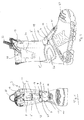
- eine Vorderansicht eines Stiefels mit zwei seitlichen Schaftabschnitten zeigt, wobei auf dem Vorderteil ein Protektor gemäß einer Ausführungsform der Erfindung angeordnet ist, der über eine flexible Verbindung mit einem Teilprotektor zum Schutz des Schienbeins verbunden ist;
- Fig. 2
- eine seitliche Ansicht des Stiefels mit dem Protektor gemäß der in
Fig. 1 gezeigten Ausführungsform zeigt; - Fig. 3
- eine seitliche Ansicht des Stiefels mit dem Protektor gemäß der in
Fig. 1 gezeigten Ausführungsform von der anderen Seite zeigt; - Fig. 4a,b
- den Protektor gemäß der erfindungsgemäßen Ausführungsform in einer perspektivischen Ansicht von oben (
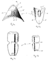
Fig. 4a ) und von unten (Fig. 4b ) zeigen; - Fig. 5a,b
- den Teilprotektor für das Schienbein gemäß der erfindungsgemäßen Ausführungsform in einer perspektivischen Ansicht von oben (
Fig. 5a ) und von unten (Fig. 5b ) zeigen; und - Fig. 6
- schematisch die Schnürung des in den
Fig. 1 gezeigten Schuhs gemäß einer Ausführungsform zeigt.bis 3
- Fig. 1
- a front view of a boot with two lateral shank portions, wherein on the front part of a protector according to an embodiment of the invention is arranged, which is connected via a flexible connection with a partial protector for the protection of the tibia;
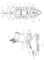
- Fig. 2
- a side view of the boot with the protector according to the in
Fig. 1 shown embodiment; - Fig. 3
- a side view of the boot with the protector according to the in
Fig. 1 shown embodiment from the other side; - Fig. 4a, b
- the protector according to the embodiment of the invention in a perspective view from above (
Fig. 4a ) and from below (Fig. 4b ) demonstrate; - Fig. 5a, b
- the partial protector for the tibia according to the embodiment of the invention in a perspective view from above (
Fig. 5a ) and from below (Fig. 5b ) demonstrate; and - Fig. 6
- schematically the lacing of the
Fig. 1 to 3 shown shoe according to one embodiment.
Die Erfindung wird beispielhaft anhand eines Ausführungsbeispiels des erfindungsgemäßen Protektors 1 an einem Stiefel 3 für Feuerwehr- und Katastropheneinsätze beschrieben, wie er in
Der Stiefel 3 umfasst einen Schaft mit zwei seitlichen Schaftabschnitten 5, 5', die bei der gezeigten Ausführungsform mit zwei. Die erste Schnürung umfasst ein Schnürband 7, dessen Enden jeweils durch Befestigungspunkte 9, 9' an den Schaftabschnitten 5, 5' geführt sind und diese vor einer Lasche 11 des Stiefels 3 miteinander verbinden. Wie in
Der erfindungsgemäße Protektor 1 auf dem Vorderteil des Schuhs 3 ist als eine längliche herzförmige Kappe ausgebildet, deren Breite sich zum unteren, zur Schuhspitze gerichteten Ende verringert. Der Protektor 1 ist so geformt, dass er im wesentlichen lediglich an seinen Rändern 14, 14' auf dem Vorderteil des Schuhs 3 aufliegt, während im Bereich zwischen den Rändern 14, 14' ein Abstand zur Oberseite des Schuhs 3 verbleibt. An der Unterseite des Protektors 1 ist somit ein Hohlraum gebildet, der eine Dämpfung von Stößen bewirkt. Um einen wirkungsvollen Schutz gegen Stöße und andere Außeneinwirkungen zu bieten, weist der aus einem schwer entflammbaren Material gebildete Protektor 1 darüber hinaus eine hohe Biegesteifigkeit auf.The
Zusätzlich ist im Protektor 1 in Richtung seiner Längsachse eine grabenförmige Vertiefung 15 ausgebildet. Deren Tiefe ist so gewählt, dass der auf der Vorderseite des Schuhs aufliegende Protektor 1 bei einer nicht übermäßig gestrafften Schnürung am seinem tiefsten Punkt der Vertiefung 15 noch nicht mit dem Schuh 3 in Berührung kommt, um optimale Dämpfungs- und Stoßfangeigenschaften des Protektors 1 zu erzielen. Jedoch ist dies nicht zwingend erforderlich und die Vertiefung 15 könnte auch so gewählt werden, dass sie die Oberfläche des Schuhs 3 berührt. Darüber hinaus könnten statt einer Vertiefung 15 mehrere, wie beispielsweise zwei, drei, vier oder fünf nebeneinander angeordnete Vertiefungen vorgesehen sein. Im Falle mehrer nebeneinander angeordneter Vertiefungen könnten ihre Längsrichtungen zueinander einen Winkel von beispielsweise 5° oder 10° zueinander aufweisen. Auch könnten die Vertiefungen in der Längsrichtung gekrümmt sein,In addition, a trench-shaped
Am Boden der Vertiefung 15 sind im vorderen zum Schaft gerichteten Teil derselben an den beiden gegenüberliegenden Wänden zwei längliche Öffnungen 16, 16' ausgebildet. In der Nähe des hinteren zur Schuhspitze orientierten Endes der Vertiefung 15 sind im Boden an den beiden gegenüberliegenden Wänden zwei runde Öffnungen 17, 17' ausgebildet.At the bottom of the
Der Protektor 1 wird im wesentlichen an vier auf dem Vorderteil des Schuhs 3 angeordneten und durch Schlaufen gebildeten Befestigungspunkte 9 gehalten. Wie insbesondere in
Der erfindungsgemäße Protektor 1 besitzt aufgrund seiner Form, der speziellen Anordnung, Befestigung und Führung des Schnürbandes 7 durch die Öffnungen 16, 16', 17,17' am Protektor 1 die Eigenschaft, dass er beim Straffen des Schnürbandes 7 automatisch auf der Vorderseite des Schuhs an der gewünschten Stelle angeordnet und dort zentriert wird. Durch das Schnürband 7 wird der Protektor 1 an die Vorderseite des Schuhs 3 gezogen.The
In den
Wie insbesondere in
Die Enden beider Schnürbänder 7 und 8 können jeweils an einem Griffteil 29 befestigt sein. In den Figuren ist jedoch ein gemeinsames Griffteil 29 gezeigt, an dem beide Schnürbänder 7 und 8 befestigt sind und das in einer oben am Schaft vorgesehenen Tasche 31 aufbewahrt werden kann. Zum Festziehen und Zentrieren des Protektors 1 auf dem Vorderteil des Schuhs werden die Enden des ersten Schnürbandes 7 an der Oberseite des Schaftes ergriffen und gezogen, so dass die Schnürung gestrafft wird. Die Schließvorrichtung 13 verhindert dabei ein Lockern oder Lösen der Schnürung. In derselben Weise wird gleichzeitig auch das zweite Schnürband 8 gestrafft.The ends of both
Oben an der Lasche 11 des Schuhs ist eine Schlaufe 33 angebracht, die das Öffnen des Schuhs 3 erleichtert. Durch Ziehen an der Schlaufe 33 werden bei geöffneter Schließvorrichtung 13 beide Schürungen gelockert und kann der Schaft erweitert werden, so dass der Schuh 3 mit geringem Kraftaufwand vom Fuß ausgezogen werden kann.At the top of the
Ferner umfasst der Schuh 3 einen Knöchelprotektor 26, 26' auf jeder Seite des Schuhs 3 sowie eine Stahlkappe 27 an der SpitzeFurther, the
Bei dem gezeigten Ausführungsbeispiel handelt es sich bei dem Schuh 3 um einen Stiefel für Feuerwehr- und Katastropheneinsätze, der aus Leder gefertigt ist. Teile des Schuhs 3 können auch aus anderen Materialien hergestellt sein, wie beispielsweise Kunststoff, Metall usw. Für die Verwendung an einem solchen Stiefel 3 bestehen der Protektor 1 und der Teilprotektor 19 aus einem feuer-, stoß- und/oder bruchfestem Material. Zahlreiche Modifizierungen können an dem erfindungsgemäßen Protektor 1 und dem Teilprotektor 19 vorgenommen werden, ohne den Umfang der Erfindung zu verlassen. Der Protektor 1 und der Teilprotektor 19 könnten weitere Lagen aus einem oder mehreren Materialien aufweisen, die für einen Einsatzzweck gewünschte Materialeigenschaften aufweist, wie beispielsweise besondere thermische Eigenschaften.In the illustrated embodiment, the
Der Protektor 1 könnte darüber hinaus aus einer dickeren Materialschicht ausgebildet sein und unmittelbar auf dem Vorderteil des Schuhs 3 aufliegen. Die Materialschicht könnte mit Hohlräumen versehen sein, die dem Protektor 1 Dämpfungseigenschaften verleihen. Der Teilprotektor 19 könnte in ähnlicher Weise aufgebaut sein.The
Es wäre darüber hinaus denkbar, den Protektor 1 mit mehreren hintereinander angeordneten Teilprotektoren aufzubauen. Die Teilprotektoren könnten an ihren Verbindungsstellen beweglich verbunden sein, um sich so der Form des Schafts anzupassen.It would also be conceivable to construct the
Bei der gezeigten Ausführungsform wird der Protektor 1 von einem Schnürband 7 und der Teilprotektor 19 durch ein zusätzliches Schnürband 8 gehalten. Es wäre jedoch auch denkbar nur ein einziges Schnürband zur Befestigung des Protektors 1 und des Teilprotektors 19 sowie zur Schnürung des gesamten Stiefels 3 zu verwenden. Darüber hinaus könnte der Verlauf der Schnürung anders gewählt werden, als hier beispielhaft gezeigt ist.In the embodiment shown, the
Die Merkmale der in den Ansprüchen offenbarten Erfindung können für die Realisierung der Erfindung entweder alleine oder in jeder beliebigen Kombination von Bedeutung sein.The features of the invention disclosed in the claims may be relevant to the practice of the invention either alone or in any combination.
- 11
- Protektorprotector
- 33
- Schuhshoe
- 5, 5'5, 5 '
- Schaftabschnitteshank portions
- 77
- Erstes SchnürbandFirst lace
- 88th
- Zweites SchnürbandSecond lace
- 9, 9'9, 9 '
- BesfestigungspunkteBesfestigungspunkte
- 1111
- Lascheflap
- 1313
- Schließvorrichtungclosing device
- 14, 14'14, 14 '
- Rändermargins
- 1515
- Vertiefungdeepening
- 16, 16'16, 16 '
- längliche Öffnungenelongated openings
- 17, 17'17, 17 '
- runde Öffnungenround openings
- 1818
- Deckelcover
- 1919
- Teilprotektorpart protector
- 2121
- Materialverbindungmaterial connection
- 2323
- Rillegroove
- 2525
- Rillegroove
- 26,26
- 26'Knöchelprotektor26'Knöchelprotektor
- 2727
- Stahlkappesteel cap
- 2929
- Griffteilhandle part
- 3131
- Taschebag
- 3333
- Schlaufeloop
Claims (17)
Priority Applications (3)
| Application Number | Priority Date | Filing Date | Title |
|---|---|---|---|
| ES10155484T ES2698440T3 (en) | 2010-03-04 | 2010-03-04 | Protector for shoes |
| EP10155484.8A EP2363033B1 (en) | 2010-03-04 | 2010-03-04 | Protector for shoes |
| PCT/EP2011/053299 WO2011107588A1 (en) | 2010-03-04 | 2011-03-04 | Protector for shoes |
Applications Claiming Priority (1)
| Application Number | Priority Date | Filing Date | Title |
|---|---|---|---|
| EP10155484.8A EP2363033B1 (en) | 2010-03-04 | 2010-03-04 | Protector for shoes |
Publications (2)
| Publication Number | Publication Date |
|---|---|
| EP2363033A1 true EP2363033A1 (en) | 2011-09-07 |
| EP2363033B1 EP2363033B1 (en) | 2018-08-22 |
Family
ID=42750104
Family Applications (1)
| Application Number | Title | Priority Date | Filing Date |
|---|---|---|---|
| EP10155484.8A Active EP2363033B1 (en) | 2010-03-04 | 2010-03-04 | Protector for shoes |
Country Status (3)
| Country | Link |
|---|---|
| EP (1) | EP2363033B1 (en) |
| ES (1) | ES2698440T3 (en) |
| WO (1) | WO2011107588A1 (en) |
Cited By (1)
| Publication number | Priority date | Publication date | Assignee | Title |
|---|---|---|---|---|
| AT16420U1 (en) * | 2018-06-29 | 2019-08-15 | Oeproma Projektrealisationen Gmbh | metal protectors |
Citations (4)
| Publication number | Priority date | Publication date | Assignee | Title |
|---|---|---|---|---|
| WO2000064292A1 (en) * | 1999-04-27 | 2000-11-02 | Normac Agencies Pty Ltd | Protector for footwear |
| WO2001035784A1 (en) * | 1999-11-15 | 2001-05-25 | Shepherd Stephen H | Padded shoe |
| US20050257404A1 (en) * | 2004-05-24 | 2005-11-24 | Daza James A | Protective covering for footwear |
| WO2007053886A1 (en) * | 2005-11-09 | 2007-05-18 | Downunder Distribution Group Pty Limited | Foot guard |
Family Cites Families (1)
| Publication number | Priority date | Publication date | Assignee | Title |
|---|---|---|---|---|
| US7941943B2 (en) * | 2007-10-22 | 2011-05-17 | Nike, Inc. | Ball control insert |
-
2010
- 2010-03-04 ES ES10155484T patent/ES2698440T3/en active Active
- 2010-03-04 EP EP10155484.8A patent/EP2363033B1/en active Active
-
2011
- 2011-03-04 WO PCT/EP2011/053299 patent/WO2011107588A1/en active Application Filing
Patent Citations (4)
| Publication number | Priority date | Publication date | Assignee | Title |
|---|---|---|---|---|
| WO2000064292A1 (en) * | 1999-04-27 | 2000-11-02 | Normac Agencies Pty Ltd | Protector for footwear |
| WO2001035784A1 (en) * | 1999-11-15 | 2001-05-25 | Shepherd Stephen H | Padded shoe |
| US20050257404A1 (en) * | 2004-05-24 | 2005-11-24 | Daza James A | Protective covering for footwear |
| WO2007053886A1 (en) * | 2005-11-09 | 2007-05-18 | Downunder Distribution Group Pty Limited | Foot guard |
Cited By (1)
| Publication number | Priority date | Publication date | Assignee | Title |
|---|---|---|---|---|
| AT16420U1 (en) * | 2018-06-29 | 2019-08-15 | Oeproma Projektrealisationen Gmbh | metal protectors |
Also Published As
| Publication number | Publication date |
|---|---|
| ES2698440T3 (en) | 2019-02-04 |
| EP2363033B1 (en) | 2018-08-22 |
| WO2011107588A1 (en) | 2011-09-09 |
Similar Documents
| Publication | Publication Date | Title |
|---|---|---|
| EP3027075B1 (en) | Shoe, particularly a sports shoe | |
| DE60009019T2 (en) | High shaft shoe with lace closure | |
| EP0919261B1 (en) | Protective padding for foot and tibia of a person, especially for sportsmen | |
| AT396542B (en) | SPORTSHOE, ESPECIALLY CROSS-COUNTRY SKI SHOE | |
| EP0702521A1 (en) | Shoe with a central rotary fastener | |
| EP3657939B1 (en) | Device for protecting paws | |
| DE3811105A1 (en) | SHOE, ESPECIALLY SPORTSHOE | |
| EP2908677B1 (en) | Dynamic shin guard | |
| AT517092B1 (en) | ski boot | |
| DE4023659A1 (en) | CROSS-COUNTRY SKI BOOT | |
| AT403757B (en) | OPTIMIZED UPPER DESIGN FOR TALL SHOES AND BOOTS | |
| AT517582B1 (en) | ski boot | |
| EP2363033B1 (en) | Protector for shoes | |
| EP2383024A2 (en) | Ski shoe, ski and ski binding | |
| DE10314741B4 (en) | snowboard binding | |
| EP2587952B1 (en) | Tongue for a shoe, and shoe | |
| EP2446765A1 (en) | Safety shoes with protective cap | |
| DE102013006969B4 (en) | Closure system for shoes and boots, especially safety shoes | |
| EP2522240B1 (en) | Shoe with heel instep pull system | |
| EP3863917B1 (en) | Binding | |
| AT13427U1 (en) | metatarsal protector | |
| WO2021105394A1 (en) | Shoe having a safety function | |
| DE202007003730U1 (en) | Safety boot in particular to be worn by fireman, comprises zip fastener with overlapping non inflammable cover segments | |
| DE102012004631A1 (en) | Protective sandal e.g. gymnastic sandal for e.g. gymnastic, has plastic material that is provided with holding lug and/or retaining strap, and curved sole that is embedded in plastic material | |
| DE892567C (en) | Protective cap for shoes, especially work shoes |
Legal Events
| Date | Code | Title | Description |
|---|---|---|---|
| PUAI | Public reference made under article 153(3) epc to a published international application that has entered the european phase |
Free format text: ORIGINAL CODE: 0009012 |
|
| AK | Designated contracting states |
Kind code of ref document: A1 Designated state(s): AT BE BG CH CY CZ DE DK EE ES FI FR GB GR HR HU IE IS IT LI LT LU LV MC MK MT NL NO PL PT RO SE SI SK SM TR |
|
| AX | Request for extension of the european patent |
Extension state: AL BA ME RS |
|
| 17P | Request for examination filed |
Effective date: 20120307 |
|
| 17Q | First examination report despatched |
Effective date: 20150702 |
|
| STAA | Information on the status of an ep patent application or granted ep patent |
Free format text: STATUS: EXAMINATION IS IN PROGRESS |
|
| GRAP | Despatch of communication of intention to grant a patent |
Free format text: ORIGINAL CODE: EPIDOSNIGR1 |
|
| STAA | Information on the status of an ep patent application or granted ep patent |
Free format text: STATUS: GRANT OF PATENT IS INTENDED |
|
| INTG | Intention to grant announced |
Effective date: 20180308 |
|
| RIN1 | Information on inventor provided before grant (corrected) |
Inventor name: HAIMERL, EWALD |
|
| RAP1 | Party data changed (applicant data changed or rights of an application transferred) |
Owner name: HERO GMBH & CO. KG |
|
| RIN1 | Information on inventor provided before grant (corrected) |
Inventor name: HAIMERL, EWALD |
|
| GRAS | Grant fee paid |
Free format text: ORIGINAL CODE: EPIDOSNIGR3 |
|
| GRAA | (expected) grant |
Free format text: ORIGINAL CODE: 0009210 |
|
| STAA | Information on the status of an ep patent application or granted ep patent |
Free format text: STATUS: THE PATENT HAS BEEN GRANTED |
|
| AK | Designated contracting states |
Kind code of ref document: B1 Designated state(s): AT BE BG CH CY CZ DE DK EE ES FI FR GB GR HR HU IE IS IT LI LT LU LV MC MK MT NL NO PL PT RO SE SI SK SM TR |
|
| REG | Reference to a national code |
Ref country code: GB Ref legal event code: FG4D Free format text: NOT ENGLISH |
|
| REG | Reference to a national code |
Ref country code: CH Ref legal event code: EP |
|
| REG | Reference to a national code |
Ref country code: AT Ref legal event code: REF Ref document number: 1031436 Country of ref document: AT Kind code of ref document: T Effective date: 20180915 |
|
| REG | Reference to a national code |
Ref country code: IE Ref legal event code: FG4D Free format text: LANGUAGE OF EP DOCUMENT: GERMAN |
|
| REG | Reference to a national code |
Ref country code: DE Ref legal event code: R096 Ref document number: 502010015279 Country of ref document: DE |
|
| REG | Reference to a national code |
Ref country code: CH Ref legal event code: NV Representative=s name: E. BLUM AND CO. AG PATENT- UND MARKENANWAELTE , CH |
|
| REG | Reference to a national code |
Ref country code: NL Ref legal event code: MP Effective date: 20180822 |
|
| REG | Reference to a national code |
Ref country code: LT Ref legal event code: MG4D |
|
| PG25 | Lapsed in a contracting state [announced via postgrant information from national office to epo] |
Ref country code: NO Free format text: LAPSE BECAUSE OF FAILURE TO SUBMIT A TRANSLATION OF THE DESCRIPTION OR TO PAY THE FEE WITHIN THE PRESCRIBED TIME-LIMIT Effective date: 20181122 Ref country code: SE Free format text: LAPSE BECAUSE OF FAILURE TO SUBMIT A TRANSLATION OF THE DESCRIPTION OR TO PAY THE FEE WITHIN THE PRESCRIBED TIME-LIMIT Effective date: 20180822 Ref country code: IS Free format text: LAPSE BECAUSE OF FAILURE TO SUBMIT A TRANSLATION OF THE DESCRIPTION OR TO PAY THE FEE WITHIN THE PRESCRIBED TIME-LIMIT Effective date: 20181222 Ref country code: GR Free format text: LAPSE BECAUSE OF FAILURE TO SUBMIT A TRANSLATION OF THE DESCRIPTION OR TO PAY THE FEE WITHIN THE PRESCRIBED TIME-LIMIT Effective date: 20181123 Ref country code: FI Free format text: LAPSE BECAUSE OF FAILURE TO SUBMIT A TRANSLATION OF THE DESCRIPTION OR TO PAY THE FEE WITHIN THE PRESCRIBED TIME-LIMIT Effective date: 20180822 Ref country code: NL Free format text: LAPSE BECAUSE OF FAILURE TO SUBMIT A TRANSLATION OF THE DESCRIPTION OR TO PAY THE FEE WITHIN THE PRESCRIBED TIME-LIMIT Effective date: 20180822 Ref country code: BG Free format text: LAPSE BECAUSE OF FAILURE TO SUBMIT A TRANSLATION OF THE DESCRIPTION OR TO PAY THE FEE WITHIN THE PRESCRIBED TIME-LIMIT Effective date: 20181122 Ref country code: LT Free format text: LAPSE BECAUSE OF FAILURE TO SUBMIT A TRANSLATION OF THE DESCRIPTION OR TO PAY THE FEE WITHIN THE PRESCRIBED TIME-LIMIT Effective date: 20180822 |
|
| REG | Reference to a national code |
Ref country code: ES Ref legal event code: FG2A Ref document number: 2698440 Country of ref document: ES Kind code of ref document: T3 Effective date: 20190204 |
|
| PG25 | Lapsed in a contracting state [announced via postgrant information from national office to epo] |
Ref country code: HR Free format text: LAPSE BECAUSE OF FAILURE TO SUBMIT A TRANSLATION OF THE DESCRIPTION OR TO PAY THE FEE WITHIN THE PRESCRIBED TIME-LIMIT Effective date: 20180822 Ref country code: LV Free format text: LAPSE BECAUSE OF FAILURE TO SUBMIT A TRANSLATION OF THE DESCRIPTION OR TO PAY THE FEE WITHIN THE PRESCRIBED TIME-LIMIT Effective date: 20180822 |
|
| PG25 | Lapsed in a contracting state [announced via postgrant information from national office to epo] |
Ref country code: PL Free format text: LAPSE BECAUSE OF FAILURE TO SUBMIT A TRANSLATION OF THE DESCRIPTION OR TO PAY THE FEE WITHIN THE PRESCRIBED TIME-LIMIT Effective date: 20180822 Ref country code: EE Free format text: LAPSE BECAUSE OF FAILURE TO SUBMIT A TRANSLATION OF THE DESCRIPTION OR TO PAY THE FEE WITHIN THE PRESCRIBED TIME-LIMIT Effective date: 20180822 Ref country code: RO Free format text: LAPSE BECAUSE OF FAILURE TO SUBMIT A TRANSLATION OF THE DESCRIPTION OR TO PAY THE FEE WITHIN THE PRESCRIBED TIME-LIMIT Effective date: 20180822 Ref country code: CZ Free format text: LAPSE BECAUSE OF FAILURE TO SUBMIT A TRANSLATION OF THE DESCRIPTION OR TO PAY THE FEE WITHIN THE PRESCRIBED TIME-LIMIT Effective date: 20180822 Ref country code: IT Free format text: LAPSE BECAUSE OF FAILURE TO SUBMIT A TRANSLATION OF THE DESCRIPTION OR TO PAY THE FEE WITHIN THE PRESCRIBED TIME-LIMIT Effective date: 20180822 |
|
| REG | Reference to a national code |
Ref country code: DE Ref legal event code: R097 Ref document number: 502010015279 Country of ref document: DE |
|
| PG25 | Lapsed in a contracting state [announced via postgrant information from national office to epo] |
Ref country code: SK Free format text: LAPSE BECAUSE OF FAILURE TO SUBMIT A TRANSLATION OF THE DESCRIPTION OR TO PAY THE FEE WITHIN THE PRESCRIBED TIME-LIMIT Effective date: 20180822 Ref country code: SM Free format text: LAPSE BECAUSE OF FAILURE TO SUBMIT A TRANSLATION OF THE DESCRIPTION OR TO PAY THE FEE WITHIN THE PRESCRIBED TIME-LIMIT Effective date: 20180822 Ref country code: DK Free format text: LAPSE BECAUSE OF FAILURE TO SUBMIT A TRANSLATION OF THE DESCRIPTION OR TO PAY THE FEE WITHIN THE PRESCRIBED TIME-LIMIT Effective date: 20180822 |
|
| PLBE | No opposition filed within time limit |
Free format text: ORIGINAL CODE: 0009261 |
|
| STAA | Information on the status of an ep patent application or granted ep patent |
Free format text: STATUS: NO OPPOSITION FILED WITHIN TIME LIMIT |
|
| 26N | No opposition filed |
Effective date: 20190523 |
|
| PG25 | Lapsed in a contracting state [announced via postgrant information from national office to epo] |
Ref country code: SI Free format text: LAPSE BECAUSE OF FAILURE TO SUBMIT A TRANSLATION OF THE DESCRIPTION OR TO PAY THE FEE WITHIN THE PRESCRIBED TIME-LIMIT Effective date: 20180822 |
|
| PG25 | Lapsed in a contracting state [announced via postgrant information from national office to epo] |
Ref country code: MC Free format text: LAPSE BECAUSE OF FAILURE TO SUBMIT A TRANSLATION OF THE DESCRIPTION OR TO PAY THE FEE WITHIN THE PRESCRIBED TIME-LIMIT Effective date: 20180822 |
|
| GBPC | Gb: european patent ceased through non-payment of renewal fee |
Effective date: 20190304 |
|
| PG25 | Lapsed in a contracting state [announced via postgrant information from national office to epo] |
Ref country code: IE Free format text: LAPSE BECAUSE OF NON-PAYMENT OF DUE FEES Effective date: 20190304 Ref country code: GB Free format text: LAPSE BECAUSE OF NON-PAYMENT OF DUE FEES Effective date: 20190304 |
|
| PG25 | Lapsed in a contracting state [announced via postgrant information from national office to epo] |
Ref country code: TR Free format text: LAPSE BECAUSE OF FAILURE TO SUBMIT A TRANSLATION OF THE DESCRIPTION OR TO PAY THE FEE WITHIN THE PRESCRIBED TIME-LIMIT Effective date: 20180822 |
|
| PG25 | Lapsed in a contracting state [announced via postgrant information from national office to epo] |
Ref country code: PT Free format text: LAPSE BECAUSE OF FAILURE TO SUBMIT A TRANSLATION OF THE DESCRIPTION OR TO PAY THE FEE WITHIN THE PRESCRIBED TIME-LIMIT Effective date: 20181222 Ref country code: MT Free format text: LAPSE BECAUSE OF FAILURE TO SUBMIT A TRANSLATION OF THE DESCRIPTION OR TO PAY THE FEE WITHIN THE PRESCRIBED TIME-LIMIT Effective date: 20180822 |
|
| PG25 | Lapsed in a contracting state [announced via postgrant information from national office to epo] |
Ref country code: CY Free format text: LAPSE BECAUSE OF FAILURE TO SUBMIT A TRANSLATION OF THE DESCRIPTION OR TO PAY THE FEE WITHIN THE PRESCRIBED TIME-LIMIT Effective date: 20180822 |
|
| PG25 | Lapsed in a contracting state [announced via postgrant information from national office to epo] |
Ref country code: HU Free format text: LAPSE BECAUSE OF FAILURE TO SUBMIT A TRANSLATION OF THE DESCRIPTION OR TO PAY THE FEE WITHIN THE PRESCRIBED TIME-LIMIT; INVALID AB INITIO Effective date: 20100304 |
|
| PG25 | Lapsed in a contracting state [announced via postgrant information from national office to epo] |
Ref country code: MK Free format text: LAPSE BECAUSE OF FAILURE TO SUBMIT A TRANSLATION OF THE DESCRIPTION OR TO PAY THE FEE WITHIN THE PRESCRIBED TIME-LIMIT Effective date: 20180822 |
|
| PGFP | Annual fee paid to national office [announced via postgrant information from national office to epo] |
Ref country code: LU Payment date: 20230227 Year of fee payment: 14 Ref country code: FR Payment date: 20230123 Year of fee payment: 14 Ref country code: AT Payment date: 20230227 Year of fee payment: 14 |
|
| PGFP | Annual fee paid to national office [announced via postgrant information from national office to epo] |
Ref country code: BE Payment date: 20230216 Year of fee payment: 14 |
|
| P01 | Opt-out of the competence of the unified patent court (upc) registered |
Effective date: 20230510 |
|
| PGFP | Annual fee paid to national office [announced via postgrant information from national office to epo] |
Ref country code: ES Payment date: 20230406 Year of fee payment: 14 Ref country code: DE Payment date: 20230331 Year of fee payment: 14 Ref country code: CH Payment date: 20230401 Year of fee payment: 14 |