EP2362243A1 - Optoelectronic sensor - Google Patents
Optoelectronic sensor Download PDFInfo
- Publication number
- EP2362243A1 EP2362243A1 EP10154692A EP10154692A EP2362243A1 EP 2362243 A1 EP2362243 A1 EP 2362243A1 EP 10154692 A EP10154692 A EP 10154692A EP 10154692 A EP10154692 A EP 10154692A EP 2362243 A1 EP2362243 A1 EP 2362243A1
- Authority
- EP
- European Patent Office
- Prior art keywords
- light
- sensor
- intensity
- received signal
- evaluation unit
- Prior art date
- Legal status (The legal status is an assumption and is not a legal conclusion. Google has not performed a legal analysis and makes no representation as to the accuracy of the status listed.)
- Granted
Links
Images


Classifications
-
- G—PHYSICS
- G01—MEASURING; TESTING
- G01V—GEOPHYSICS; GRAVITATIONAL MEASUREMENTS; DETECTING MASSES OR OBJECTS; TAGS
- G01V8/00—Prospecting or detecting by optical means
- G01V8/10—Detecting, e.g. by using light barriers
- G01V8/20—Detecting, e.g. by using light barriers using multiple transmitters or receivers
-
- Y—GENERAL TAGGING OF NEW TECHNOLOGICAL DEVELOPMENTS; GENERAL TAGGING OF CROSS-SECTIONAL TECHNOLOGIES SPANNING OVER SEVERAL SECTIONS OF THE IPC; TECHNICAL SUBJECTS COVERED BY FORMER USPC CROSS-REFERENCE ART COLLECTIONS [XRACs] AND DIGESTS
- Y10—TECHNICAL SUBJECTS COVERED BY FORMER USPC
- Y10T—TECHNICAL SUBJECTS COVERED BY FORMER US CLASSIFICATION
- Y10T29/00—Metal working
- Y10T29/49—Method of mechanical manufacture
- Y10T29/49002—Electrical device making
Definitions
- the invention relates to an optoelectronic sensor according to the preamble of claim 1 and to a method for producing and mounting such a sensor according to the preamble of claim 11.
- Photocells operate on the principle of emitting a light beam, registering in a light receiver and evaluating whether the received signal exceeds a switching threshold or not.
- Photoelectric sensors are known which have a transmitter and an opposite receiver as one-way light barriers, between which the surveillance area is spanned, or which, as reflection light barriers, align the transmitter and receiver with a reflector, so that a double light path is created.
- a light grid effectively several of these einstrahligen sensors are joined together in parallel, in which case, of course, parts of the switching electronics of several beams can be shared.
- FIG. 5 A known cause of faulty circuits is the so-called reflection, the basis of the FIG. 5 is explained using the example of a light grid 100 shown only partially with a transmitter bar 102 and a receiver bar 104.
- the direct light beam 106 in the receiver strip 104 is registered in each case.
- a specular object 108 opens in FIG. 5a an additional, indirect light path for a UmLiteungslichtstrahl 110. If now the protective field is violated, as in FIG. 5b If an object 112 interrupts the direct transmitted light beam 106, this is not detected in the receiver strip 104, because the reversal light beam 110 is still detected there.
- the beam angle of the light emitter and the receiving angle of the light receiver is limited to an acceptance angle, depending on the standard requirements up to only ⁇ 2.5 °.
- FIG. 5c explains the mirroring situation with these acceptance angles.
- the specular object 108 lies outside a light-emitting cone 114 defined by the acceptance angle and is not illuminated at all.
- reflected light would not be detected by the object 108, since it is irradiated from outside a receiving light cone 116 likewise defined by the acceptance angle.
- the indirect light path 110 therefore can not arise, and the interruption of the direct light path 106 is detected by the sensor 100. Reflections are only conceivable in the very small space region in which transmit light cone 114 and received light cone 116 intersect. As an additional organizational measure, the standards require that there should be no reflecting surfaces close to the protective field and, in particular, within this small space area.
- the light transmitter and the light receiver must be aligned very precisely and thus consuming.
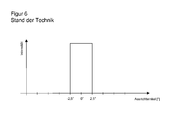
- optics with very sharp and precisely defined diaphragms are used. This leads to a FIG. 6 shown very narrow and steep intensity curve as a function of the alignment angle, in which the light emitter and light receiver to each other.
- the light signal at azimuth angles beyond the acceptance angle is zero, has very steep, nearly vertical edges at the critical angle of ⁇ 2.5 °, and is often saturated by factors on the order of 1000 times within the acceptance angle range.
- a data light barrier with two sensor units wherein the second sensor unit of the first sensor unit notifies a measured reception intensity.
- the first sensor unit indicates this as a measure of the quality of the alignment.
- this measure is only a relative measure, which is still very much of the according to DE 101 06 755 A1 unknown distance depends.
- it can be determined by pivoting with the conventional system, in which direction the adjustment is improved and deteriorated.
- it still has to be adjusted until the desired alignment is achieved, and there is no quantitative indication of the error angles.
- no requirements for Umspiegelungs none, since it ultimately does not matter if the optical transmission path is direct or indirect, and thus no acceptance angle is given.
- the invention is based on the basic idea of using instead of saturated signals those signals whose intensity profile shows a detectable dependence on the alignment angle. Then it is concluded from a measured reception intensity on the current alignment angle. The acceptance angle is now not enforced by adjustment, but set electronically by two thresholds to the measured reception intensity. If the current alignment angle does not yet fall within a range in which an intensity band is electronically adjustable due to very gross misalignment, the user can be given information as to how much the alignment still deviates from ideal alignment.
- the invention has the advantage that light is received over a much larger Ausrichtwinkel Anlagen and thereby the sensor can be mounted in accordance with tolerant Ausrichtwinkeln. A more precise alignment is not required, because the desired according to the protection class of standards acceptance angle for Umadorungsdeem be met by electronic adjustment.
- the transmission optics and / or receiving optics are much simpler, since exact apertures for setting a narrow, steep intensity profile as in FIG. 6 are dispensable.
- the Light output for the light emitters does not have to be increased, since according to the invention additionally utilized light energy is conventionally also present in larger orientation angles, but is covered by the diaphragms.
- the light transmitters are operated in smaller than the maximum possible ranges with smaller transmission currents. This also reduces infrared radiation into the environment and the influence of other systems. Conversely, the light receivers are not saturated and thus able to detect interference radiation from the outside.
- the inventively provided upper and lower threshold define an intensity band around the measured reception intensity.
- an angle band called the acceptance angle range is first placed around the current alignment angle, which fulfills the predetermined requirement of, for example, ⁇ 2.5 °.
- the intensity curve then converts between the intensity and the alignment angle.
- the sensor is aware of the complete functional relationship between alignment angle and intensity over the practically relevant angle range and with the practically relevant resolution.
- the intensity profile is preferably stored as a value table, which contains as many values as are required for the requirements on the acceptance angle.
- a calculation rule is stored which generates the function of the intensity profile. This calculation rule can also be used, for example, as the basis for the transmission current, provided that the relationship between the transmission current and the optical output power is sufficiently reliable.
- the evaluation unit is preferably designed to detect a beam interruption at an intensity of the received signal below the lower threshold and a reversal or extraneous light at an intensity of the received signal above the upper threshold.
- a light beam is considered to be uninterrupted as long as the intensity of the received signal is within the intensity band between the lower and upper threshold.
- An outbreak from the intensity band is detected and a certain minimum time may be required to distinguish events to be detected from temporary disturbances by dust or the like.
- the reception intensity drops during an object intervention by at least partial shading of the light beam, which is recognized by the lower threshold. But too much light means a mistake, because the actual light beam in its reception intensity does not increase without reason.
- Possible causes are extraneous light, which can be faded out by encoding the transmission beam, and above all a reflection, since their light from comes from the associated transmitter and therefore is also coded correctly. If the upper threshold is exceeded, no object intervention has yet taken place, but the sensor reports an error so that the reflection or other source of interference is removed.
- an intensity profile is preferably stored for different distances between the light emitter and the light receiver.
- the evaluation unit is designed to convert the intensity profile for different distances.
- an intensity profile is given at a fixed distance and transformed on the basis of the quadratic distance law.
- the distance is divided into discrete classes between minimum and maximum range of the sensor and stored for each distance class, an intensity curve, which is then interpolated on the basis of the law of distance.
- the sensor preferably has an input device for configuring the distance between the light transmitter and the light receiver. Since the absolute values of the intensity profile are evaluated and this depends strongly on the distance, the distance is parameterized to the sensor in this way.
- the evaluation unit is adapted to measure the distance between the light emitter and the light receiver. This can be done for example by a light transit time method. In a light grid there is another, in the EP 1 544 643 A1 presented option is to count the number of receivable by a light receiver light emitter, which increases with the distance.
- the sensor is specified for a fixed distance and set up.
- the acceptance angle range is configurable. Conventionally, for a different acceptance angle, for example a change from ⁇ 2.5 ° to ⁇ 5 °, the transmitting and / or receiving optics must be replaced. According to the invention, an electronic adjustment that exploits the dependence of the acceptance angle range on the distance between the lower threshold and the upper threshold is sufficient.
- the sensor preferably has a display which contains information about how much the alignment angle deviates from an ideal alignment.
- the measured during the adjustment received intensity the sensor with the aid of the intensity curve can be converted directly into an alignment angle, which is also the deviation from the ideal orientation at 0 °, in which the intensity maximum centered on the light receiver.
- the sensor outputs this numerical value in degrees an LCD display, as a color or number of an LED or the like.
- the continuous increase and decrease of the intensity curve thus makes it possible to realize a continuous electronic alignment display. With the help of this continuous display, the fitter can also quickly find the direction in which the alignment is further improved.
- alignment is not mandatory: gross misalignments in which no signal is received despite the extended angular range are visible to the naked eye, and as soon as a signal is received, the two thresholds can be set electronically without further alignment. Improved alignment, however, increases the functional reserves.
- the light transmitter and / or the light receiver preferably has a transmitting optics or a receiving optics, which ensures that the intensity of the received signal drops evenly with the alignment angle.
- a well evaluable intensity profile is achieved.
- the intensity profile is saturated for no alignment angles, whereby saturation in a small interval around 0 ° is conceivable and harmless.
- the intensity profile drops around the optimal alignment at an alignment angle of 0 ° in both directions, ie with the amount of the alignment angle, monotonically or even strictly monotonically. Evaluable intensities over larger angles are achieved than typical safety angles.
- the intensity profile thus drops only at, for example, ⁇ 5 ° or even only at ⁇ 7.5 ° or more, at ⁇ 10 ° or more, or at ⁇ 15 ° or more to a small, no longer reliably measurable value.
- the intensity profile depends uniquely on the sign, apart from a sign, from the alignment angle. Since small angle errors have no practical effect, no strict monotony needs to be demanded as long as constant portions are small. Because of the axial symmetry to the ideal alignment angle this uniqueness is given only to a sign.
- the intensity profile allows the unambiguous inference of a measured intensity on the amount of the alignment angle. Examples of an intensity course that satisfies these conditions are a Gauss curve, a parabola, a triangle, and similar functions. The most robust is a linear intensity curve, ie a triangular shape, where appropriate, a kind of dent in the top is to be provided, since an installer will try to align with the tip and this is virtually impossible with a real triangle. Alternatively, it is also conceivable to completely omit the transmitting optics and the natural beam profile of the light source or from their internal optics. This also produces a Gaussian and in any case a monotonically decreasing intensity profile on both sides.
- the evaluation unit is preferably designed to check the optical output power of the light transmitter.
- the transmission currents can first be checked.
- conventional light sources often do not reliably produce a desired optical output power for a given transmit current, but are specified only for a minimum output that can be doubled or more. Therefore, it is even more preferable to provide a receiver adjacent to the light emitter to measure the actual light output.
- a receiver adjacent to the light emitter In a light grid in which light emitters and light receivers are mixed in a bar, one of the already present adjacent light receivers can take over this task with an optical bypass. Another possibility is that the opposite receiver of the other bar measures the light output and returns this information optically coded to the first bar as in a data light barrier.
- the light output can then also be readjusted to restore the originally stored output power and thus compensate, for example, a creeping pollution.
- the alignment must be maintained, otherwise the sensor can not differentiate between alignment errors and optical output losses.
- the sensor is preferably formed as a light grid with a plurality of optoelectronic sensors with only one light beam, wherein the individual light beams are arranged parallel to each other.
- the individual light rays are also called channels.
- a light grid it is not necessary for all the components to be multiplied, but, for example, the housing, connections and evaluation unit can be shared.
- the intensity curves are, if the internal offset of the light beams remains small, equal to each other and do not necessarily have to be stored multiple times.
- a switch-off signal can be output via a safe output of the light grid if one of the received signals falls below the lower threshold or exceeds the upper threshold.
- the sensor is then a safe light grid, which acts as a non-contact protective device in safety applications is used, which spans a protective field to secure a source of danger.
- the shutdown signal silences the safety-related machine that forms the source of danger.
- the evaluation unit is preferably designed to obtain information about the orientation of the light emitter relative to the light receivers from a comparison of the intensities of a plurality of light beams.
- the maximum of the intensity distribution of all channels is located centrally on the light receiver.
- the evaluation unit calculates information in which axis the alignment is not correct, that is, whether a bar is rotated about its major axis, tilted forward or tilted sideways, and also to what extent the angle is incorrect. Due to the axial symmetry of the intensity distribution, the sign of the alignment angle can only be specified from several measurements assuming the continuity of the alignment movement. Alternatively, it is conceivable to use asymmetrical intensity distributions in a targeted manner, for example by an asymmetrical aperture, and in this way also to determine the sign.
- the plausibility of the measured intensities is checked in operation after completion of the assembly and thus with fixed alignment.
- the orientation and thus the individual expected intensities in the channels are then known, and a correlation can detect significant differences in order to improve the reliability of the individual evaluations.
- the optical output powers of the light emitters are preferably measured, and transmission currents for the light emitters are set to correspond to a desired output power.
- tolerances of the light transmitters are compensated, the specification of which often does not guarantee that the same optical output power is delivered with the same transmission current.
- the output power is known, because otherwise the assignment of alignment angle to intensity at a given distance and accordingly the threshold setting for the acceptance angle range is not correct. Since conventionally in the final production, the exit angle and the minimum intensities are checked, it means only very small and fully automatable additional effort to use the already existing measurement results for the intensity also to adjust the transmission currents.
- deviations from the parallel alignment of the light transmitters with respect to one another are measured and stored.
- the aim is that the optical axes of the light emitter are completely parallel to each other.
- the remaining tolerances can be stored by learning the actual intensity curve in the final production and compensated later during operation. For example, it is assumed that the intensity profile itself is identical in all channels and only stores an offset in the alignment angle. Alternatively, all intensity profiles are taught and thus also form different beam characteristics of the light emitter.
- FIG. 1 shows a schematic cross-sectional view of a light barrier 10.
- a transmitting part 12 includes a light emitter 14, for example an LED or a laser in the infrared or another spectrum.
- the light of the light transmitter 14 is collimated with a downstream transmitting optics 16 and sent as a light beam 18 through a monitoring area 20 to a receiving part 22.
- the light beam 18 impinges via a receiving optical system 24 on a light receiver 26, which is usually designed as a photodiode, but alternatively can also be a spatially resolving CCD or CMOS image sensor.
- the transmitting optics 16 and the receiving optics 24 can comprise further elements such as additional lenses, diaphragms and the like and ensure that the light beam 18 has a desired beam profile and consequently a predefined intensity profile as a function of an alignment angle in the transmitting part 12 and receiving part 22 are aligned with each other.
- the intensity profile without special optics is already achieved by the natural radiation or the internal structure of the light transmitter 14.
- An evaluation unit 28 is connected to the light receiver 26 and thus receives an electrical reception signal which corresponds to the intensity of the received light. With the aid of two thresholds which are derived from an intensity profile stored in a memory 28a, the evaluation unit 28 checks whether the reception intensity of the light beam 18 remains within an intensity band. If this is not the case, then the light beam 18 is interrupted or there is a reversal or interference by extraneous light. A corresponding signal is output via an output 30 of the sensor 10.
- FIG. 2 shows as a further embodiment of an optoelectronic invention, a schematic cross-sectional view of a light grid 10.
- the transmitting part 12 is formed as a transmitter strip with a plurality of arranged in a row of light emitters 14, which in each case a light receiver 26 is assigned in a trained as a receiver strip receiving part. Notwithstanding the illustration, light transmitter 14 and light receiver 26 may also be mixedly distributed on the two strips 12, 22.
- the light grid 10 is formed according to the standards mentioned above. If the evaluation unit 28 detects an intervention in the protective field 20 spanned by the light beams 18, because at least one light beam 18 is interrupted and therefore the reception intensity in the associated light receiver 26 falls below a lower threshold, then a safety-related shutdown command is transmitted via the safe output 30 (OSSD). Output Signal Switching Device). A shutdown command also occurs when the evaluation unit 28 detects an error. A particular error is the presence of a reflection which is detected by an upper threshold being exceeded.
- FIG. 3 shows an exemplary intensity curve as a function of the alignment angle.
- the transmitting part 12 and the receiving part 22 are ideally aligned with one another when the intensity maximum lies at 0 ° in the center of the light receiver 26.
- the shown intensity profile including absolute amplitude values only applies for a specific distance between transmitter part 12 and receiver part 22 and is known to evaluation unit 28. For this, the distance is first measured or entered. The evaluation unit 28 then calculates the intensity profile for the actual distance or can access the memory 28a in which the intensity profile belonging to the distance is stored.
- the transmitting part 12 and the receiving part 22 are aligned only roughly with respect to each other. Then the reception intensity 32 is measured and converted into an alignment angle with the aid of the intensity profile.
- the evaluation unit 28 places an acceptance angle range 34 around this alignment angle which, for example, corresponds to a maximum possible angular range required by the standard.
- the acceptance angle range 34 assigns the evaluation unit 28 an intensity band 36 with a lower threshold 38 and an upper threshold 40 on the basis of the intensity profile.
- the evaluation unit 28 has no way to determine from a single measurement whether it is on the rising or falling edge of the intensity profile. But this makes no practical difference, since the same thresholds 38, 40 would be set on the falling edge.
- the intensity profile should be monotonic on both sides, even linear if possible, so that the threshold distance becomes independent of the orientation.
- Flat sections in the intensity curve lead too close adjacent or even coincident thresholds 38, 40 and should therefore extend at least only over fractions of the required acceptance angle range 34.
- the evaluation unit 28 monitors whether the received signal remains between the lower threshold 38 and the upper threshold 40.
- a drop below the lower threshold 38 is interpreted as an interruption of the light beam 18 and thus as object detection.
- Exceeding the upper threshold 40 is interpreted as a mirroring. Both lead to a corresponding signal at the output 30, in the case of a safety application also to a safety-related shutdown command.
- the thresholds In order for the thresholds to be fail-safe during operation, it is necessary to regularly test whether the intensity profile stored in the evaluation unit 28 still corresponds to the actual reception intensity with undisturbed light beam 18. For this purpose, the optical output power of the light emitter 14 must be monitored.
- a display of the sensor 10 is provided in a further embodiment, which continuously indicates the current alignment angle, which was derived from the reception intensity 32. This allows the alignment to be improved quickly and purposefully. The process can be aborted at any time, and the evaluation unit 28 determines the two thresholds 38, 40 with the achieved alignment as described above.
- FIG. 4 shows several intensity courses to several channels of a light grid 10 as a function of the acceptance angle.
- the evaluation unit 28 can derive by comparison a statement about the position of transmitter strip 12 and receiver strip 22 relative to one another and indicate in which axis of rotation which alignment angles relative to ideal alignment is present. This information is again unsigned because of the symmetrical intensity curves, so it can not indicate a direction based on a measurement. Through continuous evaluation or display but can also determine the direction.
- a certain proportion of the offset of the intensity curves in FIG. 4 may be due not to the alignment but to manufacturing tolerances of the parallel alignment of the light rays 18. Therefore, it is provided in a continuation of the invention to train in the final inspection of the production of the light grid 10, as the intensity distribution is at each light transmitter 14 and light receiver 26 to a common axis. The offset of each light beam 18 thus determined can then be compensated for during operation, so that the position and rotation of the light grid 18 can be inferred from the correlation of the measured values of the various optical channels instead of manufacturing tolerances.
Abstract
Description
Die Erfindung betrifft einen optoelektronischen Sensor nach dem Oberbegriff von Anspruch 1 sowie ein Verfahren zur Herstellung und Montage eines derartigen Sensors nach dem Oberbegriff von Anspruch 11.The invention relates to an optoelectronic sensor according to the preamble of claim 1 and to a method for producing and mounting such a sensor according to the preamble of claim 11.
Lichtschranken arbeiten nach dem Prinzip, einen Lichtstrahl auszusenden, in einem Lichtempfänger zu registrieren und zu bewerten, ob das Empfangssignal eine Schaltschwelle überschreitet oder nicht. Bekannt sind Lichtschranken, die als Einweglichtschranken einen Sender und einen gegenüberliegenden Empfänger aufweisen, zwischen denen der Überwachungsbereich aufgespannt ist, oder die als Reflexionslichtschranken den Sender und Empfänger auf einen Reflektor ausrichten, so dass ein doppelter Lichtweg entsteht. Bei einem Lichtgitter werden effektiv mehrere dieser einstrahligen Sensoren parallel zueinander zusammengefügt, wobei dann natürlich Teile der Schaltelektronik von mehreren Strahlen gemeinsam genutzt werden können.Photocells operate on the principle of emitting a light beam, registering in a light receiver and evaluating whether the received signal exceeds a switching threshold or not. Photoelectric sensors are known which have a transmitter and an opposite receiver as one-way light barriers, between which the surveillance area is spanned, or which, as reflection light barriers, align the transmitter and receiver with a reflector, so that a double light path is created. In a light grid effectively several of these einstrahligen sensors are joined together in parallel, in which case, of course, parts of the switching electronics of several beams can be shared.
Ein wichtiges Anwendungsgebiet derartiger optoelektronischer Sensoren ist die Sicherheitstechnik. Dabei wird der Zugang zu einer Gefahrenquelle, beispielsweise eine gefährliche Maschine, von dem Sensor überwacht, der bei unzulässigem Eingriff in das von den Strahlen aufgespannte Schutzfeld einen Abschaltbefehl erzeugt oder die Gefahr auf andere Weise abwendet, etwa durch Verbringen in eine sichere Parkposition. Da von der Funktionsfähigkeit des Sensors Gesundheit und Leben von Personen abhängt, sind die Anforderungen für in der Sicherheitstechnik eingesetzte Sensoren sehr streng und normiert, beispielsweise in der EN13849 für Maschinensicherheit oder der Gerätenorm EN61496 für berührungslos wirkende Schutzeinrichtungen.An important field of application of such optoelectronic sensors is safety technology. In this case, the access to a source of danger, such as a dangerous machine, is monitored by the sensor, which generates a shutdown command in impermissible intervention in the protective field spanned by the beams or averts the danger in another way, such as by moving into a safe parking position. Since the functionality of the sensor depends on the health and life of persons, the requirements for sensors used in safety technology are very strict and standardized, for example in EN13849 for machine safety or the device standard EN61496 for non-contact protective devices.
Wegen dieser Sicherheitsanforderungen müssen Fehlschaltungen des Sensors vermieden werden. Eine bekannte Ursache von Fehlschaltungen ist die sogenannte Umspiegelung, die anhand der
Um Umspiegelungen zu verhindern, wird herkömmlich der Abstrahlwinkel der Lichtsender und der Empfangswinkel der Lichtempfänger auf einen Akzeptanzwinkel begrenzt, und zwar je nach Normanforderungen auf bis zu nur ±2,5°.
Durch die Winkelbegrenzung des Sendelichts und des Empfangslichts müssen Lichtsender und der Lichtempfänger sehr genau und damit aufwändig ausgerichtet werden. Um geringe Akzeptanzwinkel über den großen Dynamikbereich des Lichtsignals, der durch die quadratische Abhängigkeit zwischen Lichtintensität und Abstand zwischen Lichtsender und Lichtempfänger entsteht, zuverlässig einhalten zu können, werden Optiken mit sehr scharf und genau definierten Blenden verwendet. Dies führt zu einem in
Diese Charakteristik des Intensitätsverlaufs führt aber dazu, dass nicht nur sehr genau ausgerichtet werden muss. Zugleich ist eine elektronische Justierhilfe, die während des Ausrichtvorgangs das momentane Empfangssignal anzeigt, praktisch unbrauchbar, da eine solche Anzeige meist auf Null steht und bei Eintritt in den Akzeptanzwinkel unvermittelt in den Vollausschlag geht, ohne dabei einen Hinweis darauf zu geben, inwieweit der gewünschte Ausrichtwinkel mittig getroffen ist.However, this characteristic of the intensity curve means that not only must be aligned very precisely. At the same time, an electronic adjustment aid, which displays the current received signal during the alignment process, virtually unusable, since such a display is usually zero and when entering the acceptance angle is suddenly in the full scale, without giving any indication as to how much the desired alignment angle is hit in the middle.
Aus der
In der
In der
Es ist weiterhin im Stand der Technik bekannt, statt einer einfachen Schaltschwelle mehrere Schwellen zu verwenden. Damit soll die Dynamik der Empfangsintensität im laufenden Betrieb bei freiem Strahlengang kompensiert werden, die etwa durch Umgebungslicht, Verschmutzung oder unterschiedliche optische Eigenschaften zu detektierender Objekte entsteht. In der
Es ist daher Aufgabe der Erfindung, die Ausrichtung eines gattungsgemäßen Sensors zu vereinfachen. Dabei soll der Sensor umspiegelungssicher bleiben.It is therefore an object of the invention to simplify the alignment of a generic sensor. In this case, the sensor should remain umpolungssicher.
Diese Aufgabe wird durch einen optoelektronischen Sensor gemäß Anspruch 1 sowie ein Verfahren zur Herstellung und Montage eines Sensors gemäß Anspruch 11 gelöst. Dabei geht die Erfindung von dem Grundgedanken aus, statt mit gesättigten Signalen solche Signale zu verwenden, deren Intensitätsverlauf eine detektierbare Abhängigkeit von dem Ausrichtwinkel zeigt. Dann wird aus einer gemessenen Empfangsintensität auf den momentanen Ausrichtwinkel geschlossen. Der Akzeptanzwinkel wird nun nicht durch Justage erzwungen, sondern elektronisch durch zwei Schwellen um die gemessene Empfangsintensität eingestellt. Fällt der momentane Ausrichtwinkel wegen sehr grober Fehlausrichtung noch nicht in einen Bereich, in dem ein Intensitätsband elektronisch einstellbar ist, so kann dem Benutzer eine Information gegeben werden, um wieviel die Ausrichtung noch von idealer Ausrichtung abweicht.This object is achieved by an optoelectronic sensor according to claim 1 and a method for producing and assembling a sensor according to claim 11. The invention is based on the basic idea of using instead of saturated signals those signals whose intensity profile shows a detectable dependence on the alignment angle. Then it is concluded from a measured reception intensity on the current alignment angle. The acceptance angle is now not enforced by adjustment, but set electronically by two thresholds to the measured reception intensity. If the current alignment angle does not yet fall within a range in which an intensity band is electronically adjustable due to very gross misalignment, the user can be given information as to how much the alignment still deviates from ideal alignment.
Die Erfindung hat den Vorteil, dass Licht über einen deutlich größeren Ausrichtwinkelbereich empfangen wird und dadurch der Sensor in entsprechend toleranten Ausrichtwinkeln montiert werden kann. Eine genauere Ausrichtung ist nicht erforderlich, denn die je nach Schutzklasse der Normen gewünschten Akzeptanzwinkel für Umspiegelungssicherheit werden durch elektronische Einstellung eingehalten. Die Sendeoptiken und/oder Empfangsoptiken sind wesentlich einfacher, da exakte Blenden zur Einstellung eines schmalen, steilen Intensitätsverlaufs wie in
Die erfindungsgemäß vorgesehene obere und untere Schwelle legen ein Intensitätsband um die gemessene Empfangsintensität fest. Dazu wird zunächst um den momentanen Ausrichtwinkel ein als Akzeptanzwinkelbereich bezeichnetes Winkelband gelegt, welches die vorgegebene Anforderung von beispielsweise ±2,5° erfüllt. Über den Intensitätsverlauf erfolgt dann eine Umrechnung zwischen Intensität und Ausrichtwinkel. Dabei ist dem Sensor der vollständige funktionale Zusammenhang von Ausrichtwinkel und Intensität über den praktisch relevanten Winkelbereich und mit der praktisch relevanten Auflösung bekannt. Der Intensitätsverlauf ist bevorzugt als Wertetabelle gespeichert, welche so viele Werte enthält, wie für die Anforderungen an den Akzeptanzwinkel erforderlich sind. Alternativ wird eine Rechenvorschrift gespeichert, welche die Funktion des Intensitätsverlaufs erzeugt. Dieser Rechenvorschrift kann beispielsweise auch der Sendestrom zugrunde gelegt werden, sofern der Zusammenhang zwischen Sendestrom und optischer Ausgangsleistung hinreichend verlässlich ist.The inventively provided upper and lower threshold define an intensity band around the measured reception intensity. For this purpose, an angle band called the acceptance angle range is first placed around the current alignment angle, which fulfills the predetermined requirement of, for example, ± 2.5 °. The intensity curve then converts between the intensity and the alignment angle. The sensor is aware of the complete functional relationship between alignment angle and intensity over the practically relevant angle range and with the practically relevant resolution. The intensity profile is preferably stored as a value table, which contains as many values as are required for the requirements on the acceptance angle. Alternatively, a calculation rule is stored which generates the function of the intensity profile. This calculation rule can also be used, for example, as the basis for the transmission current, provided that the relationship between the transmission current and the optical output power is sufficiently reliable.
Die Auswertungseinheit ist bevorzugt dafür ausgebildet, eine Strahlunterbrechung an einer Intensität des Empfangssignals unterhalb der unteren Schwelle und eine Umspiegelung oder Fremdlicht an einer Intensität des Empfangssignals oberhalb der oberen Schwelle zu erkennen. Ein Lichtstrahl gilt als nicht unterbrochen, solange die Intensität des Empfangssignals innerhalb des Intensitätsbandes zwischen unterer und oberer Schwelle liegt. Ein Ausbruch aus dem Intensitätsband wird detektiert, wobei eine gewisse Mindestzeit gefordert werden kann, um zu detektierende Ereignisse von temporären Störungen durch Staub oder dergleichen zu unterscheiden. Die Empfangsintensität fällt bei einem Objekteingriff durch zumindest teilweise Abschattung des Lichtstrahls ab, was durch die untere Schwelle erkannt wird. Aber auch zuviel Licht bedeutet einen Fehler, da der eigentliche Lichtstrahl in seiner Empfangsintensität nicht grundlos zunimmt. Mögliche Ursachen sind Fremdlicht, das aber durch Codierung des Sendestrahls ausblendbar ist, und vor allem eine Umspiegelung, da deren Licht von dem zugeordneten Sender stammt und daher auch richtig codiert ist. Bei Überschreitung der oberen Schwelle ist noch kein Objekteingriff erfolgt, aber der Sensor meldet einen Fehler, damit die Umspiegelung oder sonstige Störquelle entfernt wird.The evaluation unit is preferably designed to detect a beam interruption at an intensity of the received signal below the lower threshold and a reversal or extraneous light at an intensity of the received signal above the upper threshold. A light beam is considered to be uninterrupted as long as the intensity of the received signal is within the intensity band between the lower and upper threshold. An outbreak from the intensity band is detected and a certain minimum time may be required to distinguish events to be detected from temporary disturbances by dust or the like. The reception intensity drops during an object intervention by at least partial shading of the light beam, which is recognized by the lower threshold. But too much light means a mistake, because the actual light beam in its reception intensity does not increase without reason. Possible causes are extraneous light, which can be faded out by encoding the transmission beam, and above all a reflection, since their light from comes from the associated transmitter and therefore is also coded correctly. If the upper threshold is exceeded, no object intervention has yet taken place, but the sensor reports an error so that the reflection or other source of interference is removed.
In dem Speicher ist bevorzugt für verschiedene Entfernungen zwischen dem Lichtsender und dem Lichtempfänger je ein Intensitätsverlauf abgelegt. Alternativ ist die Auswertungseinheit dafür ausgebildet, den Intensitätsverlauf für verschiedene Entfernungen umzurechnen. Dazu wird ein Intensitätsverlauf bei einer festen Entfernung vorgegeben und aufgrund des quadratischen Abstandsgesetzes transformiert. In einer Mischform wird die Entfernung in diskrete Klassen zwischen minimaler und maximaler Reichweite des Sensors unterteilt und zu jeder Entfernungsklasse ein Intensitätsverlauf gespeichert, der dann auf Basis des Abstandsgesetzes interpoliert wird.In the memory, an intensity profile is preferably stored for different distances between the light emitter and the light receiver. Alternatively, the evaluation unit is designed to convert the intensity profile for different distances. For this purpose, an intensity profile is given at a fixed distance and transformed on the basis of the quadratic distance law. In a mixed form, the distance is divided into discrete classes between minimum and maximum range of the sensor and stored for each distance class, an intensity curve, which is then interpolated on the basis of the law of distance.
Der Sensor weist bevorzugt eine Eingabeeinrichtung zur Konfiguration der Entfernung zwischen dem Lichtsender und dem Lichtempfänger auf. Da die Absolutwerte des Intensitätsverlaufes ausgewertet werden und dieser stark von der Entfernung abhängt, wird dem Sensor auf diese Weise die Entfernung parametriert. Alternativ ist die Auswertungseinheit dafür ausgebildet, die Entfernung zwischen dem Lichtsender und dem Lichtempfänger zu messen. Dies kann beispielsweise durch ein Lichtlaufzeitverfahren geschehen. In einem Lichtgitter besteht eine weitere, in der
Vorteilhafterweise ist der Akzeptanzwinkelbereich konfigurierbar. Herkömmlich muss für einen anderen Akzeptanzwinkel, beispielsweise einem Wechsel von ±2,5° auf ±5°, die Sende- und/oder Empfangsoptik ausgetauscht werden. Erfindungsgemäß genügt eine elektronische Einstellung, welche die Abhängigkeit des Akzeptanzwinkelbereichs von dem Abstand zwischen unterer Schwelle und oberer Schwelle ausnutzt.Advantageously, the acceptance angle range is configurable. Conventionally, for a different acceptance angle, for example a change from ± 2.5 ° to ± 5 °, the transmitting and / or receiving optics must be replaced. According to the invention, an electronic adjustment that exploits the dependence of the acceptance angle range on the distance between the lower threshold and the upper threshold is sufficient.
Der Sensor weist bevorzugt eine Anzeige auf, welche eine Information darüber enthält, um wieviel der Ausrichtwinkel von einer idealen Ausrichtung abweicht. Die während der Justierung gemessene Empfangsintensität kann der Sensor mit Hilfe des Intensitätsverlaufs unmittelbar in einen Ausrichtwinkel umrechnen, der zugleich die Abweichung von der idealen Ausrichtung bei 0° ist, bei der das Intensitätsmaximum mittig auf dem Lichtempfänger liegt. Diesen Zahlenwert in Grad gibt der Sensor beispielsweise auf einer LCD-Anzeige, als Farbe oder Anzahl einer LED oder dergleichen aus. Durch das stetige Ansteigen und Abfallen des Intensitätsverlaufs kann somit eine kontinuierliche elektronische Ausrichtanzeige realisiert werden. Mit Hilfe dieser kontinuierlichen Anzeige findet der Monteur auch sehr schnell die Richtung, in welche die Ausrichtung sich weiter verbessert. Eine Ausrichtung ist aber nicht zwingend: Grobe Fehlausrichtungen, in denen trotz des erweiterten Winkelbereichs gar kein Signal empfangen wird, sind mit bloßem Auge erkennbar, und sobald ein Signal empfangen wird, können die beiden Schwellen ohne weitere Ausrichtung elektronisch festgelegt werden. Eine verbesserte Ausrichtung erhöht aber die Funktionsreserven.The sensor preferably has a display which contains information about how much the alignment angle deviates from an ideal alignment. The measured during the adjustment received intensity, the sensor with the aid of the intensity curve can be converted directly into an alignment angle, which is also the deviation from the ideal orientation at 0 °, in which the intensity maximum centered on the light receiver. For example, the sensor outputs this numerical value in degrees an LCD display, as a color or number of an LED or the like. The continuous increase and decrease of the intensity curve thus makes it possible to realize a continuous electronic alignment display. With the help of this continuous display, the fitter can also quickly find the direction in which the alignment is further improved. However, alignment is not mandatory: gross misalignments in which no signal is received despite the extended angular range are visible to the naked eye, and as soon as a signal is received, the two thresholds can be set electronically without further alignment. Improved alignment, however, increases the functional reserves.
Der Lichtsender und/oder der Lichtempfänger weist bevorzugt eine Sendeoptik beziehungsweise eine Empfangsoptik auf, die dafür sorgt, dass die Intensität des Empfangssignals gleichmäßig mit dem Ausrichtwinkel abfällt. Somit wird also ein gut auswertbarer Intensitätsverlauf erreicht. Der Intensitätsverlauf ist insbesondere für keine Ausrichtwinkel gesättigt, wobei eine Sättigung in einem kleinen Intervall um 0° herum denkbar und unschädlich ist. Der Intensitätsverlauf fällt um die optimale Ausrichtung bei einem Ausrichtwinkel von 0° in beide Richtungen, also mit dem Betrag des Ausrichtwinkels, monoton oder sogar streng monoton ab. Dabei werden auswertbare Intensitäten über größere Winkel erreicht als typische sicherheitstechnische Winkel. Der Intensitätsverlauf fällt also erst bei beispielsweise ±5° oder sogar erst bei ±7.5° oder mehr, bei ±10° oder mehr oder bei ±15° oder mehr auf einen kleinen, nicht mehr zuverlässig messbaren Wert ab.The light transmitter and / or the light receiver preferably has a transmitting optics or a receiving optics, which ensures that the intensity of the received signal drops evenly with the alignment angle. Thus, therefore, a well evaluable intensity profile is achieved. In particular, the intensity profile is saturated for no alignment angles, whereby saturation in a small interval around 0 ° is conceivable and harmless. The intensity profile drops around the optimal alignment at an alignment angle of 0 ° in both directions, ie with the amount of the alignment angle, monotonically or even strictly monotonically. Evaluable intensities over larger angles are achieved than typical safety angles. The intensity profile thus drops only at, for example, ± 5 ° or even only at ± 7.5 ° or more, at ± 10 ° or more, or at ± 15 ° or more to a small, no longer reliably measurable value.
Bevorzugt hängt der Intensitätsverlauf bis auf ein Vorzeichen eineindeutig von dem Ausrichtwinkel ab. Da kleine Winkelfehler keine praktische Auswirkung haben, muss keine strenge Monotonie gefordert werden, solange konstante Teilbereiche klein sind. Wegen der Axialsymmetrie zu dem idealen Ausrichtwinkel ist diese Eineindeutigkeit nur bis auf ein Vorzeichen gegeben. Der Intensitätsverlauf erlaubt den eindeutigen Rückschluss von einer gemessenen Intensität auf den Betrag des Ausrichtwinkels. Beispiele für einen Intensitätsverlauf, der diese Bedingungen erfüllt, sind eine Gausskurve, eine Parabel, ein Dreieck und ähnliche Funktionen. Am robustesten ist ein linearer Intensitätsverlauf, also eine Dreiecksform, wobei gegebenenfalls eine Art Delle in der Spitze vorzusehen ist, da ein Monteur versuchen wird, auf die Spitze auszurichten und dies bei einem echten Dreieck praktisch nicht gelingt. Alternativ ist auch denkbar, die Sendeoptik ganz wegzulassen und das natürliche Strahlprofil der Lichtquelle oder von deren internen Optiken zu verwenden. Dabei entsteht ebenfalls ein in etwa gaussischer und jedenfalls ein zu beiden Seiten monoton abfallender Intensitätsverlauf.Preferably, the intensity profile depends uniquely on the sign, apart from a sign, from the alignment angle. Since small angle errors have no practical effect, no strict monotony needs to be demanded as long as constant portions are small. Because of the axial symmetry to the ideal alignment angle this uniqueness is given only to a sign. The intensity profile allows the unambiguous inference of a measured intensity on the amount of the alignment angle. Examples of an intensity course that satisfies these conditions are a Gauss curve, a parabola, a triangle, and similar functions. The most robust is a linear intensity curve, ie a triangular shape, where appropriate, a kind of dent in the top is to be provided, since an installer will try to align with the tip and this is virtually impossible with a real triangle. Alternatively, it is also conceivable to completely omit the transmitting optics and the natural beam profile of the light source or from their internal optics. This also produces a Gaussian and in any case a monotonically decreasing intensity profile on both sides.
Die Auswertungseinheit ist bevorzugt dafür ausgebildet, die optische Ausgangsleistung des Lichtsenders zu prüfen. Dazu können zunächst die Sendeströme geprüft werden. Herkömmliche Lichtquellen erzeugen aber oft bei gegebenem Sendestrom nicht zuverlässig eine gewünschte optische Ausgangsleistung, sondern sie sind lediglich für eine Mindestausgangsleistung spezifiziert, die um das Doppelte oder mehr übertroffen werden kann. Daher ist nochmals bevorzugt ein Empfänger neben dem Lichtsender vorgesehen, um die tatsächliche Lichtleistung zu messen. In einem Lichtgitter, in dem Lichtsender und Lichtempfänger in einer Leiste gemischt sind, kann einer der ohnehin vorhandenen benachbarten Lichtempfänger diese Aufgabe mit einem optischen Bypass übernehmen. Eine weitere Möglichkeit besteht darin, dass der gegenüberliegende Empfänger der anderen Leiste die Lichtleistung misst und diese Information wie bei einer Datenlichtschranke optisch codiert an die erste Leiste zurückgibt. Werden Abweichungen der optischen Ausgangsleistung gegenüber der ursprünglichen Lichtleistung festgestellt, so führt dies zu einem Fehler. In einem Wartungsmodus, in dem sichergestellt ist, dass die Lichtstrahlen frei sind, kann die Lichtleistung dann auch nachgeregelt werden, um die ursprünglich gespeicherte Ausgangsleistung wiederherzustellen und damit beispielsweise eine schleichende Verschmutzung auszugleichen. Dabei muss die Ausrichtung erhalten bleiben, da der Sensor sonst nicht zwischen Ausrichtfehlern und Verlusten der optischen Ausgangsleistung unterscheiden kann.The evaluation unit is preferably designed to check the optical output power of the light transmitter. For this purpose, the transmission currents can first be checked. However, conventional light sources often do not reliably produce a desired optical output power for a given transmit current, but are specified only for a minimum output that can be doubled or more. Therefore, it is even more preferable to provide a receiver adjacent to the light emitter to measure the actual light output. In a light grid in which light emitters and light receivers are mixed in a bar, one of the already present adjacent light receivers can take over this task with an optical bypass. Another possibility is that the opposite receiver of the other bar measures the light output and returns this information optically coded to the first bar as in a data light barrier. If deviations of the optical output power from the original light power are detected, this leads to an error. In a maintenance mode, in which it is ensured that the light beams are free, the light output can then also be readjusted to restore the originally stored output power and thus compensate, for example, a creeping pollution. The alignment must be maintained, otherwise the sensor can not differentiate between alignment errors and optical output losses.
Der Sensor ist bevorzugt als Lichtgitter mit einer Vielzahl von optoelektronischen Sensoren mit nur einem Lichtstrahl ausgebildet, wobei die einzelnen Lichtstrahlen parallel zueinander angeordnet sind. Die einzelnen Lichtstrahlen werden auch als Kanäle bezeichnet. Bei einem Lichtgitter müssen nicht notwendig sämtliche Komponenten vervielfacht werden, sondern beispielsweise Gehäuse, Anschlüsse und Auswertungseinheit können gemeinsam genutzt werden. Auch die Intensitätsverläufe sind, sofern der interne Versatz der Lichtstrahlen klein bleibt, untereinander gleich und müssen nicht unbedingt mehrfach gespeichert werden.The sensor is preferably formed as a light grid with a plurality of optoelectronic sensors with only one light beam, wherein the individual light beams are arranged parallel to each other. The individual light rays are also called channels. In the case of a light grid, it is not necessary for all the components to be multiplied, but, for example, the housing, connections and evaluation unit can be shared. The intensity curves are, if the internal offset of the light beams remains small, equal to each other and do not necessarily have to be stored multiple times.
Nochmals bevorzugt ist ein Abschaltsignal über einen sicheren Ausgang des Lichtgitters ausgebbar, wenn eines der Empfangssignale die untere Schwelle unterschreitet oder die obere Schwelle überschreitet. Der Sensor ist dann ein sicheres Lichtgitter, welches als berührungslos wirkende Schutzeinrichtung in sicherheitstechnischen Anwendungen eingesetzt wird, die ein Schutzfeld zur Absicherung einer Gefahrenquelle aufspannt. Das Abschaltsignal setzt die Maschine, welche die Gefahrenquelle bildet, sicherheitsgerichtet still.Again preferably, a switch-off signal can be output via a safe output of the light grid if one of the received signals falls below the lower threshold or exceeds the upper threshold. The sensor is then a safe light grid, which acts as a non-contact protective device in safety applications is used, which spans a protective field to secure a source of danger. The shutdown signal silences the safety-related machine that forms the source of danger.
Die Auswertungseinheit ist bevorzugt dafür ausgebildet, aus einem Vergleich der Intensitäten mehrerer Lichtstrahlen eine Information über die Ausrichtung der Lichtsender gegenüber den Lichtempfängern zu gewinnen. Bei optimal ausgerichtetem Lichtgitter liegt das Maximum der Intensitätsverteilung aller Kanäle mittig auf dem Lichtempfänger. Durch Korrelation der einzelnen Kanäle berechnet die Auswertungseinheit eine Information, in welcher Achse die Ausrichtung nicht stimmt, also ob eine Leiste um ihre Hauptachse verdreht, nach vorne verkippt oder seitlich verkippt ist, und auch in welchem Ausmaß der Winkel nicht stimmt. Das Vorzeichen des Ausrichtwinkels lässt sich wegen der Axialsymmetrie der Intensitätsverteilung nur aus mehreren Messungen unter Annahmen an die Stetigkeit der Ausrichtbewegung angeben. Alternativ ist denkbar, gezielt asymmetrische Intensitätsverteilungen zu verwenden, beispielsweise durch eine asymmetrische Blende, und auf diese Weise auch das Vorzeichen zu bestimmen.The evaluation unit is preferably designed to obtain information about the orientation of the light emitter relative to the light receivers from a comparison of the intensities of a plurality of light beams. When the light grid is optimally aligned, the maximum of the intensity distribution of all channels is located centrally on the light receiver. By correlating the individual channels, the evaluation unit calculates information in which axis the alignment is not correct, that is, whether a bar is rotated about its major axis, tilted forward or tilted sideways, and also to what extent the angle is incorrect. Due to the axial symmetry of the intensity distribution, the sign of the alignment angle can only be specified from several measurements assuming the continuity of the alignment movement. Alternatively, it is conceivable to use asymmetrical intensity distributions in a targeted manner, for example by an asymmetrical aperture, and in this way also to determine the sign.
Nach einem ganz ähnlichen Verfahren wird im Betrieb nach Abschluss der Montage und damit bei fester Ausrichtung die Plausibilität der gemessenen Intensitäten geprüft. Die Ausrichtung und damit die einzelnen zu erwartenden Intensitäten in den Kanälen sind dann bekannt, und eine Korrelation kann signifikante Unterschiede feststellen, um die Verlässlichkeit der Einzelauswertungen zu verbessern.After a very similar procedure, the plausibility of the measured intensities is checked in operation after completion of the assembly and thus with fixed alignment. The orientation and thus the individual expected intensities in the channels are then known, and a correlation can detect significant differences in order to improve the reliability of the individual evaluations.
Das erfindungsgemäße Verfahren kann auf ähnliche Weise weitergebildet werden und zeigt dabei ähnliche Vorteile. Derartige vorteilhafte Merkmale sind beispielhaft, aber nicht abschließend in den sich an die unabhängigen Ansprüche anschließenden Unteransprüchen beschrieben.The method according to the invention can be developed in a similar manner and shows similar advantages. Such advantageous features are described by way of example but not exhaustively in the subclaims following the independent claims.
Insbesondere werden bevorzugt die optischen Ausgangsleistungen der Lichtsender gemessen, und Sendeströme für die Lichtsender werden so eingestellt, dass sie einer gewünschten Ausgangsleistung entsprechen. Damit werden beispielsweise in der Endprüfung Toleranzen der Lichtsender ausgeglichen, deren Spezifizierung oft nicht garantiert, dass bei gleichem Sendestrom auch die gleiche optische Ausgangsleistung geliefert wird. Es ist für die Erfindung wichtig, dass die Ausgangsleistung bekannt ist, weil sonst die Zuordnung von Ausrichtwinkel zu Intensität bei gegebener Entfernung und entsprechend die Schwellensetzung für den Akzeptanzwinkelbereich nicht stimmt. Da schon herkömmlich in der Endfertigung die Austrittswinkel und die Mindestintensitäten überprüft werden, bedeutet es nur sehr geringen und völlig automatisierbaren Zusatzaufwand, die ohnehin vorhandenen Messergebnisse für die Intensität auch dafür zu nutzen, die Sendeströme einzustellen.In particular, the optical output powers of the light emitters are preferably measured, and transmission currents for the light emitters are set to correspond to a desired output power. Thus, for example, in the final test, tolerances of the light transmitters are compensated, the specification of which often does not guarantee that the same optical output power is delivered with the same transmission current. It is important for the invention that the output power is known, because otherwise the assignment of alignment angle to intensity at a given distance and accordingly the threshold setting for the acceptance angle range is not correct. Since conventionally in the final production, the exit angle and the minimum intensities are checked, it means only very small and fully automatable additional effort to use the already existing measurement results for the intensity also to adjust the transmission currents.
In einer bevorzugten Weiterbildung werden Abweichungen von der parallelen Ausrichtung der Lichtsender zueinander gemessen und gespeichert. Angestrebt ist, dass die optischen Achsen der Lichtsender völlig parallel zueinander sind. Die verbleibenden Toleranzen können durch Einlernen des tatsächlichen Intensitätsverlaufes in der Endfertigung abgespeichert und später im Betrieb kompensiert werden. Dabei geht man beispielsweise davon aus, dass der Intensitätsverlauf an sich in allen Kanälen identisch ist und speichert nur einen Versatz in dem Ausrichtwinkel. Alternativ werden alle Intensitätsverläufe eingelernt und bilden so auch unterschiedliche Strahlcharakteristika der Lichtsender ab.In a preferred refinement, deviations from the parallel alignment of the light transmitters with respect to one another are measured and stored. The aim is that the optical axes of the light emitter are completely parallel to each other. The remaining tolerances can be stored by learning the actual intensity curve in the final production and compensated later during operation. For example, it is assumed that the intensity profile itself is identical in all channels and only stores an offset in the alignment angle. Alternatively, all intensity profiles are taught and thus also form different beam characteristics of the light emitter.
Die Erfindung wird nachstehend auch hinsichtlich weiterer Merkmale und Vorteile beispielhaft anhand von Ausführungsformen und unter Bezug auf die beigefügte Zeichnung näher erläutert. Die Abbildungen der Zeichnung zeigen in:
- Fig. 1
- eine schematische Querschnittsdarstellung einer Lichtschranke;
- Fig. 2
- eine schematische Querschnittsdarstellung eines Lichtgitters;
- Fig. 3
- eine Darstellung des Intensitätsverlaufs in Abhängigkeit des Ausrichtwinkels zur Erläuterung der erfindungsgemäßen Schwellenbestimmung;
- Fig.4
- eine Darstellung mehrerer Intensitätsverläufe in Abhängigkeit des Ausrichtwinkels in verschiedenen Kanälen eines Lichtgitters;
- Fig. 5a-c
- Ausschnitte einer vereinfachten Querschnittsdarstellung eines Lichtgitters zur Erläuterung von Umspiegelung und Akzeptanzwinkel; und
- Fig. 6
- eine Darstellung des Intensitätsverlaufs in Abhängigkeit des Ausrichtwinkels nach dem Stand der Technik.
- Fig. 1
- a schematic cross-sectional view of a light barrier;
- Fig. 2
- a schematic cross-sectional view of a light grid;
- Fig. 3
- a representation of the intensity profile as a function of the alignment angle for explaining the threshold determination according to the invention;
- Figure 4
- a representation of multiple intensity gradients as a function of the alignment angle in different channels of a light grid;
- Fig. 5a-c
- Excerpts of a simplified cross-sectional representation of a light grid to explain Umspiegelung and acceptance angle; and
- Fig. 6
- a representation of the intensity profile as a function of the alignment angle according to the prior art.
Anhand der
Die Sendeoptik 16 sowie die Empfangsoptik 24 können entgegen der Darstellung weitere Elemente wie zusätzliche Linsen, Blenden und dergleichen umfassen und sorgen dafür, dass der Lichtstrahl 18 ein gewünschtes Strahlprofil und folglich einen vorgegebenen Intensitätsverlauf in Abhängigkeit von einem Ausrichtwinkel aufweist, in dem Sendeteil 12 und Empfangsteil 22 zueinander ausgerichtet sind. In einer alternativen Ausführungsform wird der Intensitätsverlauf ohne spezielle Optik bereits durch die natürliche Abstrahlung oder den internen Aufbau des Lichtsenders 14 erreicht.Contrary to the illustration, the transmitting
Eine Auswertungseinheit 28 ist mit dem Lichtempfänger 26 verbunden und erhält so ein elektrisches Empfangssignal, das der Intensität des Empfangslichts entspricht. Mit Hilfe von zwei Schwellen, die aus einem Intensitätsverlauf abgeleitet werden, der in einem Speicher 28a abgelegt ist, prüft die Auswertungseinheit 28, ob die Empfangsintensität des Lichtstrahls 18 innerhalb eines Intensitätsbandes bleibt. Ist das nicht der Fall, so ist der Lichtstrahl 18 unterbrochen beziehungsweise es liegt eine Umspiegelung oder Störung durch Fremdlicht vor. Ein entsprechendes Signal wird über einen Ausgang 30 des Sensors 10 ausgegeben.An
Für sicherheitstechnische Anwendungen ist das Lichtgitter 10 entsprechend der eingangs genannten Normen ausgebildet. Erkennt die Auswertungseinheit 28 einen Eingriff in das durch die Lichtstrahlen 18 aufgespannte Schutzfeld 20, weil mindestens ein Lichtstrahl 18 unterbrochen ist und deshalb die Empfangsintensität in dem zugehörigen Lichtempfänger 26 eine untere Schwelle unterschreitet, so wird ein sicherheitsgerichteter Abschaltbefehl über den sicheren Ausgang 30 (OSSD, Output Signal Switching Device) ausgegeben. Ein Abschaltbefehl erfolgt auch dann, wenn die Auswertungseinheit 28 einen Fehler erkennt. Ein besonderer Fehler ist das Vorliegen einer Umspiegelung, die an einem Überschreiten einer oberen Schwelle erkannt wird.For safety applications, the
Während der Montage des Sensor 10 werden Sendeteil 12 und Empfangsteil 22 nur grob nach Augenmaß zueinander ausgerichtet. Dann wird die Empfangsintensität 32 gemessen und mit Hilfe des Intensitätsverlaufs in einen Ausrichtwinkel umgerechnet. Um diesen Ausrichtwinkel legt die Auswertungseinheit 28 einen Akzeptanzwinkelbereich 34, der beispielsweise einem von der Norm geforderten höchstmöglichen Winkelbereich entspricht. Dem Akzeptanzwinkelbereich 34 wiederum ordnet die Auswertungseinheit 28 anhand des Intensitätsverlaufs ein Intensitätsband 36 mit einer unteren Schwelle 38 und einer oberen Schwelle 40 zu. Die Auswertungseinheit 28 hat aus einer einzelnen Messung keine Möglichkeit festzustellen, ob sie sich auf der steigenden oder fallenden Flanke des Intensitätsverlaufs befindet. Das macht aber keinen praktischen Unterschied, da auf der fallenden Flanke dieselben Schwellen 38, 40 festgelegt würden.During assembly of the
Der Intensitätsverlauf sollte wie einleitend beschrieben zu beiden Seiten monoton, nach Möglichkeit sogar linear abfallen, damit der Schwellenabstand unabhängig von der Ausrichtung wird. Flache Teilbereiche in dem Intensitätsverlauf führen zu nahe beieinander liegenden oder sogar zusammenfallenden Schwellen 38, 40 und sollten sich daher zumindest nur über Bruchteile des geforderten Akzeptanzwinkelbereichs 34 erstrecken.As described in the introduction, the intensity profile should be monotonic on both sides, even linear if possible, so that the threshold distance becomes independent of the orientation. Flat sections in the intensity curve lead too close adjacent or even
Im Betrieb überwacht die Auswertungseinheit 28, ob das Empfangssignal zwischen der unteren Schwelle 38 und der oberen Schwelle 40 bleibt. Ein Absinken unter die untere Schwelle 38 wird als Unterbrechung des Lichtstrahls 18 und damit als Objektfeststellung gewertet. Ein Überschreiten der oberen Schwelle 40 wird als Umspiegelung interpretiert. Beides führt zu einem entsprechenden Signal an dem Ausgang 30, im Falle einer sicherheitstechnischen Anwendung auch zu einem sicherheitsgerichteten Abschaltbefehl.In operation, the
Damit die Schwellen im Betrieb fehlersicher sind, muss regelmäßig getestet werden, ob der in der Auswertungseinheit 28 hinterlegte Intensitätsverlauf noch der tatsächlichen Empfangsintensität bei ungestörtem Lichtstrahl 18 entspricht. Dazu muss die optische Ausgangsleistung der Lichtsender 14 überwacht werden.In order for the thresholds to be fail-safe during operation, it is necessary to regularly test whether the intensity profile stored in the
Es ist erfindungsgemäß nicht zwingend notwendig, die erste grobe Ausrichtung weiter zu verbessern, weil die elektronische Einstellung der Schwellen 38, 40 die Einhaltung des Akzeptanzwinkels sicherstellt. Für eine größere Funktionsreserve ist es aber dennoch vorteilhaft, dem Idealfall eines Ausrichtwinkels von 0° zumindest näher zu kommen. Dazu ist in einer weiteren Ausführungsform eine Anzeige des Sensors 10 vorgesehen, welche kontinuierlich den momentanen Ausrichtwinkel anzeigt, der aus der Empfangsintensität 32 abgeleitet wurde. Damit lässt sich die Ausrichtung rasch und zielgerichtet verbessern. Der Vorgang kann jederzeit abgebrochen werden, und die Auswertungseinheit 28 legt mit der erreichten Ausrichtung die beiden Schwellen 38, 40 wie oben beschrieben fest.It is according to the invention not necessarily necessary to further improve the first coarse alignment, because the electronic adjustment of the
Ein gewisser Anteil am Versatz der Intensitätsverläufe in
Claims (15)
dadurch gekennzeichnet,
dass in einem Speicher (28a) des Sensors (10) der Intensitätsverlauf abgelegt ist und dass die Auswertungseinheit (28) dafür ausgebildet ist, anhand einer gemessenen Intensität des Empfangssignals aus dem Intensitätsverlauf eine untere Schwelle (38) und eine obere Schwelle (40) festzulegen, deren Abstand einem Akzeptanzwinkelbereich entspricht.Optoelectronic sensor (10), in particular light barrier, with a light transmitter (14) for emitting a light beam (18) and a light receiver (26) opposite the light transmitter (14) in an alignment angle for converting the received light beam (18) into an electrical reception signal, wherein the transmission power of the light emitter (14) and / or the receiving sensitivity of the light receiver (26) is set so that the received signal has a varying intensity with the alignment angle, and wherein an evaluation unit (28) of the sensor (10) is designed for, based the receiving signal to determine whether the light beam (18) is interrupted or not,
characterized,
in that the intensity profile is stored in a memory (28a) of the sensor (10) and that the evaluation unit (28) is designed to define a lower threshold (38) and an upper threshold (40) from the intensity profile based on a measured intensity of the received signal whose distance corresponds to an acceptance angle range.
wobei die Auswertungseinheit (28) dafür ausgebildet ist, eine Strahlunterbrechung an einer Intensität des Empfangssignals unterhalb der unteren Schwelle (38) und eine Umspiegelung oder Fremdlicht an einer Intensität des Empfangssignals oberhalb der oberen Schwelle (40) zu erkennen.Sensor (10) according to claim 1,
wherein the evaluation unit (28) is adapted to detect a beam interruption at an intensity of the received signal below the lower threshold (38) and a Umspiegelung or extraneous light at an intensity of the received signal above the upper threshold (40).
wobei in dem Speicher (28a) für verschiedene Entfernungen zwischen dem Lichtsender (14) und dem Lichtempfänger (26) je ein Intensitätsverlauf abgelegt ist, oder wobei die Auswertungseinheit (28) dafür ausgebildet ist, den Intensitätsverlauf für verschiedene Entfernungen umzurechnen.Sensor according to (10) claim 1 or 2,
wherein in the memory (28a) is deposited for different distances between the light transmitter (14) and the light receiver (26) each have an intensity profile, or wherein the evaluation unit (28) is adapted to convert the intensity profile for different distances.
der eine Eingabeeinrichtung zur Konfiguration der Entfernung zwischen dem Lichtsender (14) und dem Lichtempfänger (26) aufweist, oder wobei die Auswertungseinheit (28) dafür ausgebildet ist, die Entfernung zwischen dem Lichtsender (14) und dem Lichtempfänger (26) zu messen.Sensor (10) according to one of the preceding claims,
having an input device for configuring the distance between the light emitter (14) and the light receiver (26), or wherein the evaluation unit (28) is adapted to the distance between the light emitter (14) and the light receiver (26).
wobei der Akzeptanzwinkelbereich konfigurierbar ist.Sensor (10) according to one of the preceding claims,
wherein the acceptance angle range is configurable.
der eine Anzeige aufweist, welche eine Information darüber enthält, um wieviel der Ausrichtwinkel von einer idealen Ausrichtung abweicht.Sensor (10) according to one of the preceding claims,
which has a display containing information about how much the alignment angle deviates from an ideal orientation.
wobei der Lichtsender (14) eine Sendeoptik (16) und/oder der Lichtempfänger (26) eine Empfangsoptik (24) aufweist, die dafür sorgt, dass die Intensität des Empfangssignals gleichmäßig mit dem Ausrichtwinkel abfällt.Sensor (10) according to one of the preceding claims,
wherein the light emitter (14) comprises a transmitting optics (16) and / or the light receivers (26) receiving optics (24), which ensures that the intensity of the received signal drops evenly with the alignment angle.
wobei die Auswertungseinheit (28) dafür ausgebildet ist, die optische Ausgangsleistung des Lichtsenders (14) zu prüfen.Sensor (10) according to one of the preceding claims,
wherein the evaluation unit (28) is adapted to check the optical output power of the light emitter (14).
wobei die Auswertungseinheit (28) dafür ausgebildet ist, aus einem Vergleich der Intensitäten mehrerer Lichtstrahlen (18) eine Information über die Ausrichtung der Lichtsender (14) gegenüber den Lichtempfängern (26) zu gewinnen oder, bei fester Ausrichtung, die Plausibilität der gemessenen Intensitäten zu prüfen.Light grid according to claim 9,
wherein the evaluation unit (28) is adapted to obtain from a comparison of the intensities of a plurality of light beams (18) information about the orientation of the light emitter (14) relative to the light receivers (26) or, in the case of fixed alignment, the plausibility of the measured intensities check.
dadurch gekennzeichnet,
dass in einem Speicher (28a) des Sensors (10) der Intensitätsverlauf abgelegt wird und die Auswertungseinheit (28) anhand einer gemessenen Intensität des Empfangssignals aus dem Intensitätsverlauf eine untere Schwelle (38) und eine obere Schwelle (40) festlegt, deren Abstand einem Akzeptanzwinkelbereich entspricht.Method for producing and mounting an optoelectronic sensor (10), in particular a light barrier or a light grid, one or more light transmitters (14) for emitting in each case one light beam (18) at an alignment angle one or more light receivers (26) for converting received light beams ( 18) opposite to an electrical reception signal arranged and the light receiver (26) are connected to an evaluation unit (28) for determining whether a light beam (18) is interrupted or not, wherein the transmission power of the light emitter (14) and / or the reception sensitivity of the light receiver (26) is set in that the received signal has an intensity profile which varies with the alignment angle.
characterized,
in that the intensity profile is stored in a memory (28a) of the sensor (10) and the evaluation unit (28) determines a lower threshold (38) and an upper threshold (40) based on a measured intensity of the received signal from the intensity profile whose distance is within an acceptance angle range equivalent.
wobei die Entfernung zwischen Lichtsendern (14) und Lichtempfängern (26) eingegeben oder gemessen und ein zu der Entfernung gehöriger Intensitätsverlauf berechnet oder aus dem Speicher (28a) gelesen und für den weiteren Betrieb verwendet wirdMethod according to claim 11,
wherein the distance between light emitters (14) and light receivers (26) is input or measured and an intensity profile associated with the distance is calculated or read from the memory (28a) and used for further operation
wobei der Akzeptanzwinkelbereich konfiguriert wird.Method according to claim 11 or 12,
wherein the acceptance angle range is configured.
wobei die optischen Ausgangsleistungen der Lichtsender (14) gemessen und Sendeströme für die Lichtsender (14) so eingestellt werden, dass sie einer gewünschten Ausgangsleistung entsprechen.Method according to one of claims 11 to 13,
wherein the optical output powers of the light emitter (14) are measured and transmit currents for the light emitters (14) are adjusted to correspond to a desired output power.
wobei Abweichungen von der parallelen Ausrichtung der Lichtsender (14) zueinander gemessen und gespeichert werden.Method according to one of claims 11 to 14,
wherein deviations from the parallel orientation of the light emitter (14) are measured and stored to each other.
Priority Applications (3)
| Application Number | Priority Date | Filing Date | Title |
|---|---|---|---|
| EP10154692A EP2362243B1 (en) | 2010-02-25 | 2010-02-25 | Optoelectronic sensor |
| AT10154692T ATE557306T1 (en) | 2010-02-25 | 2010-02-25 | OPTOELECTRONIC SENSOR |
| US13/033,107 US8436290B2 (en) | 2010-02-25 | 2011-02-23 | Optoelectronic sensor having an evaluation unit for determining threshold levels based on intensity distribution measurement |
Applications Claiming Priority (1)
| Application Number | Priority Date | Filing Date | Title |
|---|---|---|---|
| EP10154692A EP2362243B1 (en) | 2010-02-25 | 2010-02-25 | Optoelectronic sensor |
Publications (2)
| Publication Number | Publication Date |
|---|---|
| EP2362243A1 true EP2362243A1 (en) | 2011-08-31 |
| EP2362243B1 EP2362243B1 (en) | 2012-05-09 |
Family
ID=42329980
Family Applications (1)
| Application Number | Title | Priority Date | Filing Date |
|---|---|---|---|
| EP10154692A Not-in-force EP2362243B1 (en) | 2010-02-25 | 2010-02-25 | Optoelectronic sensor |
Country Status (3)
| Country | Link |
|---|---|
| US (1) | US8436290B2 (en) |
| EP (1) | EP2362243B1 (en) |
| AT (1) | ATE557306T1 (en) |
Cited By (5)
| Publication number | Priority date | Publication date | Assignee | Title |
|---|---|---|---|---|
| EP2881762A3 (en) * | 2013-12-05 | 2015-07-08 | Sick Ag | Optoelectronic sensor and method for detecting glossy objects |
| DE102014218714A1 (en) * | 2014-09-17 | 2016-03-17 | Continental Teves Ag & Co. Ohg | Sensor board press-fitted in the angle sensor |
| DE202022104647U1 (en) | 2022-08-17 | 2023-11-20 | Leuze Electronic Gmbh + Co. Kg | Optical sensor |
| DE102022118055A1 (en) | 2022-07-19 | 2024-01-25 | Vega Grieshaber Kg | SYSTEM FOR ADJUSTING/ALIGNING A MEASURING DEVICE, METHOD FOR ADJUSTING A MEASURING DEVICE, USE OF AN ACTUATOR, RECEIVER UNIT AND TRANSMITTER UNIT |
| EP4332046A1 (en) * | 2022-09-01 | 2024-03-06 | Cedes AG | Reversing detection for an elevator car door |
Families Citing this family (10)
| Publication number | Priority date | Publication date | Assignee | Title |
|---|---|---|---|---|
| EP2624017B1 (en) * | 2012-02-02 | 2020-06-17 | Rockwell Automation Switzerland GmbH | Integrated laser alignment aid using multiple laser spots out of one single laser |
| US9542793B1 (en) * | 2012-11-29 | 2017-01-10 | Softronics, Ltd. | Optical sensing system |
| KR101395766B1 (en) * | 2013-02-04 | 2014-05-16 | 동신대학교산학협력단 | Measuring device for visible light transmittance |
| US10411812B1 (en) * | 2013-03-15 | 2019-09-10 | Forrest Rose | Optical interconnect computing module tolerant to changes in position and orientation |
| DE102016122364B4 (en) * | 2016-11-21 | 2022-09-08 | Sick Ag | Photoelectric sensor and method for monitoring a surveillance area |
| EP3462216B1 (en) * | 2017-09-27 | 2022-06-01 | Rockwell Automation Switzerland GmbH | Optoelectronic sensor having plug-in unit for providing extended functionality |
| EP3494786A1 (en) | 2017-12-07 | 2019-06-12 | Bayer CropScience Aktiengesellschaft | Detection of pests |
| KR102093974B1 (en) * | 2018-12-24 | 2020-04-21 | 광전자 주식회사 | Small fall detection sensor |
| CN111981304A (en) * | 2019-05-23 | 2020-11-24 | 上海信索传感器有限公司 | Grating and installation distance testing method |
| EP4307018A1 (en) * | 2022-07-14 | 2024-01-17 | Cedes AG | Light grid with distance measurement |
Citations (6)
| Publication number | Priority date | Publication date | Assignee | Title |
|---|---|---|---|---|
| US5393973A (en) | 1993-12-16 | 1995-02-28 | Scientific Technologies Incorporated | Optical sensing arrays employing misaligned squinted optical axes compared to aligned axes |
| DE19914114A1 (en) | 1998-03-24 | 1999-10-07 | Visolux Elektronik Gmbh | Light barrier arrangement for detecting objects in light beam path |
| EP1233283A2 (en) * | 2001-02-14 | 2002-08-21 | Leuze electronic GmbH + Co. | Optoelectronic device |
| EP1544643A1 (en) | 2003-12-19 | 2005-06-22 | Sick Ag | Method and device for the surveillance of an area with several light emitters arranged side by side |
| DE202006012454U1 (en) | 2006-08-12 | 2006-10-26 | Sick Ag | Optoelectronic sensor has filter element arranged after the transmitter element with inner region that passes light essentially unhindered and that is enclosed by light damping outer region |
| US7508512B1 (en) * | 2006-02-23 | 2009-03-24 | Rockwell Automation Technologies, Inc. | Continuous optical self-alignment for light curtains and optical presence sensors for simplification and maintenance of alignment |
-
2010
- 2010-02-25 EP EP10154692A patent/EP2362243B1/en not_active Not-in-force
- 2010-02-25 AT AT10154692T patent/ATE557306T1/en active
-
2011
- 2011-02-23 US US13/033,107 patent/US8436290B2/en active Active
Patent Citations (8)
| Publication number | Priority date | Publication date | Assignee | Title |
|---|---|---|---|---|
| US5393973A (en) | 1993-12-16 | 1995-02-28 | Scientific Technologies Incorporated | Optical sensing arrays employing misaligned squinted optical axes compared to aligned axes |
| US5461227A (en) * | 1993-12-16 | 1995-10-24 | Scientific Technologies Incorporated | Optical sensing arrays employing misaligned squint optical ones with offset emitters and detectors compared to aligned axes |
| DE19914114A1 (en) | 1998-03-24 | 1999-10-07 | Visolux Elektronik Gmbh | Light barrier arrangement for detecting objects in light beam path |
| EP1233283A2 (en) * | 2001-02-14 | 2002-08-21 | Leuze electronic GmbH + Co. | Optoelectronic device |
| DE10106755A1 (en) | 2001-02-14 | 2002-09-12 | Leuze Electronic Gmbh & Co | Optoelectronic device |
| EP1544643A1 (en) | 2003-12-19 | 2005-06-22 | Sick Ag | Method and device for the surveillance of an area with several light emitters arranged side by side |
| US7508512B1 (en) * | 2006-02-23 | 2009-03-24 | Rockwell Automation Technologies, Inc. | Continuous optical self-alignment for light curtains and optical presence sensors for simplification and maintenance of alignment |
| DE202006012454U1 (en) | 2006-08-12 | 2006-10-26 | Sick Ag | Optoelectronic sensor has filter element arranged after the transmitter element with inner region that passes light essentially unhindered and that is enclosed by light damping outer region |
Cited By (6)
| Publication number | Priority date | Publication date | Assignee | Title |
|---|---|---|---|---|
| EP2881762A3 (en) * | 2013-12-05 | 2015-07-08 | Sick Ag | Optoelectronic sensor and method for detecting glossy objects |
| DE102014218714A1 (en) * | 2014-09-17 | 2016-03-17 | Continental Teves Ag & Co. Ohg | Sensor board press-fitted in the angle sensor |
| DE102022118055A1 (en) | 2022-07-19 | 2024-01-25 | Vega Grieshaber Kg | SYSTEM FOR ADJUSTING/ALIGNING A MEASURING DEVICE, METHOD FOR ADJUSTING A MEASURING DEVICE, USE OF AN ACTUATOR, RECEIVER UNIT AND TRANSMITTER UNIT |
| DE202022104647U1 (en) | 2022-08-17 | 2023-11-20 | Leuze Electronic Gmbh + Co. Kg | Optical sensor |
| EP4325257A1 (en) * | 2022-08-17 | 2024-02-21 | Leuze electronic GmbH + Co. KG | Optical sensor |
| EP4332046A1 (en) * | 2022-09-01 | 2024-03-06 | Cedes AG | Reversing detection for an elevator car door |
Also Published As
| Publication number | Publication date |
|---|---|
| ATE557306T1 (en) | 2012-05-15 |
| US8436290B2 (en) | 2013-05-07 |
| EP2362243B1 (en) | 2012-05-09 |
| US20110204211A1 (en) | 2011-08-25 |
Similar Documents
| Publication | Publication Date | Title |
|---|---|---|
| EP2362243B1 (en) | Optoelectronic sensor | |
| EP2942644B1 (en) | Distance measuring sensor and method for recording and determining the distance of an object | |
| DE102006060108A1 (en) | laser scanner | |
| DE10217294A1 (en) | sensor orientation | |
| EP3367135B1 (en) | Optical sensor | |
| EP2226652A1 (en) | Optoelectronic sensor with alignment light transmitter | |
| EP2453260B2 (en) | Self-testing monitoring sensor | |
| DE102015007354A1 (en) | Method of aligning a light grid and a light grid | |
| EP2458206A1 (en) | Device and method for measuring the deformation of a rotor blade under stress and error compensation | |
| DE102018117878B4 (en) | Safety light curtain | |
| EP3637136A1 (en) | Security laser scanner and method for maintaining functionality | |
| EP1717605A2 (en) | Method for operating an optosensor | |
| DE19951557A1 (en) | Optoelectronic arrangement for detecting objects in monitored region has light transmitter and receiver with near and far elements for light from near and far objects | |
| DE202007007290U1 (en) | Optoelectronic sensor arrangement | |
| EP3415951B1 (en) | Optical sensor | |
| DE202018104258U1 (en) | Safety Light Curtain | |
| EP1959271B1 (en) | Opto-electronic sensor assembly and method for testing the functionality and/or adjusting an opto-electronic sensor assembly | |
| EP3367129B1 (en) | Optoelectronic sensor and method for detecting objects | |
| EP2722692B1 (en) | Sensor | |
| EP3623849B1 (en) | Optical sensor | |
| EP2746821B1 (en) | Optical sensor | |
| EP2312340B1 (en) | Method for operating an optoelectronic sensor and optoelectronic sensor | |
| EP2746820B1 (en) | Optical sensor | |
| EP3736605B1 (en) | Safety laser scanner and method | |
| EP1962105B1 (en) | Method for testing the functionality and/or adjusting an opto-electronic sensor assembly |
Legal Events
| Date | Code | Title | Description |
|---|---|---|---|
| PUAI | Public reference made under article 153(3) epc to a published international application that has entered the european phase |
Free format text: ORIGINAL CODE: 0009012 |
|
| 17P | Request for examination filed |
Effective date: 20100827 |
|
| AK | Designated contracting states |
Kind code of ref document: A1 Designated state(s): AT BE BG CH CY CZ DE DK EE ES FI FR GB GR HR HU IE IS IT LI LT LU LV MC MK MT NL NO PL PT RO SE SI SK SM TR |
|
| AX | Request for extension of the european patent |
Extension state: AL BA RS |
|
| GRAP | Despatch of communication of intention to grant a patent |
Free format text: ORIGINAL CODE: EPIDOSNIGR1 |
|
| GRAS | Grant fee paid |
Free format text: ORIGINAL CODE: EPIDOSNIGR3 |
|
| GRAA | (expected) grant |
Free format text: ORIGINAL CODE: 0009210 |
|
| AK | Designated contracting states |
Kind code of ref document: B1 Designated state(s): AT BE BG CH CY CZ DE DK EE ES FI FR GB GR HR HU IE IS IT LI LT LU LV MC MK MT NL NO PL PT RO SE SI SK SM TR |
|
| REG | Reference to a national code |
Ref country code: GB Ref legal event code: FG4D Free format text: NOT ENGLISH |
|
| REG | Reference to a national code |
Ref country code: AT Ref legal event code: REF Ref document number: 557306 Country of ref document: AT Kind code of ref document: T Effective date: 20120515 Ref country code: CH Ref legal event code: EP |
|
| REG | Reference to a national code |
Ref country code: IE Ref legal event code: FG4D Free format text: LANGUAGE OF EP DOCUMENT: GERMAN |
|
| REG | Reference to a national code |
Ref country code: DE Ref legal event code: R096 Ref document number: 502010000679 Country of ref document: DE Effective date: 20120705 |
|
| REG | Reference to a national code |
Ref country code: NL Ref legal event code: VDEP Effective date: 20120509 |
|
| REG | Reference to a national code |
Ref country code: LT Ref legal event code: MG4D Effective date: 20120509 |
|
| PG25 | Lapsed in a contracting state [announced via postgrant information from national office to epo] |
Ref country code: LT Free format text: LAPSE BECAUSE OF FAILURE TO SUBMIT A TRANSLATION OF THE DESCRIPTION OR TO PAY THE FEE WITHIN THE PRESCRIBED TIME-LIMIT Effective date: 20120509 Ref country code: CY Free format text: LAPSE BECAUSE OF FAILURE TO SUBMIT A TRANSLATION OF THE DESCRIPTION OR TO PAY THE FEE WITHIN THE PRESCRIBED TIME-LIMIT Effective date: 20120509 Ref country code: PL Free format text: LAPSE BECAUSE OF FAILURE TO SUBMIT A TRANSLATION OF THE DESCRIPTION OR TO PAY THE FEE WITHIN THE PRESCRIBED TIME-LIMIT Effective date: 20120509 Ref country code: NO Free format text: LAPSE BECAUSE OF FAILURE TO SUBMIT A TRANSLATION OF THE DESCRIPTION OR TO PAY THE FEE WITHIN THE PRESCRIBED TIME-LIMIT Effective date: 20120809 Ref country code: SE Free format text: LAPSE BECAUSE OF FAILURE TO SUBMIT A TRANSLATION OF THE DESCRIPTION OR TO PAY THE FEE WITHIN THE PRESCRIBED TIME-LIMIT Effective date: 20120509 Ref country code: IS Free format text: LAPSE BECAUSE OF FAILURE TO SUBMIT A TRANSLATION OF THE DESCRIPTION OR TO PAY THE FEE WITHIN THE PRESCRIBED TIME-LIMIT Effective date: 20120909 Ref country code: FI Free format text: LAPSE BECAUSE OF FAILURE TO SUBMIT A TRANSLATION OF THE DESCRIPTION OR TO PAY THE FEE WITHIN THE PRESCRIBED TIME-LIMIT Effective date: 20120509 |
|
| PG25 | Lapsed in a contracting state [announced via postgrant information from national office to epo] |
Ref country code: SI Free format text: LAPSE BECAUSE OF FAILURE TO SUBMIT A TRANSLATION OF THE DESCRIPTION OR TO PAY THE FEE WITHIN THE PRESCRIBED TIME-LIMIT Effective date: 20120509 Ref country code: LV Free format text: LAPSE BECAUSE OF FAILURE TO SUBMIT A TRANSLATION OF THE DESCRIPTION OR TO PAY THE FEE WITHIN THE PRESCRIBED TIME-LIMIT Effective date: 20120509 Ref country code: HR Free format text: LAPSE BECAUSE OF FAILURE TO SUBMIT A TRANSLATION OF THE DESCRIPTION OR TO PAY THE FEE WITHIN THE PRESCRIBED TIME-LIMIT Effective date: 20120509 Ref country code: PT Free format text: LAPSE BECAUSE OF FAILURE TO SUBMIT A TRANSLATION OF THE DESCRIPTION OR TO PAY THE FEE WITHIN THE PRESCRIBED TIME-LIMIT Effective date: 20120910 Ref country code: GR Free format text: LAPSE BECAUSE OF FAILURE TO SUBMIT A TRANSLATION OF THE DESCRIPTION OR TO PAY THE FEE WITHIN THE PRESCRIBED TIME-LIMIT Effective date: 20120810 |
|
| PG25 | Lapsed in a contracting state [announced via postgrant information from national office to epo] |
Ref country code: EE Free format text: LAPSE BECAUSE OF FAILURE TO SUBMIT A TRANSLATION OF THE DESCRIPTION OR TO PAY THE FEE WITHIN THE PRESCRIBED TIME-LIMIT Effective date: 20120509 Ref country code: CZ Free format text: LAPSE BECAUSE OF FAILURE TO SUBMIT A TRANSLATION OF THE DESCRIPTION OR TO PAY THE FEE WITHIN THE PRESCRIBED TIME-LIMIT Effective date: 20120509 Ref country code: DK Free format text: LAPSE BECAUSE OF FAILURE TO SUBMIT A TRANSLATION OF THE DESCRIPTION OR TO PAY THE FEE WITHIN THE PRESCRIBED TIME-LIMIT Effective date: 20120509 Ref country code: NL Free format text: LAPSE BECAUSE OF FAILURE TO SUBMIT A TRANSLATION OF THE DESCRIPTION OR TO PAY THE FEE WITHIN THE PRESCRIBED TIME-LIMIT Effective date: 20120509 Ref country code: RO Free format text: LAPSE BECAUSE OF FAILURE TO SUBMIT A TRANSLATION OF THE DESCRIPTION OR TO PAY THE FEE WITHIN THE PRESCRIBED TIME-LIMIT Effective date: 20120509 Ref country code: SK Free format text: LAPSE BECAUSE OF FAILURE TO SUBMIT A TRANSLATION OF THE DESCRIPTION OR TO PAY THE FEE WITHIN THE PRESCRIBED TIME-LIMIT Effective date: 20120509 |
|
| PG25 | Lapsed in a contracting state [announced via postgrant information from national office to epo] |
Ref country code: IT Free format text: LAPSE BECAUSE OF FAILURE TO SUBMIT A TRANSLATION OF THE DESCRIPTION OR TO PAY THE FEE WITHIN THE PRESCRIBED TIME-LIMIT Effective date: 20120509 |
|
| PLBE | No opposition filed within time limit |
Free format text: ORIGINAL CODE: 0009261 |
|
| STAA | Information on the status of an ep patent application or granted ep patent |
Free format text: STATUS: NO OPPOSITION FILED WITHIN TIME LIMIT |
|
| 26N | No opposition filed |
Effective date: 20130212 |
|
| REG | Reference to a national code |
Ref country code: DE Ref legal event code: R097 Ref document number: 502010000679 Country of ref document: DE Effective date: 20130212 |
|
| PG25 | Lapsed in a contracting state [announced via postgrant information from national office to epo] |
Ref country code: BG Free format text: LAPSE BECAUSE OF FAILURE TO SUBMIT A TRANSLATION OF THE DESCRIPTION OR TO PAY THE FEE WITHIN THE PRESCRIBED TIME-LIMIT Effective date: 20120809 |
|
| BERE | Be: lapsed |
Owner name: SICK A.G. Effective date: 20130228 |
|
| PG25 | Lapsed in a contracting state [announced via postgrant information from national office to epo] |
Ref country code: MC Free format text: LAPSE BECAUSE OF NON-PAYMENT OF DUE FEES Effective date: 20130228 |
|
| PG25 | Lapsed in a contracting state [announced via postgrant information from national office to epo] |
Ref country code: ES Free format text: LAPSE BECAUSE OF FAILURE TO SUBMIT A TRANSLATION OF THE DESCRIPTION OR TO PAY THE FEE WITHIN THE PRESCRIBED TIME-LIMIT Effective date: 20120820 |
|
| REG | Reference to a national code |
Ref country code: IE Ref legal event code: MM4A |
|
| PG25 | Lapsed in a contracting state [announced via postgrant information from national office to epo] |
Ref country code: IE Free format text: LAPSE BECAUSE OF NON-PAYMENT OF DUE FEES Effective date: 20130225 Ref country code: BE Free format text: LAPSE BECAUSE OF NON-PAYMENT OF DUE FEES Effective date: 20130228 |
|
| PG25 | Lapsed in a contracting state [announced via postgrant information from national office to epo] |
Ref country code: MT Free format text: LAPSE BECAUSE OF FAILURE TO SUBMIT A TRANSLATION OF THE DESCRIPTION OR TO PAY THE FEE WITHIN THE PRESCRIBED TIME-LIMIT Effective date: 20120509 |
|
| REG | Reference to a national code |
Ref country code: FR Ref legal event code: PLFP Year of fee payment: 6 |
|
| PG25 | Lapsed in a contracting state [announced via postgrant information from national office to epo] |
Ref country code: SM Free format text: LAPSE BECAUSE OF FAILURE TO SUBMIT A TRANSLATION OF THE DESCRIPTION OR TO PAY THE FEE WITHIN THE PRESCRIBED TIME-LIMIT Effective date: 20120509 |
|
| PGFP | Annual fee paid to national office [announced via postgrant information from national office to epo] |
Ref country code: GB Payment date: 20150223 Year of fee payment: 6 Ref country code: FR Payment date: 20150217 Year of fee payment: 6 |
|
| PG25 | Lapsed in a contracting state [announced via postgrant information from national office to epo] |
Ref country code: TR Free format text: LAPSE BECAUSE OF FAILURE TO SUBMIT A TRANSLATION OF THE DESCRIPTION OR TO PAY THE FEE WITHIN THE PRESCRIBED TIME-LIMIT Effective date: 20120509 |
|
| PG25 | Lapsed in a contracting state [announced via postgrant information from national office to epo] |
Ref country code: MK Free format text: LAPSE BECAUSE OF FAILURE TO SUBMIT A TRANSLATION OF THE DESCRIPTION OR TO PAY THE FEE WITHIN THE PRESCRIBED TIME-LIMIT Effective date: 20120509 Ref country code: HU Free format text: LAPSE BECAUSE OF FAILURE TO SUBMIT A TRANSLATION OF THE DESCRIPTION OR TO PAY THE FEE WITHIN THE PRESCRIBED TIME-LIMIT; INVALID AB INITIO Effective date: 20100225 Ref country code: LU Free format text: LAPSE BECAUSE OF NON-PAYMENT OF DUE FEES Effective date: 20130225 |
|
| REG | Reference to a national code |
Ref country code: AT Ref legal event code: MM01 Ref document number: 557306 Country of ref document: AT Kind code of ref document: T Effective date: 20150225 |
|
| PGFP | Annual fee paid to national office [announced via postgrant information from national office to epo] |
Ref country code: CH Payment date: 20160222 Year of fee payment: 7 |
|
| PG25 | Lapsed in a contracting state [announced via postgrant information from national office to epo] |
Ref country code: AT Free format text: LAPSE BECAUSE OF NON-PAYMENT OF DUE FEES Effective date: 20150225 |
|
| GBPC | Gb: european patent ceased through non-payment of renewal fee |
Effective date: 20160225 |
|
| REG | Reference to a national code |
Ref country code: FR Ref legal event code: ST Effective date: 20161028 |
|
| PG25 | Lapsed in a contracting state [announced via postgrant information from national office to epo] |
Ref country code: GB Free format text: LAPSE BECAUSE OF NON-PAYMENT OF DUE FEES Effective date: 20160225 Ref country code: FR Free format text: LAPSE BECAUSE OF NON-PAYMENT OF DUE FEES Effective date: 20160229 |
|
| REG | Reference to a national code |
Ref country code: CH Ref legal event code: PL |
|
| PG25 | Lapsed in a contracting state [announced via postgrant information from national office to epo] |
Ref country code: CH Free format text: LAPSE BECAUSE OF NON-PAYMENT OF DUE FEES Effective date: 20170228 Ref country code: LI Free format text: LAPSE BECAUSE OF NON-PAYMENT OF DUE FEES Effective date: 20170228 |
|
| PGFP | Annual fee paid to national office [announced via postgrant information from national office to epo] |
Ref country code: DE Payment date: 20200220 Year of fee payment: 11 |
|
| REG | Reference to a national code |
Ref country code: DE Ref legal event code: R119 Ref document number: 502010000679 Country of ref document: DE |
|
| PG25 | Lapsed in a contracting state [announced via postgrant information from national office to epo] |
Ref country code: DE Free format text: LAPSE BECAUSE OF NON-PAYMENT OF DUE FEES Effective date: 20210901 |