EP2362243A1 - Capteur optoélectronique - Google Patents
Capteur optoélectronique Download PDFInfo
- Publication number
- EP2362243A1 EP2362243A1 EP10154692A EP10154692A EP2362243A1 EP 2362243 A1 EP2362243 A1 EP 2362243A1 EP 10154692 A EP10154692 A EP 10154692A EP 10154692 A EP10154692 A EP 10154692A EP 2362243 A1 EP2362243 A1 EP 2362243A1
- Authority
- EP
- European Patent Office
- Prior art keywords
- light
- sensor
- intensity
- received signal
- evaluation unit
- Prior art date
- Legal status (The legal status is an assumption and is not a legal conclusion. Google has not performed a legal analysis and makes no representation as to the accuracy of the status listed.)
- Granted
Links
Images


Classifications
-
- G—PHYSICS
- G01—MEASURING; TESTING
- G01V—GEOPHYSICS; GRAVITATIONAL MEASUREMENTS; DETECTING MASSES OR OBJECTS; TAGS
- G01V8/00—Prospecting or detecting by optical means
- G01V8/10—Detecting, e.g. by using light barriers
- G01V8/20—Detecting, e.g. by using light barriers using multiple transmitters or receivers
-
- Y—GENERAL TAGGING OF NEW TECHNOLOGICAL DEVELOPMENTS; GENERAL TAGGING OF CROSS-SECTIONAL TECHNOLOGIES SPANNING OVER SEVERAL SECTIONS OF THE IPC; TECHNICAL SUBJECTS COVERED BY FORMER USPC CROSS-REFERENCE ART COLLECTIONS [XRACs] AND DIGESTS
- Y10—TECHNICAL SUBJECTS COVERED BY FORMER USPC
- Y10T—TECHNICAL SUBJECTS COVERED BY FORMER US CLASSIFICATION
- Y10T29/00—Metal working
- Y10T29/49—Method of mechanical manufacture
- Y10T29/49002—Electrical device making
Definitions
- the invention relates to an optoelectronic sensor according to the preamble of claim 1 and to a method for producing and mounting such a sensor according to the preamble of claim 11.
- Photocells operate on the principle of emitting a light beam, registering in a light receiver and evaluating whether the received signal exceeds a switching threshold or not.
- Photoelectric sensors are known which have a transmitter and an opposite receiver as one-way light barriers, between which the surveillance area is spanned, or which, as reflection light barriers, align the transmitter and receiver with a reflector, so that a double light path is created.
- a light grid effectively several of these einstrahligen sensors are joined together in parallel, in which case, of course, parts of the switching electronics of several beams can be shared.
- FIG. 5 A known cause of faulty circuits is the so-called reflection, the basis of the FIG. 5 is explained using the example of a light grid 100 shown only partially with a transmitter bar 102 and a receiver bar 104.
- the direct light beam 106 in the receiver strip 104 is registered in each case.
- a specular object 108 opens in FIG. 5a an additional, indirect light path for a UmLiteungslichtstrahl 110. If now the protective field is violated, as in FIG. 5b If an object 112 interrupts the direct transmitted light beam 106, this is not detected in the receiver strip 104, because the reversal light beam 110 is still detected there.
- the beam angle of the light emitter and the receiving angle of the light receiver is limited to an acceptance angle, depending on the standard requirements up to only ⁇ 2.5 °.
- FIG. 5c explains the mirroring situation with these acceptance angles.
- the specular object 108 lies outside a light-emitting cone 114 defined by the acceptance angle and is not illuminated at all.
- reflected light would not be detected by the object 108, since it is irradiated from outside a receiving light cone 116 likewise defined by the acceptance angle.
- the indirect light path 110 therefore can not arise, and the interruption of the direct light path 106 is detected by the sensor 100. Reflections are only conceivable in the very small space region in which transmit light cone 114 and received light cone 116 intersect. As an additional organizational measure, the standards require that there should be no reflecting surfaces close to the protective field and, in particular, within this small space area.
- the light transmitter and the light receiver must be aligned very precisely and thus consuming.
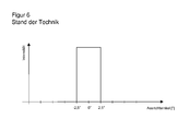
- optics with very sharp and precisely defined diaphragms are used. This leads to a FIG. 6 shown very narrow and steep intensity curve as a function of the alignment angle, in which the light emitter and light receiver to each other.
- the light signal at azimuth angles beyond the acceptance angle is zero, has very steep, nearly vertical edges at the critical angle of ⁇ 2.5 °, and is often saturated by factors on the order of 1000 times within the acceptance angle range.
- a data light barrier with two sensor units wherein the second sensor unit of the first sensor unit notifies a measured reception intensity.
- the first sensor unit indicates this as a measure of the quality of the alignment.
- this measure is only a relative measure, which is still very much of the according to DE 101 06 755 A1 unknown distance depends.
- it can be determined by pivoting with the conventional system, in which direction the adjustment is improved and deteriorated.
- it still has to be adjusted until the desired alignment is achieved, and there is no quantitative indication of the error angles.
- no requirements for Umspiegelungs none, since it ultimately does not matter if the optical transmission path is direct or indirect, and thus no acceptance angle is given.
- the invention is based on the basic idea of using instead of saturated signals those signals whose intensity profile shows a detectable dependence on the alignment angle. Then it is concluded from a measured reception intensity on the current alignment angle. The acceptance angle is now not enforced by adjustment, but set electronically by two thresholds to the measured reception intensity. If the current alignment angle does not yet fall within a range in which an intensity band is electronically adjustable due to very gross misalignment, the user can be given information as to how much the alignment still deviates from ideal alignment.
- the invention has the advantage that light is received over a much larger Ausrichtwinkel Anlagen and thereby the sensor can be mounted in accordance with tolerant Ausrichtwinkeln. A more precise alignment is not required, because the desired according to the protection class of standards acceptance angle for Umadorungsdeem be met by electronic adjustment.
- the transmission optics and / or receiving optics are much simpler, since exact apertures for setting a narrow, steep intensity profile as in FIG. 6 are dispensable.
- the Light output for the light emitters does not have to be increased, since according to the invention additionally utilized light energy is conventionally also present in larger orientation angles, but is covered by the diaphragms.
- the light transmitters are operated in smaller than the maximum possible ranges with smaller transmission currents. This also reduces infrared radiation into the environment and the influence of other systems. Conversely, the light receivers are not saturated and thus able to detect interference radiation from the outside.
- the inventively provided upper and lower threshold define an intensity band around the measured reception intensity.
- an angle band called the acceptance angle range is first placed around the current alignment angle, which fulfills the predetermined requirement of, for example, ⁇ 2.5 °.
- the intensity curve then converts between the intensity and the alignment angle.
- the sensor is aware of the complete functional relationship between alignment angle and intensity over the practically relevant angle range and with the practically relevant resolution.
- the intensity profile is preferably stored as a value table, which contains as many values as are required for the requirements on the acceptance angle.
- a calculation rule is stored which generates the function of the intensity profile. This calculation rule can also be used, for example, as the basis for the transmission current, provided that the relationship between the transmission current and the optical output power is sufficiently reliable.
- the evaluation unit is preferably designed to detect a beam interruption at an intensity of the received signal below the lower threshold and a reversal or extraneous light at an intensity of the received signal above the upper threshold.
- a light beam is considered to be uninterrupted as long as the intensity of the received signal is within the intensity band between the lower and upper threshold.
- An outbreak from the intensity band is detected and a certain minimum time may be required to distinguish events to be detected from temporary disturbances by dust or the like.
- the reception intensity drops during an object intervention by at least partial shading of the light beam, which is recognized by the lower threshold. But too much light means a mistake, because the actual light beam in its reception intensity does not increase without reason.
- Possible causes are extraneous light, which can be faded out by encoding the transmission beam, and above all a reflection, since their light from comes from the associated transmitter and therefore is also coded correctly. If the upper threshold is exceeded, no object intervention has yet taken place, but the sensor reports an error so that the reflection or other source of interference is removed.
- an intensity profile is preferably stored for different distances between the light emitter and the light receiver.
- the evaluation unit is designed to convert the intensity profile for different distances.
- an intensity profile is given at a fixed distance and transformed on the basis of the quadratic distance law.
- the distance is divided into discrete classes between minimum and maximum range of the sensor and stored for each distance class, an intensity curve, which is then interpolated on the basis of the law of distance.
- the sensor preferably has an input device for configuring the distance between the light transmitter and the light receiver. Since the absolute values of the intensity profile are evaluated and this depends strongly on the distance, the distance is parameterized to the sensor in this way.
- the evaluation unit is adapted to measure the distance between the light emitter and the light receiver. This can be done for example by a light transit time method. In a light grid there is another, in the EP 1 544 643 A1 presented option is to count the number of receivable by a light receiver light emitter, which increases with the distance.
- the sensor is specified for a fixed distance and set up.
- the acceptance angle range is configurable. Conventionally, for a different acceptance angle, for example a change from ⁇ 2.5 ° to ⁇ 5 °, the transmitting and / or receiving optics must be replaced. According to the invention, an electronic adjustment that exploits the dependence of the acceptance angle range on the distance between the lower threshold and the upper threshold is sufficient.
- the sensor preferably has a display which contains information about how much the alignment angle deviates from an ideal alignment.
- the measured during the adjustment received intensity the sensor with the aid of the intensity curve can be converted directly into an alignment angle, which is also the deviation from the ideal orientation at 0 °, in which the intensity maximum centered on the light receiver.
- the sensor outputs this numerical value in degrees an LCD display, as a color or number of an LED or the like.
- the continuous increase and decrease of the intensity curve thus makes it possible to realize a continuous electronic alignment display. With the help of this continuous display, the fitter can also quickly find the direction in which the alignment is further improved.
- alignment is not mandatory: gross misalignments in which no signal is received despite the extended angular range are visible to the naked eye, and as soon as a signal is received, the two thresholds can be set electronically without further alignment. Improved alignment, however, increases the functional reserves.
- the light transmitter and / or the light receiver preferably has a transmitting optics or a receiving optics, which ensures that the intensity of the received signal drops evenly with the alignment angle.
- a well evaluable intensity profile is achieved.
- the intensity profile is saturated for no alignment angles, whereby saturation in a small interval around 0 ° is conceivable and harmless.
- the intensity profile drops around the optimal alignment at an alignment angle of 0 ° in both directions, ie with the amount of the alignment angle, monotonically or even strictly monotonically. Evaluable intensities over larger angles are achieved than typical safety angles.
- the intensity profile thus drops only at, for example, ⁇ 5 ° or even only at ⁇ 7.5 ° or more, at ⁇ 10 ° or more, or at ⁇ 15 ° or more to a small, no longer reliably measurable value.
- the intensity profile depends uniquely on the sign, apart from a sign, from the alignment angle. Since small angle errors have no practical effect, no strict monotony needs to be demanded as long as constant portions are small. Because of the axial symmetry to the ideal alignment angle this uniqueness is given only to a sign.
- the intensity profile allows the unambiguous inference of a measured intensity on the amount of the alignment angle. Examples of an intensity course that satisfies these conditions are a Gauss curve, a parabola, a triangle, and similar functions. The most robust is a linear intensity curve, ie a triangular shape, where appropriate, a kind of dent in the top is to be provided, since an installer will try to align with the tip and this is virtually impossible with a real triangle. Alternatively, it is also conceivable to completely omit the transmitting optics and the natural beam profile of the light source or from their internal optics. This also produces a Gaussian and in any case a monotonically decreasing intensity profile on both sides.
- the evaluation unit is preferably designed to check the optical output power of the light transmitter.
- the transmission currents can first be checked.
- conventional light sources often do not reliably produce a desired optical output power for a given transmit current, but are specified only for a minimum output that can be doubled or more. Therefore, it is even more preferable to provide a receiver adjacent to the light emitter to measure the actual light output.
- a receiver adjacent to the light emitter In a light grid in which light emitters and light receivers are mixed in a bar, one of the already present adjacent light receivers can take over this task with an optical bypass. Another possibility is that the opposite receiver of the other bar measures the light output and returns this information optically coded to the first bar as in a data light barrier.
- the light output can then also be readjusted to restore the originally stored output power and thus compensate, for example, a creeping pollution.
- the alignment must be maintained, otherwise the sensor can not differentiate between alignment errors and optical output losses.
- the sensor is preferably formed as a light grid with a plurality of optoelectronic sensors with only one light beam, wherein the individual light beams are arranged parallel to each other.
- the individual light rays are also called channels.
- a light grid it is not necessary for all the components to be multiplied, but, for example, the housing, connections and evaluation unit can be shared.
- the intensity curves are, if the internal offset of the light beams remains small, equal to each other and do not necessarily have to be stored multiple times.
- a switch-off signal can be output via a safe output of the light grid if one of the received signals falls below the lower threshold or exceeds the upper threshold.
- the sensor is then a safe light grid, which acts as a non-contact protective device in safety applications is used, which spans a protective field to secure a source of danger.
- the shutdown signal silences the safety-related machine that forms the source of danger.
- the evaluation unit is preferably designed to obtain information about the orientation of the light emitter relative to the light receivers from a comparison of the intensities of a plurality of light beams.
- the maximum of the intensity distribution of all channels is located centrally on the light receiver.
- the evaluation unit calculates information in which axis the alignment is not correct, that is, whether a bar is rotated about its major axis, tilted forward or tilted sideways, and also to what extent the angle is incorrect. Due to the axial symmetry of the intensity distribution, the sign of the alignment angle can only be specified from several measurements assuming the continuity of the alignment movement. Alternatively, it is conceivable to use asymmetrical intensity distributions in a targeted manner, for example by an asymmetrical aperture, and in this way also to determine the sign.
- the plausibility of the measured intensities is checked in operation after completion of the assembly and thus with fixed alignment.
- the orientation and thus the individual expected intensities in the channels are then known, and a correlation can detect significant differences in order to improve the reliability of the individual evaluations.
- the optical output powers of the light emitters are preferably measured, and transmission currents for the light emitters are set to correspond to a desired output power.
- tolerances of the light transmitters are compensated, the specification of which often does not guarantee that the same optical output power is delivered with the same transmission current.
- the output power is known, because otherwise the assignment of alignment angle to intensity at a given distance and accordingly the threshold setting for the acceptance angle range is not correct. Since conventionally in the final production, the exit angle and the minimum intensities are checked, it means only very small and fully automatable additional effort to use the already existing measurement results for the intensity also to adjust the transmission currents.
- deviations from the parallel alignment of the light transmitters with respect to one another are measured and stored.
- the aim is that the optical axes of the light emitter are completely parallel to each other.
- the remaining tolerances can be stored by learning the actual intensity curve in the final production and compensated later during operation. For example, it is assumed that the intensity profile itself is identical in all channels and only stores an offset in the alignment angle. Alternatively, all intensity profiles are taught and thus also form different beam characteristics of the light emitter.
- FIG. 1 shows a schematic cross-sectional view of a light barrier 10.
- a transmitting part 12 includes a light emitter 14, for example an LED or a laser in the infrared or another spectrum.
- the light of the light transmitter 14 is collimated with a downstream transmitting optics 16 and sent as a light beam 18 through a monitoring area 20 to a receiving part 22.
- the light beam 18 impinges via a receiving optical system 24 on a light receiver 26, which is usually designed as a photodiode, but alternatively can also be a spatially resolving CCD or CMOS image sensor.
- the transmitting optics 16 and the receiving optics 24 can comprise further elements such as additional lenses, diaphragms and the like and ensure that the light beam 18 has a desired beam profile and consequently a predefined intensity profile as a function of an alignment angle in the transmitting part 12 and receiving part 22 are aligned with each other.
- the intensity profile without special optics is already achieved by the natural radiation or the internal structure of the light transmitter 14.
- An evaluation unit 28 is connected to the light receiver 26 and thus receives an electrical reception signal which corresponds to the intensity of the received light. With the aid of two thresholds which are derived from an intensity profile stored in a memory 28a, the evaluation unit 28 checks whether the reception intensity of the light beam 18 remains within an intensity band. If this is not the case, then the light beam 18 is interrupted or there is a reversal or interference by extraneous light. A corresponding signal is output via an output 30 of the sensor 10.
- FIG. 2 shows as a further embodiment of an optoelectronic invention, a schematic cross-sectional view of a light grid 10.
- the transmitting part 12 is formed as a transmitter strip with a plurality of arranged in a row of light emitters 14, which in each case a light receiver 26 is assigned in a trained as a receiver strip receiving part. Notwithstanding the illustration, light transmitter 14 and light receiver 26 may also be mixedly distributed on the two strips 12, 22.
- the light grid 10 is formed according to the standards mentioned above. If the evaluation unit 28 detects an intervention in the protective field 20 spanned by the light beams 18, because at least one light beam 18 is interrupted and therefore the reception intensity in the associated light receiver 26 falls below a lower threshold, then a safety-related shutdown command is transmitted via the safe output 30 (OSSD). Output Signal Switching Device). A shutdown command also occurs when the evaluation unit 28 detects an error. A particular error is the presence of a reflection which is detected by an upper threshold being exceeded.
- FIG. 3 shows an exemplary intensity curve as a function of the alignment angle.
- the transmitting part 12 and the receiving part 22 are ideally aligned with one another when the intensity maximum lies at 0 ° in the center of the light receiver 26.
- the shown intensity profile including absolute amplitude values only applies for a specific distance between transmitter part 12 and receiver part 22 and is known to evaluation unit 28. For this, the distance is first measured or entered. The evaluation unit 28 then calculates the intensity profile for the actual distance or can access the memory 28a in which the intensity profile belonging to the distance is stored.
- the transmitting part 12 and the receiving part 22 are aligned only roughly with respect to each other. Then the reception intensity 32 is measured and converted into an alignment angle with the aid of the intensity profile.
- the evaluation unit 28 places an acceptance angle range 34 around this alignment angle which, for example, corresponds to a maximum possible angular range required by the standard.
- the acceptance angle range 34 assigns the evaluation unit 28 an intensity band 36 with a lower threshold 38 and an upper threshold 40 on the basis of the intensity profile.
- the evaluation unit 28 has no way to determine from a single measurement whether it is on the rising or falling edge of the intensity profile. But this makes no practical difference, since the same thresholds 38, 40 would be set on the falling edge.
- the intensity profile should be monotonic on both sides, even linear if possible, so that the threshold distance becomes independent of the orientation.
- Flat sections in the intensity curve lead too close adjacent or even coincident thresholds 38, 40 and should therefore extend at least only over fractions of the required acceptance angle range 34.
- the evaluation unit 28 monitors whether the received signal remains between the lower threshold 38 and the upper threshold 40.
- a drop below the lower threshold 38 is interpreted as an interruption of the light beam 18 and thus as object detection.
- Exceeding the upper threshold 40 is interpreted as a mirroring. Both lead to a corresponding signal at the output 30, in the case of a safety application also to a safety-related shutdown command.
- the thresholds In order for the thresholds to be fail-safe during operation, it is necessary to regularly test whether the intensity profile stored in the evaluation unit 28 still corresponds to the actual reception intensity with undisturbed light beam 18. For this purpose, the optical output power of the light emitter 14 must be monitored.
- a display of the sensor 10 is provided in a further embodiment, which continuously indicates the current alignment angle, which was derived from the reception intensity 32. This allows the alignment to be improved quickly and purposefully. The process can be aborted at any time, and the evaluation unit 28 determines the two thresholds 38, 40 with the achieved alignment as described above.
- FIG. 4 shows several intensity courses to several channels of a light grid 10 as a function of the acceptance angle.
- the evaluation unit 28 can derive by comparison a statement about the position of transmitter strip 12 and receiver strip 22 relative to one another and indicate in which axis of rotation which alignment angles relative to ideal alignment is present. This information is again unsigned because of the symmetrical intensity curves, so it can not indicate a direction based on a measurement. Through continuous evaluation or display but can also determine the direction.
- a certain proportion of the offset of the intensity curves in FIG. 4 may be due not to the alignment but to manufacturing tolerances of the parallel alignment of the light rays 18. Therefore, it is provided in a continuation of the invention to train in the final inspection of the production of the light grid 10, as the intensity distribution is at each light transmitter 14 and light receiver 26 to a common axis. The offset of each light beam 18 thus determined can then be compensated for during operation, so that the position and rotation of the light grid 18 can be inferred from the correlation of the measured values of the various optical channels instead of manufacturing tolerances.
Landscapes
- Physics & Mathematics (AREA)
- Life Sciences & Earth Sciences (AREA)
- General Life Sciences & Earth Sciences (AREA)
- General Physics & Mathematics (AREA)
- Geophysics (AREA)
- Optical Communication System (AREA)
- Length Measuring Devices By Optical Means (AREA)
- Geophysics And Detection Of Objects (AREA)
Priority Applications (3)
| Application Number | Priority Date | Filing Date | Title |
|---|---|---|---|
| EP10154692A EP2362243B1 (fr) | 2010-02-25 | 2010-02-25 | Capteur optoélectronique |
| AT10154692T ATE557306T1 (de) | 2010-02-25 | 2010-02-25 | Optoelektronischer sensor |
| US13/033,107 US8436290B2 (en) | 2010-02-25 | 2011-02-23 | Optoelectronic sensor having an evaluation unit for determining threshold levels based on intensity distribution measurement |
Applications Claiming Priority (1)
| Application Number | Priority Date | Filing Date | Title |
|---|---|---|---|
| EP10154692A EP2362243B1 (fr) | 2010-02-25 | 2010-02-25 | Capteur optoélectronique |
Publications (2)
| Publication Number | Publication Date |
|---|---|
| EP2362243A1 true EP2362243A1 (fr) | 2011-08-31 |
| EP2362243B1 EP2362243B1 (fr) | 2012-05-09 |
Family
ID=42329980
Family Applications (1)
| Application Number | Title | Priority Date | Filing Date |
|---|---|---|---|
| EP10154692A Not-in-force EP2362243B1 (fr) | 2010-02-25 | 2010-02-25 | Capteur optoélectronique |
Country Status (3)
| Country | Link |
|---|---|
| US (1) | US8436290B2 (fr) |
| EP (1) | EP2362243B1 (fr) |
| AT (1) | ATE557306T1 (fr) |
Cited By (5)
| Publication number | Priority date | Publication date | Assignee | Title |
|---|---|---|---|---|
| EP2881762A3 (fr) * | 2013-12-05 | 2015-07-08 | Sick Ag | Capteur optoélectrique et procédé de détection d'objets brillants |
| DE102014218714A1 (de) * | 2014-09-17 | 2016-03-17 | Continental Teves Ag & Co. Ohg | Mit Lichtschranke eingepresste Messplatine im Winkelsensor |
| DE202022104647U1 (de) | 2022-08-17 | 2023-11-20 | Leuze Electronic Gmbh + Co. Kg | Optischer Sensor |
| DE102022118055A1 (de) | 2022-07-19 | 2024-01-25 | Vega Grieshaber Kg | System zum justieren/ausrichten einer messvorrichtung, verfahren zum justieren einer messvorrichtung, verwendung eines aktuators, empfängereinheit und sendereinheit |
| EP4332046A1 (fr) * | 2022-09-01 | 2024-03-06 | Cedes AG | Détection de l'inversion pour une porte de cabine d'ascenseur |
Families Citing this family (10)
| Publication number | Priority date | Publication date | Assignee | Title |
|---|---|---|---|---|
| EP2624017B1 (fr) * | 2012-02-02 | 2020-06-17 | Rockwell Automation Switzerland GmbH | Aide pour alignement de laser intégrée en employant plusieurs points laser en provenance d'un unique laser |
| US9542793B1 (en) * | 2012-11-29 | 2017-01-10 | Softronics, Ltd. | Optical sensing system |
| KR101395766B1 (ko) * | 2013-02-04 | 2014-05-16 | 동신대학교산학협력단 | 가시광선 투과율 측정 장치 |
| US10411812B1 (en) * | 2013-03-15 | 2019-09-10 | Forrest Rose | Optical interconnect computing module tolerant to changes in position and orientation |
| DE102016122364B4 (de) * | 2016-11-21 | 2022-09-08 | Sick Ag | Optoelektronischer Sensor und Verfahren zum Überwachen eines Überwachungsbereichs |
| EP3462216B1 (fr) * | 2017-09-27 | 2022-06-01 | Rockwell Automation Switzerland GmbH | Capteur optoélectronique à unité enfichable pour fournir une fonctionnalité étendue |
| EP3494786A1 (fr) | 2017-12-07 | 2019-06-12 | Bayer CropScience Aktiengesellschaft | Détection d'organismes nuisibles |
| KR102093974B1 (ko) * | 2018-12-24 | 2020-04-21 | 광전자 주식회사 | 소형 낙하물 감지용 센서 및 그 제조 방법 |
| CN111981304A (zh) * | 2019-05-23 | 2020-11-24 | 上海信索传感器有限公司 | 一种光栅及安装距离测试方法 |
| EP4307018A1 (fr) * | 2022-07-14 | 2024-01-17 | Cedes AG | Grille lumineuse à mesure de distance |
Citations (6)
| Publication number | Priority date | Publication date | Assignee | Title |
|---|---|---|---|---|
| US5393973A (en) | 1993-12-16 | 1995-02-28 | Scientific Technologies Incorporated | Optical sensing arrays employing misaligned squinted optical axes compared to aligned axes |
| DE19914114A1 (de) | 1998-03-24 | 1999-10-07 | Visolux Elektronik Gmbh | Lichtschrankenanordnung |
| EP1233283A2 (fr) * | 2001-02-14 | 2002-08-21 | Leuze electronic GmbH + Co. | Dispositif optoélectronique |
| EP1544643A1 (fr) | 2003-12-19 | 2005-06-22 | Sick Ag | Procédé et dispositif pour la surveillance d'une zone avec plusieurs émetteurs de lumière disposés côte à côte |
| DE202006012454U1 (de) | 2006-08-12 | 2006-10-26 | Sick Ag | Optoelektronischer Sensor |
| US7508512B1 (en) * | 2006-02-23 | 2009-03-24 | Rockwell Automation Technologies, Inc. | Continuous optical self-alignment for light curtains and optical presence sensors for simplification and maintenance of alignment |
-
2010
- 2010-02-25 AT AT10154692T patent/ATE557306T1/de active
- 2010-02-25 EP EP10154692A patent/EP2362243B1/fr not_active Not-in-force
-
2011
- 2011-02-23 US US13/033,107 patent/US8436290B2/en active Active
Patent Citations (8)
| Publication number | Priority date | Publication date | Assignee | Title |
|---|---|---|---|---|
| US5393973A (en) | 1993-12-16 | 1995-02-28 | Scientific Technologies Incorporated | Optical sensing arrays employing misaligned squinted optical axes compared to aligned axes |
| US5461227A (en) * | 1993-12-16 | 1995-10-24 | Scientific Technologies Incorporated | Optical sensing arrays employing misaligned squint optical ones with offset emitters and detectors compared to aligned axes |
| DE19914114A1 (de) | 1998-03-24 | 1999-10-07 | Visolux Elektronik Gmbh | Lichtschrankenanordnung |
| EP1233283A2 (fr) * | 2001-02-14 | 2002-08-21 | Leuze electronic GmbH + Co. | Dispositif optoélectronique |
| DE10106755A1 (de) | 2001-02-14 | 2002-09-12 | Leuze Electronic Gmbh & Co | Optoelekronische Vorrichtung |
| EP1544643A1 (fr) | 2003-12-19 | 2005-06-22 | Sick Ag | Procédé et dispositif pour la surveillance d'une zone avec plusieurs émetteurs de lumière disposés côte à côte |
| US7508512B1 (en) * | 2006-02-23 | 2009-03-24 | Rockwell Automation Technologies, Inc. | Continuous optical self-alignment for light curtains and optical presence sensors for simplification and maintenance of alignment |
| DE202006012454U1 (de) | 2006-08-12 | 2006-10-26 | Sick Ag | Optoelektronischer Sensor |
Cited By (6)
| Publication number | Priority date | Publication date | Assignee | Title |
|---|---|---|---|---|
| EP2881762A3 (fr) * | 2013-12-05 | 2015-07-08 | Sick Ag | Capteur optoélectrique et procédé de détection d'objets brillants |
| DE102014218714A1 (de) * | 2014-09-17 | 2016-03-17 | Continental Teves Ag & Co. Ohg | Mit Lichtschranke eingepresste Messplatine im Winkelsensor |
| DE102022118055A1 (de) | 2022-07-19 | 2024-01-25 | Vega Grieshaber Kg | System zum justieren/ausrichten einer messvorrichtung, verfahren zum justieren einer messvorrichtung, verwendung eines aktuators, empfängereinheit und sendereinheit |
| DE202022104647U1 (de) | 2022-08-17 | 2023-11-20 | Leuze Electronic Gmbh + Co. Kg | Optischer Sensor |
| EP4325257A1 (fr) * | 2022-08-17 | 2024-02-21 | Leuze electronic GmbH + Co. KG | Capteur optique |
| EP4332046A1 (fr) * | 2022-09-01 | 2024-03-06 | Cedes AG | Détection de l'inversion pour une porte de cabine d'ascenseur |
Also Published As
| Publication number | Publication date |
|---|---|
| ATE557306T1 (de) | 2012-05-15 |
| EP2362243B1 (fr) | 2012-05-09 |
| US8436290B2 (en) | 2013-05-07 |
| US20110204211A1 (en) | 2011-08-25 |
Similar Documents
| Publication | Publication Date | Title |
|---|---|---|
| EP2362243B1 (fr) | Capteur optoélectronique | |
| EP2942644B1 (fr) | Capteur télémétrique et procédé destiné à la détection et la détermination de l'éloignement d'objets | |
| DE102006060108A1 (de) | Laserscanner | |
| EP3367135B1 (fr) | Capteur optique | |
| EP2226652A1 (fr) | Capteur optoélectronique doté d'un émetteur à lampe d'orientation | |
| EP2453260B2 (fr) | Capteur de surveillance doté d'un contrôle automatique | |
| DE102015007354A1 (de) | Verfahren zur Ausrichtung eines Lichtgitters und ein Lichtgitter | |
| EP2458206A1 (fr) | Dispositif et procédé de mesure de la déformation d'une pale de rotor lors d'une charge et compensation de l'erreur | |
| DE102018117878B4 (de) | Sicherheitslichtgitter | |
| EP1717605A2 (fr) | Procédé destiné au fonctionnement d'un capteur optique | |
| DE19951557A1 (de) | Optoelektronische Vorrichtung | |
| DE202007007290U1 (de) | Optoelektronische Sensoranordnung | |
| EP3415951B1 (fr) | Capteur optique | |
| DE202018104258U1 (de) | Sicherheitslichtgitter | |
| EP1959271B1 (fr) | Agencement de capteur optoélectrique et procédé de vérification du mode de fonctionnement et/ou de l'ajustement d'un agencement de capteur optoélectronique | |
| EP3367129B1 (fr) | Capteur optoélectronique et procédé de détection d'objets | |
| EP2722692B1 (fr) | Capteur | |
| EP3623849B1 (fr) | Capteur optique | |
| EP2746821B1 (fr) | Capteur optique | |
| EP2312340B1 (fr) | Procédé de fonctionnement d'un capteur optoélectronique et capteur optoélectronique | |
| EP2746820B1 (fr) | Capteur optique | |
| EP3736605B1 (fr) | Balayeur laser de sécurité et procédé | |
| EP1962105B1 (fr) | Procédé de surveillance du type de fonction et/ou d'ajustement d'un système de capteur optoélectronique et système de capteur optoélectronique | |
| EP2578991A1 (fr) | Capteur optique | |
| EP2469223A1 (fr) | Dispositif et procédé de mesure de la déformation d'une lame de rotor lors d'une charge |
Legal Events
| Date | Code | Title | Description |
|---|---|---|---|
| PUAI | Public reference made under article 153(3) epc to a published international application that has entered the european phase |
Free format text: ORIGINAL CODE: 0009012 |
|
| 17P | Request for examination filed |
Effective date: 20100827 |
|
| AK | Designated contracting states |
Kind code of ref document: A1 Designated state(s): AT BE BG CH CY CZ DE DK EE ES FI FR GB GR HR HU IE IS IT LI LT LU LV MC MK MT NL NO PL PT RO SE SI SK SM TR |
|
| AX | Request for extension of the european patent |
Extension state: AL BA RS |
|
| GRAP | Despatch of communication of intention to grant a patent |
Free format text: ORIGINAL CODE: EPIDOSNIGR1 |
|
| GRAS | Grant fee paid |
Free format text: ORIGINAL CODE: EPIDOSNIGR3 |
|
| GRAA | (expected) grant |
Free format text: ORIGINAL CODE: 0009210 |
|
| AK | Designated contracting states |
Kind code of ref document: B1 Designated state(s): AT BE BG CH CY CZ DE DK EE ES FI FR GB GR HR HU IE IS IT LI LT LU LV MC MK MT NL NO PL PT RO SE SI SK SM TR |
|
| REG | Reference to a national code |
Ref country code: GB Ref legal event code: FG4D Free format text: NOT ENGLISH |
|
| REG | Reference to a national code |
Ref country code: AT Ref legal event code: REF Ref document number: 557306 Country of ref document: AT Kind code of ref document: T Effective date: 20120515 Ref country code: CH Ref legal event code: EP |
|
| REG | Reference to a national code |
Ref country code: IE Ref legal event code: FG4D Free format text: LANGUAGE OF EP DOCUMENT: GERMAN |
|
| REG | Reference to a national code |
Ref country code: DE Ref legal event code: R096 Ref document number: 502010000679 Country of ref document: DE Effective date: 20120705 |
|
| REG | Reference to a national code |
Ref country code: NL Ref legal event code: VDEP Effective date: 20120509 |
|
| REG | Reference to a national code |
Ref country code: LT Ref legal event code: MG4D Effective date: 20120509 |
|
| PG25 | Lapsed in a contracting state [announced via postgrant information from national office to epo] |
Ref country code: LT Free format text: LAPSE BECAUSE OF FAILURE TO SUBMIT A TRANSLATION OF THE DESCRIPTION OR TO PAY THE FEE WITHIN THE PRESCRIBED TIME-LIMIT Effective date: 20120509 Ref country code: CY Free format text: LAPSE BECAUSE OF FAILURE TO SUBMIT A TRANSLATION OF THE DESCRIPTION OR TO PAY THE FEE WITHIN THE PRESCRIBED TIME-LIMIT Effective date: 20120509 Ref country code: PL Free format text: LAPSE BECAUSE OF FAILURE TO SUBMIT A TRANSLATION OF THE DESCRIPTION OR TO PAY THE FEE WITHIN THE PRESCRIBED TIME-LIMIT Effective date: 20120509 Ref country code: NO Free format text: LAPSE BECAUSE OF FAILURE TO SUBMIT A TRANSLATION OF THE DESCRIPTION OR TO PAY THE FEE WITHIN THE PRESCRIBED TIME-LIMIT Effective date: 20120809 Ref country code: SE Free format text: LAPSE BECAUSE OF FAILURE TO SUBMIT A TRANSLATION OF THE DESCRIPTION OR TO PAY THE FEE WITHIN THE PRESCRIBED TIME-LIMIT Effective date: 20120509 Ref country code: IS Free format text: LAPSE BECAUSE OF FAILURE TO SUBMIT A TRANSLATION OF THE DESCRIPTION OR TO PAY THE FEE WITHIN THE PRESCRIBED TIME-LIMIT Effective date: 20120909 Ref country code: FI Free format text: LAPSE BECAUSE OF FAILURE TO SUBMIT A TRANSLATION OF THE DESCRIPTION OR TO PAY THE FEE WITHIN THE PRESCRIBED TIME-LIMIT Effective date: 20120509 |
|
| PG25 | Lapsed in a contracting state [announced via postgrant information from national office to epo] |
Ref country code: SI Free format text: LAPSE BECAUSE OF FAILURE TO SUBMIT A TRANSLATION OF THE DESCRIPTION OR TO PAY THE FEE WITHIN THE PRESCRIBED TIME-LIMIT Effective date: 20120509 Ref country code: LV Free format text: LAPSE BECAUSE OF FAILURE TO SUBMIT A TRANSLATION OF THE DESCRIPTION OR TO PAY THE FEE WITHIN THE PRESCRIBED TIME-LIMIT Effective date: 20120509 Ref country code: HR Free format text: LAPSE BECAUSE OF FAILURE TO SUBMIT A TRANSLATION OF THE DESCRIPTION OR TO PAY THE FEE WITHIN THE PRESCRIBED TIME-LIMIT Effective date: 20120509 Ref country code: PT Free format text: LAPSE BECAUSE OF FAILURE TO SUBMIT A TRANSLATION OF THE DESCRIPTION OR TO PAY THE FEE WITHIN THE PRESCRIBED TIME-LIMIT Effective date: 20120910 Ref country code: GR Free format text: LAPSE BECAUSE OF FAILURE TO SUBMIT A TRANSLATION OF THE DESCRIPTION OR TO PAY THE FEE WITHIN THE PRESCRIBED TIME-LIMIT Effective date: 20120810 |
|
| PG25 | Lapsed in a contracting state [announced via postgrant information from national office to epo] |
Ref country code: EE Free format text: LAPSE BECAUSE OF FAILURE TO SUBMIT A TRANSLATION OF THE DESCRIPTION OR TO PAY THE FEE WITHIN THE PRESCRIBED TIME-LIMIT Effective date: 20120509 Ref country code: CZ Free format text: LAPSE BECAUSE OF FAILURE TO SUBMIT A TRANSLATION OF THE DESCRIPTION OR TO PAY THE FEE WITHIN THE PRESCRIBED TIME-LIMIT Effective date: 20120509 Ref country code: DK Free format text: LAPSE BECAUSE OF FAILURE TO SUBMIT A TRANSLATION OF THE DESCRIPTION OR TO PAY THE FEE WITHIN THE PRESCRIBED TIME-LIMIT Effective date: 20120509 Ref country code: NL Free format text: LAPSE BECAUSE OF FAILURE TO SUBMIT A TRANSLATION OF THE DESCRIPTION OR TO PAY THE FEE WITHIN THE PRESCRIBED TIME-LIMIT Effective date: 20120509 Ref country code: RO Free format text: LAPSE BECAUSE OF FAILURE TO SUBMIT A TRANSLATION OF THE DESCRIPTION OR TO PAY THE FEE WITHIN THE PRESCRIBED TIME-LIMIT Effective date: 20120509 Ref country code: SK Free format text: LAPSE BECAUSE OF FAILURE TO SUBMIT A TRANSLATION OF THE DESCRIPTION OR TO PAY THE FEE WITHIN THE PRESCRIBED TIME-LIMIT Effective date: 20120509 |
|
| PG25 | Lapsed in a contracting state [announced via postgrant information from national office to epo] |
Ref country code: IT Free format text: LAPSE BECAUSE OF FAILURE TO SUBMIT A TRANSLATION OF THE DESCRIPTION OR TO PAY THE FEE WITHIN THE PRESCRIBED TIME-LIMIT Effective date: 20120509 |
|
| PLBE | No opposition filed within time limit |
Free format text: ORIGINAL CODE: 0009261 |
|
| STAA | Information on the status of an ep patent application or granted ep patent |
Free format text: STATUS: NO OPPOSITION FILED WITHIN TIME LIMIT |
|
| 26N | No opposition filed |
Effective date: 20130212 |
|
| REG | Reference to a national code |
Ref country code: DE Ref legal event code: R097 Ref document number: 502010000679 Country of ref document: DE Effective date: 20130212 |
|
| PG25 | Lapsed in a contracting state [announced via postgrant information from national office to epo] |
Ref country code: BG Free format text: LAPSE BECAUSE OF FAILURE TO SUBMIT A TRANSLATION OF THE DESCRIPTION OR TO PAY THE FEE WITHIN THE PRESCRIBED TIME-LIMIT Effective date: 20120809 |
|
| BERE | Be: lapsed |
Owner name: SICK A.G. Effective date: 20130228 |
|
| PG25 | Lapsed in a contracting state [announced via postgrant information from national office to epo] |
Ref country code: MC Free format text: LAPSE BECAUSE OF NON-PAYMENT OF DUE FEES Effective date: 20130228 |
|
| PG25 | Lapsed in a contracting state [announced via postgrant information from national office to epo] |
Ref country code: ES Free format text: LAPSE BECAUSE OF FAILURE TO SUBMIT A TRANSLATION OF THE DESCRIPTION OR TO PAY THE FEE WITHIN THE PRESCRIBED TIME-LIMIT Effective date: 20120820 |
|
| REG | Reference to a national code |
Ref country code: IE Ref legal event code: MM4A |
|
| PG25 | Lapsed in a contracting state [announced via postgrant information from national office to epo] |
Ref country code: IE Free format text: LAPSE BECAUSE OF NON-PAYMENT OF DUE FEES Effective date: 20130225 Ref country code: BE Free format text: LAPSE BECAUSE OF NON-PAYMENT OF DUE FEES Effective date: 20130228 |
|
| PG25 | Lapsed in a contracting state [announced via postgrant information from national office to epo] |
Ref country code: MT Free format text: LAPSE BECAUSE OF FAILURE TO SUBMIT A TRANSLATION OF THE DESCRIPTION OR TO PAY THE FEE WITHIN THE PRESCRIBED TIME-LIMIT Effective date: 20120509 |
|
| REG | Reference to a national code |
Ref country code: FR Ref legal event code: PLFP Year of fee payment: 6 |
|
| PG25 | Lapsed in a contracting state [announced via postgrant information from national office to epo] |
Ref country code: SM Free format text: LAPSE BECAUSE OF FAILURE TO SUBMIT A TRANSLATION OF THE DESCRIPTION OR TO PAY THE FEE WITHIN THE PRESCRIBED TIME-LIMIT Effective date: 20120509 |
|
| PGFP | Annual fee paid to national office [announced via postgrant information from national office to epo] |
Ref country code: GB Payment date: 20150223 Year of fee payment: 6 Ref country code: FR Payment date: 20150217 Year of fee payment: 6 |
|
| PG25 | Lapsed in a contracting state [announced via postgrant information from national office to epo] |
Ref country code: TR Free format text: LAPSE BECAUSE OF FAILURE TO SUBMIT A TRANSLATION OF THE DESCRIPTION OR TO PAY THE FEE WITHIN THE PRESCRIBED TIME-LIMIT Effective date: 20120509 |
|
| PG25 | Lapsed in a contracting state [announced via postgrant information from national office to epo] |
Ref country code: MK Free format text: LAPSE BECAUSE OF FAILURE TO SUBMIT A TRANSLATION OF THE DESCRIPTION OR TO PAY THE FEE WITHIN THE PRESCRIBED TIME-LIMIT Effective date: 20120509 Ref country code: HU Free format text: LAPSE BECAUSE OF FAILURE TO SUBMIT A TRANSLATION OF THE DESCRIPTION OR TO PAY THE FEE WITHIN THE PRESCRIBED TIME-LIMIT; INVALID AB INITIO Effective date: 20100225 Ref country code: LU Free format text: LAPSE BECAUSE OF NON-PAYMENT OF DUE FEES Effective date: 20130225 |
|
| REG | Reference to a national code |
Ref country code: AT Ref legal event code: MM01 Ref document number: 557306 Country of ref document: AT Kind code of ref document: T Effective date: 20150225 |
|
| PGFP | Annual fee paid to national office [announced via postgrant information from national office to epo] |
Ref country code: CH Payment date: 20160222 Year of fee payment: 7 |
|
| PG25 | Lapsed in a contracting state [announced via postgrant information from national office to epo] |
Ref country code: AT Free format text: LAPSE BECAUSE OF NON-PAYMENT OF DUE FEES Effective date: 20150225 |
|
| GBPC | Gb: european patent ceased through non-payment of renewal fee |
Effective date: 20160225 |
|
| REG | Reference to a national code |
Ref country code: FR Ref legal event code: ST Effective date: 20161028 |
|
| PG25 | Lapsed in a contracting state [announced via postgrant information from national office to epo] |
Ref country code: GB Free format text: LAPSE BECAUSE OF NON-PAYMENT OF DUE FEES Effective date: 20160225 Ref country code: FR Free format text: LAPSE BECAUSE OF NON-PAYMENT OF DUE FEES Effective date: 20160229 |
|
| REG | Reference to a national code |
Ref country code: CH Ref legal event code: PL |
|
| PG25 | Lapsed in a contracting state [announced via postgrant information from national office to epo] |
Ref country code: CH Free format text: LAPSE BECAUSE OF NON-PAYMENT OF DUE FEES Effective date: 20170228 Ref country code: LI Free format text: LAPSE BECAUSE OF NON-PAYMENT OF DUE FEES Effective date: 20170228 |
|
| PGFP | Annual fee paid to national office [announced via postgrant information from national office to epo] |
Ref country code: DE Payment date: 20200220 Year of fee payment: 11 |
|
| REG | Reference to a national code |
Ref country code: DE Ref legal event code: R119 Ref document number: 502010000679 Country of ref document: DE |
|
| PG25 | Lapsed in a contracting state [announced via postgrant information from national office to epo] |
Ref country code: DE Free format text: LAPSE BECAUSE OF NON-PAYMENT OF DUE FEES Effective date: 20210901 |