EP2362231A1 - Out-of-plane comb-drive accelerometer - Google Patents
Out-of-plane comb-drive accelerometer Download PDFInfo
- Publication number
- EP2362231A1 EP2362231A1 EP10192293A EP10192293A EP2362231A1 EP 2362231 A1 EP2362231 A1 EP 2362231A1 EP 10192293 A EP10192293 A EP 10192293A EP 10192293 A EP10192293 A EP 10192293A EP 2362231 A1 EP2362231 A1 EP 2362231A1
- Authority
- EP
- European Patent Office
- Prior art keywords
- rotor
- tines
- substrate
- distance
- stator
- Prior art date
- Legal status (The legal status is an assumption and is not a legal conclusion. Google has not performed a legal analysis and makes no representation as to the accuracy of the status listed.)
- Withdrawn
Links
- 239000000758 substrate Substances 0.000 claims abstract description 22
- 230000001133 acceleration Effects 0.000 claims description 6
- 244000126211 Hericium coralloides Species 0.000 description 11
- 210000001520 comb Anatomy 0.000 description 7
- 230000000694 effects Effects 0.000 description 3
- 230000007613 environmental effect Effects 0.000 description 3
- 230000035945 sensitivity Effects 0.000 description 3
- 230000003247 decreasing effect Effects 0.000 description 1
- 238000006073 displacement reaction Methods 0.000 description 1
- 238000005530 etching Methods 0.000 description 1
- 230000000873 masking effect Effects 0.000 description 1
- 238000000034 method Methods 0.000 description 1
Images
Classifications
-
- G—PHYSICS
- G01—MEASURING; TESTING
- G01P—MEASURING LINEAR OR ANGULAR SPEED, ACCELERATION, DECELERATION, OR SHOCK; INDICATING PRESENCE, ABSENCE, OR DIRECTION, OF MOVEMENT
- G01P15/00—Measuring acceleration; Measuring deceleration; Measuring shock, i.e. sudden change of acceleration
- G01P15/02—Measuring acceleration; Measuring deceleration; Measuring shock, i.e. sudden change of acceleration by making use of inertia forces using solid seismic masses
- G01P15/08—Measuring acceleration; Measuring deceleration; Measuring shock, i.e. sudden change of acceleration by making use of inertia forces using solid seismic masses with conversion into electric or magnetic values
- G01P15/125—Measuring acceleration; Measuring deceleration; Measuring shock, i.e. sudden change of acceleration by making use of inertia forces using solid seismic masses with conversion into electric or magnetic values by capacitive pick-up
-
- G—PHYSICS
- G01—MEASURING; TESTING
- G01P—MEASURING LINEAR OR ANGULAR SPEED, ACCELERATION, DECELERATION, OR SHOCK; INDICATING PRESENCE, ABSENCE, OR DIRECTION, OF MOVEMENT
- G01P15/00—Measuring acceleration; Measuring deceleration; Measuring shock, i.e. sudden change of acceleration
- G01P15/02—Measuring acceleration; Measuring deceleration; Measuring shock, i.e. sudden change of acceleration by making use of inertia forces using solid seismic masses
- G01P15/08—Measuring acceleration; Measuring deceleration; Measuring shock, i.e. sudden change of acceleration by making use of inertia forces using solid seismic masses with conversion into electric or magnetic values
- G01P15/13—Measuring acceleration; Measuring deceleration; Measuring shock, i.e. sudden change of acceleration by making use of inertia forces using solid seismic masses with conversion into electric or magnetic values by measuring the force required to restore a proofmass subjected to inertial forces to a null position
- G01P15/131—Measuring acceleration; Measuring deceleration; Measuring shock, i.e. sudden change of acceleration by making use of inertia forces using solid seismic masses with conversion into electric or magnetic values by measuring the force required to restore a proofmass subjected to inertial forces to a null position with electrostatic counterbalancing means
Definitions
- Out-of-plane micro-electromechanical systems (MEMS) accelerometers typically use parallel plate capacitance pickoff sensing (sense) for open-loop devices and parallel plate capacitance rebalance (torque) for closed-loop devices. Both types of sensors are composed of two parallel plates separated by a narrow gap and having a voltage applied across them. In either case, the functionality of the device derives from the variation in capacitance that occurs when the distance across the gap changes under acceleration.
- the present invention includes an accelerometer for linearizing a response.
- An example accelerometer includes a substrate with one or more stators fixedly attached to the substrate.
- the stators include a plurality of tines having a surface parallel to a surface of the substrate.
- the tine surface is at a first distance from the surface of the substrate.
- a proof mass is rotatably attached to the substrate.
- the proof mass includes one or more rotors that include a plurality of rotor tines attached to an edge of the proof mass.
- the rotor tines are interleaved with corresponding ones of the stator tines.
- the rotor tines include a surface parallel to a surface of the substrate.
- the rotor tine surface is at a second distance from the surface of the substrate. The first distance and second distance are unequal by a threshold amount.
- motion of the rotor relative to the stator in an out-of-plane direction provides a linear change in a capacitive value measured across the rotor and the stator, thus minimizing the effect of external environmental influences.
- FIGURE 1 illustrates a perspective view of an example system formed in accordance with an embodiment of the present invention
- FIGURE 2 illustrates a perspective view of a portion of an example system formed in accordance with an embodiment of the present invention.
- FIGURE 3 illustrates a cross-sectional view of an example system formed in accordance with an embodiment of the present invention.
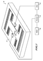
- FIGURE 1 illustrates an example out-of-plane comb-drive accelerometer 10.
- the out-of-plane comb-drive accelerometer 10 includes a micro-electromechanical system (MEMS) comb-tooth structure 14, a processor 18, a drive circuit 22, and an output device 26.
- MEMS micro-electromechanical system
- the comb-tooth structure 14, the processor 18, and the drive circuit 22 are communicatively coupled in a loop.
- the processor 18 is in signal communication with the output device 26.
- the out-of-plane comb-drive accelerometer 10 operates in closed-loop fashion.
- the comb-drive accelerometer 10 experiences acceleration or rotation in a direction perpendicular to the plane of the comb-tooth structure 14
- variation in a sense capacitance within the comb-tooth structure 14 is sensed as a change in voltage by the processor 18.
- the processor 18 responds to the voltage change by varying a feedback signal it outputs to the drive circuit 22.
- the feedback signal is continuously adjusted by the processor 18 to continuously drive drive components of the comb-tooth structure 14 toward an equilibrium (null) position.
- the voltage level required to compensate for the variation in capacitance is proportional to the acceleration experienced by the comb-drive structure 14.
- the processor 18 outputs a signal to the output device 26 that corresponds to the signal sent to the drive components.
- the output device 26 receives the signal from the processor 18 and outputs displays as the measured acceleration or rotation rate.
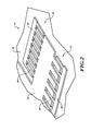
- FIGURE 2 illustrates a portion of the MEMS comb-tooth structure 14 used in the accelerometer 10.
- the comb-tooth structure 14 includes one or more sense combs 30 and one or more drive combs 34.
- the sense comb 30 includes a sense comb rotor 38 and a sense comb stator 42.
- the drive comb 34 includes a drive comb rotor 46 and a drive comb stator 50.
- the rotors 38, 46 are electrically isolated tines located on a proof mass 54.
- the stators 42, 50 are attached to a base substrate 58 of the comb-tooth structure 14.
- the stators 42, 50 are electrically isolated from each other.
- the rotors 38, 46 and the stators 42, 50 are substantially planar structures, each having a row of tines.
- the rotors 38, 46 and the stators 42, 50 are arranged so that they occupy substantially the same plane, but with at least a minimal offset in the out-of-plane direction (e.g., perpendicular to the surface).
- the tines of the rotors 38, 46 are interleaved with the tines of the stators 42, 50. Between the tines is a gap across which a capacitance is measured.
- the proof mass 54 is suspended above the base substrate 58 on flexural supports located remotely from the combs 30, 34 in a see-saw manner.
- the flexural supports allow the proof mass 54 and, therefore, the tines of the rotors 38, 46, to move vertically (out of plane) with respect to the tines of the stators 42, 50. Motion in this direction does not change the gap between the rotors 38, 46 and the stators 42, 50, but directly leads to variation in the area of overlap between the tines of the rotors 38, 46 and the stators 42, 50.
- the area of overlap is specifically the portions of the sidewalls of the rotor and stator tines that face one another across the gap.
- the capacitance varies. Because the area of overlap varies linearly with movement of the rotor tines past the stator tines, the variation in capacitance is also linear. The effect provides the comb-tooth structure 14 with decreased sensitivity to the influence of environmental noise, such as thermal variation and vibration.
- the processor 18 is coupled to one of the stator and rotor of the sense combs 30.
- the drive circuit 22 is coupled to one of the stator and rotor of the drive combs 34.
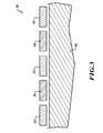
- FIGURE 3 illustrates an example offset between the tines of one of the rotors 38 and tines of one of the stators 42 for the sense comb 30.
- the offset is in the same direction as the to-be-sensed acceleration.
- the tines are offset during an etching/masking process.
- the sensitivity of the comb tooth structure 14 is determined by the gap between the combs.
- the linearity is determined by the ratio of the offset to the thickness.
- the ratio between stator thickness and the magnitude of the offset is optimized in order to maintain a linear response, and thereby minimize the sensitivity of the device to thermal effects and vibration.
- the offset must occur along both the top and bottom edges.
- the stator and rotor can be of different thicknesses, but this may affect the linearity of the mechanism.
- the ratio between thickness and offset is determined by the point at which small displacements in the mechanism will produce minimal changes in the electrical fringe fields at the top and bottom of the combs. This corresponds to having equal lengths for the top and bottom offsets and the overlapping structure in the middle of the comb thickness.
Landscapes
- Physics & Mathematics (AREA)
- General Physics & Mathematics (AREA)
- Pressure Sensors (AREA)
- Micromachines (AREA)
Applications Claiming Priority (1)
| Application Number | Priority Date | Filing Date | Title |
|---|---|---|---|
| US12/709,184 US8505380B2 (en) | 2010-02-19 | 2010-02-19 | Out-of plane comb-drive accelerometer |
Publications (1)
| Publication Number | Publication Date |
|---|---|
| EP2362231A1 true EP2362231A1 (en) | 2011-08-31 |
Family
ID=44006900
Family Applications (1)
| Application Number | Title | Priority Date | Filing Date |
|---|---|---|---|
| EP10192293A Withdrawn EP2362231A1 (en) | 2010-02-19 | 2010-11-23 | Out-of-plane comb-drive accelerometer |
Country Status (3)
| Country | Link |
|---|---|
| US (1) | US8505380B2 (enExample) |
| EP (1) | EP2362231A1 (enExample) |
| JP (1) | JP5759154B2 (enExample) |
Families Citing this family (4)
| Publication number | Priority date | Publication date | Assignee | Title |
|---|---|---|---|---|
| JP5967018B2 (ja) * | 2013-05-31 | 2016-08-10 | 株式会社デンソー | 容量式物理量センサ |
| WO2017160995A1 (en) * | 2016-03-16 | 2017-09-21 | Roger Laine | Cyclohexylamine-based compounds and uses thereof |
| CN113702664B (zh) * | 2021-07-20 | 2023-03-10 | 北京航天控制仪器研究所 | 一种宽频带mems加速度计及其制备方法 |
| EP4428542B1 (en) * | 2023-03-07 | 2025-06-18 | Murata Manufacturing Co., Ltd. | In-plane and out-of-plane accelerometer |
Citations (3)
| Publication number | Priority date | Publication date | Assignee | Title |
|---|---|---|---|---|
| US6000280A (en) * | 1995-07-20 | 1999-12-14 | Cornell Research Foundation, Inc. | Drive electrodes for microfabricated torsional cantilevers |
| EP2151691A2 (en) * | 2008-07-31 | 2010-02-10 | Honeywell International Inc. | Systems and methods for detecting out-of-plane linear acceleration with a closed loop linear drive accelerometer |
| EP2267461A1 (en) * | 2009-06-26 | 2010-12-29 | Honeywell International Inc. | Bidirectional, out-of-plane, comb drive accelerometer |
Family Cites Families (8)
| Publication number | Priority date | Publication date | Assignee | Title |
|---|---|---|---|---|
| US6199874B1 (en) * | 1993-05-26 | 2001-03-13 | Cornell Research Foundation Inc. | Microelectromechanical accelerometer for automotive applications |
| US6230566B1 (en) * | 1999-10-01 | 2001-05-15 | The Regents Of The University Of California | Micromachined low frequency rocking accelerometer with capacitive pickoff |
| JP2006170704A (ja) * | 2004-12-14 | 2006-06-29 | Mitsubishi Electric Corp | 容量型加速度検出装置 |
| US7258010B2 (en) * | 2005-03-09 | 2007-08-21 | Honeywell International Inc. | MEMS device with thinned comb fingers |
| US7469588B2 (en) * | 2006-05-16 | 2008-12-30 | Honeywell International Inc. | MEMS vertical comb drive with improved vibration performance |
| JP2008292426A (ja) * | 2007-05-28 | 2008-12-04 | Panasonic Electric Works Co Ltd | 静電容量式センサ |
| US7690254B2 (en) * | 2007-07-26 | 2010-04-06 | Honeywell International Inc. | Sensor with position-independent drive electrodes in multi-layer silicon on insulator substrate |
| US7578190B2 (en) * | 2007-08-03 | 2009-08-25 | Freescale Semiconductor, Inc. | Symmetrical differential capacitive sensor and method of making same |
-
2010
- 2010-02-19 US US12/709,184 patent/US8505380B2/en active Active
- 2010-11-23 EP EP10192293A patent/EP2362231A1/en not_active Withdrawn
- 2010-12-01 JP JP2010268287A patent/JP5759154B2/ja not_active Expired - Fee Related
Patent Citations (3)
| Publication number | Priority date | Publication date | Assignee | Title |
|---|---|---|---|---|
| US6000280A (en) * | 1995-07-20 | 1999-12-14 | Cornell Research Foundation, Inc. | Drive electrodes for microfabricated torsional cantilevers |
| EP2151691A2 (en) * | 2008-07-31 | 2010-02-10 | Honeywell International Inc. | Systems and methods for detecting out-of-plane linear acceleration with a closed loop linear drive accelerometer |
| EP2267461A1 (en) * | 2009-06-26 | 2010-12-29 | Honeywell International Inc. | Bidirectional, out-of-plane, comb drive accelerometer |
Also Published As
| Publication number | Publication date |
|---|---|
| US20110203372A1 (en) | 2011-08-25 |
| JP5759154B2 (ja) | 2015-08-05 |
| US8505380B2 (en) | 2013-08-13 |
| JP2011169889A (ja) | 2011-09-01 |
Similar Documents
| Publication | Publication Date | Title |
|---|---|---|
| EP2697607B1 (en) | Accelerometer systems and methods | |
| US11377346B2 (en) | Low-noise multi axis MEMS accelerometer | |
| JP2765316B2 (ja) | 容量型三軸加速度センサ | |
| US20020189355A1 (en) | Small size, high capacitance readout silicon based MEMS accelerometer | |
| US20060169041A1 (en) | Combined gyroscope and 2-axis accelerometer | |
| US20150268268A1 (en) | Inertial sensor with trim capacitance and method of trimming offset | |
| CN108450010B (zh) | 改进的微机电加速计装置 | |
| US10024881B2 (en) | MEMS sensor | |
| EP3151018B1 (en) | Mems sensor with reduced cross-axis sensitivity | |
| JPH05340960A (ja) | 多次元加速度センサ | |
| JP2018531377A6 (ja) | 改良型微小電気機械加速度測定装置 | |
| US8505380B2 (en) | Out-of plane comb-drive accelerometer | |
| EP3226006B1 (en) | Accelerometer sensor system | |
| KR20210053194A (ko) | 용량성 가속도계의 폐루프 동작을 위한 방법 | |
| EP2455327B1 (en) | A mems vertical comb structure with linear drive / pickoff | |
| CN114966107B (zh) | 用于使基于温度的误差减少的锚定结构 | |
| Mukherjee et al. | A simple low cost scheme for closed loop operation of MEMS capacitive accelerometer | |
| FI3980793T3 (fi) | Kiihtyvyysanturilaite, jossa on paranneltu poikkeamastabilteetti | |
| JPH08261850A (ja) | 多次元方向に関する力・加速度・磁気の検出装置 | |
| KR20090103795A (ko) | 평면외 mems 장치로부터 가속 및 회전 판단을 위한 시스템 및 방법 |
Legal Events
| Date | Code | Title | Description |
|---|---|---|---|
| PUAI | Public reference made under article 153(3) epc to a published international application that has entered the european phase |
Free format text: ORIGINAL CODE: 0009012 |
|
| 17P | Request for examination filed |
Effective date: 20101123 |
|
| AK | Designated contracting states |
Kind code of ref document: A1 Designated state(s): AL AT BE BG CH CY CZ DE DK EE ES FI FR GB GR HR HU IE IS IT LI LT LU LV MC MK MT NL NO PL PT RO RS SE SI SK SM TR |
|
| AX | Request for extension of the european patent |
Extension state: BA ME |
|
| 17Q | First examination report despatched |
Effective date: 20110824 |
|
| RAP1 | Party data changed (applicant data changed or rights of an application transferred) |
Owner name: HONEYWELL INTERNATIONAL INC. |
|
| STAA | Information on the status of an ep patent application or granted ep patent |
Free format text: STATUS: THE APPLICATION IS DEEMED TO BE WITHDRAWN |
|
| 18D | Application deemed to be withdrawn |
Effective date: 20190601 |