EP2362178A1 - Capacitance-type sensor - Google Patents
Capacitance-type sensor Download PDFInfo
- Publication number
- EP2362178A1 EP2362178A1 EP09823717A EP09823717A EP2362178A1 EP 2362178 A1 EP2362178 A1 EP 2362178A1 EP 09823717 A EP09823717 A EP 09823717A EP 09823717 A EP09823717 A EP 09823717A EP 2362178 A1 EP2362178 A1 EP 2362178A1
- Authority
- EP
- European Patent Office
- Prior art keywords
- sensor
- electrodes
- capacitance
- guard
- potential
- Prior art date
- Legal status (The legal status is an assumption and is not a legal conclusion. Google has not performed a legal analysis and makes no representation as to the accuracy of the status listed.)
- Withdrawn
Links
Images


Classifications
-
- G—PHYSICS
- G01—MEASURING; TESTING
- G01B—MEASURING LENGTH, THICKNESS OR SIMILAR LINEAR DIMENSIONS; MEASURING ANGLES; MEASURING AREAS; MEASURING IRREGULARITIES OF SURFACES OR CONTOURS
- G01B7/00—Measuring arrangements characterised by the use of electric or magnetic techniques
- G01B7/02—Measuring arrangements characterised by the use of electric or magnetic techniques for measuring length, width or thickness
- G01B7/023—Measuring arrangements characterised by the use of electric or magnetic techniques for measuring length, width or thickness for measuring distance between sensor and object
-
- B—PERFORMING OPERATIONS; TRANSPORTING
- B60—VEHICLES IN GENERAL
- B60R—VEHICLES, VEHICLE FITTINGS, OR VEHICLE PARTS, NOT OTHERWISE PROVIDED FOR
- B60R21/00—Arrangements or fittings on vehicles for protecting or preventing injuries to occupants or pedestrians in case of accidents or other traffic risks
- B60R21/01—Electrical circuits for triggering passive safety arrangements, e.g. airbags, safety belt tighteners, in case of vehicle accidents or impending vehicle accidents
- B60R21/015—Electrical circuits for triggering passive safety arrangements, e.g. airbags, safety belt tighteners, in case of vehicle accidents or impending vehicle accidents including means for detecting the presence or position of passengers, passenger seats or child seats, and the related safety parameters therefor, e.g. speed or timing of airbag inflation in relation to occupant position or seat belt use
- B60R21/01512—Passenger detection systems
- B60R21/01516—Passenger detection systems using force or pressure sensing means
- B60R21/0152—Passenger detection systems using force or pressure sensing means using strain gauges
-
- B—PERFORMING OPERATIONS; TRANSPORTING
- B60—VEHICLES IN GENERAL
- B60R—VEHICLES, VEHICLE FITTINGS, OR VEHICLE PARTS, NOT OTHERWISE PROVIDED FOR
- B60R21/00—Arrangements or fittings on vehicles for protecting or preventing injuries to occupants or pedestrians in case of accidents or other traffic risks
- B60R21/01—Electrical circuits for triggering passive safety arrangements, e.g. airbags, safety belt tighteners, in case of vehicle accidents or impending vehicle accidents
- B60R21/015—Electrical circuits for triggering passive safety arrangements, e.g. airbags, safety belt tighteners, in case of vehicle accidents or impending vehicle accidents including means for detecting the presence or position of passengers, passenger seats or child seats, and the related safety parameters therefor, e.g. speed or timing of airbag inflation in relation to occupant position or seat belt use
- B60R21/01512—Passenger detection systems
- B60R21/0153—Passenger detection systems using field detection presence sensors
- B60R21/01532—Passenger detection systems using field detection presence sensors using electric or capacitive field sensors
-
- B—PERFORMING OPERATIONS; TRANSPORTING
- B60—VEHICLES IN GENERAL
- B60R—VEHICLES, VEHICLE FITTINGS, OR VEHICLE PARTS, NOT OTHERWISE PROVIDED FOR
- B60R21/00—Arrangements or fittings on vehicles for protecting or preventing injuries to occupants or pedestrians in case of accidents or other traffic risks
- B60R21/02—Occupant safety arrangements or fittings, e.g. crash pads
- B60R21/055—Padded or energy-absorbing fittings, e.g. seat belt anchors
-
- B—PERFORMING OPERATIONS; TRANSPORTING
- B60—VEHICLES IN GENERAL
- B60R—VEHICLES, VEHICLE FITTINGS, OR VEHICLE PARTS, NOT OTHERWISE PROVIDED FOR
- B60R25/00—Fittings or systems for preventing or indicating unauthorised use or theft of vehicles
-
- G—PHYSICS
- G01—MEASURING; TESTING
- G01B—MEASURING LENGTH, THICKNESS OR SIMILAR LINEAR DIMENSIONS; MEASURING ANGLES; MEASURING AREAS; MEASURING IRREGULARITIES OF SURFACES OR CONTOURS
- G01B7/00—Measuring arrangements characterised by the use of electric or magnetic techniques
-
- G—PHYSICS
- G01—MEASURING; TESTING
- G01B—MEASURING LENGTH, THICKNESS OR SIMILAR LINEAR DIMENSIONS; MEASURING ANGLES; MEASURING AREAS; MEASURING IRREGULARITIES OF SURFACES OR CONTOURS
- G01B7/00—Measuring arrangements characterised by the use of electric or magnetic techniques
- G01B7/28—Measuring arrangements characterised by the use of electric or magnetic techniques for measuring contours or curvatures
Definitions
- the present invention relates to a capacitance-type sensor which senses a capacitance with respect to a sensing target existing in a sensing area, and particularly to a capacitance-type sensor which can sense the position of the sensing target in the sensing area highly precisely.
- a headrest driving device disclosed in Patent Document 1 identified below includes: support means which supports a headrest movably; driving means which drives the headrest reciprocatingly; a plurality of detecting electrodes (sensing electrodes) which are provided inside an external cover of the headrest at a portion for supporting a head and at a distance from each other; capacitance detecting means which detects capacitances formed by these plurality of detecting electrodes with respect to a common potential line; and position controlling means which controls the driving means to drive the headrest to move in a direction to bring the capacitances into balance.
- the headrest is driven by the driving means controlled by the position controlling means in such a way that the head comes to be located at the middle position between the plurality of detecting electrodes, in other words, in such a way that the headrest is moved in accordance with the movement of the head, whereby the position of the headrest is adjusted automatically.
- a device for adjusting a headrest disclosed in Patent Document 2 identified below is configured by a sensor including two capacitor plates which are provided inside the headrest for sensing the position of the head of a vehicle occupant. These two capacitor plates are arranged one above the other inside the headrest.
- a position of the headrest in height is adjusted in such a manner as to be changed from a home position where the headrest is retracted.
- a headrest adjusting device disclosed in Patent Document 3 identified below includes: a headrest provided above a seat back (backrest) to be movable upward and downward by being driven by a motor; a head detecting sensor which detects the position of the head of a sitting person (vehicle occupant); and a CPU which adjusts the height of the headrest to match the position of the head of the sitting person based on a signal from the head detecting sensor.
- This headrest adjusting device starts the operation of adjusting the headrest when the CPU senses an electrical conduction of an ignition switch, a sitting sensor senses sitting, and a seatbelt buckle switch senses fastening of a seatbelt of the vehicle.
- An object detecting device disclosed in Patent Document 4 identified below includes a sensor electrode unit which is formed by inserting a plurality of sensor electrodes arranged at regular intervals into a resin and insert-molding the electrodes.
- This sensor electrode unit is hollow, has a generally rectangular cross-sectional shape, and has the sensor electrodes provided on at least one side of the rectangle, which improves the latitude of installation while maintaining the detection performance.
- the headrest driving device disclosed in Patent Document 1 identified above adjusts the position of the headrest based on capacitances between the headrest and a ceiling portion, etc. of a vehicle.
- the device for adjusting a headrest disclosed in Patent Document 2 identified above measures capacitances between a head and sensing electrodes by means of two or three capacitor plates and uses the capacitances for position adjustment.
- the headrest position adjusting device disclosed in Patent Document 3 identified above performs position adjustment for the headrest according to results of adjustments of each portion of the seat.
- the object detecting device disclosed in Patent Document 4 identified above can sense capacitances by means of the sensor electrodes stably if, for example, the middle position among the plurality of sensor electrodes faces the exact center of a sensing target.
- the conventional techniques have to sense an object by comparing the outputs from the sensors for balancing them or comparing the peaks of the outputs from the sensing electrodes.
- the initial capacitances of the sensing electrodes i.e., the capacitance values when no sensing target is existing
- the sensing sensitivities thereof might greatly vary depending on, for example, the positions at which the plurality of sensing electrodes are provided.
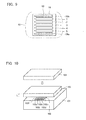
- a sensor unit 102 configured by a plurality of sensor electrodes 102a to 102e formed on a substrate 102f was placed on a base 101 made of, for example, foamed polystyrene.
- GND ground
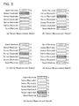
- the vertical axis indicates sensor output (V)
- the horizontal axis indicates electrode numbers assigned to the sensor electrodes 102a to 102e (for example, electrode numbers 1 to 5 were assigned to the sensor electrodes 102a to 102e in this order).
- the vertical axis indicates sensor output (V)
- the horizontal axis indicates distance of displacement (mm).
- the sensor outputs (V) of the sensor electrode 102a (electrode number 1) and sensor electrode 102e (electrode number 5) were the highest in the respective cases. That is, the outputs of the electrodes provided at the outermost positions in the direction of arrangement (the direction of side-by-side arrangement) of the sensor electrodes 102a to 102e were the highest.
- the present invention was made in view of this point, and aims for providing a capacitance-type sensor which can measure the distance between a sensing target and sensors accurately by suppressing differences in the amount of change in the outputs of the sensors and differences in the initial capacitances of the sensors, and which hence can detect the sensing target highly accurately.
- a capacitance-type sensor is a capacitance-type sensor for sensing capacitances with respect to a sensing target existing in a sensing area, and includes: a sensor electrode group including a plurality of sensor electrodes provided on a substrate; and at least one pair of guard electrodes which are formed at at least some portions of a circumference of the sensor electrode group so as to sandwich therebetween the sensor electrode group.
- the capacitance-type sensor according to the present invention can measure the distance between the sensing target and the sensors accurately by suppressing such differences in the amount of change in the outputs from the sensors and such differences in the initial capacitances of the sensors as are due to differences in the positions at which the plurality of sensor electrodes configuring the sensor electrode group are provided, and hence can detect the sensing target highly accurately.
- the plurality of sensor electrodes configuring the sensor electrode group are each driven by being supplied with a sensor potential or a guard potential equal or similar to the sensor potential, and the at least one pair of guard electrodes are driven by being supplied with the guard potential.
- the capacitance-type sensor according to the present invention further includes a detecting circuit which detects capacitance values of the sensing target based on outputs from the plurality of sensor electrodes.
- the detecting circuit includes: switching means which switches between the sensor potential and the guard potential which are to be supplied to the plurality of sensor electrodes; and detecting means which supplies the sensor potential or the guard potential to the plurality of sensor electrodes through the switching means, supplies the guard potential to the at least one pair of guard electrodes, and detects capacitance values sensed by the sensor electrodes.
- the switching means performs switching so as for the other sensor electrodes to be supplied with the guard potential.
- the plurality of sensor electrodes configuring the sensor electrode group are formed into a rectangular strip shape and provided on the substrate in a side-by-side arrangement along their shorter direction.
- the at least one pair of guard electrodes are provided at both positions that are outside the plurality of sensor electrodes in a direction of the side-by-side arrangement.
- the plurality of sensor electrodes configuring the sensor electrode group are formed into a rectangular strip shape and provided on the substrate such that some of the plurality of sensor electrodes are provided in a side-by-side arrangement along their shorter direction, and the others of the plurality of sensor electrodes are provided in a side-by-side arrangement to make their shorter direction run along a direction orthogonal to that shorter direction.
- guard electrodes there are provided at least two pairs of guard electrodes.
- One pair of guard electrodes are provided at both positions that are outside the some of the plurality of sensor electrodes in a direction of their side-by-side arrangement, and another pair of guard electrodes are provided at both positions that are outside the others of the plurality of sensor electrodes in a direction of their side-by-side arrangement.
- the detecting means may detect capacitance values from the plurality of sensor electrodes in an order from one side of the direction of the side-by-side arrangement to the other side thereof.
- the detecting means may detect capacitance values from the plurality of sensor electrodes in an order of electrode numbers assigned to the sensor electrodes.
- the detecting means may detect a surface shape of a sensing target based on capacitance values from the plurality of sensor electrodes.
- the capacitance-type sensor include: a sensor electrode group including at least three sensor electrodes provided in a side-by-side arrangement along a direction to scan the surface shape of the sensing target; and one pair of guard electrodes provided at positions that are outside the sensor electrodes in a direction of their side-by-side arrangement. It is also preferred that the sensor electrode group has the plurality of sensor electrodes provided in the side-by-side arrangement over at least 1/2 of a total length of the sensing target.
- the present invention it is possible to measure the distance between a sensing target and sensors accurately by suppressing differences in the amount of change in outputs from the sensors and differences in the initial capacitances of the sensors, and detect the sensing target highly accurately.
- Fig. 1 is an explanatory diagram for explaining an example of an electrode configuration of a capacitance-type sensor according to one embodiment of the present invention.
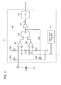
- Fig. 2 is a block diagram showing an example of a whole configuration of the capacitance-type sensor.
- Fig. 3 is a block diagram showing an example of a configuration of a sensor IC of the capacitance-type sensor.
- Fig. 4 is an operation waveform chart showing examples of operation waveforms of the sensor IC of the capacitance-type sensor.
- the capacitance-type sensor includes: a sensor electrode group 6 including a plurality of sensor electrodes 1 to 5 formed into, for example, a rectangular strip shape and provided on an unillustrated substrate in a side-by-side arrangement along their shorter direction (a direction orthogonal to the longer direction); and a pair of (a set of) guard electrodes 28a and 28b which are formed contactless from the sensor electrodes 1 to 5 of the sensor electrode group 6, being provided at at least some portions of the circumference of the sensor electrode group 6 so as to sandwich therebetween the sensor electrode group 6 (i.e., at farther outer positions than the sensor electrodes (e.g., the sensor electrodes 1 and 5) provided at the side-by-side arrangement direction outermost positions among the sensor electrodes 1 to 5 of the sensor electrode group 6).
- a sensor electrode group 6 including a plurality of sensor electrodes 1 to 5 formed into, for example, a rectangular strip shape and provided on an unillustrated substrate in a side-by-side arrangement along their shorter direction (a direction orthogonal to the
- the capacitance-type sensor senses capacitances with respect to a sensing target existing in a sensing area by means of the sensor electrodes 1 to 5 configuring the sensor electrode group 6 and provided in this way.
- the sensor electrodes 1 to 5 are each driven by being supplied with a certain sensor potential or a guard potential equal or similar to the sensor potential.
- the guard electrodes 28a and 28b are supplied with the gourd potential constantly.
- the sensor electrodes 1 to 5 and the guard electrodes 28a and 28b are formed and provided on a substrate made of, for example, a flexible printed board, a rigid substrate or a rigid flexible substrate.
- the sensor electrodes 1 to 5 and the guard electrodes 28a and 28b are made of a conductive material such as copper, copper alloy, aluminum, or the like patterned on the substrate made of an insulator such as polyethylene terephthalate (PET), polyethylene naphthalate (PEN), polyimide (PI), polyamide (PA), glass epoxy resin, or the like, or merely made of a conductive material such as an electric wire or the like laid on the substrate.
- PET polyethylene terephthalate
- PEN polyethylene naphthalate
- PI polyimide
- PA polyamide
- the sensor electrodes 1 to 5 configuring the sensor electrode group 6 are assigned, for example, electrode numbers 1 to 5 respectively. There are provided five sensor electrodes 1 to 5 here, but, for example, more than five electrodes may be provided.
- the guard electrodes 28a and 28b are provided on the same substrate as that on which the sensor electrode group 6 is provided. In this case, the guard electrodes 28a and 28b may be provided on any of the same surface as or the opposite surface to the surface on which the sensor electrode group 6 is provided.
- the guard electrodes 28a and 28b may be provided on the substrate via an insulating material.
- the sensor electrodes 1 to 5 configuring the sensor electrode group 6 are connected to a detecting circuit which detects capacitance values of a sensing target based on outputs from these sensor electrodes 1 to 5.
- the detecting circuit includes: a switching circuit 20 which switches between the sensor potential and the gourd potential which are to be supplied to the sensor electrodes 1 to 5; and a sensor IC 21 which supplies the sensor potential or the guard potential to the sensor electrodes 1 to 5 through the switching circuit 20 and detects capacitance values sensed by the sensor electrodes 1 to 5.
- the sensor IC 21 supplies the guard potential to the guard electrodes 28a and 28b constantly.
- the detecting circuit also includes an ECU (Electronic Control Unit) 22 which controls the switching circuit 20 based on outputs from the sensor IC 21 and performs various processes based on the outputs.
- the switching circuit 20 is configured by, for example, a plurality of FETs, a plurality of analog switches, or a plurality of multiplexors which are configured to enable the sensor potential and the guard potential from the sensor IC 21 to be supplied switched therebetween to each of the sensor electrodes 1 to 5.
- the switching circuit 20 switches the potential to be output from the sensor IC 21 so as for the other sensor electrodes (for example, the sensor electrodes 2 to 5) to be supplied with the guard potential.
- the sensor IC 21 detects the capacitance values from the sensor electrodes 1 to 5 of the sensor electrode group 6 by scanning the electrodes, for example, in an order from one side to the other side of the side-by-side arrangement direction (for example, in an intertemporal order from the electrode number 1 to the electrode number 5), or by scanning the electrodes in a preset order among the electrode numbers (for example, in an intertemporal order from an electrode number 1 to 3 to 5 to 2 to 4).
- the sensor IC 21 generates a pulse signal having a duty ratio which changes according to the capacitances between the sensor electrodes 1 to 5 of the sensor electrode group 6 and a sensing target (unillustrated), and smoothes the pulse signal and outputs it.
- the ECU 22 includes, for example, a CPU, a RAM, a ROM, etc., and performs various processes using the capacitance values detected by the sensor IC 21.
- the sensor IC 21 changes its duty ratio according to a capacitance C, and includes: a trigger signal generating circuit 101 which outputs a trigger signal TG having, for example, a constant period; a timer circuit 102 which outputs a pulse signal Po having a duty ratio which changes according to the level of the capacitance C connected to an input terminal; and a low-pass filter (LPF) 103 which smoothes the pulse signal Po.
- a trigger signal generating circuit 101 which outputs a trigger signal TG having, for example, a constant period
- a timer circuit 102 which outputs a pulse signal Po having a duty ratio which changes according to the level of the capacitance C connected to an input terminal
- LPF low-pass filter
- the timer circuit 102 includes: two comparators 201 and 202; an RS flip-flop (hereinafter referred to as "RS-FF" ) 203 which receives outputs of the comparators 201 and 202 at its reset terminal R and its set terminal S respectively; a buffer 204 which outputs an output DIS of the RS-FF 203 to the LPF 103; and a transistor 205 which is controlled between on and off according to the output DIS of the RS-FF 203.
- RS-FF RS flip-flop
- the comparator 202 compares such a trigger signal TG as shown in Fig. 4 which is output by the trigger signal generating circuit 101 with a certain threshold Vth2 divided by resistors R1, R2, and R3, and outputs a set pulse synchronized with the trigger signal TG.
- This set pulse sets a Q output of the RS-FF 203.
- the Q output as a discharge signal DIS turns off the transistor 205, and electrically charges between the sensor electrode 1 (2 to 5) and a ground at a speed defined by a time constant set by the to-ground capacitance C of the senor electrode 1 (2 to 5) and a resistor R4 connected between the input terminal and a power supply line. Accordingly, the potential of an input signal Vin rises at a speed defined by the capacitance C.
- the timer circuit 102 outputs a pulse signal Po which, as shown in Fig. 4 , oscillates at a duty ratio that is based on the capacitance C between the sensor electrode 1 (2 to 5) and a sensing target (unillustrated) existing in the sensing area.
- the LPF 103 outputs a direct-current signal Vout shown in Fig. 4 by smoothing the pulse signal Po. Note that in Fig. 4 , a waveform indicated by a solid line and a waveform indicated by a dotted line show that the former has a smaller capacitance than that of the latter, and, for example, the latter represents a condition that an object is coming close.
- Figs. 5 are explanatory diagrams for explaining an example of the operation of the capacitance-type sensor according to one embodiment of the present invention.
- the symbol "S" indicates the sensor potential and "G” indicates the guard potential.
- the guard potential is supplied to the other sensor electrodes 2 to 5 and the pair of guard electrodes 28a and 28b to bring a "sensor measurement state 1" as shown in Fig. 5(a) .
- the guard potential is supplied to the other sensor electrodes 1 and 3 to 5 and the pair of guard electrodes 28a and 28b to bring a "sensor measurement state 2" as shown in Fig. 5(b) .
- the guard potential is supplied to the other sensor electrodes 1, 2, 4, and 5 and the pair of guard electrodes 28a and 28b to bring a "sensor measurement state 3" as shown in Fig. 5(c) .
- the guard potential is supplied to the other sensor electrodes 1 to 3 and 5 and the pair of guard electrodes 28a and 28b to bring a "sensor measurement state 4" as shown in Fig. 5(d) .
- the guard potential is supplied to the other sensor electrodes 1 to 4 and the pair of guard electrodes 28a and 28b to bring a "sensor measurement state 5" as shown in Fig. 5(e) .
- the pair of guard electrodes 28a and 28b are driven at the guard potential constantly while the sensor electrodes 1 to 5 of the sensor electrode group 6 are activated sequentially. Therefore, even when, for example, the sensor electrode 1 or 5 provided at the outermost position among the sensor electrode group 6 is activated, it is possible to realize a state where there exist electrodes at the guard potential on both sides (side-by-side arrangement direction both sides) of the sensor electrode 1 or 5. Accordingly, it is possible to suppress electrical capacitance coupling toward the outside of the sensor electrode group 6.
- sensor output voltages of the sensor electrodes 1 to 5 of the sensor electrode group 6 turned out to be substantially uniform (i.e., the sensor sensitivities were substantially uniform), as shown in Fig. 6(a) .
- sensor output voltages of the sensors 1 to 5 of the sensor electrode group 6 turned out to be substantially uniform (i.e., the sensor sensitivities were substantially uniform), as shown in Fig. 6(a) .
- a head 49 of a human body was measured as shown in Fig. 6(b) , there occurred differences in the sensor output voltages of the sensors 1 to 5 of the sensor electrode group 6, and hence it was possible to detect the occipital shape (i.e., a non-flat shape) of the head 49 securely.
- the capacitance-type sensor can measure the distance between the sensing target and the sensor electrodes 1 to 5 accurately by suppressing differences in the amount of change in the outputs from the sensor electrodes 1 to 5 configuring the sensor electrode group 6 and differences in the initial capacitances of the sensor electrodes 1 to 5 and hence can detect the sensing target highly accurately.
- the pair of guard electrodes 28a and 28b may have the same area as that of the sensor electrodes 1 to 5 configuring the sensor electrode group 6 or a larger area than that.
- the surface shape of a sensing target for example, the occipital shape of the head 49
- a sensing target for example, the occipital shape of the head 49
- at least three sensor electrodes be provided in a side-by-side arrangement along a direction to scan the surface shape of the sensing target, and that a pair of guard electrodes be provided at both positions that are outside the sensor electrodes in their side-by-side arrangement direction.
- the sensor electrode group 6 is provided such that its sensor electrodes are provided in the side-by-side arrangement over at least 1/2 or preferably 3/4 or longer of the total length of the sensing target.
- Fig. 7 is an explanatory diagram for explaining another example of the electrode configuration of the capacitance-type sensor according to one embodiment of the present invention.
- any portions that are the same as the portions already explained will be denoted by the same reference numerals and will not be explained, and any portions that are not particularly relevant to the present invention might not be set forth.
- the capacitance-type sensor according to the present example is provided on a substrate such that some electrodes (for example, sensor electrodes 1 to 3) of the sensor electrodes 1 to 5 configuring the sensor electrode group 6 are provided in a side-by-side arrangement along their shorter direction and the others (for example, the sensor electrodes 4 and 5) are provided in a side-by-side arrangement to make their shorter direction run along a direction orthogonal to the side-by-side arrangement direction (i.e., the shorter direction) of the sensor electrodes 1 to 3 (here, in a state sandwiching therebetween the sensor electrodes 1 to 3).
- the present capacitance-type sensor includes at least two pairs of guard electrodes.
- One pair of guard electrodes 28a and 28b are provided at positions that are farther outside the sensor electrodes 1 to 3 in their side-by-side arrangement direction
- another pair of guard electrodes 28c and 28d are provided at positions that are farther outside the sensor electrode 4 and 5 in their side-by-side arrangement direction.
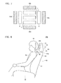
- Fig. 8 is an explanatory diagram showing an example in which the capacitance-type sensor according to one embodiment of the present invention is applied to a headrest position adjusting device for a seat
- Fig. 9 is an explanatory diagram showing a portion in a headrest extracted from the headrest position adjusting device.
- the capacitance-type sensor according to the present embodiment is configured as a sensor unit 10 and employed in the headrest position adjusting device 100.
- the headrest position adjusting device 100 is provided, for example inside a headrest 43 of a seat 40 of a vehicle, etc., and includes: a sensor unit 10 including the sensor electrodes 1 to 5 configuring the sensor electrode group 6 and the pair of guard electrodes 28a and 28b which are provided in a front portion of the headrest 43 in a side-by-side arrangement along the height direction of the headrest 43; and a drive motor unit 30 which is provided in, for example, a backrest 41 of the seat 40.
- the sensor unit 10 and the drive motor unit 30 are electrically connected through a harness 29.
- the sensor unit 10 and the drive motor unit 30 may be configured controllable wirelessly, etc.
- the sensor unit 10 includes: the sensor electrodes 1 to 5 and the guard electrodes 28a and 28b which are formed on one surface of a substrate 19; and a detecting circuit unit 27 or the like which is provided, for example, on the other surface of the substrate 19 and includes the switching circuit 20 and sensor IC 21 (unillustrated) described above.
- the sensor unit 10 senses capacitances between a head (sensing target) 49 of a human body 48 sitting on a sitting portion 42 of the seat 40 and the headrest 43 (specifically, the sensor electrodes 1 to 5 of the sensor electrode group 6).
- the sensor IC 21 of the detecting circuit unit 20 detects capacitance values based on sensing signals from the sensor electrodes 1 to 5, and outputs information regarding the detected results to the ECU 22 (unillustrated).
- the ECU 22 detects the sensor electrode having output, for example, a signal having the highest value among the sensor electrodes 1 to 5 based on the information input thereto, derives the center position (estimated center position) of the head 49 that is estimated by calculation according to the detected results, and outputs drive information for the headrest 43 according to the estimation result to the drive motor unit 30.
- the drive motor unit 30 moves a support shaft 43a by which the headrest 43 is supported on the backrest 41 in, for example, upward and downward, leftward and rightward, or frontward and rearward directions to adjust the position (for example, the height-direction center position) of the headrest 43 to an appropriate position for the head 49.
- the drive motor unit 30 adjusts the position of one detected sensor electrode to face the height-direction center position of the headrest 43 horizontally straight, adjusts the position of the sensor electrode to come above the height-direction center position of the headrest 43 by some degree, or generates profile information about the shape of the head 49 based on the detected results and adjusts the headrest 43 to an appropriate position based on the profile information.
- the headrest position adjusting device 100 having this configuration employs the sensor unit 10 including the capacitance-type sensor according to the above-described embodiment, it can detect the sensing target highly accurately and adjust the position of the headrest 43 to an appropriate position automatically. Therefore, when the seat 40 is mounted on, for example, a vehicle, the device can prevent accidents due to failure to adjust the position of the headrest 43 such as cervical spine injury in a car crash, etc.
- the capacitance-type sensor according to the embodiment described above can measure the distance between a sensing target and sensors accurately by suppressing differences in the amount of change in the outputs from the sensor electrodes 1 to 5 configuring the sensor electrode group 6 and differences in the initial capacitances of the sensor electrodes 1 to 5 and detect the sensing target highly accurately.
Landscapes
- Engineering & Computer Science (AREA)
- Mechanical Engineering (AREA)
- Physics & Mathematics (AREA)
- General Physics & Mathematics (AREA)
- Measurement Of Length, Angles, Or The Like Using Electric Or Magnetic Means (AREA)
Abstract
To measure the distance between a sensing target and sensors accurately by suppressing differences in amount of change in outputs from sensors and differences in initial capacitances thereof and detect the sensing target highly accurately, capacitance-type sensor includes: sensor electrodes 1 to 5 configuring a sensor electrode group 6; and a pair of guard electrodes 28a and 28b. The sensor electrodes 1 to 5 are driven being supplied with a sensor potential or a guard potential, and the guard electrodes 28a and 28b are driven being supplied with the guard potential. Even when the outermost sensor electrode 1 or 5 of the sensor electrode group 6 is activated, the amount of change in the outputs from the sensor electrodes 1 to 5 configuring the sensor electrode group 6 and their capacitance values can be made substantially uniform because the guard electrodes 28a and 28b are driven at the guard potential.
Description
- The present invention relates to a capacitance-type sensor which senses a capacitance with respect to a sensing target existing in a sensing area, and particularly to a capacitance-type sensor which can sense the position of the sensing target in the sensing area highly precisely.
- The followings have been conventionally known as techniques for sensing a sensing target (an object, etc.) existing in a sensing area. That is, a headrest driving device disclosed in
Patent Document 1 identified below includes: support means which supports a headrest movably; driving means which drives the headrest reciprocatingly; a plurality of detecting electrodes (sensing electrodes) which are provided inside an external cover of the headrest at a portion for supporting a head and at a distance from each other; capacitance detecting means which detects capacitances formed by these plurality of detecting electrodes with respect to a common potential line; and position controlling means which controls the driving means to drive the headrest to move in a direction to bring the capacitances into balance. - According to this headrest driving device, the headrest is driven by the driving means controlled by the position controlling means in such a way that the head comes to be located at the middle position between the plurality of detecting electrodes, in other words, in such a way that the headrest is moved in accordance with the movement of the head, whereby the position of the headrest is adjusted automatically.
- A device for adjusting a headrest disclosed in
Patent Document 2 identified below is configured by a sensor including two capacitor plates which are provided inside the headrest for sensing the position of the head of a vehicle occupant. These two capacitor plates are arranged one above the other inside the headrest. - As far as a sensor signal from one capacitor plate increases while at the same time a sensor signal from the other capacitor plate decreases, a position of the headrest in height is adjusted in such a manner as to be changed from a home position where the headrest is retracted.
- A headrest adjusting device disclosed in
Patent Document 3 identified below includes: a headrest provided above a seat back (backrest) to be movable upward and downward by being driven by a motor; a head detecting sensor which detects the position of the head of a sitting person (vehicle occupant); and a CPU which adjusts the height of the headrest to match the position of the head of the sitting person based on a signal from the head detecting sensor. - This headrest adjusting device starts the operation of adjusting the headrest when the CPU senses an electrical conduction of an ignition switch, a sitting sensor senses sitting, and a seatbelt buckle switch senses fastening of a seatbelt of the vehicle.
- An object detecting device disclosed in
Patent Document 4 identified below includes a sensor electrode unit which is formed by inserting a plurality of sensor electrodes arranged at regular intervals into a resin and insert-molding the electrodes. This sensor electrode unit is hollow, has a generally rectangular cross-sectional shape, and has the sensor electrodes provided on at least one side of the rectangle, which improves the latitude of installation while maintaining the detection performance. -
- Patent Document 1:
JPS64-11512A - Patent Document 2:
JP2000-309242A - Patent Document 3:
JPH11-180200A - Patent Document 4:
JPH11-213296A - However, the headrest driving device disclosed in
Patent Document 1 identified above adjusts the position of the headrest based on capacitances between the headrest and a ceiling portion, etc. of a vehicle. The device for adjusting a headrest disclosed inPatent Document 2 identified above measures capacitances between a head and sensing electrodes by means of two or three capacitor plates and uses the capacitances for position adjustment. - The headrest position adjusting device disclosed in
Patent Document 3 identified above performs position adjustment for the headrest according to results of adjustments of each portion of the seat. The object detecting device disclosed inPatent Document 4 identified above can sense capacitances by means of the sensor electrodes stably if, for example, the middle position among the plurality of sensor electrodes faces the exact center of a sensing target. - As can be understood, the conventional techniques have to sense an object by comparing the outputs from the sensors for balancing them or comparing the peaks of the outputs from the sensing electrodes. According to such sensing methods, the initial capacitances of the sensing electrodes (i.e., the capacitance values when no sensing target is existing) and the sensing sensitivities thereof might greatly vary depending on, for example, the positions at which the plurality of sensing electrodes are provided.
- As an example, the configuration of a sample of an experiment carried out by the applicant herein is shown in
Fig. 10 , and the results of the experiment are shown inFigs. 11 . In this experiment, as shown inFig. 10 , asensor unit 102 configured by a plurality of sensor electrodes 102a to 102e formed on asubstrate 102f was placed on abase 101 made of, for example, foamed polystyrene. Aflat panel 104 supplied with a ground (GND) potential in the direction of an outline arrow ofFig. 10 was overlaid above thesensor unit 102 with apanel member 103 interposed therebetween that had a certain thickness L and was made of foamed polystyrene. - In this state where the distance between the sensor electrodes 102a to 102e of the
sensor unit 102 and the flat panel 104 (the thickness L of the panel member 103) was constant, the outputs (V) of the sensor electrodes 102a to 102e versus the distance L between thesensor unit 102 and the flat panel 104 (seeFig. 11(a) ) and the amount of change in the outputs (V) versus change in the distance L (seeFig. 11(b) ) were measured. - In the graph of
Fig. 11(a) , the vertical axis indicates sensor output (V), and the horizontal axis indicates electrode numbers assigned to the sensor electrodes 102a to 102e (for example,electrode numbers 1 to 5 were assigned to the sensor electrodes 102a to 102e in this order). In the graph ofFig. 11(b) , the vertical axis indicates sensor output (V), and the horizontal axis indicates distance of displacement (mm). - According to the results of measurement, when the distance L between the
sensor unit 102 and theflat panel 104 was changed, for example, from 20mm to 40mm, 60 mm, and 75mm as shown inFig. 11(a) , the sensor outputs (V) of the sensor electrode 102a (electrode number 1) andsensor electrode 102e (electrode number 5) were the highest in the respective cases. That is, the outputs of the electrodes provided at the outermost positions in the direction of arrangement (the direction of side-by-side arrangement) of the sensor electrodes 102a to 102e were the highest. - When the amount of change L in the distance L was, for example, 20mm40mm, 40mm60mm, and 60mm75mm as shown in
Fig. 11(b) , changes in the capacitance value (=C) in the respective cases drew different trajectories for the different sensor electrodes 102a to 102e. Particularly, the differences of the trajectories represent differences in the amount of change in the output, and it was found that the group of dots indicating the sensor outputs of when, for example, the amount of change L was 20mm40mm fell within a range having a dispersion of about 100mV. - Hence, if such differences among the sensor electrodes 102a to 102e in the amount of change in the output are significant, it might be difficult to measure the distance between the sensing target and the
sensor unit 102 accurately by the various sensing methods described above. - The present invention was made in view of this point, and aims for providing a capacitance-type sensor which can measure the distance between a sensing target and sensors accurately by suppressing differences in the amount of change in the outputs of the sensors and differences in the initial capacitances of the sensors, and which hence can detect the sensing target highly accurately.
- A capacitance-type sensor according to the present invention is a capacitance-type sensor for sensing capacitances with respect to a sensing target existing in a sensing area, and includes: a sensor electrode group including a plurality of sensor electrodes provided on a substrate; and at least one pair of guard electrodes which are formed at at least some portions of a circumference of the sensor electrode group so as to sandwich therebetween the sensor electrode group.
- By being configured as described above, the capacitance-type sensor according to the present invention can measure the distance between the sensing target and the sensors accurately by suppressing such differences in the amount of change in the outputs from the sensors and such differences in the initial capacitances of the sensors as are due to differences in the positions at which the plurality of sensor electrodes configuring the sensor electrode group are provided, and hence can detect the sensing target highly accurately.
- For example, the plurality of sensor electrodes configuring the sensor electrode group are each driven by being supplied with a sensor potential or a guard potential equal or similar to the sensor potential, and the at least one pair of guard electrodes are driven by being supplied with the guard potential.
- Preferably, the capacitance-type sensor according to the present invention further includes a detecting circuit which detects capacitance values of the sensing target based on outputs from the plurality of sensor electrodes. For example, the detecting circuit includes: switching means which switches between the sensor potential and the guard potential which are to be supplied to the plurality of sensor electrodes; and detecting means which supplies the sensor potential or the guard potential to the plurality of sensor electrodes through the switching means, supplies the guard potential to the at least one pair of guard electrodes, and detects capacitance values sensed by the sensor electrodes.
For example, when one of the plurality of sensor electrodes configuring the sensor electrode group is supplied with the sensor potential, the switching means performs switching so as for the other sensor electrodes to be supplied with the guard potential. - For example, the plurality of sensor electrodes configuring the sensor electrode group are formed into a rectangular strip shape and provided on the substrate in a side-by-side arrangement along their shorter direction.
- In this case, for example, the at least one pair of guard electrodes are provided at both positions that are outside the plurality of sensor electrodes in a direction of the side-by-side arrangement.
- For example, the plurality of sensor electrodes configuring the sensor electrode group are formed into a rectangular strip shape and provided on the substrate such that some of the plurality of sensor electrodes are provided in a side-by-side arrangement along their shorter direction, and the others of the plurality of sensor electrodes are provided in a side-by-side arrangement to make their shorter direction run along a direction orthogonal to that shorter direction.
- In this case, for example, there are provided at least two pairs of guard electrodes. One pair of guard electrodes are provided at both positions that are outside the some of the plurality of sensor electrodes in a direction of their side-by-side arrangement, and another pair of guard electrodes are provided at both positions that are outside the others of the plurality of sensor electrodes in a direction of their side-by-side arrangement.
- For example, the detecting means may detect capacitance values from the plurality of sensor electrodes in an order from one side of the direction of the side-by-side arrangement to the other side thereof.
- For example, the detecting means may detect capacitance values from the plurality of sensor electrodes in an order of electrode numbers assigned to the sensor electrodes.
- The detecting means may detect a surface shape of a sensing target based on capacitance values from the plurality of sensor electrodes.
In this case, it is preferred that the capacitance-type sensor include: a sensor electrode group including at least three sensor electrodes provided in a side-by-side arrangement along a direction to scan the surface shape of the sensing target; and one pair of guard electrodes provided at positions that are outside the sensor electrodes in a direction of their side-by-side arrangement.
It is also preferred that the sensor electrode group has the plurality of sensor electrodes provided in the side-by-side arrangement over at least 1/2 of a total length of the sensing target. - According to the present invention, it is possible to measure the distance between a sensing target and sensors accurately by suppressing differences in the amount of change in outputs from the sensors and differences in the initial capacitances of the sensors, and detect the sensing target highly accurately.
- A preferred embodiment of a capacitance-type sensor according to the present invention will be explained below in detail with reference to the attached drawings.
-
Fig. 1 is an explanatory diagram for explaining an example of an electrode configuration of a capacitance-type sensor according to one embodiment of the present invention.Fig. 2 is a block diagram showing an example of a whole configuration of the capacitance-type sensor.Fig. 3 is a block diagram showing an example of a configuration of a sensor IC of the capacitance-type sensor.Fig. 4 is an operation waveform chart showing examples of operation waveforms of the sensor IC of the capacitance-type sensor. - As shown in
Fig. 1 , the capacitance-type sensor according to one embodiment of the present invention includes: asensor electrode group 6 including a plurality ofsensor electrodes 1 to 5 formed into, for example, a rectangular strip shape and provided on an unillustrated substrate in a side-by-side arrangement along their shorter direction (a direction orthogonal to the longer direction); and a pair of (a set of)guard electrodes sensor electrodes 1 to 5 of thesensor electrode group 6, being provided at at least some portions of the circumference of thesensor electrode group 6 so as to sandwich therebetween the sensor electrode group 6 (i.e., at farther outer positions than the sensor electrodes (e.g., thesensor electrodes 1 and 5) provided at the side-by-side arrangement direction outermost positions among thesensor electrodes 1 to 5 of the sensor electrode group 6). - The capacitance-type sensor senses capacitances with respect to a sensing target existing in a sensing area by means of the
sensor electrodes 1 to 5 configuring thesensor electrode group 6 and provided in this way. Thesensor electrodes 1 to 5 are each driven by being supplied with a certain sensor potential or a guard potential equal or similar to the sensor potential. Theguard electrodes - The
sensor electrodes 1 to 5 and theguard electrodes sensor electrodes 1 to 5 and theguard electrodes - The
sensor electrodes 1 to 5 configuring thesensor electrode group 6 are assigned, for example,electrode numbers 1 to 5 respectively. There are provided fivesensor electrodes 1 to 5 here, but, for example, more than five electrodes may be provided.
Theguard electrodes sensor electrode group 6 is provided. In this case, theguard electrodes sensor electrode group 6 is provided. Theguard electrodes - As shown in
Fig. 2 , thesensor electrodes 1 to 5 configuring thesensor electrode group 6 are connected to a detecting circuit which detects capacitance values of a sensing target based on outputs from thesesensor electrodes 1 to 5. The detecting circuit includes: a switchingcircuit 20 which switches between the sensor potential and the gourd potential which are to be supplied to thesensor electrodes 1 to 5; and asensor IC 21 which supplies the sensor potential or the guard potential to thesensor electrodes 1 to 5 through the switchingcircuit 20 and detects capacitance values sensed by thesensor electrodes 1 to 5. Thesensor IC 21 supplies the guard potential to theguard electrodes - The detecting circuit also includes an ECU (Electronic Control Unit) 22 which controls the switching
circuit 20 based on outputs from thesensor IC 21 and performs various processes based on the outputs. The switchingcircuit 20 is configured by, for example, a plurality of FETs, a plurality of analog switches, or a plurality of multiplexors which are configured to enable the sensor potential and the guard potential from thesensor IC 21 to be supplied switched therebetween to each of thesensor electrodes 1 to 5. - For example, when one sensor electrode (for example, the sensor electrode 1) of the
sensor electrodes 1 to 5 configuring thesensor electrode group 6 is supplied with the sensor potential, the switchingcircuit 20 switches the potential to be output from thesensor IC 21 so as for the other sensor electrodes (for example, thesensor electrodes 2 to 5) to be supplied with the guard potential. - The
sensor IC 21 detects the capacitance values from thesensor electrodes 1 to 5 of thesensor electrode group 6 by scanning the electrodes, for example, in an order from one side to the other side of the side-by-side arrangement direction (for example, in an intertemporal order from theelectrode number 1 to the electrode number 5), or by scanning the electrodes in a preset order among the electrode numbers (for example, in an intertemporal order from anelectrode number 1 to 3 to 5 to 2 to 4). - For example, the
sensor IC 21 generates a pulse signal having a duty ratio which changes according to the capacitances between thesensor electrodes 1 to 5 of thesensor electrode group 6 and a sensing target (unillustrated), and smoothes the pulse signal and outputs it. TheECU 22 includes, for example, a CPU, a RAM, a ROM, etc., and performs various processes using the capacitance values detected by thesensor IC 21. - As shown in
Fig. 3 , thesensor IC 21 changes its duty ratio according to a capacitance C, and includes: a triggersignal generating circuit 101 which outputs a trigger signal TG having, for example, a constant period; atimer circuit 102 which outputs a pulse signal Po having a duty ratio which changes according to the level of the capacitance C connected to an input terminal; and a low-pass filter (LPF) 103 which smoothes the pulse signal Po. - For example, the
timer circuit 102 includes: twocomparators comparators buffer 204 which outputs an output DIS of the RS-FF 203 to theLPF 103; and atransistor 205 which is controlled between on and off according to the output DIS of the RS-FF 203. - The
comparator 202 compares such a trigger signal TG as shown inFig. 4 which is output by the triggersignal generating circuit 101 with a certain threshold Vth2 divided by resistors R1, R2, and R3, and outputs a set pulse synchronized with the trigger signal TG. This set pulse sets a Q output of the RS-FF 203. - The Q output as a discharge signal DIS turns off the
transistor 205, and electrically charges between the sensor electrode 1 (2 to 5) and a ground at a speed defined by a time constant set by the to-ground capacitance C of the senor electrode 1 (2 to 5) and a resistor R4 connected between the input terminal and a power supply line. Accordingly, the potential of an input signal Vin rises at a speed defined by the capacitance C. - When the input signal Vin exceeds a threshold Vth1 defined by the resistors R1, R2, and R3, the output of the
comparator 201 is inverted, thereby inverting the output of the RS-FF 203. As a result, thetransistor 205 is turned on, and the charges accumulated in the sensor electrode 1 (2 to 5) are discharged through thetransistor 205. - Hence, the
timer circuit 102 outputs a pulse signal Po which, as shown inFig. 4 , oscillates at a duty ratio that is based on the capacitance C between the sensor electrode 1 (2 to 5) and a sensing target (unillustrated) existing in the sensing area. TheLPF 103 outputs a direct-current signal Vout shown inFig. 4 by smoothing the pulse signal Po. Note that inFig. 4 , a waveform indicated by a solid line and a waveform indicated by a dotted line show that the former has a smaller capacitance than that of the latter, and, for example, the latter represents a condition that an object is coming close. - Specifically, the capacitance-type sensor having such a configuration senses the capacitance C with respect to a sensing target by the following operation.
Figs. 5 are explanatory diagrams for explaining an example of the operation of the capacitance-type sensor according to one embodiment of the present invention. InFigs. 5 , the symbol "S" indicates the sensor potential and "G" indicates the guard potential. - First, when the
sensor electrode 1 of thesensor electrode group 6 is activated by the switchingcircuit 20 under the control of theECU 22, the guard potential is supplied to theother sensor electrodes 2 to 5 and the pair ofguard electrodes sensor measurement state 1" as shown inFig. 5(a) . - Next, when the
sensor electrode 2 of thesensor electrode group 6 is activated, the guard potential is supplied to theother sensor electrodes guard electrodes sensor measurement state 2" as shown inFig. 5(b) . Then, when thesensor electrode 3 of thesensor electrode group 6 is activated, the guard potential is supplied to theother sensor electrodes guard electrodes sensor measurement state 3" as shown inFig. 5(c) . - When the
sensor electrode 4 of thesensor electrode group 6 is activated, the guard potential is supplied to theother sensor electrodes 1 to 3 and 5 and the pair ofguard electrodes sensor measurement state 4" as shown inFig. 5(d) . Likewise, when thesensor electrode 5 of thesensor electrode group 6 is activated, the guard potential is supplied to theother sensor electrodes 1 to 4 and the pair ofguard electrodes sensor measurement state 5" as shown inFig. 5(e) . - In this way, the pair of
guard electrodes sensor electrodes 1 to 5 of thesensor electrode group 6 are activated sequentially. Therefore, even when, for example, thesensor electrode sensor electrode group 6 is activated, it is possible to realize a state where there exist electrodes at the guard potential on both sides (side-by-side arrangement direction both sides) of thesensor electrode sensor electrode group 6. - That is, when measurements were carried out on the same condition as that explained above with reference to
Fig. 10 andFigs. 11 , sensor output voltages of thesensor electrodes 1 to 5 of thesensor electrode group 6 turned out to be substantially uniform (i.e., the sensor sensitivities were substantially uniform), as shown inFig. 6(a) . Moreover, when ahead 49 of a human body was measured as shown inFig. 6(b) , there occurred differences in the sensor output voltages of thesensors 1 to 5 of thesensor electrode group 6, and hence it was possible to detect the occipital shape (i.e., a non-flat shape) of thehead 49 securely. - Hence, the capacitance-type sensor according to the present embodiment can measure the distance between the sensing target and the
sensor electrodes 1 to 5 accurately by suppressing differences in the amount of change in the outputs from thesensor electrodes 1 to 5 configuring thesensor electrode group 6 and differences in the initial capacitances of thesensor electrodes 1 to 5 and hence can detect the sensing target highly accurately. The pair ofguard electrodes sensor electrodes 1 to 5 configuring thesensor electrode group 6 or a larger area than that. - When detecting the surface shape of a sensing target (for example, the occipital shape of the head 49) based on capacitance values from a plurality of sensor electrodes as described above, it is preferable that at least three sensor electrodes be provided in a side-by-side arrangement along a direction to scan the surface shape of the sensing target, and that a pair of guard electrodes be provided at both positions that are outside the sensor electrodes in their side-by-side arrangement direction. The
sensor electrode group 6 is provided such that its sensor electrodes are provided in the side-by-side arrangement over at least 1/2 or preferably 3/4 or longer of the total length of the sensing target. -
Fig. 7 is an explanatory diagram for explaining another example of the electrode configuration of the capacitance-type sensor according to one embodiment of the present invention. In the following description, any portions that are the same as the portions already explained will be denoted by the same reference numerals and will not be explained, and any portions that are not particularly relevant to the present invention might not be set forth. - As shown in
Fig. 7 , the capacitance-type sensor according to the present example is provided on a substrate such that some electrodes (for example,sensor electrodes 1 to 3) of thesensor electrodes 1 to 5 configuring thesensor electrode group 6 are provided in a side-by-side arrangement along their shorter direction and the others (for example, thesensor electrodes 4 and 5) are provided in a side-by-side arrangement to make their shorter direction run along a direction orthogonal to the side-by-side arrangement direction (i.e., the shorter direction) of thesensor electrodes 1 to 3 (here, in a state sandwiching therebetween thesensor electrodes 1 to 3). - The present capacitance-type sensor includes at least two pairs of guard electrodes. One pair of
guard electrodes sensor electrodes 1 to 3 in their side-by-side arrangement direction, and another pair ofguard electrodes sensor electrode sensor electrode group 6, it becomes possible to detect outputs of not only the side-by-side arrangement direction of thesensor electrodes 1 to 3 but also the side-by-side arrangement direction of thesensor electrodes -
Fig. 8 is an explanatory diagram showing an example in which the capacitance-type sensor according to one embodiment of the present invention is applied to a headrest position adjusting device for a seat, andFig. 9 is an explanatory diagram showing a portion in a headrest extracted from the headrest position adjusting device. As shown inFig. 8 andFig. 9 , the capacitance-type sensor according to the present embodiment is configured as asensor unit 10 and employed in the headrestposition adjusting device 100. - The headrest
position adjusting device 100 is provided, for example inside aheadrest 43 of aseat 40 of a vehicle, etc., and includes: asensor unit 10 including thesensor electrodes 1 to 5 configuring thesensor electrode group 6 and the pair ofguard electrodes headrest 43 in a side-by-side arrangement along the height direction of theheadrest 43; and adrive motor unit 30 which is provided in, for example, abackrest 41 of theseat 40. - Here, the
sensor unit 10 and thedrive motor unit 30 are electrically connected through aharness 29. Thesensor unit 10 and thedrive motor unit 30 may be configured controllable wirelessly, etc. - The
sensor unit 10 includes: thesensor electrodes 1 to 5 and theguard electrodes substrate 19; and a detectingcircuit unit 27 or the like which is provided, for example, on the other surface of thesubstrate 19 and includes the switchingcircuit 20 and sensor IC 21 (unillustrated) described above. Thesensor unit 10 senses capacitances between a head (sensing target) 49 of ahuman body 48 sitting on a sittingportion 42 of theseat 40 and the headrest 43 (specifically, thesensor electrodes 1 to 5 of the sensor electrode group 6). - The
sensor IC 21 of the detectingcircuit unit 20 detects capacitance values based on sensing signals from thesensor electrodes 1 to 5, and outputs information regarding the detected results to the ECU 22 (unillustrated). TheECU 22 detects the sensor electrode having output, for example, a signal having the highest value among thesensor electrodes 1 to 5 based on the information input thereto, derives the center position (estimated center position) of thehead 49 that is estimated by calculation according to the detected results, and outputs drive information for theheadrest 43 according to the estimation result to thedrive motor unit 30. - In response to the output from the
ECU 22, thedrive motor unit 30 moves asupport shaft 43a by which theheadrest 43 is supported on thebackrest 41 in, for example, upward and downward, leftward and rightward, or frontward and rearward directions to adjust the position (for example, the height-direction center position) of theheadrest 43 to an appropriate position for thehead 49. Specifically, for example, thedrive motor unit 30 adjusts the position of one detected sensor electrode to face the height-direction center position of theheadrest 43 horizontally straight, adjusts the position of the sensor electrode to come above the height-direction center position of theheadrest 43 by some degree, or generates profile information about the shape of thehead 49 based on the detected results and adjusts theheadrest 43 to an appropriate position based on the profile information. - Since the headrest
position adjusting device 100 having this configuration employs thesensor unit 10 including the capacitance-type sensor according to the above-described embodiment, it can detect the sensing target highly accurately and adjust the position of theheadrest 43 to an appropriate position automatically. Therefore, when theseat 40 is mounted on, for example, a vehicle, the device can prevent accidents due to failure to adjust the position of theheadrest 43 such as cervical spine injury in a car crash, etc. - As described above, the capacitance-type sensor according to the embodiment described above can measure the distance between a sensing target and sensors accurately by suppressing differences in the amount of change in the outputs from the
sensor electrodes 1 to 5 configuring thesensor electrode group 6 and differences in the initial capacitances of thesensor electrodes 1 to 5 and detect the sensing target highly accurately. -
- [
Fig.1] Fig. 1 is an explanatory diagram for explaining an example of an electrode configuration of a capacitance-type sensor according to one embodiment of the present invention. - [
Fig. 2] Fig. 2 is a block diagram showing an example of a whole configuration of the capacitance-type sensor. - [
Fig. 3] Fig. 3 is a block diagram showing an example of a configuration of a sensor IC of the capacitance-type sensor. - [
Fig. 4] Fig. 4 is an operation waveform chart showing examples of operation waveforms of the sensor IC of the capacitance-type sensor. - [
Figs. 5] Figs. 5 are explanatory diagrams for explaining an example of an operation of the capacitance-type sensor according to one embodiment of the present invention. - [
Figs. 6] Figs. 6 are explanatory diagrams showing measurement results of the capacitance-type sensor according to one embodiment of the present invention. - [
Fig. 7] Fig. 7 is an explanatory diagram for explaining another example of the electrode configuration of the capacitance-type sensor according to one embodiment of the present invention. - [
Fig. 8] Fig. 8 is an explanatory diagram showing an example in which the capacitance-type sensor according to one embodiment of the present invention is applied to a headrest position adjusting device for a seat. - [
Fig. 9] Fig. 9 is an explanatory diagram showing a portion in a headrest extracted from the headrest position adjusting device. - [
Fig. 10] Fig. 10 is a diagram showing a configuration of a sample of an experiment carried out by the applicant. - [
Figs. 11] Figs. 11 are diagrams showing experimental results of the experiment carried out by the applicant. -
- 1 to 5
- sensor electrode
- 6
- sensor electrode group
- 10
- sensor unit
- 20
- switching circuit
- 21
- sensorIC
- 22
- ECU
- 27
- detecting circuit unit
- 28a, 28b, 28c, 28d
- guard electrode
- 29
- harness
- 30
- drive motor unit
- 40
- seat
- 41
- backrest
- 42
- sitting portion
- 43
- headrest
- 43a
- support shaft
- 48
- human body
- 49
- head
- 100
- headrest position adjusting device
Claims (13)
- A capacitance-type sensor for sensing capacitances with respect to a sensing target existing in a sensing area, comprising:a sensor electrode group including a plurality of sensor electrodes provided on a substrate; andat least one pair of guard electrodes which are formed at at least some portions of a circumference of the sensor electrode group so as to sandwich therebetween the sensor electrode group.
- The capacitance-type sensor according to claim 1,
wherein the plurality of sensor electrodes configuring the sensor electrode group are each driven by being supplied with a sensor potential or a guard potential equal or similar to the sensor potential, and the at least one pair of guard electrodes are driven by being supplied with the guard potential. - The capacitance-type sensor according to claim 2, further comprising a detecting circuit which detects capacitance values of the sensing target based on outputs from the plurality of sensor electrodes,
wherein the detecting circuit includes: switching means which switches between the sensor potential and the guard potential which are to be supplied to the plurality of sensor electrodes; and detecting means which supplies the sensor potential or the guard potential to the plurality of sensor electrodes through the switching means, supplies the guard potential to the at least one pair of guard electrodes, and detects capacitance values sensed by the sensor electrodes. - The capacitance-type sensor according to claim 3,
wherein when one of the plurality of sensor electrodes configuring the sensor electrode group is supplied with the sensor potential, the switching means performs switching so as for the other sensor electrodes to be supplied with the guard potential. - The capacitance-type sensor according to any one of claims 1 to 4,
wherein the plurality of sensor electrodes configuring the sensor electrode group are formed into a rectangular strip shape and provided on the substrate in a side-by-side arrangement along their shorter direction. - The capacitance-type sensor according to claim 5,
wherein the at least one pair of guard electrodes are provided at both positions that are outside the plurality of sensor electrodes in a direction of the side-by-side arrangement. - The capacitance-type sensor according to any one of claims 1 to 4,
wherein the plurality of sensor electrodes configuring the sensor electrode group are formed into a rectangular strip shape and provided on the substrate such that some of the plurality of sensor electrodes are provided in a side-by-side arrangement along their shorter direction, and the others of the plurality of sensor electrodes are provided in a side-by-side arrangement to make their shorter direction run along a direction orthogonal to that shorter direction. - The capacitance-type sensor according to claim 7,
wherein there are provided at least two pairs of guard electrodes, one pair of guard electrodes being provided at both positions that are outside the some of the plurality of sensor electrodes in a direction of their side-by-side arrangement, and another pair of guard electrodes being provided at both positions that are outside the others of the plurality of sensor electrodes in a direction of their side-by-side arrangement. - The capacitance-type sensor according to any one of claims 3 to 6,
wherein the detecting means detects capacitance values from the plurality of sensor electrodes in an order from one side of a direction of the side-by-side arrangement to the other side thereof. - The capacitance-type sensor according to claims 3 to 7,
wherein the detecting means detects capacitance values from the plurality of sensor electrodes in an order of electrode numbers assigned to the sensor electrodes. - The capacitance-type sensor according to claims 3 to 10,
wherein the detecting means detects a surface shape of a sensing target based on capacitance values from the plurality of sensor electrodes. - The capacitance-type sensor according to claim 11, comprising:a sensor electrode group including at least three sensor electrodes provided in a side-by-side arrangement along a direction to scan the surface shape of the sensing target; andone pair of guard electrodes provided at both positions that are outside the sensor electrodes in a direction of their side-by-side arrangement.
- The capacitance-type sensor according to claim 11 or 12,
wherein the sensor electrode group has the plurality of sensor electrodes provided in the side-by-side arrangement over at least 1/2 of a total length of the sensing target.
Applications Claiming Priority (2)
| Application Number | Priority Date | Filing Date | Title |
|---|---|---|---|
| JP2008281673 | 2008-10-31 | ||
| PCT/JP2009/068762 WO2010050607A1 (en) | 2008-10-31 | 2009-11-02 | Capacitance-type sensor |
Publications (1)
| Publication Number | Publication Date |
|---|---|
| EP2362178A1 true EP2362178A1 (en) | 2011-08-31 |
Family
ID=42128966
Family Applications (1)
| Application Number | Title | Priority Date | Filing Date |
|---|---|---|---|
| EP09823717A Withdrawn EP2362178A1 (en) | 2008-10-31 | 2009-11-02 | Capacitance-type sensor |
Country Status (6)
| Country | Link |
|---|---|
| US (1) | US20110254572A1 (en) |
| EP (1) | EP2362178A1 (en) |
| JP (1) | JPWO2010050607A1 (en) |
| KR (1) | KR20110089858A (en) |
| CN (1) | CN102203547A (en) |
| WO (1) | WO2010050607A1 (en) |
Families Citing this family (11)
| Publication number | Priority date | Publication date | Assignee | Title |
|---|---|---|---|---|
| KR20100058604A (en) * | 2007-08-28 | 2010-06-03 | 가부시키가이샤후지쿠라 | Headrest position adjusting device, and headrest position adjusting method |
| KR20120093965A (en) * | 2009-10-19 | 2012-08-23 | 가부시키가이샤후지쿠라 | Head rest position adjustment device |
| DE102010028719A1 (en) * | 2010-05-07 | 2011-11-10 | Robert Bosch Gmbh | detector |
| JP5353991B2 (en) * | 2010-11-30 | 2013-11-27 | 株式会社日本自動車部品総合研究所 | Capacitive occupant detection device |
| DE102011121775B3 (en) | 2011-12-21 | 2013-01-31 | Brose Fahrzeugteile Gmbh & Co. Kg, Hallstadt | Control system for controlling e.g. motorized side door of motor car, has distance sensors with dummy portions such that sensors comprise no sensitivity or smaller sensitivity compared to region of each sensor adjacent to dummy portions |
| JP6482760B2 (en) * | 2014-02-07 | 2019-03-13 | 株式会社フジクラ | Capacitance sensor, steering and steering system |
| DE102015119701A1 (en) * | 2015-11-15 | 2017-05-18 | Brose Fahrzeugteile Gmbh & Co. Kommanditgesellschaft, Bamberg | Method for operating a capacitive sensor arrangement of a motor vehicle |
| CN105823411B (en) * | 2016-03-18 | 2019-02-22 | 苏州椒图电子有限公司 | A kind of curved surface profile measurement method |
| KR102098693B1 (en) * | 2018-01-12 | 2020-04-08 | 주식회사 지티에스엠 | Wafer-type gapping detection sensor for sensing gapping of the wafer in chamber |
| GB2580164A (en) * | 2018-12-21 | 2020-07-15 | Imperial College Sci Tech & Medicine | A sensor |
| CN114543644B (en) * | 2022-02-18 | 2022-11-15 | 广州市欧智智能科技有限公司 | Head position detection method, device, terminal and medium |
Family Cites Families (28)
| Publication number | Priority date | Publication date | Assignee | Title |
|---|---|---|---|---|
| JPS5317071B2 (en) * | 1972-09-29 | 1978-06-06 | ||
| JPS5146152A (en) * | 1974-10-18 | 1976-04-20 | Osaka Seimitsu Kikai Kk | KEIJOSOKUTEIKI |
| US4182981A (en) * | 1977-12-08 | 1980-01-08 | Westinghouse Electric Corp. | Apparatus for gauging the shape of a conducting surface |
| JPS5914007U (en) * | 1982-07-20 | 1984-01-27 | イ−グル工業株式会社 | surface roughness meter |
| JPS59230103A (en) * | 1983-06-10 | 1984-12-24 | Inoue Japax Res Inc | Surface roughness meter |
| JPS6022603A (en) * | 1983-07-18 | 1985-02-05 | Mitsubishi Electric Corp | Control device for display |
| JPS6022602A (en) * | 1983-07-18 | 1985-02-05 | Mitsubishi Electric Corp | Control device for recorder |
| JPS6162812A (en) * | 1984-09-05 | 1986-03-31 | Kawasaki Steel Corp | Method for detecting shape of metal strip |
| JPS6411512A (en) | 1987-07-06 | 1989-01-17 | Aisin Seiki | Headrest driving apparatus |
| JPH01285801A (en) * | 1988-05-12 | 1989-11-16 | Koko Res Kk | Proximity distance sensor and discriminating apparatus of shape |
| DE4119244A1 (en) * | 1991-06-11 | 1992-12-17 | Weidmueller Interface | Capacitive sensor arrangement for measuring tool workpiece separation - contains sensor head with several electrodes on single or parallel, straight or circular lines |
| CH689190A5 (en) * | 1993-10-19 | 1998-11-30 | Hans Ulrich Meyer | Instrument for measuring lengths or angles. |
| NO304766B1 (en) * | 1997-06-16 | 1999-02-08 | Sintef | fingerprint Sensor |
| JPH11180200A (en) | 1997-12-24 | 1999-07-06 | Aisin Seiki Co Ltd | Head rest adjusting device |
| JPH11213296A (en) | 1998-01-28 | 1999-08-06 | Aisin Seiki Co Ltd | Object detector for vehicle |
| JP3347069B2 (en) * | 1998-08-31 | 2002-11-20 | 日本電気株式会社 | Occupant detection system |
| JP2000229075A (en) * | 1999-02-10 | 2000-08-22 | Toshiba Tec Corp | Finger recess/projection information input device and individual certifying device using this device |
| DE19916804C1 (en) | 1999-04-14 | 2000-08-10 | Bayerische Motoren Werke Ag | Headrest adjustment device for vehicle passenger seat uses sensor incorporated in headrest using 2 capacitor plates positioned so that head of passenger acts as capacitor dielectric |
| JP2001017412A (en) * | 1999-07-12 | 2001-01-23 | Toshiba Tec Corp | Individual authentication device |
| JP4198306B2 (en) * | 1999-07-22 | 2008-12-17 | 東京エレクトロン株式会社 | Capacitive sensor, semiconductor manufacturing apparatus, and liquid crystal display element manufacturing apparatus |
| JP2001249001A (en) * | 2000-03-03 | 2001-09-14 | Mitsutoyo Corp | Capacitance type displacement detector |
| US6552667B1 (en) * | 2000-11-16 | 2003-04-22 | Hydro-Quebec | Non-contact measuring method and apparatus for producing a signal representative of a distance between facing surfaces |
| JP3999466B2 (en) * | 2001-01-29 | 2007-10-31 | 本田技研工業株式会社 | Occupant detection device |
| JP4531469B2 (en) * | 2004-07-15 | 2010-08-25 | 株式会社フジクラ | Capacitive proximity sensor |
| US7332915B2 (en) * | 2004-09-28 | 2008-02-19 | General Electric Company | Sensor system and method of operating the same |
| JP4319970B2 (en) * | 2004-11-22 | 2009-08-26 | 株式会社フジクラ | Capacitive proximity sensor |
| US7395717B2 (en) * | 2006-02-10 | 2008-07-08 | Milliken & Company | Flexible capacitive sensor |
| DE602006010671D1 (en) * | 2006-05-17 | 2010-01-07 | Hitachi Comp Products Europ S | Method for determining the morphology of an occupant in a vehicle seat with capacitive sensors |
-
2009
- 2009-11-02 JP JP2010535860A patent/JPWO2010050607A1/en active Pending
- 2009-11-02 CN CN2009801435277A patent/CN102203547A/en active Pending
- 2009-11-02 KR KR1020117012265A patent/KR20110089858A/en active IP Right Grant
- 2009-11-02 WO PCT/JP2009/068762 patent/WO2010050607A1/en active Application Filing
- 2009-11-02 EP EP09823717A patent/EP2362178A1/en not_active Withdrawn
-
2011
- 2011-04-29 US US13/097,955 patent/US20110254572A1/en not_active Abandoned
Non-Patent Citations (1)
| Title |
|---|
| See references of WO2010050607A1 * |
Also Published As
| Publication number | Publication date |
|---|---|
| CN102203547A (en) | 2011-09-28 |
| US20110254572A1 (en) | 2011-10-20 |
| WO2010050607A1 (en) | 2010-05-06 |
| KR20110089858A (en) | 2011-08-09 |
| JPWO2010050607A1 (en) | 2012-03-29 |
Similar Documents
| Publication | Publication Date | Title |
|---|---|---|
| EP2362178A1 (en) | Capacitance-type sensor | |
| EP2141047B1 (en) | Head rest position adjusting apparatus and head rest position adjusting method | |
| US8690252B2 (en) | Headrest position adjusting device and headrest position adjusting method | |
| EP2186674B1 (en) | Headrest position adjustment device and headrest position adjustment method | |
| US20110264332A1 (en) | Headrest position adjustment device and headrest position adjustment method | |
| US8878553B2 (en) | Device for measuring distance between headrest and head, method for measuring distance between headrest and head, headrest position adjusting device, and headrest position adjusting method | |
| EP2186675B1 (en) | Headrest position adjusting device, and headrest position adjusting method | |
| EP2413091A1 (en) | Device for measuring distance between headrest and head, method for measuring distance between headrest and head, headrest position adjusting device, and headrest position adjusting method | |
| JP4588738B2 (en) | Headrest position adjusting device and position adjusting method | |
| JP5086113B2 (en) | Capacitive sensor | |
| JP5339267B2 (en) | Headrest position adjustment device and headrest position adjustment method | |
| JP5309392B2 (en) | Headrest position adjustment device | |
| JP5228206B2 (en) | Headrest position adjustment device and headrest position adjustment method |
Legal Events
| Date | Code | Title | Description |
|---|---|---|---|
| PUAI | Public reference made under article 153(3) epc to a published international application that has entered the european phase |
Free format text: ORIGINAL CODE: 0009012 |
|
| 17P | Request for examination filed |
Effective date: 20110526 |
|
| AK | Designated contracting states |
Kind code of ref document: A1 Designated state(s): AT BE BG CH CY CZ DE DK EE ES FI FR GB GR HR HU IE IS IT LI LT LU LV MC MK MT NL NO PL PT RO SE SI SK SM TR |
|
| DAX | Request for extension of the european patent (deleted) | ||
| STAA | Information on the status of an ep patent application or granted ep patent |
Free format text: STATUS: THE APPLICATION HAS BEEN WITHDRAWN |
|
| 18W | Application withdrawn |
Effective date: 20130902 |