EP2361995B2 - Pearlite rail - Google Patents
Pearlite rail Download PDFInfo
- Publication number
- EP2361995B2 EP2361995B2 EP10809927.6A EP10809927A EP2361995B2 EP 2361995 B2 EP2361995 B2 EP 2361995B2 EP 10809927 A EP10809927 A EP 10809927A EP 2361995 B2 EP2361995 B2 EP 2361995B2
- Authority
- EP
- European Patent Office
- Prior art keywords
- rail
- pearlite
- fatigue
- hardness
- surface roughness
- Prior art date
- Legal status (The legal status is an assumption and is not a legal conclusion. Google has not performed a legal analysis and makes no representation as to the accuracy of the status listed.)
- Active
Links
- 229910001562 pearlite Inorganic materials 0.000 title claims description 312
- 230000003746 surface roughness Effects 0.000 claims description 107
- 235000019592 roughness Nutrition 0.000 claims description 21
- 239000012535 impurity Substances 0.000 claims description 2
- 235000019589 hardness Nutrition 0.000 description 128
- 229910000831 Steel Inorganic materials 0.000 description 90
- 239000010959 steel Substances 0.000 description 90
- 238000010438 heat treatment Methods 0.000 description 53
- 238000005098 hot rolling Methods 0.000 description 50
- 230000000694 effects Effects 0.000 description 29
- XLYOFNOQVPJJNP-UHFFFAOYSA-N water Substances O XLYOFNOQVPJJNP-UHFFFAOYSA-N 0.000 description 25
- 230000001965 increasing effect Effects 0.000 description 22
- 229910000734 martensite Inorganic materials 0.000 description 22
- 229910000859 α-Fe Inorganic materials 0.000 description 22
- 230000002708 enhancing effect Effects 0.000 description 20
- KSOKAHYVTMZFBJ-UHFFFAOYSA-N iron;methane Chemical compound C.[Fe].[Fe].[Fe] KSOKAHYVTMZFBJ-UHFFFAOYSA-N 0.000 description 19
- 229910001566 austenite Inorganic materials 0.000 description 18
- 230000009466 transformation Effects 0.000 description 18
- 238000009661 fatigue test Methods 0.000 description 14
- 150000004767 nitrides Chemical class 0.000 description 14
- 239000012298 atmosphere Substances 0.000 description 13
- 238000001816 cooling Methods 0.000 description 13
- 239000010949 copper Substances 0.000 description 13
- 239000000463 material Substances 0.000 description 12
- 238000000034 method Methods 0.000 description 12
- 239000000126 substance Substances 0.000 description 12
- 238000003466 welding Methods 0.000 description 12
- 238000005259 measurement Methods 0.000 description 11
- 238000005096 rolling process Methods 0.000 description 11
- 229910052799 carbon Inorganic materials 0.000 description 10
- 238000002347 injection Methods 0.000 description 10
- 239000007924 injection Substances 0.000 description 10
- 238000000605 extraction Methods 0.000 description 9
- 238000012360 testing method Methods 0.000 description 9
- IJGRMHOSHXDMSA-UHFFFAOYSA-N Atomic nitrogen Chemical compound N#N IJGRMHOSHXDMSA-UHFFFAOYSA-N 0.000 description 8
- OKTJSMMVPCPJKN-UHFFFAOYSA-N Carbon Chemical compound [C] OKTJSMMVPCPJKN-UHFFFAOYSA-N 0.000 description 8
- 229910001567 cementite Inorganic materials 0.000 description 7
- 238000004881 precipitation hardening Methods 0.000 description 7
- 229910052720 vanadium Inorganic materials 0.000 description 7
- 238000009826 distribution Methods 0.000 description 6
- XEEYBQQBJWHFJM-UHFFFAOYSA-N iron Substances [Fe] XEEYBQQBJWHFJM-UHFFFAOYSA-N 0.000 description 6
- 229910052758 niobium Inorganic materials 0.000 description 6
- 229910052757 nitrogen Inorganic materials 0.000 description 6
- 239000002244 precipitate Substances 0.000 description 6
- 230000002596 correlated effect Effects 0.000 description 5
- 238000004519 manufacturing process Methods 0.000 description 5
- 238000005204 segregation Methods 0.000 description 5
- MCMNRKCIXSYSNV-UHFFFAOYSA-N Zirconium dioxide Chemical compound O=[Zr]=O MCMNRKCIXSYSNV-UHFFFAOYSA-N 0.000 description 4
- 239000012634 fragment Substances 0.000 description 4
- 238000000691 measurement method Methods 0.000 description 4
- 239000000203 mixture Substances 0.000 description 4
- 229910052782 aluminium Inorganic materials 0.000 description 3
- PNEYBMLMFCGWSK-UHFFFAOYSA-N aluminium oxide Inorganic materials [O-2].[O-2].[O-2].[Al+3].[Al+3] PNEYBMLMFCGWSK-UHFFFAOYSA-N 0.000 description 3
- 229910052791 calcium Inorganic materials 0.000 description 3
- 229910052804 chromium Inorganic materials 0.000 description 3
- 230000001276 controlling effect Effects 0.000 description 3
- 229910052802 copper Inorganic materials 0.000 description 3
- 239000013078 crystal Substances 0.000 description 3
- 230000001747 exhibiting effect Effects 0.000 description 3
- 229910052749 magnesium Inorganic materials 0.000 description 3
- 229910052750 molybdenum Inorganic materials 0.000 description 3
- 238000013001 point bending Methods 0.000 description 3
- 239000006104 solid solution Substances 0.000 description 3
- 238000007711 solidification Methods 0.000 description 3
- 230000008023 solidification Effects 0.000 description 3
- 238000005507 spraying Methods 0.000 description 3
- 238000005728 strengthening Methods 0.000 description 3
- UCKMPCXJQFINFW-UHFFFAOYSA-N Sulphide Chemical compound [S-2] UCKMPCXJQFINFW-UHFFFAOYSA-N 0.000 description 2
- 239000002253 acid Substances 0.000 description 2
- 239000000654 additive Substances 0.000 description 2
- 230000000996 additive effect Effects 0.000 description 2
- 230000002411 adverse Effects 0.000 description 2
- 230000015572 biosynthetic process Effects 0.000 description 2
- 238000005422 blasting Methods 0.000 description 2
- 229910052796 boron Inorganic materials 0.000 description 2
- 230000000052 comparative effect Effects 0.000 description 2
- 230000000875 corresponding effect Effects 0.000 description 2
- 238000002425 crystallisation Methods 0.000 description 2
- 230000008025 crystallization Effects 0.000 description 2
- 230000000593 degrading effect Effects 0.000 description 2
- 238000010586 diagram Methods 0.000 description 2
- 238000002474 experimental method Methods 0.000 description 2
- 229910052742 iron Inorganic materials 0.000 description 2
- 229910052748 manganese Inorganic materials 0.000 description 2
- 238000002844 melting Methods 0.000 description 2
- 230000008018 melting Effects 0.000 description 2
- 229910052759 nickel Inorganic materials 0.000 description 2
- 229910052760 oxygen Inorganic materials 0.000 description 2
- 238000005488 sandblasting Methods 0.000 description 2
- 229920006395 saturated elastomer Polymers 0.000 description 2
- 229910052710 silicon Inorganic materials 0.000 description 2
- HBMJWWWQQXIZIP-UHFFFAOYSA-N silicon carbide Chemical compound [Si+]#[C-] HBMJWWWQQXIZIP-UHFFFAOYSA-N 0.000 description 2
- 229910010271 silicon carbide Inorganic materials 0.000 description 2
- 238000010998 test method Methods 0.000 description 2
- 229910052719 titanium Inorganic materials 0.000 description 2
- 238000005406 washing Methods 0.000 description 2
- 229910052726 zirconium Inorganic materials 0.000 description 2
- RYGMFSIKBFXOCR-UHFFFAOYSA-N Copper Chemical compound [Cu] RYGMFSIKBFXOCR-UHFFFAOYSA-N 0.000 description 1
- FBPFZTCFMRRESA-JGWLITMVSA-N D-glucitol Chemical group OC[C@H](O)[C@@H](O)[C@H](O)[C@H](O)CO FBPFZTCFMRRESA-JGWLITMVSA-N 0.000 description 1
- 229910000677 High-carbon steel Inorganic materials 0.000 description 1
- 229910045601 alloy Inorganic materials 0.000 description 1
- 239000000956 alloy Substances 0.000 description 1
- QVGXLLKOCUKJST-UHFFFAOYSA-N atomic oxygen Chemical compound [O] QVGXLLKOCUKJST-UHFFFAOYSA-N 0.000 description 1
- 230000015556 catabolic process Effects 0.000 description 1
- 239000003795 chemical substances by application Substances 0.000 description 1
- 238000009749 continuous casting Methods 0.000 description 1
- 238000006731 degradation reaction Methods 0.000 description 1
- 238000011161 development Methods 0.000 description 1
- 229910000765 intermetallic Inorganic materials 0.000 description 1
- 239000012299 nitrogen atmosphere Substances 0.000 description 1
- 239000001301 oxygen Substances 0.000 description 1
- 238000001556 precipitation Methods 0.000 description 1
- 230000002265 prevention Effects 0.000 description 1
- 239000000047 product Substances 0.000 description 1
- 238000004439 roughness measurement Methods 0.000 description 1
- 238000000926 separation method Methods 0.000 description 1
- 239000000243 solution Substances 0.000 description 1
- 229910052717 sulfur Inorganic materials 0.000 description 1
Images


Classifications
-
- C—CHEMISTRY; METALLURGY
- C22—METALLURGY; FERROUS OR NON-FERROUS ALLOYS; TREATMENT OF ALLOYS OR NON-FERROUS METALS
- C22C—ALLOYS
- C22C38/00—Ferrous alloys, e.g. steel alloys
- C22C38/18—Ferrous alloys, e.g. steel alloys containing chromium
- C22C38/20—Ferrous alloys, e.g. steel alloys containing chromium with copper
-
- C—CHEMISTRY; METALLURGY
- C21—METALLURGY OF IRON
- C21D—MODIFYING THE PHYSICAL STRUCTURE OF FERROUS METALS; GENERAL DEVICES FOR HEAT TREATMENT OF FERROUS OR NON-FERROUS METALS OR ALLOYS; MAKING METAL MALLEABLE, e.g. BY DECARBURISATION OR TEMPERING
- C21D9/00—Heat treatment, e.g. annealing, hardening, quenching or tempering, adapted for particular articles; Furnaces therefor
- C21D9/04—Heat treatment, e.g. annealing, hardening, quenching or tempering, adapted for particular articles; Furnaces therefor for rails
-
- C—CHEMISTRY; METALLURGY
- C22—METALLURGY; FERROUS OR NON-FERROUS ALLOYS; TREATMENT OF ALLOYS OR NON-FERROUS METALS
- C22C—ALLOYS
- C22C38/00—Ferrous alloys, e.g. steel alloys
- C22C38/001—Ferrous alloys, e.g. steel alloys containing N
-
- C—CHEMISTRY; METALLURGY
- C22—METALLURGY; FERROUS OR NON-FERROUS ALLOYS; TREATMENT OF ALLOYS OR NON-FERROUS METALS
- C22C—ALLOYS
- C22C38/00—Ferrous alloys, e.g. steel alloys
- C22C38/002—Ferrous alloys, e.g. steel alloys containing In, Mg, or other elements not provided for in one single group C22C38/001 - C22C38/60
-
- C—CHEMISTRY; METALLURGY
- C22—METALLURGY; FERROUS OR NON-FERROUS ALLOYS; TREATMENT OF ALLOYS OR NON-FERROUS METALS
- C22C—ALLOYS
- C22C38/00—Ferrous alloys, e.g. steel alloys
- C22C38/02—Ferrous alloys, e.g. steel alloys containing silicon
-
- C—CHEMISTRY; METALLURGY
- C22—METALLURGY; FERROUS OR NON-FERROUS ALLOYS; TREATMENT OF ALLOYS OR NON-FERROUS METALS
- C22C—ALLOYS
- C22C38/00—Ferrous alloys, e.g. steel alloys
- C22C38/04—Ferrous alloys, e.g. steel alloys containing manganese
-
- C—CHEMISTRY; METALLURGY
- C21—METALLURGY OF IRON
- C21D—MODIFYING THE PHYSICAL STRUCTURE OF FERROUS METALS; GENERAL DEVICES FOR HEAT TREATMENT OF FERROUS OR NON-FERROUS METALS OR ALLOYS; MAKING METAL MALLEABLE, e.g. BY DECARBURISATION OR TEMPERING
- C21D2211/00—Microstructure comprising significant phases
- C21D2211/004—Dispersions; Precipitations
-
- C—CHEMISTRY; METALLURGY
- C21—METALLURGY OF IRON
- C21D—MODIFYING THE PHYSICAL STRUCTURE OF FERROUS METALS; GENERAL DEVICES FOR HEAT TREATMENT OF FERROUS OR NON-FERROUS METALS OR ALLOYS; MAKING METAL MALLEABLE, e.g. BY DECARBURISATION OR TEMPERING
- C21D2211/00—Microstructure comprising significant phases
- C21D2211/009—Pearlite
-
- C—CHEMISTRY; METALLURGY
- C21—METALLURGY OF IRON
- C21D—MODIFYING THE PHYSICAL STRUCTURE OF FERROUS METALS; GENERAL DEVICES FOR HEAT TREATMENT OF FERROUS OR NON-FERROUS METALS OR ALLOYS; MAKING METAL MALLEABLE, e.g. BY DECARBURISATION OR TEMPERING
- C21D2221/00—Treating localised areas of an article
- C21D2221/02—Edge parts
Definitions
- the present invention relates to a pearlite rail which enhances fatigue damage resistance of the head portion and the bottom portion of the rail.
- the present invention relates to a pearlite rail which is used for sharp curves in domestic and freight railways overseas.
- a rail with high wear resistance is required.
- a rail as described in Patent Document 1 has been developed.
- the main characteristic of the rail is that its pearlite structure (lamellar spacing) is made finely by performing a heat treatment in order to increase the hardness of the pearlite structure.
- Patent Document 1 a technique of performing a heat treatment on a steel rail containing high-carbon steel so as to cause the metallic structure to have a sorbite structure or a fine pearlite structure. Accordingly, by achieving a high hardness of the steel rail, it is possible to provide a rail with excellent wear resistance.
- This rail has characteristics such that the wear resistance is enhanced by increasing the volume ratio of cementite in the lamellae of the pearlite structure (for example, refer to Patent Document 2).
- Patent Document 2 a rail which has a pearlite structure as its metallic structure by enhancing a carbon amount of the steel rail to a hypereutectoid region is disclosed. Accordingly, the wear resistance is enhanced by increasing the volume ratio of a cementite phase in the pearlite lamellar, so that a rail with higher service life can be provided. According to the rail described in Patent Document 2, the wear resistance of the rail is enhanced, so that an improvement of definite service life is achieved. However, in recent years, an excessive increase in the density of railway transportation has been progressed, so that the generation of fatigue damage from the head portion or the bottom portion of the rail exists. As a result, although the rail described in Patent Document 2 is used, there is a problem in that the service life of the rail is not sufficient Citation List
- EP 2 071 044 A1 discloses methods for producing pearlitic steel rails having a high content of carbon which are excellent in both wear resistance and ductility and may be used in railroads for carrying heavy loads.
- the steel rail including a pearlite structure having a high carbon component providing a rail in which fatigue damage resistance of the head portion and the bottom portion of the rail is improved is preferable.
- the invention was made with respect to the above-described problems, it is an object of the present invention to provide a pearlite rail in which fatigue damage resistance of the rail is improved for freight railways overseas and passenger rails in domestic.
- the present invention relates to:
- the head portion and at least part of the bottom portion have a pearlite structure
- the surface hardness of at least part of the head portion and at least part of the bottom portion is in a range of Hv320 to Hv500 and has a maximum surface roughness of less than or equal to 180 ⁇ m. Therefore, it becomes possible to enhance the fatigue damage resistance of the rail for the freight railways overseas and the domestic passenger rails.
- the hardness (strength) of the pearlite structure is improved, so that generation of the martensite structure which is harmful to the fatigue properties is suppressed. As a result, it becomes possible to improve the fatigue damage resistance of the pearlite rail.
- the pearlite rail described in the above (13) since 0.0040 to 1.00% of Al is contained, a eutectoid transformation temperature can be moved to a high temperature side. Accordingly, the pearlite structure has a high hardness (strength), it becomes possible to improve the fatigue damage resistance.
- a pearlite-based rail (a pearlite rail) having excellent wear resistance and fatigue damage resistance according to an embodiment of the invention will be described in detail.
- the embodiment is not limited to the following description and it will be understood by those skilled in the art that the shapes and details thereof can be modified in various forms without departing from the spirit and scope of the embodiment. Therefore, the embodiment is not construed as being limited by the description provided later.
- mass% is simply referred to as %.
- the pearlite-based rail according to this embodiment is referred to as a steel rail.
- the inventors examined situations in which fatigue damage of steel rails in an actual track occurs. As a result, it was confirmed that fatigue damage of a head portion of the steel rail does not occur in a rolling surface which is in contact with wheels but occurs from a surface of a non-contact portion in the periphery thereof. In addition, it was confirmed that fatigue damage of a bottom portion of the steel rail occurs from a surface in the vicinity of a center portion of the bottom portion in a width direction where stress is relatively high. Therefore, it was found that the fatigue damage of the actual track occurs from the head portion and the surface of the bottom portion of a product rail.
- the inventors showed generation factors of the fatigue damage of the steel rail based on the examination results. It is known that the fatigue strength of steel is generally correlated with a tensile strength (hardness) of steel.
- a steel rail was produced by using steel having a C amount of 0.60 to 1.30%, a Si amount of 0.05 to 2.00%, and a Mn amount of 0.05 to 2.00% and performing rail rolling and heat treatment thereon, and a fatigue test that the usage conditions of a real track was reproduced.
- test conditions are as follows:
- FIG. 1 is a graph showing a relationship between a hardness or a metallic structure of the surface of the bottom portion of the steel rail and a fatigue limit stress range.
- the surface of the bottom portion of the steel rail is a sole portion 3 shown in FIG. 5 .
- the fatigue limit stress range as described in above (x2), when the test is performed by varying the load between the maximum stress and the minimum stress, the difference between the maximum stress and the minimum stress is the same as the stress range in the fatigue test, and particularly, as described in above (x4), the maximum stress range without fracturing is as the fatigue limit stress range.
- FIG. 1 it was confirmed that the fatigue limit stress range that determines the fatigue properties of steel are correlated with the metallic structure of steel. It was found that the steel rail in a region indicated by the arrow A of FIG. 1 (bottom portion surface hardness of Hv250 to 300) in which a small amount of ferrite structure is mixed with the pearlite structure, and the steel rail in a region indicated by the arrow C of FIG. 1 (bottom surface hardness of Hv530 to 580) in which a small amount of martensite structure and pro-eutectoid cementite structure is mixed with the pearlite structure have greatly reduced fatigue limit stress ranges and thus have greatly reduced fatigue strength.
- the inventors verified factors that vary the fatigue limit stress ranges of steel rails having the same hardness, in order to reliably improve fatigue strength of the steel rail.
- the fatigue limit stress ranges of pearlite structure having the same hardness vary with ranges of about 200 to 250 MPa.
- the starting point of a steel rail that was fractured during the fatigue test was examined. As a result, it was confirmed that the starting point has concavities and convexities, and fatigue damage occurs from the concavities and convexities.
- FIG. 2 is a graph showing a relationship between the maximum surface roughness Rmax and the fatigue limit stress range by measuring roughness of the surface of a bottom portion of a steel rail having a C amount of 0.65 to 1.20%, a Si amount of 0.50%, a Mn amount of 0.80%, and a hardness of Hv320 to Hv500 using a roughness meter.
- the maximum surface roughness is the sum of a depth of the maximum valley and a height of the maximum mountain with respect to an average value of depths or heights from the bottom portion to a head portion in the rail vertical direction (height direction) as a measurement reference length, and for details, indicates the maximum height (Rz) of a roughness curve described in JIS B 0601.
- scale oxide film
- the fatigue strength of steel is correlated with the maximum surface roughness Rmax, and in FIG. 2 , when the maximum surface roughness Rmax is less than or equal to 180 ⁇ m, the fatigue limit stress range is significantly increased. Accordingly, it was found that the minimum fatigue strength ( ⁇ 300 MPa) needed for the rail is ensured.
- the rail having a hardness of Hv320 further increases in the fatigue limit stress range when its maximum surface roughness Rmax is less than or equal to 90 ⁇ m
- the rail having a hardness of Hv400 further increases in the fatigue limit stress range when its maximum surface roughness Rmax is less than or equal to 120 ⁇ m
- the rail having a hardness of Hv500 further increases in the fatigue limit stress range when its maximum surface roughness Rmax is less than or equal to 150 ⁇ m.
- the metallic structure has to be a single phase structure of pearlite
- the surface hardness of the steel rail has to be confined in the range of Hv320 to Hv500
- the maximum surface roughness (Rmax) has to be confined to be less than or equal to 180 ⁇ m.
- the pearlite structure when a small amount of ferrite, martensite, and pro-eutectoid cementite is mixed with the pearlite structure, the fatigue strength is not reduced significantly. However, in order to improve the fatigue strength to the maximum degree, it is preferable that the pearlite structure have the single phase structure.
- FIG. 3 is a graph showing a relationship between SVH/Rmax of the steel rail having a C amount of 0.65 to 1.20%, a Si amount of 0.50%, a Mn amount of 0.80%, and a hardness of Hv320 to Hv500 and the fatigue limit stress range thereof.
- FIG. 4 shows a result of the fatigue test of the steel rails having a C amount of 1.00%, a Si amount of 0.50%, a Mn amount of 0.80%, and a hardness of Hv400 when the maximum surface roughnesses Rmax thereof are 150 ⁇ m and 50 ⁇ m.
- the surface hardness SVH of the head portion and the bottom portion of the steel rail to be in the range of Hv320 to Hv500, and using the steel rail that has a pearlite structure with high carbon component and the maximum surface roughness Rmax of less than or equal to 180 ⁇ m, fatigue damage resistance of the pearlite-based rail used for freight railways overseas and the domestic passenger rails can be improved.
- the pearlite-based rail that has a pearlite structure with high carbon component in which a ratio SVH/Rmax of the surface hardness to the maximum surface roughness is higher than or equal to 3.5, or by using the pearlite-based rail that has a pearlite structure with high carbon component in which the number of concavities and convexities is less than or equal to 40, it is possible to increase the fatigue limit stress range and to greatly increase the fatigue strength.
- FIGS. 1 to 4 the results of the surface of the bottom portion of the pearlite-based rail are shown in FIGS. 1 to 4 .
- the same results as those shown in FIGS. 1 to 4 can be obtained for the surface of the head portion of the pearlite-based rail.
- the C amount, the Si amount, and the Mn amount are not limited to the values described above, and the same results can be obtained as long as the C amount is in the range of 0.65 to 1.20%, the Si amount is in the range of 0.05 to 2.00%, and the Mn amount is in the range of 0.05 to 2.00%.
- parts having the pearlite structure may be included at least part of the head portion and at least part of the bottom portion of the pearlite-based rail.
- the ratio of the surface hardness SVH to the maximum surface roughness Rmax may not necessarily be greater than or equal to 3.5, and the number of concavities and convexities may not necessarily be less than or equal to 40.
- the ratio SVH/Rmax may be greater than or equal to 3.5 and allowing the number of concavities and convexities to be less than or equal to 40, as described above, the improvement of the fatigue strength can be further achieved.
- the C amount in the pearlite-based rail is less than 0.65%, pro-eutectoid ferrite which is harmful to fatigue properties of the pearlite structure is more likely to occur, and moreover, it becomes difficult to maintain the hardness (strength) of the pearlite structure. As a result, the fatigue damage resistance of the rail is degraded.
- the C amount in the pearlite rail exceeds 1.20%, a pro-eutectoid cementite structure which is harmful to the fatigue properties of the pearlite structure is more likely to occur. As a result, the fatigue damage resistance of the rail is degraded. Accordingly, the C amount in the pearlite-based rail is limited to 0.65 to 1.20%.
- Si is an essential component as a deoxidizing agent.
- Si increases the harness (strength) of the pearlite structure due to solid solution strengthening of the ferrite phase in the pearlite structure, and thus improves the fatigue damage resistance of the pearlite structure.
- Si suppresses a generation of a pro-eutectoid cementite structure in hypereutectoid steel and thus suppresses degradation of the fatigue properties.
- the Si amount in the pearlite-based rail is less than 0.05%, those effects cannot be sufficiently expected.
- the Si amount in the pearlite-based rail exceeds 2.00%, hardenability significantly increases, and thus a martensite structure which is harmful to the fatigue properties is more likely to occur. Accordingly, the amount of Si added to the pearlite-based rail is limited to 0.05 to 2.00%.
- Mn increases hardenability and thus makes a lamellar spacing in the pearlite structure fine, thereby ensuring the hardness (strength) of the pearlite structure and enhancing the fatigue damage resistance.
- the amount of Mn contained in the pearlite-based rail is less than 0.05%, those effects are small, and it becomes difficult to ensure the fatigue damage resistance that is needed for the rail.
- the amount of Mn contained in the pearlite-based rail exceeds 2.00%, hardenability is significantly increased, and the martensite structure which is harmful to the fatigue properties is more likely to occur. Accordingly, the amount of Mn added to the pearlite-based rail is limited to 0.05 to 2.00%.
- elements Cr, Mo, V, Nb, Co, B, Cu, Ni, Ti, Ca, Mg, Zr, Al, and N are added as needed for the purpose of enhancing the hardness (strength) of the pearlite structure, that is, improving the fatigue damage resistance, improving wear resistance, improving toughness, preventing a welding heat-affected zone from softening, and controlling a cross-sectional hardness distribution of the inside of the head portion of the rail.
- V and Nb suppress growth of austenite grains by carbide and nitride generated during hot rolling and cooling thereafter. Moreover, V and Nb improve the toughness and hardness of the pearlite structure or the ferrite structure by precipitation hardening. In addition, V and Nb stably generate carbide and nitride during re-heating and thus prevent a heat-affected zone of the welding joint from softening. Co makes the lamellar structure or ferrite grain size of a rolling contact surface fine thereby increasing wear resistance of the pearlite structure.
- B reduces the cooling rate dependency of the pearlite transformation temperature thereby uniformizing the hardness distribution of the rail head portion.
- Ni improves the toughness and hardness of the ferrite structure or the pearlite structure and simultaneously prevents heat-affected zone of the welding joint from softening.
- Ti refines the structure in weld heat-affected zones and prevents the embrittlement of welded joint heat-affected zones..
- Ca and Mg make the austenite grains fine during rail rolling and simultaneously accelerate pearlite transformation thereby enhancing the toughness of the pearlite structure.
- Zr increases an equiaxial crystallization rate of a solidified structure and suppresses formation of a segregation zone of a center portion of a bloom thereby making the thickness of the pro-eutectoid cementite structure fine.
- Al moves a eutectoid transformation temperature to a higher temperature side and thus increases the hardness of the pearlite structure.
- the main purpose of adding N is to accelerate pearlite transformation as N segregates to austenite grain boundaries and make a pearlite block size fine, thereby enhancing the toughness.
- Cr increases the equilibrium transformation temperature and consequently makes the lamellar spacing of the pearlite structure fine, thereby contributing to the increase in the hardness (strength). Simultaneously, Cr strengthens a cementite phase and thus improves the hardness (strength) of the pearlite structure, thereby enhancing the fatigue damage resistance of the pearlite structure.
- the amount of Cr contained in the pearlite-based rail is less than 0.01%, those effects are small, and the effect of enhancing the hardness of the pearlite-based rail cannot be completely exhibited.
- the amount of Cr contained in the pearlite-based rail exceeds 2.00%, the hardenability is increased, and thus the martensite structure which is harmful to the fatigue properties of the pearlite structure is more likely to occur. As a result, the fatigue damage resistance of the rail is degraded. Accordingly, the amount of Cr added to the pearlite-based rail is limited to 0.01 to 2.00%.
- Mo increases the equilibrium transformation temperature like Cr and consequently makes the lamellar spacing of the pearlite structure fine thereby contributing to the increase in the hardness (strength) and enhancing the fatigue damage resistance of the pearlite structure.
- the amount of Mo contained in the pearlite-based rail is less than 0.01%, those effects are small, and the effect of enhancing the hardness of the pearlite-based rail cannot be completely exhibited.
- the amount of Mo contained in the pearlite-based rail exceeds 0.50%, the transformation rate is significantly reduced, and thus the martensite structure which is harmful to the fatigue properties of the pearlite structure is more likely to occur. As a result, the fatigue damage resistance of the rail is degraded. Accordingly, the amount of Mo added to the pearlite-based rail is limited to 0.01 to 0.50%.
- V precipitates as V carbide or V nitride during typical hot rolling or a heat treatment performed at a high temperature and makes austenite grains fine due to a pinning effect. Accordingly, the toughness of the pearlite structure can be improved. Moreover, V increases the hardness (strength) of the pearlite structure due to the precipitation hardening by the V carbide and V nitride generated during cooling after the hot rolling thereby enhancing the fatigue damage resistance of the pearlite structure.
- V generates V carbide and V nitride in a relatively high temperature range in a heat-affected zone that is re-heated in a temperature range of lower than or equal to Ac1 point, and thus is effective in preventing the heat-affected zone of the welding joint from softening.
- V amount when the V amount is less than 0.005%, those effects cannot be sufficiently expected, and the improvement of the pearlite structure in the toughness and hardness (strength) is not admitted.
- the V amount exceeds 0.50%, the precipitation hardening of the V carbide or V nitride excessively occurs, and thus the toughness of the pearlite structure is degraded, thereby degrading the toughness of the rail. Accordingly, the amount of V added to the pearlite-based rail is limited to 0.005 to 0.50%.
- Nb like V, makes austenite grains fine due to the pinning effect of Nb carbide or Nb nitride during the typical hot rolling or the heat treatment performed at a high temperature and thus improves the toughness of the pearlite structure. Thereby enhancing the fatigue damage resistance of the pearlite structure.
- Nb increases the hardness (strength) of the pearlite structure due to the precipitation hardening by the Nb carbide and Nb nitride generated during cooling after the hot rolling.
- Nb stably generates Nb carbide and Nb nitride from a low temperature range to a high temperature range in the heat-affected zone that is re-heated in the temperature range of lower than or equal to Ac1 point, and thus prevents the heat-affected zone of the welding joint from softening.
- the amount of Nb contained in the pearlite-based rail is less than 0.002%, those effects cannot be expected, and the improvement of the pearlite structure in the toughness and hardness (strength) is not admitted.
- the amount of Nb added to the pearlite-based rail is limited to 0.002 to 0.050%.
- the amount of Co contained in the pearlite-based rail is less than 0.01%, the fineness of the ferrite structure cannot be achieved, so that the effect of enhancing the wear resistance cannot be expected.
- the amount of Co contained in the pearlite-based rail exceeds 1.00%, those effects are saturated, so that the fineness of the ferrite structure according to the additive amount cannot be achieved.
- economic efficiency is reduced due to the increase in costs caused by adding alloys. Accordingly, the amount of Co added to the pearlite-based rail is limited to 0.01 to 1.00%.
- B forms iron carbide boride (Fe 23 (CB) 6 ) in the austenite grain boundaries and reduces the cooling rate dependency of the pearlite transformation temperature by the effect of accelerating the pearlite transformation. Accordingly, B gives a more uniform hardness distribution from the surface to the inside of the head portion to the rail, it becomes possible to increase the service life of the rail.
- the amount of B contained in the pearlite-based rail is less than 0.0001%, those effects are not sufficient, and the improvement of the hardness distribution of the rail head portion is not admitted.
- the amount of B contained in the pearlite-based rail exceeds 0.0050%, coarse iron carbide boride is generated, resulting in a reduction in toughness. Accordingly, the amount of B added to the pearlite-based rail is limited to 0.0001 to 0.0050%.
- the amount of Cu contained in the pearlite-based rail is less than 0.01%, those effects cannot be expected.
- the amount of Cu contained in the pearlite-based rail exceeds 1.00%, due to a significant increase in hardenability, the martensite structure which is harmful to the fatigue properties of the pearlite structure is more likely to occur. As a result, the fatigue damage resistance of the rail is degraded. Accordingly, the Cu amount in the pearlite-based rail is limited to 0.01 to 1.00%.
- Ni improves the toughness of the pearlite structure and simultaneously increases the hardness (strength) due to the solid solution strengthening thereby enhancing the fatigue damage resistance of the pearlite structure.
- Ni finely precipitates as an intermetallic compound Ni 3 Ti with Ti at the welding heat-affected zone and suppresses softening due to the precipitation hardening.
- Ni suppresses embrittlement of grain boundaries in copper to which Cu is added.
- the amount of Ni contained in the pearlite-based rail is less than 0.01%, those effects are significantly small, and when the amount of Ni contained in the pearlite-based rail exceeds 1.00%, the martensite structure which is harmful to the fatigue properties is more likely to occur in the pearlite structure due to the significant improvement of hardenability. As a result, the fatigue damage resistance of the rail is degraded. Accordingly, the amount of Ni added to the pearlite-based rail is limited to 0.01 to 1.00%.
- Ti precipitates as Ti carbide or Ti nitride during the typical hot rolling or the heat treatment performed at a high temperature and makes austenite grains fine due to the pinning effect, thereby enhancing the toughness of the pearlite structure. Moreover, Ti increases the hardness (strength) of the pearlite structure due to the precipitation hardening by the Ti carbide and Ti nitride generated during cooling after the hot rolling thereby enhancing the fatigue damage resistance of the pearlite structure. In addition, Ti is used that precipitated Ti carbide and Ti nitride do not dissolve during the re-heating at welding, Ti makes the structure of the heat-affected zone heated to an austenite range fine, thereby preventing embrittlement of the welding joint portion.
- the amount of Ti contained in the pearlite-based rail is less than 0.0050%, those effects are small.
- the amount of Ti contained in the pearlite-based rail exceeds 0.0500%, coarse Ti carbide and Ti nitride are generated, and fatigue damage occur from the coarse precipitate. As a result, the fatigue damage resistance of the rail is degraded. Accordingly, the amount of Ti added to the pearlite-based rail is limited to 0.0050 to 0.0500%.
- Mg is bonded to O, S, or Al and the like and forms fine oxide or sulfide.
- Mg suppresses growth of crystal grains during re-heating for rail rolling and makes the austenite grains fine, thereby enhancing the toughness of the pearlite structure.
- Mg contributes to generation of the pearlite transformation since MgS causes MnS to finely distribute and these MnS forms nucleus of ferrite or cementite in the periphery of itself. As a result, by making the block size of pearlite fine, the toughness of the pearlite structure can be improved.
- the amount of Mg contained in the pearlite-based rail is less than 0.0005%, those effects are weak, and when the amount of Mg contained in the pearlite-based rail exceeds 0.0200%, coarse oxide of Mg is generated, and fatigue damage occurs from the coarse oxide. As a result, the fatigue damage resistance of the rail is degraded. Accordingly, the Mg amount in the pearlite-based rail is limited to 0.0005 to 0.0200%.
- Ca is strongly bonded to S and forms sulfide as CaS, and moreover, Ca causes MnS to finely distribute and causes a depleted zone of Mn to form in the periphery of Mns, thereby contributing to the generation of the pearlite transformation.
- the toughness of the pearlite structure can be improved.
- the amount of Ca contained in the pearlite-based rail is less than 0.0005%, those effects are weak, and when the amount of Ca contained in the pearlite-based rail exceeds 0.0200%, coarse oxide of Ca is generated, and fatigue damage occurs from the coarse oxide. As a result, the fatigue damage resistance of the rail is degraded. Accordingly, the Ca amount in the pearlite-based rail is limited to be 0.0005 to 0.0200%.
- Zr increases the equiaxial crystallization rate of the solidified structure since a ZrO 2 inclusion has high consistency of crystal with ⁇ -Fe and becomes a solidification nucleus of the high-carbon pearlite-based rail which is primary crystal solidification.
- Zr suppresses formation of the segregation zone of the center portion of the bloom, thereby suppressing the generation of martensite from the rail segregation portion or the generation of the pro-eutectoid cementite structure.
- the amount of Zr contained in the pearlite-based rail is less than 0.0001 %, the number of ZrO 2 -based inclusions is small, and Zr does not show a sufficient function as a solidification nucleus.
- the Zr amount in the pearlite-based rail is limited to be 0.0001 to 0.2000%.
- Al is an essential component as a deoxidizing component.
- Al moves the eutectoid transformation temperature to a high temperature side and thus contributes to the increase in the hardness (strength) of the pearlite structure, thereby enhancing the fatigue damage resistance of the pearlite structure.
- the amount of Al contained in the pearlite-based rail is less than 0.0040%, those effects are weak.
- the amount of Al contained in the pearlite-based rail exceeds 1.00%, it becomes difficult to cause Al to solid-dissolve in steel, coarse alumina-based inclusions are generated, and fatigue damage occurs from the coarse precipitates. As a result, the fatigue damage resistance of the rail is degraded.
- oxide is generated during welding and weldability is significantly degraded. Accordingly, the amount of Al added to the pearlite-based rail is limited to 0.0040 to 1.00%.
- N precipitates at the austenite grain boundaries, accelerates the pearlite transformation from the austenite grain boundaries. Mainly, by making the block size of pearlite fine, thereby improving the toughness.
- N is added simultaneously with V or Al to accelerate precipitation of VN or AlN.
- N makes the austenite grains fine due to the pinning effect of VN or AlN during the typical hot rolling or the heat treatment performed at a high temperature, thereby enhancing the toughness of the pearlite structure.
- the amount of N contained in the pearlite-based rail is less than 0.0060%, those effects are weak.
- the amount of N contained in the pearlite-based rail exceeds 0.0200%, it becomes difficult for N to solid-dissolve in steel, and bubbles are generated as starting points of the fatigue damage, so that the fatigue damage resistance of the rail is degraded. Accordingly, the amount of N contained in the pearlite-based rail is limited to 0.0060 to 0.0200%.
- the pearlite-based rail having the component composition described above is produced by a melting furnace which is typically used, such as, a converter furnace or an electric furnace.
- a melting furnace which is typically used, such as, a converter furnace or an electric furnace.
- blooms are made from molten steel that is dissolved in the melting furnace by ingot blooming method, ingot separation method, or continuous casting, and the pearlite-based rail is produced through hot rolling again.
- the ferrite structure, the pro-eutectoid cementite structure, and the martensite structure are mixed with the pearlite structure, strain is concentrated on the ferrite structure having a relatively low hardness (strength), the generation of fatigue cracks is caused.
- the pro-eutectoid cementite structure and the martensite structure having relatively low toughnesses fine brittle breakage occurs, the generation of fatigue cracks is caused.
- the head portion of the pearlite-based rail needs to ensure wear resistance, it is preferable that the head portion have the pearlite structure. Accordingly, the metallic structure of at least part of the head portion and at least part of the bottom portion is limited to the pearlite structure.
- the metallic structure of the pearlite-based rail according to this embodiment have a single phase structure of pearlite in which the ferrite structure, the pro-eutectoid cementite structure, and the martensite structure are not mixed therewith.
- a small amount of the pro-eutectoid ferrite structure, the pro-eutectoid cementite structure, or the martensite structure which has an area ratio of 3% or less could be mixed in the pearlite structure.
- the structures do not have a significantly adverse effect on the fatigue damage resistance or wear resistance of the rail head portion.
- the pro-eutectoid ferrite structure the pro-eutectoid cementite structure, or the martensite structure of 3% or less is mixed with the pearlite-based rail, it is possible to provide a pearlite-based rail with excellent fatigue damage resistance.
- 97% or higher of the metallic structure of the head portion of the pearlite-based rail according to this embodiment may be the pearlite structure.
- 98% or higher of the metallic structure of the head portion be the pearlite structure.
- steel rails (pearlite-based rails) mentioned as "Pearlite” mean those having 97% or higher of the pearlite structure.
- the surface hardness SVH of the pearlite structure when the surface hardness SVH of the pearlite structure is less than Hv320, the fatigue strengths of the surface of the head portion and the bottom portion of the pearlite-based rail is reduced. As a result, the fatigue damage resistance of the rail is reduced.
- the surface hardness SVH of the pearlite structure exceeds Hv500, the toughness of the pearlite structure is significantly reduced, and fine brittle breakage is more likely to occur. As a result, the generation of fatigue cracks is induced. Accordingly, the surface hardness SVH of the pearlite structure is limited to be in the range of Hv320 to Hv500.
- SVH Surface Vickers Hardness
- SVH Surface Vickers Hardness
- FIG. 5 illustrates names of the portions of the pearlite-based rail having excellent fatigue damage resistance at cross-sectional surface positions of the head portion and regions that need the pearlite structure having a surface hardness SVH of Hv320 to Hv500.
- a region including angular portions 1A facing side surfaces on the left and right in the width direction from the center line L indicated by a dot-dashed line in FIG. 5 is a head top portion 1, and regions including the side surfaces from the angular portions 1A on both sides of the head top portion 1 are head corner portions 2.
- the one head corner portion 2 is a gauge corner (G.C.) portion that is mainly in contact with wheels.
- G.C. gauge corner
- a portion including 1/4 of the foot breadth (width) W from the center line L on the left and right of the width direction is a sole portion 3.
- the surface of the bottom portion of the rail is the surface 3S of the sole portion 3.
- the fatigue damage resistance of the head portion 11 can be ensured.
- the depth of 5 mm is only an example, and the fatigue damage resistance of the head portion 11 of the pearlite-based rail 10 can be ensured as long as the depth is in the range of 5 mm to 15 mm.
- the fatigue damage resistance of the bottom portion 12 can be ensured.
- the depth of 5 mm is only an example, and the fatigue damage resistance of the bottom portion 12 of the pearlite-based rail 10 can be ensured as long as the depth is in the range of 5 mm to 15 mm.
- the pearlite structure having a surface hardness SVH of Hv320 to Hv500 be disposed in the surface 1S of the rail head portion 1 and the surface 3S of the sole portion 3, and other portions may have metallic structures other than the pearlite structure.
- the head top portion 1 of the head portion 11 has the pearlite structure
- a region from the entire surface of the head portion 11 as a starting point may have the pearlite structure.
- the sole portion 3 of the bottom portion 12 has the pearlite structure
- a region from the entire surface of the bottom portion 12 as a starting point may have the pearlite structure.
- the pearlite structure be disposed in the rail head portion including the head top portion 1 and the corner portion 2 in order to ensure wear resistance.
- wear resistance it is preferable that the pearlite structure be disposed in the range of a depth of 20 mm from the surface as a starting point.
- the maximum surface roughness (Rmax) of the surfaces of the head portion and the bottom portion of the pearlite-based rail exceeds 180 ⁇ m, stress concentration on the rail surface becomes excessive, and the generation of fatigue cracks from the rail surface is caused. Accordingly, the surface roughness (Rmax) of the surfaces of the head portion and the bottom portion of the pearlite-based rail is limited to 180 ⁇ m or less.
- the lower limit of the maximum surface roughness (Rmax) is not particularly limited, on the premise that the rail is manufactured by hot rolling, the lower limit is about 20 ⁇ m in industrial manufacturing.
- regions having a maximum surface roughness in the range of 20 ⁇ m to 180 ⁇ m are, as illustrated in FIG. 5 , the surface 1S of the head top portion 1 of the rail 10 and the surface 3 S of the sole portion 3, and when the maximum surface roughness thereof is less than or equal to 180 ⁇ m, the fatigue damage resistance of the rail can be ensured.
- the inventors examined the relationship among the fatigue limit stress range of the pearlite-based rail, the surface hardness SVH, and the maximum surface roughness Rmax in detail. As a result, it was found that the ratio of the surface hardness SVH to the maximum surface roughness Rmax of the pearlite-based rail, that is, SVH/Rmax is correlated with the fatigue limit stress range.
- the ratio of the surface hardness SVH to the maximum surface roughness Rmax that is, the value of SVH/Rmax is limited to 3.5 or higher.
- the number of concavities and convexities mentioned here is the number of mountains and valleys that exceed a range from the average value of roughnesses in the rail vertical direction (height direction) from the head portion 11 to the bottom portion 12, to 0.30 times the maximum surface roughness in the vertical direction (height direction).
- the inventors examined in detail the roughness of the surfaces of the pearlite-based rail in order to improve the fatigue strength of the pearlite-based rail. As a result, it was found that the number of concavities and convexities that exceed 0.30 times the maximum surface roughness with respect to the average value of roughnesses in the height direction is correlated with the fatigue limit stress range. In addition, result of advancing experiment, as shown in FIG. 4 , it was seen that with regard to the pearlite-based rail with any hardness and the maximum surface roughness Rmax 150 ⁇ m and 50 ⁇ m, when the number of concavities and convexities exceeds 40, the fatigue limit stress range is reduced, as a result, the fatigue strength is significantly reduced.
- the fatigue limit stress range is increased, as a result, the fatigue strength is significantly increased.
- the fatigue limit stress range is further increased, as a result, the fatigue strength is increased. Therefore, based on the experimental evidences, the number of concavities and convexities that exceed 0.30 times the maximum surface roughness with respect to the average value of roughnesses in the height direction be less than or equal to 40 per length of 5 mm in the extension direction of the head portion and the bottom portion.
- the number of concavities and convexities is less than or equal to 10.
- a measurement method of the number of concavities and convexities that exceed 0.30 times the maximum surface roughness is based on a measurement method of the maximum surface roughness (Rmax).
- the number of concavities and convexities that exceed 0.30 times the maximum surface roughness is obtained by analyzing roughness data in detail. It is preferable that the average value (measure count: 9) of concavities and convexities measured at each point three times be used as a representative value of the pearlite-based rail.
- a reduction in the primary scale of the bloom generated inside the heating furnace For a reduction in the primary scale of the bloom generated inside the heating furnace, a reduction in heating temperature of the heating furnace, a reduction in holding time, control of the atmosphere of the heating furnace, mechanical descaling of the bloom extracted from the heating furnace, descaling using high-pressure water or air before hot rolling are effective.
- the number of large concavities and convexities on the surfaces of the head portion and the bottom portion of the rail is changed depending on the mechanical descaling of the bloom for reducing the primary scale, the application of high-pressure water before the hot rolling, and the descaling using high-pressure water or air before each hot rolling for removing the secondary scale.
- the number of concavities and convexities be set to be less than or equal to a predetermined number by mechanical descaling, control or projection of measurements of spraying material, a projection speed, an injection pressure during injection of high-pressure water or air, and fluctuations in injection.
- a volume ratio of 30% to 80% is preferable as an amount of nitrogen added to the heating furnace.
- the volume ratio of nitrogen in the heating furnace is lower than 30%, the amount of primary scale generated inside the heating furnace is increased, and even when descaling is performed thereafter, the primary scale is insufficiently removed, resulting in an increase in surface roughness.
- the amount of nitrogen exceeds 80% of a volume ratio, the effect is saturated, and thus economic efficiency is reduced. Accordingly, a volume ratio of about 30% to 80% is preferable as the amount of nitrogen.
- shot blasting be performed immediately after re-heating of the bloom for the rail in which primary scale is being generated.
- the method described as follows is preferable.
- the mechanical descaling, and the descaling using high-pressure water or air in the case where the ratio of the surface hardness SVH to the maximum surface roughness Rmax is to be equal to or higher than 3.5 in order to improve the fatigue damage resistance, that is, when the fatigue damage resistance is to be further increased, it is preferable that the descaling using high-pressure water or air be additionally performed.
- the descaling using high-pressure water or air be performed immediately after re-heating extraction of the bloom for the rail in which the primary scale is generated, during rough hot rolling, and during rail finish hot rolling in which secondary scale is generated.
- the method described as follows is preferable.
- the descaling be performed under the following conditions.
- periodical nozzle fluctuation be performed in response to the movement speed of the biller or the rail.
- the fluctuation speed is not limited, it is preferable that the fluctuation speed be controlled so that the spraying material are sprayed uniformly on portions corresponding to the surfaces of the head portion and the bottom portion of the rail.
- a descaling temperature range immediately after the re-heating extraction of the bloom for the rail and during the rough hot rolling be 1,250 to 1,050 °C. Since the descaling is performed immediately after re-heating (1,250 to 1,300 °C) extraction of the bloom, the upper limit of the descaling temperature is practically 1,250 °C. In addition, when the descaling temperature becomes less than or equal to 1,050 °C, the primary scaling is strengthened and thus cannot be easily removed. Accordingly, it is preferable that the descaling temperature range be 1,250 to 1,050 °C.
- the descaling temperature range during rail finish hot rolling be 1,050 to 950 °C. Secondary scaling is generated at 1,050 °C or less, the upper limit thereof is practically 1,050 °C.
- the descaling temperature range be 1,050 to 950 °C.
- descaling be performed 4 to 12 times immediately before hot rolling.
- the descaling is performed less than four times, the primary scale cannot be sufficiently removed, concavities and convexities occur on the rail surface by pushing into the material side of the scale, the surface roughness is increased. That is, it is difficult for the maximum surface roughness Rmax of the rail surface to be less than or equal to 180 ⁇ m.
- the descaling is performed more than 12 times, the roughness of the rail surface is reduced.
- the temperature of the rail itself is reduced, and the heat treatment starting temperature during the heat treatment described in Patent Documents 3 and 4 cannot be ensured. As a result, the hardness of the rail is reduced, and the fatigue damage resistance is significantly reduced. Accordingly, it is preferable that the descaling be performed 4 to 12 times immediately after the extraction of the re-heated bloom and the rough hot rolling.
- the descaling be performed 3 to 8 times immediately before the hot rolling.
- the descaling is performed less than 3 times, the secondary scale cannot be sufficiently removed, and concavities and convexities occurs as the scale is pushed into the material, resulting in an increase in the roughness of the surface.
- the descaling is performed more than 8 times, the roughness of the rail surface is reduced.
- the temperature of the rail itself is reduced, and the heat treatment starting temperature during the heat treatment described in Patent Documents 3 and 4 cannot be ensured.
- the descaling be performed 3 to 8 times during the finish hot rolling.
- the descaling be performed 8 to 12 times at a rough hot rolling temperature of 1,200 to 1,050 °C or 5 to 8 times at a finish hot rolling temperature of 1,050 to 950 °C.
- the descaling be performed at corresponding positions on the surfaces of the head portion and the bottom portion of the rail in the bloom for the rail rolling.
- the improvement in the fatigue damage resistance cannot be expected even though active descaling is performed, and the rail is excessively cooled, as a result, there is a concern that the material of the rail may be deteriorated.
- Tables 3-1 and 3-2 relationships between the atmosphere control of the heating furnace during hot rolling, mechanical descaling, conditions of the descaling during rough hot rolling immediately after the extraction of the re-heated bloom and during descaling finish hot rolling, control of mechanical descaling using high-pressure water or air, heat treatment starting temperature, and heat treatment and characteristics of steel rails (the pearlite-based rails) A8 and A17 are shown.
- the hardness (SVH) of the surfaces of the head portion and the bottom portion of the rail can be ensured, and moreover, the maximum surface roughness (Rmax) is reduced, and the number of concavities and convexities that exceed 0.30 times the maximum surface roughness can be less than or equal to a predetermined number. Accordingly, since the ratio of the surface hardness (SVH) to the maximum surface roughness Rmax can be increased, and the number of concavities and convexities can be reduced to be less than or equal to 40, and preferably, be less than or equal to 10, the fatigue damage resistance of the rail can be significantly improved.
- Tables 1-1 to 1-4 show chemical components and characteristics of the steel rail (pearlite-based rail) of Examples.
- Tables 1-1 (steel rails A1 to A19), 1-2 (steel rails A20 to A38), 1-3 (steel rails A39 to A52), and 1-4 (steel rails A53 to A65) show chemical component values, microstructures of the surfaces of the head portion and the bottom portion of the rail, surface hardness (SVH), the maximum surface roughness (Rmax), value of surface hardness (SVH)/the maximum surface roughness (Rmax), and the number of concavities and convexities (NCC) that exceed 0.30 times the maximum surface roughness, fatigue limit stress range (FLSR).
- results of fatigue tests performed by methods shown in FIGS. 6A and 6B are included.
- Tables 2-1 (steel rails a1 to a10) and 2-2 (steel rails a11 to a20) show chemical components and characteristics of steel rails compared to the steel rails (A1 to A65) of Examples.
- Tables 2-1 and 2-2 show chemical component values, microstructures of the surfaces of the head portion and the bottom portion of the rail, surface hardness (SVH), the maximum surface roughness (Rmax), surface hardness (SVH)/the maximum surface roughness (Rmax), the number of concavities and convexities (NCC) that exceed 0.30 times the maximum surface roughness, and fatigue limit stress range (FLSR).
- SVH surface hardness
- Rmax maximum surface roughness
- SSVH surface hardness
- NCC number of concavities and convexities
- FLSR fatigue limit stress range
- the rails shown in Tables 1-1 to 1-4, 2-1, and 2-2 were selectively subject to (A) the atmosphere control of the heating furnace, (B) the mechanical descaling, and (C) the descaling using high-pressure water or air.
- the descaling using high-pressure water or air was performed 4 to 12 times at a rough hot rolling temperature of 1,250 to 1,050 °C and 3 to 8 times at a finish hot rolling temperature of 1,050 to 950 °C.
- the steel rails A1 to A6 of Examples and the comparative rails a1 to a6 were subject to the descaling using high-pressure water or air 6 times at a rough hot rolling temperature of 1,250 to 1,050 °C and 4 times at a finish hot rolling temperature of 1,050 to 950 °C without the atmosphere control and the mechanical descaling, and were subjected to the accelerated cooling as described in Patent Documents 3 and 4 or the like after the hot rolling to be manufactured in predetermined conditions, and effects of the components were examined.
- Tables 3-1 and 3-2 show manufacturing conditions using steel rails A8, A13 shown in Tables 1-1 and characteristics of rails.
- Tables 3-1 and 3-2 show atmosphere control of the heating furnace during hot rolling, mechanical descaling, temperature ranges or number of descaling using high-pressure water or air during rough hot rolling immediately after the extraction of the re-heated bloom and during finish hot rolling, control of high-pressure water or air and mechanical descaling, heat treatment starting temperature, heat treatment, microstructures of the surfaces of the head portion and the bottom portion of the rail, surface hardness (SVH), the maximum surface roughness (Rmax), surface hardness (SVH)/the maximum surface roughness (Rmax), the number of concavities and convexities that exceed 0.30 times the maximum surface roughness (NCC), and values of fatigue limit stress range (FLSR).
- the results of the fatigue tests performed by the methods shown in FIGS. 6A and 6B are included.
- Rail shape 136 pounds of a steel rail (67 kg/m) is used.
- Fatigue test (see FIGS. 6A and 6B ) Test method: a test of three-point bending (span length of 1 m and a frequency of 5 Hz) is performed on an actual steel rail. Load condition: stress range control (maximum-minimum, the minimum load is 10% of the maximum load) is performed. Test posture (see FIGS. 6A and 6B ) Test of the surface of the head portion: loading on the bottom portion (exert tensile strength on the head portion) Test of the surface of the bottom portion: exert load on the head portion (exert tensile strength on the bottom portion) Number of repetition: 200 million times, the maximum stress range in case of non-facture is referred to as a fatigue limit stress range.
- the steel rails A1 to A65 are rails of which the chemical component values, the microstructures of the surfaces of the head portion and the bottom portion, the surface hardness (SVH), and the value of the maximum surface roughness (Rmax) are in the ranges of the Examples.
- the steel rails A9, A27, A50, A58, and A65 are rails of which, in addition to the chemical component values, the microstructures of the surfaces of the head portion and the bottom portion of the rail, the surface hardness (SVH), and the maximum surface roughness (Rmax), the number of concavities and convexities that exceed 0.30 times the maximum surface roughness is less than or equal to 10 in the most suitable conditions of the Examples.
- the steel rails A10, A11, A14, A15, A17, A19, A21, A23, A25, A28, A32, A34, A38, A40, A42, A45, A48, A51, A56, A59, and A61 are rails of which the value of the surface hardness (SVH)/the maximum surface roughness (Rmax), as well as the chemical component values, the microstructures of the surfaces of the head portion and the bottom portion of the rail, the surface hardness (SVH), and the maximum surface roughness (Rmax) are in the ranges of the Examples.
- the steel rails A12, A18, A35, A52, and A62 are rails of which the value of the surface hardness (SVH)/the maximum surface roughness (Rmax), as well as the chemical component values, the microstructures of the surfaces of the head portion and the bottom portion of the rail, the surface hardness (SVH), and the maximum surface roughness Rmax are in the ranges of the Examples, and the number of concavities (NCC) and convexities that exceed 0.30 times the maximum surface roughness is less than or equal to 10 in the most suitable conditions of the Examples.
- the rails shown in Tables 1-1 to 1-4 of which the values of the surface hardness SVH/the maximum surface roughness Rmax is greater than or equal to 3.5 were selectively subject to (A) the atmosphere control of the heating furnace, (B) the mechanical descaling, and (C) the descaling using high-pressure water or air during hot rolling.
- the descaling using high-pressure water or air was performed 8 to 12 times at a rough hot rolling temperature of 1,250 to 1,050 °C and 5 to 8 times at a finish hot rolling temperature of 1,050 to 950 °C. Thereafter, accelerated cooling after hot rolling as described in Patent Documents 3 and 4 or the like was performed as needed.
- the steel rails a1 to a6 are rails of which the chemical components are not in the ranges of the invention.
- the steel rails a7 to a20 are rails of which the surface hardness (SVH) of the surfaces of the head portion and the bottom portion of the rail and the value of the maximum surface roughness (Rmax) are not in the ranges of the invention.
- the surfaces of the head portion and the bottom portion of the steel rail can be stably provided with the pearlite structure in predetermined hardness ranges. Accordingly, it becomes possible to ensure the fatigue strength (the fatigue limit stress range is equal to or higher than 300 MPa) needed for the steel rails and thus improve the fatigue damage resistance of the rail.
- the surface hardness SVH of the head portion and the bottom portion and the maximum surface roughness Rmax of the steel rails a7 to a20 are not in the ranges of the invention, the fatigue strength (greater than or equal to 300 MPa of the fatigue limit stress range) needed for the rail cannot be ensured. That is, in the steel rails A1 to A65 of the Examples, the surface hardness of the head portion and the bottom portion is in the range of Hv320 to Hv500, and the maximum surface roughness Rmax is less than or equal to 180 ⁇ m, the fatigue strength (greater than or equal to 300 MPa of the fatigue limit stress range) needed for the rail is ensured. As a result, it becomes possible to improve of the fatigue damage resistance of the rail.
- FIG. 7 shows the relationships between the surface hardness of the head portion and the fatigue limit stress range of the steel rails (the steel rails A8, A10 to A11, A13 to A17, A19 to A26, A28, A31 to A34, A37 to A42, A44 to A45, A47 to A49, A51, A55 to A57, A59 to A61, and A64 shown in Tables 1-1 to 1-2) of Examples to be distinguished by the values of the surface hardness (SVH)/the maximum surface roughness (Rmax).
- SVH surface hardness
- Rmax maximum surface roughness
- FIG. 8 shows the relationships between the surface hardness of the bottom portion and the fatigue limit stress range of the steel rails (the steel rails A8, A10 to A11, A13 to A17, A19 to A26, A28, A31 to A34, A37 to A42, A44 to A45, A47 to A49, A51, A55 to A57, A59 to A61, and A64 shown in Tables 1-1 to 1-4) of the Examples to be distinguished by the values of the surface hardness SVH/the maximum surface roughness Rmax.
- the fatigue strength (fatigue limit stress range) of the rail exhibiting the pearlite structure can further be improved. As a result, the fatigue damage resistance is significantly increased.
- FIG. 9 shows the relationships between the surface hardness of the head portion and the fatigue limit stress range of the steel rails (the steel rails A8 to A9, A11 to A12, A17 to A18, A26 to A27, A34 to A35, A49 to A50, A51 to A52, A57 to A58, A61 to A62, and A64 to A65 shown in Tables 1-1 to 1-4) of the Examples to be distinguished by the number of concavities and convexities that exceed 0.30 times the maximum surface roughness.
- FIG. 10 shows the relationships between the surface hardness of the head portion and the fatigue limit stress range of the steel rails (the steel rails A8 to A9, A11 to A12, A17 to A18, A26 to A27, A34 to A35, A49 to A50, A51 to A52, A57 to A58, A61 to A62, and A64 to A65 shown in Tables 1-1 to 1-4) of the Examples to be distinguished by the number of concavities and convexities that exceed 0.30 times the maximum surface roughness.
- the fatigue strength (fatigue limit stress range) of the rail exhibiting the pearlite structure can further be improved.
- the fatigue damage resistance can further be improved.
- the atmosphere control, the mechanical descaling, and the descaling using high-pressure water or air are performed under predetermined conditions.
- heat treatment is appropriately performed as needed to ensure the surface hardness of the head portion and the bottom portion and reduce the maximum surface roughness (Rmax), thereby confining the value of the surface hardness (SVH)/the maximum surface roughness (Rmax) and the number of concavities and convexities that exceed 0.30 times the maximum surface roughness to be in the predetermined ranges.
- the fatigue strength (fatigue limit stress range) of the rail exhibiting the pearlite structure can further be improved.
- the fatigue damage resistance can further be improved.
Description
- The present invention relates to a pearlite rail which enhances fatigue damage resistance of the head portion and the bottom portion of the rail. In particular, the present invention relates to a pearlite rail which is used for sharp curves in domestic and freight railways overseas.
- With regard to freight railways overseas, in order to achieve high efficiency in railway transportation, a carrying capacity of freight loads has been improved. In particular, in rails used for a section through which a large number of trains passes or for sharp curves, significant wear occurs on a head top portion or a head corner portion of the rail (the periphery of corner of the rail head which intensely contacts with flange portions of wheels). Therefore, there is a problem of a reduction in the service life due to an increase in the amount of wear.
- In addition, similarly, in a domestic passenger rails, particularly, in the rail used for sharp curves, the wear progresses remarkably as in the freight railways overseas, so that there is a problem in that the service life is reduced due to an increase in the amount of wear.
- From this background, the development of a rail with high wear resistance is required. In order to solve the problem, a rail as described in
Patent Document 1 has been developed. The main characteristic of the rail is that its pearlite structure (lamellar spacing) is made finely by performing a heat treatment in order to increase the hardness of the pearlite structure. - In
Patent Document 1, a technique of performing a heat treatment on a steel rail containing high-carbon steel so as to cause the metallic structure to have a sorbite structure or a fine pearlite structure. Accordingly, by achieving a high hardness of the steel rail, it is possible to provide a rail with excellent wear resistance. - However, in recent years, further carrying capacity and further high speed of trains of freight loads has been improved for the freight railways overseas and the domestic passenger rails in order to further achieve high efficiency in railway transportation. In the rail described in
Patent Document 1, it becomes difficult to ensure the wear resistance of the head portion of the rail, so that there is a problem in that the service life of the rail is greatly reduced. - Here, in order to solve the problem, a steel rail with a high carbon amount has been considered. This rail has characteristics such that the wear resistance is enhanced by increasing the volume ratio of cementite in the lamellae of the pearlite structure (for example, refer to Patent Document 2).
- In
Patent Document 2, a rail which has a pearlite structure as its metallic structure by enhancing a carbon amount of the steel rail to a hypereutectoid region is disclosed. Accordingly, the wear resistance is enhanced by increasing the volume ratio of a cementite phase in the pearlite lamellar, so that a rail with higher service life can be provided. According to the rail described inPatent Document 2, the wear resistance of the rail is enhanced, so that an improvement of definite service life is achieved. However, in recent years, an excessive increase in the density of railway transportation has been progressed, so that the generation of fatigue damage from the head portion or the bottom portion of the rail exists. As a result, although the rail described inPatent Document 2 is used, there is a problem in that the service life of the rail is not sufficient Citation List -
- [Patent Document 1] Japanese Unexamined Patent Application, First Publication No.
S51-002616 - [Patent Document 2] Japanese Unexamined Patent Application, First Publication No.
H08-144016 - [Patent Document 3] Japanese Unexamined Patent Application, First Publication No.
H08-246100 - [Patent Document 4] Japanese Unexamined Patent Application, First Publication No.
H09-111352 -
EP 2 071 044 A1 - From the background, for the steel rail including a pearlite structure having a high carbon component, providing a rail in which fatigue damage resistance of the head portion and the bottom portion of the rail is improved is preferable.
- The invention was made with respect to the above-described problems, it is an object of the present invention to provide a pearlite rail in which fatigue damage resistance of the rail is improved for freight railways overseas and passenger rails in domestic.
- The present invention relates to:
- (1) A pearlite rail including: by mass%, 0.65 to 1.20% of C; 0.05 to 2.00% of Si; 0.05 to 2.00% of Mn; optionally, one or more of (a) one or two kinds of 0.01 to 2.00% of Cr and 0.01 to 0.50% of Mo; (b) one or two kinds of 0.005 to 0.50% of V and 0.002 to 0.050% of Nb; (c) 0.01 to 1.00% of Co; (d) 0.0001 to 0.0050% of B; (e) 0.01 to 1.00% of Cu; (f) 0.01 to 1.00% of Ni, (g) 0.0050 to 0.0500% of Ti; (h) one or two kinds of 0.0005 to 0.0200% of Ca and 0.0005 to 0.0200% of Mg; (i) 0.0001 to 0.0100% of Zr; (j) 0.0040 to 1.00% of Al; and (k) 0.0060 to 0.0200% of N; and the balance composed of Fe and inevitable impurities, wherein a region at the depth of 5mm from the surface of the head top portion in the head portion and a region at the depth of 5mm from the surface of the sole portion in the bottom portion have a pearlite structure, and the surface hardness of the pearlite structure is in a range of Hv320 to Hv500 when measured with a load of 98N and the maximum surface roughness of the pearlite structure is less than or equal to 180 µm.
- (2) In the pearlite rail described in the above (1), it is preferable that the ratio of the surface hardness to the maximum surface roughness is greater than or equal to 3.5.
- (3) In the pearlite rail described in the above (1) or (2), in the portion of which the maximum surface roughness is measured, the number of concavities and convexities that exceed 0.30 times the maximum surface roughness with respect to an average value of roughnesses in the rail vertical direction (height direction) from the bottom portion to the head portion be less than or equal to 40 per length of 5 mm in the rail longitudinal direction of surfaces of the head portion and the bottom portion.
- (4) to (14) It is preferable that the pearlite rail described in the above (1) or (2) selectively contains components (a) to (k) as follows, by mass%: (a) one or two kinds of 0.01 to 2.00% of Cr and 0.01 to 0.50% of Mo; (b) one or two kinds of 0.005 to 0.50% of V and 0.002 to 0.050% of Nb; (c) one kind of 0.01 to 1.00% of Co; (d) one kind of 0.0001 to 0.0050% of B; (e) one kind of 0.01 to 1.00% of Cu; (f) one kind of 0.01 to 1.00% of Ni; (g) 0.0050 to 0.0500% of Ti; (h) one or two kinds of 0.0005 to 0.0200% of Ca and 0.0005 to 0.0200% of Mg; (i) one kind of 0.0001 to 0.0100% of Zr; (j) one kind of 0.0040 to 1.00% of Al; and (k) one kind of 0.0060 to 0.0200% of N.
- (15) It is preferable that the pearlite rail described in (1) or (2) contains, by mass%: one or two kinds of 0.01 to 2.00% of Cr and 0.01 to 0.50% of Mo; one or two kinds of 0.005 to 0.50% of V and 0.002 to 0.050% of Nb; 0.01 to 1.00% of Co; 0.0001 to 0.0050% of B; 0.01 to 1.00% of Cu; 0.01 to 1.00% of Ni; 0.0050 to 0.0500% of Ti; 0.0005 to 0.0200% of Mg and 0.0005 to 0.0200% of Ca; 0.0001 to 0.2000% of Zr; 0.0040 to 1.00% of Al; and 0.0060 to 0.0200% of N.
- In the pearlite rail described in the above (1), since an amount of 0.65 to 1.20% of C, an amount of 0.05 to 2.00% of Si, and an amount of 0.05 to 2.00% of Mn is contained, it is possible to maintain the hardness (strength) of the pearlite structure is maintained and improve a fatigue damage resistance. In addition, a martensite structure which is harmful to fatigue properties is not easily generated, and a reduction in the fatigue limit stress range can be suppressed, so that it becomes possible to enhance fatigue strength.
- In addition, in the pearlite rail, at least part of the head portion and at least part of the bottom portion have a pearlite structure, and the surface hardness of at least part of the head portion and at least part of the bottom portion is in a range of Hv320 to Hv500 and has a maximum surface roughness of less than or equal to 180 µm. Therefore, it becomes possible to enhance the fatigue damage resistance of the rail for the freight railways overseas and the domestic passenger rails.
- In the pearlite rail described in the above (2), since the ratio of the surface hardness to the maximum surface roughness is greater than or equal to 3.5, the fatigue limit stress range is increased, so that it becomes possible to enhance the fatigue strength. Therefore, it becomes possible to further improve the fatigue damage resistance of the pearlite rail.
- In the pearlite rail described in the above (3), since the number of concavities and convexities is less than or equal to 40, the fatigue limit stress range is increased, so that the fatigue strength is significantly enhanced.
- In the pearlite rail described in the above (4), since one or two kinds of 0.01 to 2.00% of Cr and 0.01 to 0.50% of Mo are contained, lamellar spacing of the pearlite structure is made finely, so that the hardness (strength) of the pearlite structure is improved and generation of the martensite structure which is harmful to the fatigue properties is suppressed. As a result, it becomes possible to improve the fatigue damage resistance of the pearlite rail.
- In the pearlite rail described in the above (5), since one or two kinds of 0.005 to 0.50% of V and 0.002 to 0.050% of Nb is contained, austenite grains are made finely, so that toughness of the pearlite structure is improved. In addition, since V and Nb prevent a heat-affected zone of the welding joint from softening, it becomes possible to improve the toughness of the pearlite structure and strength of welded joints.
- In the pearlite rail described in the above (6), since 0.01 to 1.00% of Co is contained, the ferrite structure of the rolling contact surface is made further finely, so that the wear resistance characteristics are improved.
- In the pearlite rail described in the above (7), since 0.0001 to 0.0050% of B is contained, cooling rate dependency of a pearlite transformation temperature is reduced, so that the pearlite rail is provided with a more uniform hardness distribution. As a result, it becomes possible to achieve an increase in the service life of the pearlite rail.
- In the pearlite rail described in the above (8), since 0.01 to 1.00% of Cu is contained, the hardness (strength) of the pearlite structure is improved, so that generation of the martensite structure which is harmful to the fatigue properties is suppressed. As a result, it becomes possible to improve the fatigue damage resistance of the pearlite rail.
- In the pearlite rail described in the above (9), since 0.01 to 1.00% of Ni is contained, the strength and toughness of the pearlite structure is improved, so that the generation of the martensite structure which is harmful to the fatigue properties is suppressed. As a result, it becomes possible to improve the fatigue damage resistance of the pearlite rail.
- In the pearlite rail described in the above (10), since 0.0050 to 0.0500% of Ti is contained, austenite grains are made finely, and thus the toughness of the pearlite structure is improved. In addition, embrittlement of a welding joint portion can be prevented, so that it becomes possible to improve the toughness of the pearlite rail.
- In the pearlite rail described in the above (11), since one or two kinds of 0.0005 to 0.0200% of Mg and 0.0005 to 0.0200% of Ca are contained, austenite grains are made finely, and thus the toughness of the pearlite structure is improved. As a result, it becomes possible to improve the fatigue damage resistance of the pearlite rail.
- In the pearlite rail described in the above (12), since 0.0001 to 0.2000% of Zr is contained, the generation of the martensite structure or the pro-eutectoid cementite structure is suppressed in a segregation portion of the pearlite rail. Accordingly, it becomes possible to improve the fatigue damage resistance of the pearlite rail.
- In the pearlite rail described in the above (13), since 0.0040 to 1.00% of Al is contained, a eutectoid transformation temperature can be moved to a high temperature side. Accordingly, the pearlite structure has a high hardness (strength), it becomes possible to improve the fatigue damage resistance.
- In the pearlite rail described in the above (14), since 0.0060 to 0.0200% of N is contained, pearlite transformation from austenite grain boundaries is accelerated and a block size of pearlite is made finely. Accordingly, the toughness thereof is improved, it becomes possible to improve the toughness of the pearlite rail.
- In the pearlite rail described in the above (15), by adding Cr, Mo, V, Nb, Co, B, Cu, Ni, Ti, Ca, Mg, Zr, Al, and N, it becomes possible to achieve the improvement of fatigue damage resistance, the improvement of wear resistance, the improvement of toughness, the prevention of softening of the welding heat-affected zone, and control of a cross-sectional hardness distribution of an internal portion of the head portion of the pearlite rail.
-
-
FIG. 1 is a graph showing a relationship between a hardness or a metallic structure of a surface of the bottom portion of a pearlite rail and a fatigue limit stress range as a result of a fatigue test on the pearlite rail according to an embodiment of the invention. -
FIG. 2 is a graph showing a relationship between the maximum surface roughness Rmax of the surface of the bottom portion of the pearlite rail and the fatigue limit stress range. -
FIG. 3 is a graph showing a relationship between SVH/Rmax of the surface of the bottom portion of the pearlite rail and the fatigue limit stress range. -
FIG 4 is a graph showing a relationship between the number of concavities and convexities of the pearlite rail and the fatigue limit stress range. -
FIG 5 is a lateral cross-sectional view showing a region that needs a pearlite structure with a hardness of Hv320 to Hv500 and a name of surface position in the cross-sectional, in the pearlite rail. -
FIG. 6A is a schematic diagram showing the summary of the fatigue test on the surface of the head portion of the pearlite rail. -
FIG 6B is a schematic diagram showing the summary of the fatigue test on the surface of the bottom portion of the pearlite rail. -
FIG. 7 is a graph showing a relationship between the surface hardness of the head portion and the fatigue limit stress range to be distinguished by the ratio of the surface roughness SVH to the maximum surface roughness Rmax of the pearlite rail. -
FIG. 8 is a graph showing a relationship between the surface hardness of the bottom portion and the fatigue limit stress range to be distinguished by the ratio of the surface roughness SVH to the maximum surface roughness Rmax of the pearlite rail. -
FIG. 9 is a graph showing relationships between the surface hardness of the head portion of the pearlite-base rail and the fatigue limit stress range to be distinguished by the number of concavities and convexities that exceed 0.30 times the maximum surface roughness. -
FIG. 10 is a graph showing relationships between the surface hardness of the bottom portion of the pearlite-base rail and the fatigue limit stress range to be distinguished by the number of concavities and convexities that exceed 0.30 times the maximum surface roughness. - Hereinafter, a pearlite-based rail (a pearlite rail) having excellent wear resistance and fatigue damage resistance according to an embodiment of the invention will be described in detail. Here, the embodiment is not limited to the following description and it will be understood by those skilled in the art that the shapes and details thereof can be modified in various forms without departing from the spirit and scope of the embodiment. Therefore, the embodiment is not construed as being limited by the description provided later. Hereinafter, in terms of composition, mass% is simply referred to as %. In addition, as necessary, the pearlite-based rail according to this embodiment is referred to as a steel rail.
- First, the inventors examined situations in which fatigue damage of steel rails in an actual track occurs. As a result, it was confirmed that fatigue damage of a head portion of the steel rail does not occur in a rolling surface which is in contact with wheels but occurs from a surface of a non-contact portion in the periphery thereof. In addition, it was confirmed that fatigue damage of a bottom portion of the steel rail occurs from a surface in the vicinity of a center portion of the bottom portion in a width direction where stress is relatively high. Therefore, it was found that the fatigue damage of the actual track occurs from the head portion and the surface of the bottom portion of a product rail.
- Moreover, the inventors showed generation factors of the fatigue damage of the steel rail based on the examination results. It is known that the fatigue strength of steel is generally correlated with a tensile strength (hardness) of steel. Here, a steel rail was produced by using steel having a C amount of 0.60 to 1.30%, a Si amount of 0.05 to 2.00%, and a Mn amount of 0.05 to 2.00% and performing rail rolling and heat treatment thereon, and a fatigue test that the usage conditions of a real track was reproduced. In addition, test conditions are as follows:
- (x1) Rail shape: a steel rail (67 kg/m) of 136 pounds is used.
- (x2) Fatigue test
Test method: a test of three-point bending (span length of 1 m and a frequency of 5 Hz) is performed on an actual steel rail.
Load condition: stress range control (maximum-minimum, the minimum load is 10% of the maximum load) is performed. - (x3) Test posture: a load is added on a rail head portion (tensile strength is added on a bottom portion).
- (x4) Number of repetition: 2 million times, the maximum stress range without fracturing is referred to as a fatigue limit stress range.
- Results of the fatigue test of the actual steel rail in three-point bending are shown in
FIG. 1. FIG. 1 is a graph showing a relationship between a hardness or a metallic structure of the surface of the bottom portion of the steel rail and a fatigue limit stress range. Here, the surface of the bottom portion of the steel rail is asole portion 3 shown inFIG. 5 . Regarding the fatigue limit stress range, as described in above (x2), when the test is performed by varying the load between the maximum stress and the minimum stress, the difference between the maximum stress and the minimum stress is the same as the stress range in the fatigue test, and particularly, as described in above (x4), the maximum stress range without fracturing is as the fatigue limit stress range. - In
FIG. 1 , it was confirmed that the fatigue limit stress range that determines the fatigue properties of steel are correlated with the metallic structure of steel. It was found that the steel rail in a region indicated by the arrow A ofFIG. 1 (bottom portion surface hardness of Hv250 to 300) in which a small amount of ferrite structure is mixed with the pearlite structure, and the steel rail in a region indicated by the arrow C ofFIG. 1 (bottom surface hardness of Hv530 to 580) in which a small amount of martensite structure and pro-eutectoid cementite structure is mixed with the pearlite structure have greatly reduced fatigue limit stress ranges and thus have greatly reduced fatigue strength. - In addition, in a region indicated by the arrow B of
FIG. 1 which represents a single phase structure of pearlite (bottom surface hardness of Hv300 to 530), there is a tendency towards the fatigue limit stress range increasing with the surface hardness. However, as the bottom portion surface hardness exceeds Hv500, the fatigue limit stress range is greatly reduced. Therefore, it was found that in order to reliably secure a predetermined fatigue strength, the surface hardness needs to be confined within a predetermined range. - Moreover, the inventors verified factors that vary the fatigue limit stress ranges of steel rails having the same hardness, in order to reliably improve fatigue strength of the steel rail. As shown in
FIG. 1 , the fatigue limit stress ranges of pearlite structure having the same hardness vary with ranges of about 200 to 250 MPa. Here, the starting point of a steel rail that was fractured during the fatigue test was examined. As a result, it was confirmed that the starting point has concavities and convexities, and fatigue damage occurs from the concavities and convexities. - Here, the inventors examined a relationship between fatigue strength of the steel rail and concavities and convexities of the surface thereof in detail. The result is shown in
FIG. 2. FIG. 2 is a graph showing a relationship between the maximum surface roughness Rmax and the fatigue limit stress range by measuring roughness of the surface of a bottom portion of a steel rail having a C amount of 0.65 to 1.20%, a Si amount of 0.50%, a Mn amount of 0.80%, and a hardness of Hv320 to Hv500 using a roughness meter. Here, the maximum surface roughness is the sum of a depth of the maximum valley and a height of the maximum mountain with respect to an average value of depths or heights from the bottom portion to a head portion in the rail vertical direction (height direction) as a measurement reference length, and for details, indicates the maximum height (Rz) of a roughness curve described in JIS B 0601. In addition, when the surface roughness is measured, scale (oxide film) of the rail surface was removed by acid washing or sandblasting in advance. - The fatigue strength of steel is correlated with the maximum surface roughness Rmax, and in
FIG. 2 , when the maximum surface roughness Rmax is less than or equal to 180 µm, the fatigue limit stress range is significantly increased. Accordingly, it was found that the minimum fatigue strength (≥300 MPa) needed for the rail is ensured. In addition, the rail having a hardness of Hv320 further increases in the fatigue limit stress range when its maximum surface roughness Rmax is less than or equal to 90 µm, the rail having a hardness of Hv400 further increases in the fatigue limit stress range when its maximum surface roughness Rmax is less than or equal to 120 µm, and the rail having a hardness of Hv500 further increases in the fatigue limit stress range when its maximum surface roughness Rmax is less than or equal to 150 µm. - From the result, in order to improve the fatigue strength of the steel rail having high carbon component, it was newly found that the metallic structure has to be a single phase structure of pearlite, the surface hardness of the steel rail has to be confined in the range of Hv320 to Hv500, and the maximum surface roughness (Rmax) has to be confined to be less than or equal to 180 µm.
- Here, when a small amount of ferrite, martensite, and pro-eutectoid cementite is mixed with the pearlite structure, the fatigue strength is not reduced significantly. However, in order to improve the fatigue strength to the maximum degree, it is preferable that the pearlite structure have the single phase structure.
- Moreover, the inventors examined a relationship between fatigue limit stress range, surface hardness (SVH : Surface Vickers Hardness), and maximum surface roughness Rmax of the steel rail in detail. As a result, it was found that there is a correlation between a ratio of the surface hardness (SVH) of the steel rail to the maximum surface roughness Rmax, that is, SVH/Rmax and the fatigue limit stress range.
FIG. 3 is a graph showing a relationship between SVH/Rmax of the steel rail having a C amount of 0.65 to 1.20%, a Si amount of 0.50%, a Mn amount of 0.80%, and a hardness of Hv320 to Hv500 and the fatigue limit stress range thereof. It was newly known that with regard to the steel rails having any of the hardnesses Hv320, Hv400, and Hv500, the fatigue limit stress ranges of the steel rails having a value SVH/Rmax of more than or equal to 3.5 increases to 380 MPa or higher and thus the fatigue strength greatly increases. - In addition to the embodiment, the inventors examined a correlation between the roughness of the surface and the fatigue strength of the steel rail in order to improve fatigue strength of the steel rail.
FIG. 4 shows a result of the fatigue test of the steel rails having a C amount of 1.00%, a Si amount of 0.50%, a Mn amount of 0.80%, and a hardness of Hv400 when the maximum surface roughnesses Rmax thereof are 150 µm and 50 µm. In order to examine a relationship between the roughness of the surface of the bottom portion and the fatigue limit stress range in detail, a correlation between the number of concavities and convexities that exceeds 0.30 times the maximum surface roughness with respect to an average value of depths or heights in the rail vertical direction (height direction) from the bottom portion to the head portion and the fatigue limit stress range. In addition, the number of concavities and convexities is counted for a length of the bottom portion of 5 mm in the rail longitudinal direction. It was found that with regard to the steel rails having any hardness and maximum surface roughnesses Rmax of 150 µm and 50 µm, by using steel rails having the number of concavities and convexities of 40 or less, and preferably, 10 or less, the fatigue limit stress range further increases, and thus the fatigue strength greatly increases. - That is, in this embodiment, by allowing the surface hardness SVH of the head portion and the bottom portion of the steel rail to be in the range of Hv320 to Hv500, and using the steel rail that has a pearlite structure with high carbon component and the maximum surface roughness Rmax of less than or equal to 180 µm, fatigue damage resistance of the pearlite-based rail used for freight railways overseas and the domestic passenger rails can be improved. In addition, by using the pearlite-based rail that has a pearlite structure with high carbon component in which a ratio SVH/Rmax of the surface hardness to the maximum surface roughness is higher than or equal to 3.5, or by using the pearlite-based rail that has a pearlite structure with high carbon component in which the number of concavities and convexities is less than or equal to 40, it is possible to increase the fatigue limit stress range and to greatly increase the fatigue strength.
- In this embodiment, the results of the surface of the bottom portion of the pearlite-based rail are shown in
FIGS. 1 to 4 . The same results as those shown inFIGS. 1 to 4 can be obtained for the surface of the head portion of the pearlite-based rail. - In addition, the C amount, the Si amount, and the Mn amount are not limited to the values described above, and the same results can be obtained as long as the C amount is in the range of 0.65 to 1.20%, the Si amount is in the range of 0.05 to 2.00%, and the Mn amount is in the range of 0.05 to 2.00%.
- Moreover, parts having the pearlite structure, parts having a surface hardness SVH in the range of Hv320 to Hv500, and parts having the maximum surface roughness Rmax of less than or equal to 180 µm may be included at least part of the head portion and at least part of the bottom portion of the pearlite-based rail.
- In addition, the ratio of the surface hardness SVH to the maximum surface roughness Rmax may not necessarily be greater than or equal to 3.5, and the number of concavities and convexities may not necessarily be less than or equal to 40. However, by allowing the ratio SVH/Rmax to be greater than or equal to 3.5 and allowing the number of concavities and convexities to be less than or equal to 40, as described above, the improvement of the fatigue strength can be further achieved.
- Next, the reason of limitation in this embodiment will be described in detail. Hereinafter, in terms of steel composition, mass% is simply referred to as %.
- The reason of limitation of the chemical components of the pearlite-based rail so that the C amount is in the range of 0.65 to 1.20%, the Si amount of 0.05 to 2.00%, and the Mn amount is in the range of 0.05 to 2.00% will be described in detail.
- C accelerates pearlite transformation and thus ensures wear resistance. When the C amount in the pearlite-based rail is less than 0.65%, pro-eutectoid ferrite which is harmful to fatigue properties of the pearlite structure is more likely to occur, and moreover, it becomes difficult to maintain the hardness (strength) of the pearlite structure. As a result, the fatigue damage resistance of the rail is degraded. In addition, when the C amount in the pearlite rail exceeds 1.20%, a pro-eutectoid cementite structure which is harmful to the fatigue properties of the pearlite structure is more likely to occur. As a result, the fatigue damage resistance of the rail is degraded. Accordingly, the C amount in the pearlite-based rail is limited to 0.65 to 1.20%.
- Si is an essential component as a deoxidizing agent. In addition, Si increases the harness (strength) of the pearlite structure due to solid solution strengthening of the ferrite phase in the pearlite structure, and thus improves the fatigue damage resistance of the pearlite structure. Moreover, Si suppresses a generation of a pro-eutectoid cementite structure in hypereutectoid steel and thus suppresses degradation of the fatigue properties. However, when the Si amount in the pearlite-based rail is less than 0.05%, those effects cannot be sufficiently expected. In addition, when the Si amount in the pearlite-based rail exceeds 2.00%, hardenability significantly increases, and thus a martensite structure which is harmful to the fatigue properties is more likely to occur. Accordingly, the amount of Si added to the pearlite-based rail is limited to 0.05 to 2.00%.
- Mn increases hardenability and thus makes a lamellar spacing in the pearlite structure fine, thereby ensuring the hardness (strength) of the pearlite structure and enhancing the fatigue damage resistance. However, when the amount of Mn contained in the pearlite-based rail is less than 0.05%, those effects are small, and it becomes difficult to ensure the fatigue damage resistance that is needed for the rail. In addition, when the amount of Mn contained in the pearlite-based rail exceeds 2.00%, hardenability is significantly increased, and the martensite structure which is harmful to the fatigue properties is more likely to occur. Accordingly, the amount of Mn added to the pearlite-based rail is limited to 0.05 to 2.00%.
- In addition, to the pearlite-based rail produced of the component composition described above, elements Cr, Mo, V, Nb, Co, B, Cu, Ni, Ti, Ca, Mg, Zr, Al, and N are added as needed for the purpose of enhancing the hardness (strength) of the pearlite structure, that is, improving the fatigue damage resistance, improving wear resistance, improving toughness, preventing a welding heat-affected zone from softening, and controlling a cross-sectional hardness distribution of the inside of the head portion of the rail.
- Here, Cr and Mo increase the equilibrium transformation point of pearlite and mainly make the pearlite lamellar spacing fine thereby ensuring the hardness of the pearlite structure. V and Nb suppress growth of austenite grains by carbide and nitride generated during hot rolling and cooling thereafter. Moreover, V and Nb improve the toughness and hardness of the pearlite structure or the ferrite structure by precipitation hardening. In addition, V and Nb stably generate carbide and nitride during re-heating and thus prevent a heat-affected zone of the welding joint from softening. Co makes the lamellar structure or ferrite grain size of a rolling contact surface fine thereby increasing wear resistance of the pearlite structure. B reduces the cooling rate dependency of the pearlite transformation temperature thereby uniformizing the hardness distribution of the rail head portion. Cu solid-solubilized into ferrite in the pearlite structure or the pearlite structure thereby increasing the hardness of the pearlite structure. Ni improves the toughness and hardness of the ferrite structure or the pearlite structure and simultaneously prevents heat-affected zone of the welding joint from softening. Ti refines the structure in weld heat-affected zones and prevents the embrittlement of welded joint heat-affected zones.. Ca and Mg make the austenite grains fine during rail rolling and simultaneously accelerate pearlite transformation thereby enhancing the toughness of the pearlite structure. Zr increases an equiaxial crystallization rate of a solidified structure and suppresses formation of a segregation zone of a center portion of a bloom thereby making the thickness of the pro-eutectoid cementite structure fine. Al moves a eutectoid transformation temperature to a higher temperature side and thus increases the hardness of the pearlite structure. The main purpose of adding N is to accelerate pearlite transformation as N segregates to austenite grain boundaries and make a pearlite block size fine, thereby enhancing the toughness.
- The reason of the limitation of the additive amounts of such components in the pearlite-based rail will now be described in detail.
- Cr increases the equilibrium transformation temperature and consequently makes the lamellar spacing of the pearlite structure fine, thereby contributing to the increase in the hardness (strength). Simultaneously, Cr strengthens a cementite phase and thus improves the hardness (strength) of the pearlite structure, thereby enhancing the fatigue damage resistance of the pearlite structure. However, when the amount of Cr contained in the pearlite-based rail is less than 0.01%, those effects are small, and the effect of enhancing the hardness of the pearlite-based rail cannot be completely exhibited. In addition, when the amount of Cr contained in the pearlite-based rail exceeds 2.00%, the hardenability is increased, and thus the martensite structure which is harmful to the fatigue properties of the pearlite structure is more likely to occur. As a result, the fatigue damage resistance of the rail is degraded. Accordingly, the amount of Cr added to the pearlite-based rail is limited to 0.01 to 2.00%.
- Mo increases the equilibrium transformation temperature like Cr and consequently makes the lamellar spacing of the pearlite structure fine thereby contributing to the increase in the hardness (strength) and enhancing the fatigue damage resistance of the pearlite structure. However, when the amount of Mo contained in the pearlite-based rail is less than 0.01%, those effects are small, and the effect of enhancing the hardness of the pearlite-based rail cannot be completely exhibited. In addition, when the amount of Mo contained in the pearlite-based rail exceeds 0.50%, the transformation rate is significantly reduced, and thus the martensite structure which is harmful to the fatigue properties of the pearlite structure is more likely to occur. As a result, the fatigue damage resistance of the rail is degraded. Accordingly, the amount of Mo added to the pearlite-based rail is limited to 0.01 to 0.50%.
- V precipitates as V carbide or V nitride during typical hot rolling or a heat treatment performed at a high temperature and makes austenite grains fine due to a pinning effect. Accordingly, the toughness of the pearlite structure can be improved. Moreover, V increases the hardness (strength) of the pearlite structure due to the precipitation hardening by the V carbide and V nitride generated during cooling after the hot rolling thereby enhancing the fatigue damage resistance of the pearlite structure. In addition, V generates V carbide and V nitride in a relatively high temperature range in a heat-affected zone that is re-heated in a temperature range of lower than or equal to Ac1 point, and thus is effective in preventing the heat-affected zone of the welding joint from softening. However, when the V amount is less than 0.005%, those effects cannot be sufficiently expected, and the improvement of the pearlite structure in the toughness and hardness (strength) is not admitted. In addition, when the V amount exceeds 0.50%, the precipitation hardening of the V carbide or V nitride excessively occurs, and thus the toughness of the pearlite structure is degraded, thereby degrading the toughness of the rail. Accordingly, the amount of V added to the pearlite-based rail is limited to 0.005 to 0.50%.
- Nb, like V, makes austenite grains fine due to the pinning effect of Nb carbide or Nb nitride during the typical hot rolling or the heat treatment performed at a high temperature and thus improves the toughness of the pearlite structure. Thereby enhancing the fatigue damage resistance of the pearlite structure. In addition, Nb increases the hardness (strength) of the pearlite structure due to the precipitation hardening by the Nb carbide and Nb nitride generated during cooling after the hot rolling. In addition, Nb stably generates Nb carbide and Nb nitride from a low temperature range to a high temperature range in the heat-affected zone that is re-heated in the temperature range of lower than or equal to Ac1 point, and thus prevents the heat-affected zone of the welding joint from softening. However, when the amount of Nb contained in the pearlite-based rail is less than 0.002%, those effects cannot be expected, and the improvement of the pearlite structure in the toughness and hardness (strength) is not admitted. In addition, when the Nb contained in the pearlite-based rail exceeds 0.050%, the precipitation hardening of the Nb carbide or Nb nitride excessively occurs, and thus the toughness of the pearlite structure is degraded, thereby degrading the toughness of the rail. Accordingly, the amount of Nb added to the pearlite-based rail is limited to 0.002 to 0.050%.
- Co solid-solubilized into the ferrite phase in the pearlite structure and makes the fine ferrite structure formed by contact with wheels at the rolling contact surface of the rail head portion further fine thereby improving the wear resistance. When the amount of Co contained in the pearlite-based rail is less than 0.01%, the fineness of the ferrite structure cannot be achieved, so that the effect of enhancing the wear resistance cannot be expected. In addition, when the amount of Co contained in the pearlite-based rail exceeds 1.00%, those effects are saturated, so that the fineness of the ferrite structure according to the additive amount cannot be achieved. In addition, economic efficiency is reduced due to the increase in costs caused by adding alloys. Accordingly, the amount of Co added to the pearlite-based rail is limited to 0.01 to 1.00%.
- B forms iron carbide boride (Fe23(CB)6) in the austenite grain boundaries and reduces the cooling rate dependency of the pearlite transformation temperature by the effect of accelerating the pearlite transformation. Accordingly, B gives a more uniform hardness distribution from the surface to the inside of the head portion to the rail, it becomes possible to increase the service life of the rail. However, when the amount of B contained in the pearlite-based rail is less than 0.0001%, those effects are not sufficient, and the improvement of the hardness distribution of the rail head portion is not admitted. In addition, when the amount of B contained in the pearlite-based rail exceeds 0.0050%, coarse iron carbide boride is generated, resulting in a reduction in toughness. Accordingly, the amount of B added to the pearlite-based rail is limited to 0.0001 to 0.0050%.
- Cu solid-solubilized into ferrite in the pearlite structure and improve the hardness (strength) of the pearlite structure due to the solid solution strengthening, thereby enhancing the fatigue damage resistance of the pearlite structure. However, when the amount of Cu contained in the pearlite-based rail is less than 0.01%, those effects cannot be expected. In addition, when the amount of Cu contained in the pearlite-based rail exceeds 1.00%, due to a significant increase in hardenability, the martensite structure which is harmful to the fatigue properties of the pearlite structure is more likely to occur. As a result, the fatigue damage resistance of the rail is degraded. Accordingly, the Cu amount in the pearlite-based rail is limited to 0.01 to 1.00%.
- Ni improves the toughness of the pearlite structure and simultaneously increases the hardness (strength) due to the solid solution strengthening thereby enhancing the fatigue damage resistance of the pearlite structure. Moreover, Ni finely precipitates as an intermetallic compound Ni3Ti with Ti at the welding heat-affected zone and suppresses softening due to the precipitation hardening. In addition, Ni suppresses embrittlement of grain boundaries in copper to which Cu is added. However, when the amount of Ni contained in the pearlite-based rail is less than 0.01%, those effects are significantly small, and when the amount of Ni contained in the pearlite-based rail exceeds 1.00%, the martensite structure which is harmful to the fatigue properties is more likely to occur in the pearlite structure due to the significant improvement of hardenability. As a result, the fatigue damage resistance of the rail is degraded. Accordingly, the amount of Ni added to the pearlite-based rail is limited to 0.01 to 1.00%.
- Ti precipitates as Ti carbide or Ti nitride during the typical hot rolling or the heat treatment performed at a high temperature and makes austenite grains fine due to the pinning effect, thereby enhancing the toughness of the pearlite structure. Moreover, Ti increases the hardness (strength) of the pearlite structure due to the precipitation hardening by the Ti carbide and Ti nitride generated during cooling after the hot rolling thereby enhancing the fatigue damage resistance of the pearlite structure. In addition, Ti is used that precipitated Ti carbide and Ti nitride do not dissolve during the re-heating at welding, Ti makes the structure of the heat-affected zone heated to an austenite range fine, thereby preventing embrittlement of the welding joint portion. However, when the amount of Ti contained in the pearlite-based rail is less than 0.0050%, those effects are small. In addition, when the amount of Ti contained in the pearlite-based rail exceeds 0.0500%, coarse Ti carbide and Ti nitride are generated, and fatigue damage occur from the coarse precipitate. As a result, the fatigue damage resistance of the rail is degraded. Accordingly, the amount of Ti added to the pearlite-based rail is limited to 0.0050 to 0.0500%.
- Mg is bonded to O, S, or Al and the like and forms fine oxide or sulfide. As a result, Mg suppresses growth of crystal grains during re-heating for rail rolling and makes the austenite grains fine, thereby enhancing the toughness of the pearlite structure. Moreover, Mg contributes to generation of the pearlite transformation since MgS causes MnS to finely distribute and these MnS forms nucleus of ferrite or cementite in the periphery of itself. As a result, by making the block size of pearlite fine, the toughness of the pearlite structure can be improved. However, when the amount of Mg contained in the pearlite-based rail is less than 0.0005%, those effects are weak, and when the amount of Mg contained in the pearlite-based rail exceeds 0.0200%, coarse oxide of Mg is generated, and fatigue damage occurs from the coarse oxide. As a result, the fatigue damage resistance of the rail is degraded. Accordingly, the Mg amount in the pearlite-based rail is limited to 0.0005 to 0.0200%.
- Ca is strongly bonded to S and forms sulfide as CaS, and moreover, Ca causes MnS to finely distribute and causes a depleted zone of Mn to form in the periphery of Mns, thereby contributing to the generation of the pearlite transformation. As a result, by making the block size of pearlite fine, the toughness of the pearlite structure can be improved. However, when the amount of Ca contained in the pearlite-based rail is less than 0.0005%, those effects are weak, and when the amount of Ca contained in the pearlite-based rail exceeds 0.0200%, coarse oxide of Ca is generated, and fatigue damage occurs from the coarse oxide. As a result, the fatigue damage resistance of the rail is degraded. Accordingly, the Ca amount in the pearlite-based rail is limited to be 0.0005 to 0.0200%.
- Zr increases the equiaxial crystallization rate of the solidified structure since a ZrO2 inclusion has high consistency of crystal with γ-Fe and becomes a solidification nucleus of the high-carbon pearlite-based rail which is primary crystal solidification. As result, Zr suppresses formation of the segregation zone of the center portion of the bloom, thereby suppressing the generation of martensite from the rail segregation portion or the generation of the pro-eutectoid cementite structure. However, when the amount of Zr contained in the pearlite-based rail is less than 0.0001 %, the number of ZrO2-based inclusions is small, and Zr does not show a sufficient function as a solidification nucleus. As a result, a martensite or pro-eutectoid cementite structure is generated from the segregation portion, so that the fatigue damage resistance of the rail is degraded. In addition, when the amount of Zr contained in the pearlite-based rail exceeds 0.2000%, a large amount of coarse Zr-based inclusions is generated, and fatigue damage occurs from the coarse Zr-based inclusions as starting points, so that the fatigue damage resistance of the rail is degraded. Accordingly, the Zr amount in the pearlite-based rail is limited to be 0.0001 to 0.2000%.
- Al is an essential component as a deoxidizing component. In addition, Al moves the eutectoid transformation temperature to a high temperature side and thus contributes to the increase in the hardness (strength) of the pearlite structure, thereby enhancing the fatigue damage resistance of the pearlite structure. However, when the amount of Al contained in the pearlite-based rail is less than 0.0040%, those effects are weak. In addition, when the amount of Al contained in the pearlite-based rail exceeds 1.00%, it becomes difficult to cause Al to solid-dissolve in steel, coarse alumina-based inclusions are generated, and fatigue damage occurs from the coarse precipitates. As a result, the fatigue damage resistance of the rail is degraded. Moreover, oxide is generated during welding and weldability is significantly degraded. Accordingly, the amount of Al added to the pearlite-based rail is limited to 0.0040 to 1.00%.
- N precipitates at the austenite grain boundaries, accelerates the pearlite transformation from the austenite grain boundaries. Mainly, by making the block size of pearlite fine, thereby improving the toughness. In addition, N is added simultaneously with V or Al to accelerate precipitation of VN or AlN. As a result, N makes the austenite grains fine due to the pinning effect of VN or AlN during the typical hot rolling or the heat treatment performed at a high temperature, thereby enhancing the toughness of the pearlite structure. However, when the amount of N contained in the pearlite-based rail is less than 0.0060%, those effects are weak. When the amount of N contained in the pearlite-based rail exceeds 0.0200%, it becomes difficult for N to solid-dissolve in steel, and bubbles are generated as starting points of the fatigue damage, so that the fatigue damage resistance of the rail is degraded. Accordingly, the amount of N contained in the pearlite-based rail is limited to 0.0060 to 0.0200%.
- The pearlite-based rail having the component composition described above is produced by a melting furnace which is typically used, such as, a converter furnace or an electric furnace. In addition, blooms are made from molten steel that is dissolved in the melting furnace by ingot blooming method, ingot separation method, or continuous casting, and the pearlite-based rail is produced through hot rolling again.
- The reason that the metallic structure of the surfaces of the head portion and the bottom portion of the pearlite-based rail is limited to the pearlite structure will be described.
- When the ferrite structure, the pro-eutectoid cementite structure, and the martensite structure are mixed with the pearlite structure, strain is concentrated on the ferrite structure having a relatively low hardness (strength), the generation of fatigue cracks is caused. In addition, in the pro-eutectoid cementite structure and the martensite structure having relatively low toughnesses, fine brittle breakage occurs, the generation of fatigue cracks is caused. Moreover, since the head portion of the pearlite-based rail needs to ensure wear resistance, it is preferable that the head portion have the pearlite structure. Accordingly, the metallic structure of at least part of the head portion and at least part of the bottom portion is limited to the pearlite structure.
- In addition, it is preferable that the metallic structure of the pearlite-based rail according to this embodiment have a single phase structure of pearlite in which the ferrite structure, the pro-eutectoid cementite structure, and the martensite structure are not mixed therewith. However, depending on a component system of the pearlite-based rail or a heat treatment manufacturing method thereof, a small amount of the pro-eutectoid ferrite structure, the pro-eutectoid cementite structure, or the martensite structure which has an area ratio of 3% or less could be mixed in the pearlite structure. Although such structures are mixed, the structures do not have a significantly adverse effect on the fatigue damage resistance or wear resistance of the rail head portion. Therefore, even through a small amount of the pro-eutectoid ferrite structure, the pro-eutectoid cementite structure, or the martensite structure of 3% or less is mixed with the pearlite-based rail, it is possible to provide a pearlite-based rail with excellent fatigue damage resistance.
- In other words, 97% or higher of the metallic structure of the head portion of the pearlite-based rail according to this embodiment may be the pearlite structure. In order to sufficiently ensure the fatigue damage resistance or wear resistance, it is preferable that 98% or higher of the metallic structure of the head portion be the pearlite structure. In addition, in the section of Microstructure in Tables 1-1, 1-2, 1-3, 1-4, 2-1, 2-2, 3-1, and 3-2, steel rails (pearlite-based rails) mentioned as "Pearlite" mean those having 97% or higher of the pearlite structure.
- Next, the reason that the surface hardness SVH of the pearlite structures of the rail head portion and the bottom portion of the pearlite-based rail is limited to be in the range of Hv320 to Hv500 will be described.
- In this embodiment, when the surface hardness SVH of the pearlite structure is less than Hv320, the fatigue strengths of the surface of the head portion and the bottom portion of the pearlite-based rail is reduced. As a result, the fatigue damage resistance of the rail is reduced. In addition, when the surface hardness SVH of the pearlite structure exceeds Hv500, the toughness of the pearlite structure is significantly reduced, and fine brittle breakage is more likely to occur. As a result, the generation of fatigue cracks is induced. Accordingly, the surface hardness SVH of the pearlite structure is limited to be in the range of Hv320 to Hv500.
- In addition, SVH (Surface Vickers Hardness) is a surface hardness of the pearlite structure of the head portion or the bottom portion of the rail according to this embodiment, and specifically, a value measured by a Vickers hardness tester at a depth of 1 mm from the rail surface. The measurement method is described as follows.
- (y1) Pretreatment: after the pearlite-based rail is cut, a transverse cross-section thereof is polished.
- (y2) Measurement method: SVH is measured based on JIS Z 2244.
- (y3) Measurer: SVH is measured by a Vickers hardness tester (a load of 98N).
- (y4) Measurement points: positions at a depth of 1 mm from the surface of the rail head portion and the bottom portion.
- * Specific positions of the surfaces of the rail head portion and the bottom portion are conformed to indications of
FIG. 5 . - (y5) Measure count: it is preferable that 5 or more points be measured and an average value thereof is used as a representative value of the pearlite-based rail.
- Next, the reason that ranges which need the pearlite structure having a surface hardness SVH of Hv320 to Hv500 are limited to at least part of the surfaces of the head portion and the bottom portion of the pearlite-based rail will be described.
- Here,
FIG. 5 illustrates names of the portions of the pearlite-based rail having excellent fatigue damage resistance at cross-sectional surface positions of the head portion and regions that need the pearlite structure having a surface hardness SVH of Hv320 to Hv500. - In the
head portion 11 of the pearlite-basedrail 10, a region includingangular portions 1A facing side surfaces on the left and right in the width direction from the center line L indicated by a dot-dashed line inFIG. 5 is a headtop portion 1, and regions including the side surfaces from theangular portions 1A on both sides of the headtop portion 1 arehead corner portions 2. The onehead corner portion 2 is a gauge corner (G.C.) portion that is mainly in contact with wheels. In this embodiment, "the surface of the head portion of the rail" is thesurface 1S of the headtop portion 1. - In addition, in the
bottom portion 12 of the pearlite-basedrail 10, a portion including 1/4 of the foot breadth (width) W from the center line L on the left and right of the width direction is asole portion 3. In this embodiment, "the surface of the bottom portion of the rail" is thesurface 3S of thesole portion 3. - In the
head portion 11 of the pearlite-basedrail 10, when the pearlite structure having a surface hardness SVH of Hv320 to Hv500 is disposed in at least part of thehead portion 11, that is, a region R1 at a depth of 5 mm from thesurface 1S of the headtop portion 1 as a starting point, the fatigue damage resistance of thehead portion 11 can be ensured. In addition, the depth of 5 mm is only an example, and the fatigue damage resistance of thehead portion 11 of the pearlite-basedrail 10 can be ensured as long as the depth is in the range of 5 mm to 15 mm. - In addition, in the
bottom portion 12 of the pearlite-basedrail 10, when the pearlite structure having a surface hardness SVH of Hv320 to Hv500 is disposed in at least part of thebottom portion 12, that is, in a region R3 at a depth of 5 mm from thesurface 3S of thesole portion 3 as a starting point, the fatigue damage resistance of thebottom portion 12 can be ensured. In addition, the depth of 5 mm is only an example, and the fatigue damage resistance of thebottom portion 12 of the pearlite-basedrail 10 can be ensured as long as the depth is in the range of 5 mm to 15 mm. - Therefore, it is preferable that the pearlite structure having a surface hardness SVH of Hv320 to Hv500 be disposed in the
surface 1S of therail head portion 1 and thesurface 3S of thesole portion 3, and other portions may have metallic structures other than the pearlite structure. - In addition, although only the head
top portion 1 of thehead portion 11 has the pearlite structure, a region from the entire surface of thehead portion 11 as a starting point may have the pearlite structure. In addition, although only thesole portion 3 of thebottom portion 12 has the pearlite structure, a region from the entire surface of thebottom portion 12 as a starting point may have the pearlite structure. - In particular, since the rail head portion wears due to the contact with wheels, it is preferable that the pearlite structure be disposed in the rail head portion including the head
top portion 1 and thecorner portion 2 in order to ensure wear resistance. In terms of wear resistance, it is preferable that the pearlite structure be disposed in the range of a depth of 20 mm from the surface as a starting point. - As a method of obtaining the pearlite structure having a surface hardness SVH of Hv320 to Hv500, natural cooling after rolling, and accelerated cooling of the surfaces of the rail head portion or the bottom portion at a high temperature in which the austenite region exists after the rolling or after re-heating as needed are preferable. As a method of accelerated cooling, heat treatments using the methods disclosed in
Patent Documents 3 and 4 or the like may be performed to obtain predetermined structures and hardness. - Next, the reason that the maximum surface roughness Rmax of the surfaces of the head portion and the bottom portion of the pearlite-based
rail 10 is limited to 180 µm or less is explained. - In this embodiment, when the maximum surface roughness (Rmax) of the surfaces of the head portion and the bottom portion of the pearlite-based rail exceeds 180 µm, stress concentration on the rail surface becomes excessive, and the generation of fatigue cracks from the rail surface is caused. Accordingly, the surface roughness (Rmax) of the surfaces of the head portion and the bottom portion of the pearlite-based rail is limited to 180 µm or less.
- Moreover, although the lower limit of the maximum surface roughness (Rmax) is not particularly limited, on the premise that the rail is manufactured by hot rolling, the lower limit is about 20 µm in industrial manufacturing. In addition, regions having a maximum surface roughness in the range of 20 µm to 180 µm are, as illustrated in
FIG. 5 , thesurface 1S of the headtop portion 1 of therail 10 and thesurface 3 S of thesole portion 3, and when the maximum surface roughness thereof is less than or equal to 180 µm, the fatigue damage resistance of the rail can be ensured. - It is preferable that the measurement of the maximum surface roughness (Rmax) be performed in the following method.
- (z1) Pretreatment: scale on the rail surface is removed by acid washing or sandblasting.
- (z2) Roughness Measurement: the maximum surface roughness (Rmax) is measured based on JIS B 0601.
- (z3) Measurer: the maximum surface roughness (Rmax) is measured by a general 2D or 3D roughness measurer.
- (z4) Measurement point: three arbitrary points in the
surface 1S of the headtop portion 1 of therail head portion 11 and thesurface 3 S of thesole portion 3 of thebottom portion 12 illustrated inFIG. 5 . - (z5) Measure count: it is preferable that measurement be performed on each point three times, and an average value thereof (measure count: 9) be used as a representative value of the pearlite-based rail.
- (z6) Measurement length (per each measurement): a length of 5 mm from a measurement surface in the rail longitudinal direction
- (z7) Measurement condition: scan speed: 0.5 mm/sec
In addition, the definition of the maximum surface roughness Rmax is as follows. - (z8) The maximum surface roughness Rmax: the maximum surface roughness Rmax is the sum of the depth of the maximum the depth of valley and the height of the mountain with respect to an average value of lengths from the bottom portion to the head portion in the rail vertical direction (height direction) as a base which is a measurement reference length, and "Rmax" is changed to "Rz" in JIS 2001.
- Next, the reason that the ratio SVH/Rmax of the surface hardness (SVH) to the maximum surface hardness (Rmax) is limited to 3.5 or higher is explained.
- The inventors examined the relationship among the fatigue limit stress range of the pearlite-based rail, the surface hardness SVH, and the maximum surface roughness Rmax in detail. As a result, it was found that the ratio of the surface hardness SVH to the maximum surface roughness Rmax of the pearlite-based rail, that is, SVH/Rmax is correlated with the fatigue limit stress range.
- In addition, result of advancing experiment, as shown in
FIG. 3 , it was seen that regardless of the hardness of the surfaces of the head portion or the bottom portion of the rail, if the value of SVH/Rmax which is the ratio of the surface hardness SVH to the maximum surface roughness Rmax is higher than or equal to 3.5, the fatigue limit stress range is increased, and the fatigue strength is further improved. - Based on the experimental evidence, the ratio of the surface hardness SVH to the maximum surface roughness Rmax, that is, the value of SVH/Rmax is limited to 3.5 or higher.
- Next, the reason that the number of concavities and convexities that exceed 0.30 times the maximum surface roughness with respect to the average value of roughnesses in the height direction is limited to 40 or less per length of 5 mm in the rail longitudinal length of the
head portion 11 and thebottom portion 12 is explained. The number of concavities and convexities mentioned here is the number of mountains and valleys that exceed a range from the average value of roughnesses in the rail vertical direction (height direction) from thehead portion 11 to thebottom portion 12, to 0.30 times the maximum surface roughness in the vertical direction (height direction). - The inventors examined in detail the roughness of the surfaces of the pearlite-based rail in order to improve the fatigue strength of the pearlite-based rail. As a result, it was found that the number of concavities and convexities that exceed 0.30 times the maximum surface roughness with respect to the average value of roughnesses in the height direction is correlated with the fatigue limit stress range. In addition, result of advancing experiment, as shown in
FIG. 4 , it was seen that with regard to the pearlite-based rail with any hardness and the maximum surface roughness Rmax 150 µm and 50 µm, when the number of concavities and convexities exceeds 40, the fatigue limit stress range is reduced, as a result, the fatigue strength is significantly reduced. When the number thereof is less than or equal to 40, the fatigue limit stress range is increased, as a result, the fatigue strength is significantly increased. In addition, it was seen that when the number of concavities and convexities is less than or equal to 10, the fatigue limit stress range is further increased, as a result, the fatigue strength is increased. Therefore, based on the experimental evidences,
the number of concavities and convexities that exceed 0.30 times the maximum surface roughness with respect to the average value of roughnesses in the height direction be less than or equal to 40 per length of 5 mm in the extension direction of the head portion and the bottom portion. Moreover, the number of concavities and convexities is less than or equal to 10. - A measurement method of the number of concavities and convexities that exceed 0.30 times the maximum surface roughness is based on a measurement method of the maximum surface roughness (Rmax). The number of concavities and convexities that exceed 0.30 times the maximum surface roughness is obtained by analyzing roughness data in detail. It is preferable that the average value (measure count: 9) of concavities and convexities measured at each point three times be used as a representative value of the pearlite-based rail.
- It was confirmed that concavities and convexities occur on the rail surface when the scale of a mill roll is pushed to a material during hot rolling, and as a result, the roughness of the surface is increased.
- Here, in order to reduce the surface roughness, generation of primary scale of a bloom generated inside a heating surface is reduced or removed. In addition, removing secondary scale of the bloom generated during the hot rolling becomes an effective way.
- For a reduction in the primary scale of the bloom generated inside the heating furnace, a reduction in heating temperature of the heating furnace, a reduction in holding time, control of the atmosphere of the heating furnace, mechanical descaling of the bloom extracted from the heating furnace, descaling using high-pressure water or air before hot rolling are effective.
- For the reduction in heating temperature of the bloom and the reduction in holding time, in point of view of ensuring rolling formability, there are great limitations on uniformly heating the bloom to the center portion. Accordingly, as practical way, control of the atmosphere of the heating furnace, mechanical descaling of the bloom extracted from the heating furnace, and descaling using high-pressure water or air before hot rolling are preferable.
- For the reduction in secondary scale of the bloom generated during the hot rolling, descaling using high-pressure water or air before each hot rolling is effective. (8) Manufacturing method of controlling the number of concavities and convexities that exceed 0.30 times the maximum surface roughness
- The number of large concavities and convexities on the surfaces of the head portion and the bottom portion of the rail is changed depending on the mechanical descaling of the bloom for reducing the primary scale, the application of high-pressure water before the hot rolling, and the descaling using high-pressure water or air before each hot rolling for removing the secondary scale.
- Here, for the purpose of uniformly peeling the scale from the surface and thus suppressing new surface concavities and convexities generated due to excessive descaling, it is preferable that the number of concavities and convexities be set to be less than or equal to a predetermined number by mechanical descaling, control or projection of measurements of spraying material, a projection speed, an injection pressure during injection of high-pressure water or air, and fluctuations in injection.
- Hereinafter, each condition will be described in detail. However, the following conditions are preferable conditions and the invention is not limited to such conditions.
- With regard to the control of the atmosphere of the heating furnace, a nitrogen atmosphere which includes as little oxygen in the periphery of the bloom as possible, does not have an effect on the characteristics of a steel material, and is cheap is preferable. A volume ratio of 30% to 80% is preferable as an amount of nitrogen added to the heating furnace. When the volume ratio of nitrogen in the heating furnace is lower than 30%, the amount of primary scale generated inside the heating furnace is increased, and even when descaling is performed thereafter, the primary scale is insufficiently removed, resulting in an increase in surface roughness. In addition, even though the amount of nitrogen exceeds 80% of a volume ratio, the effect is saturated, and thus economic efficiency is reduced. Accordingly, a volume ratio of about 30% to 80% is preferable as the amount of nitrogen.
- With regard to the mechanical descaling of the bloom, it is preferable that shot blasting be performed immediately after re-heating of the bloom for the rail in which primary scale is being generated. As for conditions of the shot blasting, the method described as follows is preferable.
-
- (a) Shot material: in case of a hard ball
diameter: 0.05 to 1.0 mm, projection speed: 50 to 100 m/sec, projection density: 5 to 10 kg/m2 or higher - (b) Shot material: in case of polygonal fragments (grid) made of iron
length dimension: 0.1 to 2.0 mm, projection speed: 50 to 100 m/sec, projection density: 5 to 10 kg/m2 - (c) Shot material: in case of polygonal fragments (grid) including alumina and silicon carbide
length dimension: 0.1 to 2.0 mm, projection speed: 50 to 100 m/sec, projection density: 5 to 10 kg/m2 - In addition to the atmosphere control of the heating furnace to be in the above range and the mechanical descaling, by performing descaling using high-pressure water or air described later, the surface roughness is reduced, as a result, it becomes possible to control the maximum surface roughness (Rmax) to be less than or equal to 180 µm.
- In addition, on the atmosphere control of the heating furnace basis, the mechanical descaling, and the descaling using high-pressure water or air, in the case where the ratio of the surface hardness SVH to the maximum surface roughness Rmax is to be equal to or higher than 3.5 in order to improve the fatigue damage resistance, that is, when the fatigue damage resistance is to be further increased, it is preferable that the descaling using high-pressure water or air be additionally performed.
- It is preferable that the descaling using high-pressure water or air be performed immediately after re-heating extraction of the bloom for the rail in which the primary scale is generated, during rough hot rolling, and during rail finish hot rolling in which secondary scale is generated. As for conditions of the descaling using high-pressure water or air, the method described as follows is preferable.
-
- (a) High-pressure water
injection pressure: 10 to 50 MPa descaling temperature range (bloom temperature for injection)
immediately after re-heating extraction and during rough hot rolling (primary scale removal): 1,250 to 1,050 °C during finish hot rolling (secondary scale removal): 1,050 to 950 °C - (b) Air
injection pressure: 0.01 to 0.10 MPa
descaling temperature range (bloom temperature for injection)
immediately after re-heating extraction and during rough hot rolling (primary scale removal): 1,250 to 1,050 °C during finish hot rolling (secondary scale removal): 1,050 to 950 °C - In order to uniformly peel the scale of the surfaces of the head portion of the bottom portion of the rail and suppress surface concavities and convexities newly generated during the descaling so as to cause the number of concavities and convexities that exceed 0.30 times the maximum surface roughness to be a predetermined number or smaller, it is preferable that the descaling be performed under the following conditions.
- In the case of the mechanical descaling, measures to suppress the projection speed from being excessive and make dimensions (diameter or length) of the steel ball which is a shot material, polygonal fragments (grid) made of iron, and polygonal fragments (grid) including alumina and silicon carbide fine are needed.
- In addition, in the case of injecting of high-pressure water or air, measures to suppress the injection pressure from being excessive and make injection holes for determining the dimensions of the spraying material fine.
- In addition, with regard to the fluctuation of nozzles for the injection, it is preferable that periodical nozzle fluctuation be performed in response to the movement speed of the biller or the rail. Although the fluctuation speed is not limited, it is preferable that the fluctuation speed be controlled so that the spraying material are sprayed uniformly on portions corresponding to the surfaces of the head portion and the bottom portion of the rail.
- It is preferable that a descaling temperature range immediately after the re-heating extraction of the bloom for the rail and during the rough hot rolling be 1,250 to 1,050 °C. Since the descaling is performed immediately after re-heating (1,250 to 1,300 °C) extraction of the bloom, the upper limit of the descaling temperature is practically 1,250 °C. In addition, when the descaling temperature becomes less than or equal to 1,050 °C, the primary scaling is strengthened and thus cannot be easily removed. Accordingly, it is preferable that the descaling temperature range be 1,250 to 1,050 °C.
- It is preferable that the descaling temperature range during rail finish hot rolling be 1,050 to 950 °C. Secondary scaling is generated at 1,050 °C or less, the upper limit thereof is practically 1,050 °C. In addition, when the descaling temperature becomes less than or equal to 950 °C, the temperature of the rail is likely to be reduced, so that the heat treatment starting temperature during a heat treatment described in
Patent Documents 3 and 4 cannot be ensured. Accordingly, the hardness of the rail is reduced, resulting in a significant reduction in the fatigue damage resistance. Therefore, it is preferable that the descaling temperature range be 1,050 to 950 °C. - In order to sufficiently remove the primary scale immediately after the extraction of the re-heated bloom and during rough hot rolling, it is preferable that descaling be performed 4 to 12 times immediately before hot rolling. When the descaling is performed less than four times, the primary scale cannot be sufficiently removed, concavities and convexities occur on the rail surface by pushing into the material side of the scale, the surface roughness is increased. That is, it is difficult for the maximum surface roughness Rmax of the rail surface to be less than or equal to 180µm. On the other hand, when the descaling is performed more than 12 times, the roughness of the rail surface is reduced. However, the temperature of the rail itself is reduced, and the heat treatment starting temperature during the heat treatment described in
Patent Documents 3 and 4 cannot be ensured. As a result, the hardness of the rail is reduced, and the fatigue damage resistance is significantly reduced. Accordingly, it is preferable that the descaling be performed 4 to 12 times immediately after the extraction of the re-heated bloom and the rough hot rolling. - In order to sufficiently remove the secondary scale during finish hot rolling, it is preferable that the descaling be performed 3 to 8 times immediately before the hot rolling. When the descaling is performed less than 3 times, the secondary scale cannot be sufficiently removed, and concavities and convexities occurs as the scale is pushed into the material, resulting in an increase in the roughness of the surface. On the other hand, when the descaling is performed more than 8 times, the roughness of the rail surface is reduced. However, the temperature of the rail itself is reduced, and the heat treatment starting temperature during the heat treatment described in
Patent Documents 3 and 4 cannot be ensured. As a result, the hardness of the rail is reduced, the fatigue damage resistance is significantly reduced. Accordingly, it is preferable that the descaling be performed 3 to 8 times during the finish hot rolling. - In order to cause the ratio of the surface hardness SVH to the maximum surface roughness Rmax of the pearlite-based rail to be higher than or equal to 3.5 for further enhancing the fatigue damage resistance, it is preferable that the descaling be performed 8 to 12 times at a rough hot rolling temperature of 1,200 to 1,050 °C or 5 to 8 times at a finish hot rolling temperature of 1,050 to 950 °C.
- With regard to portions on which the descaling is to be performed, it is preferable that the descaling be performed at corresponding positions on the surfaces of the head portion and the bottom portion of the rail in the bloom for the rail rolling. With regard to other portions, the improvement in the fatigue damage resistance cannot be expected even though active descaling is performed, and the rail is excessively cooled, as a result, there is a concern that the material of the rail may be deteriorated.
- In Tables 3-1 and 3-2, relationships between the atmosphere control of the heating furnace during hot rolling, mechanical descaling, conditions of the descaling during rough hot rolling immediately after the extraction of the re-heated bloom and during descaling finish hot rolling, control of mechanical descaling using high-pressure water or air, heat treatment starting temperature, and heat treatment and characteristics of steel rails (the pearlite-based rails) A8 and A17 are shown.
- By performing the atmosphere control, the mechanical descaling, and the descaling using high-pressure water or air under certain conditions, and by performing appropriate heat treatments as needed, the hardness (SVH) of the surfaces of the head portion and the bottom portion of the rail can be ensured, and moreover, the maximum surface roughness (Rmax) is reduced, and the number of concavities and convexities that exceed 0.30 times the maximum surface roughness can be less than or equal to a predetermined number. Accordingly, since the ratio of the surface hardness (SVH) to the maximum surface roughness Rmax can be increased, and the number of concavities and convexities can be reduced to be less than or equal to 40, and preferably, be less than or equal to 10, the fatigue damage resistance of the rail can be significantly improved.
- Next, Examples of the invention will be explained.
- Tables 1-1 to 1-4 show chemical components and characteristics of the steel rail (pearlite-based rail) of Examples. Tables 1-1 (steel rails A1 to A19), 1-2 (steel rails A20 to A38), 1-3 (steel rails A39 to A52), and 1-4 (steel rails A53 to A65) show chemical component values, microstructures of the surfaces of the head portion and the bottom portion of the rail, surface hardness (SVH), the maximum surface roughness (Rmax), value of surface hardness (SVH)/the maximum surface roughness (Rmax), and the number of concavities and convexities (NCC) that exceed 0.30 times the maximum surface roughness, fatigue limit stress range (FLSR). Moreover, results of fatigue tests performed by methods shown in
FIGS. 6A and 6B are included. - Tables 2-1 (steel rails a1 to a10) and 2-2 (steel rails a11 to a20) show chemical components and characteristics of steel rails compared to the steel rails (A1 to A65) of Examples. Tables 2-1 and 2-2 show chemical component values, microstructures of the surfaces of the head portion and the bottom portion of the rail, surface hardness (SVH), the maximum surface roughness (Rmax), surface hardness (SVH)/the maximum surface roughness (Rmax), the number of concavities and convexities (NCC) that exceed 0.30 times the maximum surface roughness, and fatigue limit stress range (FLSR). Moreover, the results of the fatigue tests performed by the methods shown in
FIGS. 6A and 6B are included. - The rails shown in Tables 1-1 to 1-4, 2-1, and 2-2 were selectively subject to (A) the atmosphere control of the heating furnace, (B) the mechanical descaling, and (C) the descaling using high-pressure water or air.
- The descaling using high-pressure water or air was performed 4 to 12 times at a rough hot rolling temperature of 1,250 to 1,050 °C and 3 to 8 times at a finish hot rolling temperature of 1,050 to 950 °C.
- During the heat treatment after hot rolling, accelerated cooling as described in
Patent Documents 3 and 4 or the like was performed as needed. - Especially, the steel rails A1 to A6 of Examples and the comparative rails a1 to a6 were subject to the descaling using high-pressure water or air 6 times at a rough hot rolling temperature of 1,250 to 1,050 °C and 4 times at a finish hot rolling temperature of 1,050 to 950 °C without the atmosphere control and the mechanical descaling, and were subjected to the accelerated cooling as described in
Patent Documents 3 and 4 or the like after the hot rolling to be manufactured in predetermined conditions, and effects of the components were examined. - [Table 1-1]
- [Table 1-2]
- [Table 1-3]
- [Table 1-4]
- [Table 2-1]
- [Table 2-2]
- [Table 3-1]
- [Table 3-2]
- In addition, Tables 3-1 and 3-2 show manufacturing conditions using steel rails A8, A13 shown in Tables 1-1 and characteristics of rails. Tables 3-1 and 3-2 show atmosphere control of the heating furnace during hot rolling, mechanical descaling, temperature ranges or number of descaling using high-pressure water or air during rough hot rolling immediately after the extraction of the re-heated bloom and during finish hot rolling, control of high-pressure water or air and mechanical descaling, heat treatment starting temperature, heat treatment, microstructures of the surfaces of the head portion and the bottom portion of the rail, surface hardness (SVH), the maximum surface roughness (Rmax), surface hardness (SVH)/the maximum surface roughness (Rmax), the number of concavities and convexities that exceed 0.30 times the maximum surface roughness (NCC), and values of fatigue limit stress range (FLSR). Moreover, the results of the fatigue tests performed by the methods shown in
FIGS. 6A and 6B are included. - In addition, various test conditions are as follows.
- Rail shape: 136 pounds of a steel rail (67 kg/m) is used.
- Fatigue test (see
FIGS. 6A and 6B )
Test method: a test of three-point bending (span length of 1 m and a frequency of 5 Hz) is performed on an actual steel rail.
Load condition: stress range control (maximum-minimum, the minimum load is 10% of the maximum load) is performed. Test posture (seeFIGS. 6A and 6B )
Test of the surface of the head portion: loading on the bottom portion (exert tensile strength on the head portion)
Test of the surface of the bottom portion: exert load on the head portion (exert tensile strength on the bottom portion)
Number of repetition: 200 million times, the maximum stress range in case of non-facture is referred to as a fatigue limit stress range. - The steel rails A1 to A65 are rails of which the chemical component values, the microstructures of the surfaces of the head portion and the bottom portion, the surface hardness (SVH), and the value of the maximum surface roughness (Rmax) are in the ranges of the Examples.
- The steel rails A9, A27, A50, A58, and A65 are rails of which, in addition to the chemical component values, the microstructures of the surfaces of the head portion and the bottom portion of the rail, the surface hardness (SVH), and the maximum surface roughness (Rmax), the number of concavities and convexities that exceed 0.30 times the maximum surface roughness is less than or equal to 10 in the most suitable conditions of the Examples.
- The steel rails A10, A11, A14, A15, A17, A19, A21, A23, A25, A28, A32, A34, A38, A40, A42, A45, A48, A51, A56, A59, and A61 are rails of which the value of the surface hardness (SVH)/the maximum surface roughness (Rmax), as well as the chemical component values, the microstructures of the surfaces of the head portion and the bottom portion of the rail, the surface hardness (SVH), and the maximum surface roughness (Rmax) are in the ranges of the Examples.
- The steel rails A12, A18, A35, A52, and A62 are rails of which the value of the surface hardness (SVH)/the maximum surface roughness (Rmax), as well as the chemical component values, the microstructures of the surfaces of the head portion and the bottom portion of the rail, the surface hardness (SVH), and the maximum surface roughness Rmax are in the ranges of the Examples, and the number of concavities (NCC) and convexities that exceed 0.30 times the maximum surface roughness is less than or equal to 10 in the most suitable conditions of the Examples.
- The rails shown in Tables 1-1 to 1-4 of which the values of the surface hardness SVH/the maximum surface roughness Rmax is greater than or equal to 3.5 were selectively subject to (A) the atmosphere control of the heating furnace, (B) the mechanical descaling, and (C) the descaling using high-pressure water or air during hot rolling.
- In particular, by increasing the number of the descaling, the descaling using high-pressure water or air was performed 8 to 12 times at a rough hot rolling temperature of 1,250 to 1,050 °C and 5 to 8 times at a finish hot rolling temperature of 1,050 to 950 °C. Thereafter, accelerated cooling after hot rolling as described in
Patent Documents 3 and 4 or the like was performed as needed. - The steel rails a1 to a6 are rails of which the chemical components are not in the ranges of the invention.
- The steel rails a7 to a20 are rails of which the surface hardness (SVH) of the surfaces of the head portion and the bottom portion of the rail and the value of the maximum surface roughness (Rmax) are not in the ranges of the invention.
- As shown in Tables 1-1, 1-2, 2-1, and 2-2, in the steel rails a1 to a6, chemical components C, Si, and Mn in steel are not in the ranges of the invention, so that ferrite structures, pro-eutectoid cementite structures, and martensite structures are generated. That is, since C contained in the steel rails A1 to A65 of Examples is in the range of 0.65 to 1.20%, Si is in the range of 0.05 to 2.00%, and Mn is in the range of 0.05 to 2.00%, as compared with the steel rails a1 to a6, the ferrite structures, pro-eutectoid cementite structures, and martensite structures which have adverse effects on the fatigue damage resistance are not generated. Therefore, the surfaces of the head portion and the bottom portion of the steel rail can be stably provided with the pearlite structure in predetermined hardness ranges. Accordingly, it becomes possible to ensure the fatigue strength (the fatigue limit stress range is equal to or higher than 300 MPa) needed for the steel rails and thus improve the fatigue damage resistance of the rail.
- In addition, as shown in Tables 1-1 to 1-4, 2-1, and 2-2, the surface hardness SVH of the head portion and the bottom portion and the maximum surface roughness Rmax of the steel rails a7 to a20 are not in the ranges of the invention, the fatigue strength (greater than or equal to 300 MPa of the fatigue limit stress range) needed for the rail cannot be ensured. That is, in the steel rails A1 to A65 of the Examples, the surface hardness of the head portion and the bottom portion is in the range of Hv320 to Hv500, and the maximum surface roughness Rmax is less than or equal to 180 µm, the fatigue strength (greater than or equal to 300 MPa of the fatigue limit stress range) needed for the rail is ensured. As a result, it becomes possible to improve of the fatigue damage resistance of the rail.
-
FIG. 7 shows the relationships between the surface hardness of the head portion and the fatigue limit stress range of the steel rails (the steel rails A8, A10 to A11, A13 to A17, A19 to A26, A28, A31 to A34, A37 to A42, A44 to A45, A47 to A49, A51, A55 to A57, A59 to A61, and A64 shown in Tables 1-1 to 1-2) of Examples to be distinguished by the values of the surface hardness (SVH)/the maximum surface roughness (Rmax). -
FIG. 8 shows the relationships between the surface hardness of the bottom portion and the fatigue limit stress range of the steel rails (the steel rails A8, A10 to A11, A13 to A17, A19 to A26, A28, A31 to A34, A37 to A42, A44 to A45, A47 to A49, A51, A55 to A57, A59 to A61, and A64 shown in Tables 1-1 to 1-4) of the Examples to be distinguished by the values of the surface hardness SVH/the maximum surface roughness Rmax. - As shown in
FIGS. 7 and 8 , since the values of the surface hardness (SVH)/the maximum surface roughness (Rmax) of the steel rails of Examples are confined in the predetermined ranges, the fatigue strength (fatigue limit stress range) of the rail exhibiting the pearlite structure can further be improved. As a result, the fatigue damage resistance is significantly increased. - In addition,
FIG. 9 shows the relationships between the surface hardness of the head portion and the fatigue limit stress range of the steel rails (the steel rails A8 to A9, A11 to A12, A17 to A18, A26 to A27, A34 to A35, A49 to A50, A51 to A52, A57 to A58, A61 to A62, and A64 to A65 shown in Tables 1-1 to 1-4) of the Examples to be distinguished by the number of concavities and convexities that exceed 0.30 times the maximum surface roughness. -
FIG. 10 shows the relationships between the surface hardness of the head portion and the fatigue limit stress range of the steel rails (the steel rails A8 to A9, A11 to A12, A17 to A18, A26 to A27, A34 to A35, A49 to A50, A51 to A52, A57 to A58, A61 to A62, and A64 to A65 shown in Tables 1-1 to 1-4) of the Examples to be distinguished by the number of concavities and convexities that exceed 0.30 times the maximum surface roughness. - As shown in
FIGS. 9 and 10 , in the steel rails of the Examples, since the number of concavities and convexities that exceed 0.30 times the maximum surface roughness is confined in the predetermined range, the fatigue strength (fatigue limit stress range) of the rail exhibiting the pearlite structure can further be improved. As a result, the fatigue damage resistance can further be improved. - In addition, as shown in Tables 3-1 and 3-2, the atmosphere control, the mechanical descaling, and the descaling using high-pressure water or air are performed under predetermined conditions. In addition, heat treatment is appropriately performed as needed to ensure the surface hardness of the head portion and the bottom portion and reduce the maximum surface roughness (Rmax), thereby confining the value of the surface hardness (SVH)/the maximum surface roughness (Rmax) and the number of concavities and convexities that exceed 0.30 times the maximum surface roughness to be in the predetermined ranges. Thus, the fatigue strength (fatigue limit stress range) of the rail exhibiting the pearlite structure can further be improved. As a result, the fatigue damage resistance can further be improved.
-
- 1
- head top portion
- 2
- head corner portion
- 3
- sole portion
- 10
- pearlite-based rail
- 11
- head portion
- 12
- bottom portion
- 1S
- surface of head top portion
- 3S
- surface of sole portion
- R1
- region of 5 mm from 1S
- R3
- region of 5 mm from 3S
- 1A
- boundary between head top and corner portion
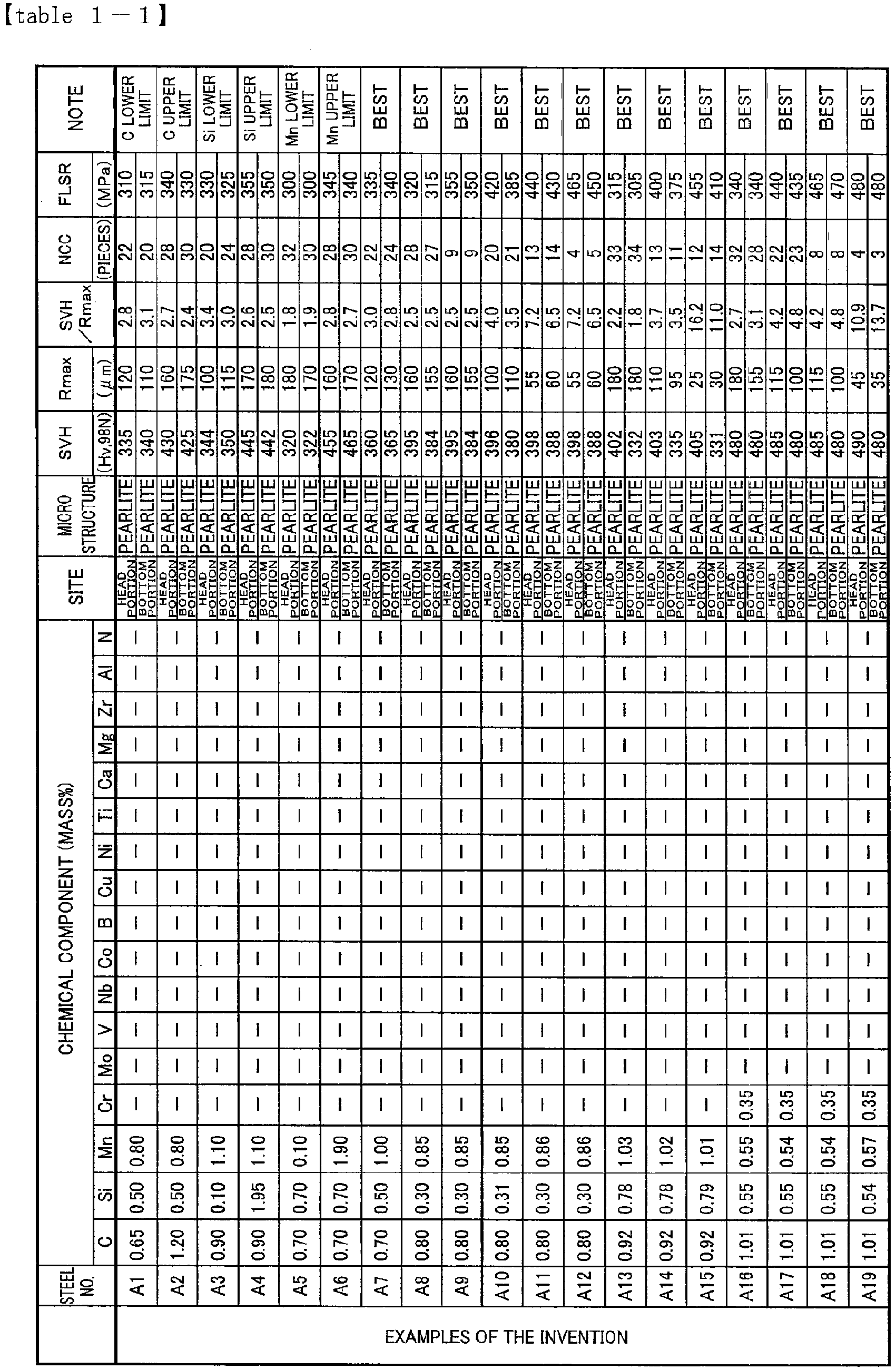

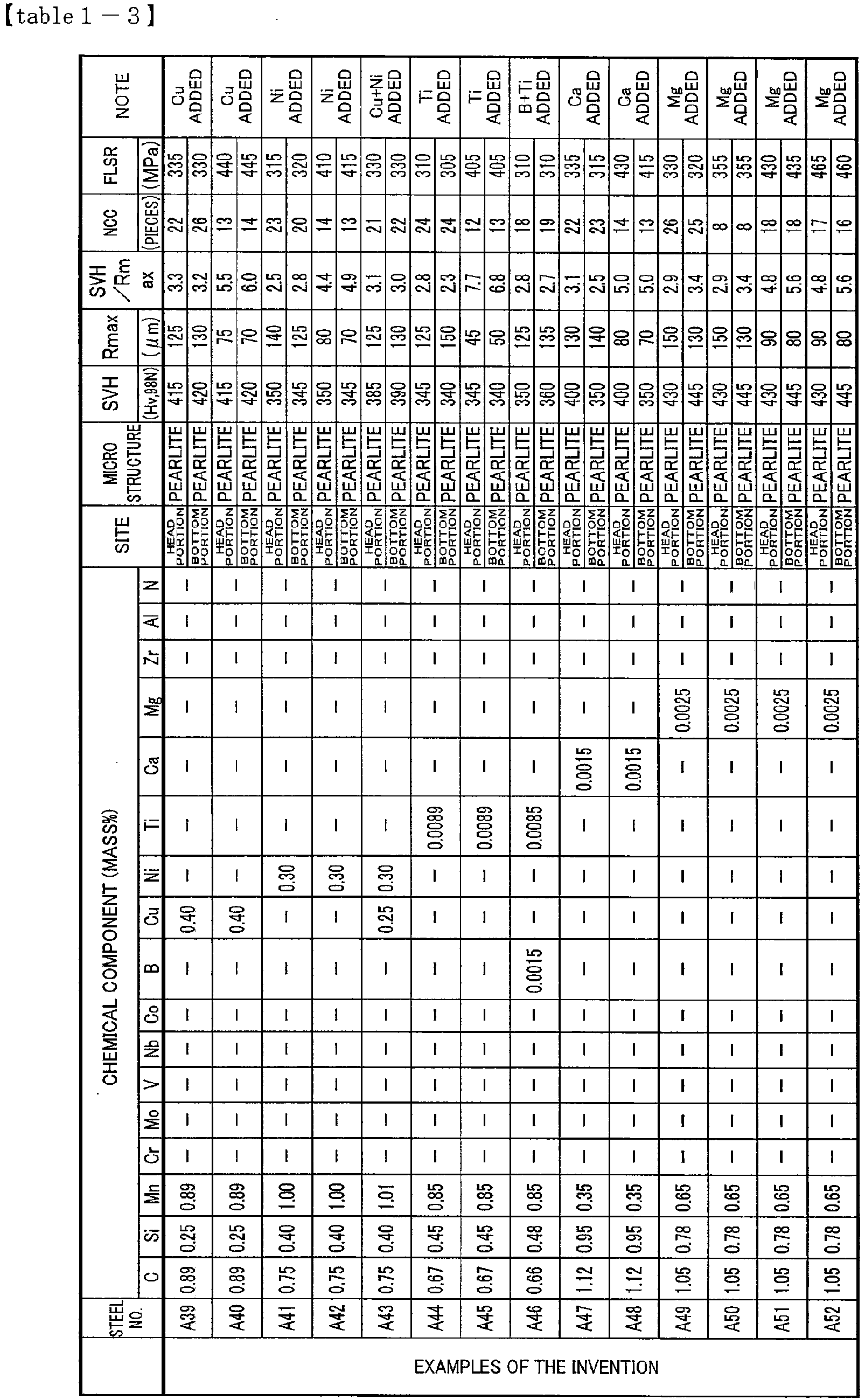


Claims (14)
- A pearlite rail (10) comprising:by mass%,0.65 to 1.20% of C;0.05 to 2.00% of Si;0.05 to 2.00% of Mn; andoptionally, one or more ofone or two kinds of 0.01 to 2.00% of Cr and 0.01 to 0.50% of Mo;one or two kinds of 0.005 to 0.50% of V and 0.002 to 0.050% of Nb;0.01 to 1.00% of Co;0.0001 to 0.0050% of B;0.01 to 1.00% of Cu;0.01 to 1.00% of Ni;0.0050 to 0.0500% of Ti;one or two kinds of 0.0005 to 0.0200% of Mg and 0.0005 to 0.0200% of Ca;0.0001 to 0.2000% of Zr;0.0040 to 1.00% of Al;0.0060 to 0.0200% of N; andthe balance composed of Fe and inevitable impurities,wherein a region at a depth of 5mm from the surface of the head top portion in the head portion (11) and a region at a depth of 5mm from the surface of the sole portion in the bottom portion (12) have a pearlite structure, andthe surface hardness of the pearlite structure measured by a Vickers hardness tester at a load of 98N is in a range of Hv320 to Hv500 and the maximum surface roughness of the pearlite structure is less than or equal to 180 µm, andwherein the maximum surface roughness is defined as a maximum height Rz of a roughness curve described in JIS B 0601, andwherein, in the portion of which the maximum surface roughness is measured,the number of concavities and convexities that exceed 0.30 times the maximum surface roughness with respect to an average value of roughnesses in a rail vertical direction from the bottom portion (12) to the head portion (11) is less than or equal to 40 per length of 5 mm in a rail longitudinal direction of surfaces of the head portion (11) and the bottom portion (12); wherein the number of concavities and convexities is the number of mountains and valleys that exceed a range from the average value of roughness in the rail vertical direction from the head portion (11) to the bottom portion (12).
- The pearlite rail (10) according to claim 1, wherein a ratio of the surface hardness to the maximum surface roughness is greater than or equal to 3.5.
- The pearlite rail (10) according to claim 1 or 2, wherein the pearlite rail contains, by mass%, one or two kinds of 0.01 to 2.00% of Cr and 0.01 to 0.50% of Mo.
- The pearlite rail (10) according to claim 1 or 2, wherein the pearlite rail contains, by mass%, one or two kinds of 0.005 to 0.50% of V and 0.002 to 0.050% of Nb.
- The pearlite rail (10) according to claim 1 or 2, wherein the pearlite rail contains, by mass%, 0.01 to 1.00% of Co.
- The pearlite rail (10) according to claim 1 or 2, wherein the pearlite rail contains, by mass%, 0.0001 to 0.0050% of B.
- The pearlite rail (10) according to claim 1 or 2, wherein the pearlite rail contains, by mass%, 0.01 to 1.00% of Cu.
- The pearlite rail (10) according to claim 1 or 2, wherein the pearlite rail contains, by mass%, 0.01 to 1.00% of Ni.
- The pearlite rail (10) according to claim 1 or 2, wherein the pearlite rail contains, by mass%, 0.0050 to 0.0500% of Ti.
- The pearlite rail (10) according to claim 1 or 2, wherein the pearlite rail contains, by mass%, one or two kinds of 0.0005 to 0.0200% of Mg and 0.0005 to 0.0200% of Ca.
- The pearlite rail (10) according to claim 1 or 2, wherein the pearlite rail contains, by mass%, 0.0001 to 0.2000% of Zr.
- The pearlite rail (10) according to claim 1 or 2, wherein the pearlite rail contains, by mass%, 0.0040 to 1.00% of Al.
- The pearlite rail (10) according to claim 1 or 2, wherein the pearlite rail contains, by mass%, 0.0060 to 0.0200% of N.
- The pearlite rail (10) according to claim 1 or 2, wherein the pearlite rail contains, by mass%:one or two kinds of 0.01 to 2.00% of Cr and 0.01 to 0.50% of Mo;one or two kinds of 0.005 to 0.50% of V and 0.002 to 0.050% of Nb;0.01 to 1.00% of Co;0.0001 to 0.0050% of B;0.01 to 1.00% of Cu;0.01 to 1.00% of Ni;0.0050 to 0.0500% of Ti;0.0005 to 0.0200% of Mg and 0.0005 to 0.0200% of Ca;0.0001 to 0.2000% of Zr;0.0040 to 1.00% of Al; and0.0060 to 0.0200% of N.
Priority Applications (1)
| Application Number | Priority Date | Filing Date | Title |
|---|---|---|---|
| PL10809927T PL2361995T3 (en) | 2009-08-18 | 2010-08-13 | Pearlite rail |
Applications Claiming Priority (2)
| Application Number | Priority Date | Filing Date | Title |
|---|---|---|---|
| JP2009189508 | 2009-08-18 | ||
| PCT/JP2010/063760 WO2011021582A1 (en) | 2009-08-18 | 2010-08-13 | Pearlite rail |
Publications (4)
| Publication Number | Publication Date |
|---|---|
| EP2361995A1 EP2361995A1 (en) | 2011-08-31 |
| EP2361995A4 EP2361995A4 (en) | 2017-07-19 |
| EP2361995B1 EP2361995B1 (en) | 2019-05-15 |
| EP2361995B2 true EP2361995B2 (en) | 2022-12-14 |
Family
ID=43607037
Family Applications (1)
| Application Number | Title | Priority Date | Filing Date |
|---|---|---|---|
| EP10809927.6A Active EP2361995B2 (en) | 2009-08-18 | 2010-08-13 | Pearlite rail |
Country Status (12)
| Country | Link |
|---|---|
| US (1) | US8361246B2 (en) |
| EP (1) | EP2361995B2 (en) |
| JP (1) | JP4805414B2 (en) |
| KR (1) | KR101314338B1 (en) |
| CN (1) | CN102203311B (en) |
| AU (1) | AU2010285725B2 (en) |
| BR (1) | BRPI1006017B1 (en) |
| CA (1) | CA2744992C (en) |
| ES (1) | ES2731660T3 (en) |
| PL (1) | PL2361995T3 (en) |
| RU (1) | RU2476617C1 (en) |
| WO (1) | WO2011021582A1 (en) |
Families Citing this family (25)
| Publication number | Priority date | Publication date | Assignee | Title |
|---|---|---|---|---|
| KR101263102B1 (en) * | 2008-10-31 | 2013-05-09 | 신닛테츠스미킨 카부시키카이샤 | Pearlite rail having superior abrasion resistance and excellent toughness |
| BRPI1007283B1 (en) * | 2009-02-18 | 2017-12-19 | Nippon Steel & Sumitomo Metal Corporation | PERLITICAL RAIL |
| EP2447383B1 (en) | 2009-06-26 | 2018-12-19 | Nippon Steel & Sumitomo Metal Corporation | Pearlite based high-carbon steel rail having excellent ductility and process for production thereof |
| JP5482559B2 (en) * | 2009-08-18 | 2014-05-07 | 新日鐵住金株式会社 | Bainite rail |
| US9127409B2 (en) * | 2012-04-23 | 2015-09-08 | Nippon Steel & Sumitomo Metal Corporation | Rail |
| CN102899586A (en) * | 2012-11-09 | 2013-01-30 | 宁波市鄞州商业精密铸造有限公司 | Iron alloy material and preparation method |
| CN103898303B (en) * | 2012-12-31 | 2016-06-08 | 攀钢集团攀枝花钢铁研究院有限公司 | The heat treatment method of a kind of turnout rail and turnout rail |
| US9670570B2 (en) | 2014-04-17 | 2017-06-06 | Evraz Inc. Na Canada | High carbon steel rail with enhanced ductility |
| AU2015268447B2 (en) * | 2014-05-29 | 2017-09-07 | Nippon Steel Corporation | Rail and production method therefor |
| US10233512B2 (en) * | 2014-05-29 | 2019-03-19 | Nippon Steel & Sumitomo Metal Corporation | Rail and production method therefor |
| CN104032222B (en) | 2014-06-24 | 2016-04-06 | 燕山大学 | The preparation method of nano-beads body of light rail |
| JP6233525B2 (en) * | 2014-09-22 | 2017-11-22 | Jfeスチール株式会社 | Rail manufacturing method and manufacturing apparatus |
| WO2016117692A1 (en) * | 2015-01-23 | 2016-07-28 | 新日鐵住金株式会社 | Rail |
| ES2796328T3 (en) | 2015-01-23 | 2020-11-26 | Nippon Steel Corp | Rail |
| CN105063490B (en) * | 2015-07-23 | 2017-03-22 | 攀钢集团攀枝花钢铁研究院有限公司 | Steel rail for high-speed railway and production method and application of steel rail |
| CN105220066B (en) * | 2015-10-29 | 2017-05-10 | 中北大学 | Nanometer pearlite steel and preparation method thereof |
| JP6658772B2 (en) * | 2016-01-26 | 2020-03-04 | 新東工業株式会社 | Cast steel projectile |
| BR112018073094A2 (en) * | 2016-05-19 | 2019-03-06 | Nippon Steel & Sumitomo Metal Corp | rail |
| CN106521343B (en) * | 2016-11-10 | 2018-03-27 | 钢铁研究总院 | A kind of ultrahigh-strength aluminum alloy Super High Carbon wheel-use steel material and its heat treatment method |
| CN107034413B (en) * | 2016-12-12 | 2018-10-16 | 武汉钢铁有限公司 | The wear-resisting strip of low quenching degree and its manufacturing method |
| WO2019122958A1 (en) * | 2017-12-19 | 2019-06-27 | Arcelormittal | A coated steel substrate |
| WO2019122957A1 (en) * | 2017-12-19 | 2019-06-27 | Arcelormittal | A coated steel substrate |
| CN111989416A (en) * | 2018-03-30 | 2020-11-24 | 杰富意钢铁株式会社 | Guide rail |
| EP3851549A4 (en) * | 2018-09-10 | 2022-07-13 | Nippon Steel Corporation | Rail, and method for manufacturing rail |
| CN112226697B (en) * | 2020-10-19 | 2022-03-22 | 攀钢集团攀枝花钢铁研究院有限公司 | Scratch-resistant rail and production method thereof |
Citations (2)
| Publication number | Priority date | Publication date | Assignee | Title |
|---|---|---|---|---|
| DE2148722A1 (en) † | 1970-10-02 | 1972-05-10 | Wendel Sidelor | Process for the heat treatment of rails with a high resistance to wear and the rails produced thereby |
| US5658400A (en) † | 1993-12-20 | 1997-08-19 | Nippon Steel Corporation | Rails of pearlitic steel with high wear resistance and toughness and their manufacturing methods |
Family Cites Families (19)
| Publication number | Priority date | Publication date | Assignee | Title |
|---|---|---|---|---|
| JPS512616A (en) | 1974-06-25 | 1976-01-10 | Nippon Steel Corp | CHODAIKAJUYONET SUSHORIREERU |
| US5209792A (en) | 1990-07-30 | 1993-05-11 | Nkk Corporation | High-strength, damage-resistant rail |
| SU1839687A3 (en) | 1990-07-30 | 1993-12-30 | Berlington Nortern Rejlroad Ko | Rail, method for its manufacturing and method of its cooling inspection |
| JP3113184B2 (en) | 1995-10-18 | 2000-11-27 | 新日本製鐵株式会社 | Manufacturing method of pearlite rail with excellent wear resistance |
| USRE42668E1 (en) | 1994-11-15 | 2011-09-06 | Nippon Steel Corporation | Pearlitic steel rail having excellent wear resistance and method of producing the same |
| JPH08246100A (en) | 1995-03-07 | 1996-09-24 | Nippon Steel Corp | Pearlitic rail excellent in wear resistance and its production |
| JPH08246101A (en) * | 1995-03-07 | 1996-09-24 | Nippon Steel Corp | Pearlitic rail excellent in wear resistance and damage resistance and its production |
| JP3078461B2 (en) | 1994-11-15 | 2000-08-21 | 新日本製鐵株式会社 | High wear-resistant perlite rail |
| JPH08323626A (en) * | 1995-06-06 | 1996-12-10 | Toshiba Tungaloy Co Ltd | Shot peening method and treated product |
| AT407057B (en) * | 1996-12-19 | 2000-12-27 | Voest Alpine Schienen Gmbh | PROFILED ROLLING MATERIAL AND METHOD FOR THE PRODUCTION THEREOF |
| DE19721915C1 (en) * | 1997-05-26 | 1998-12-10 | Stn Atlas Elektronik Gmbh | Method and device for measuring unevenness in an object surface |
| JP4272385B2 (en) * | 2002-04-05 | 2009-06-03 | 新日本製鐵株式会社 | Perlite rail with excellent wear resistance and ductility |
| EP2388352A1 (en) * | 2002-04-05 | 2011-11-23 | Nippon Steel Corporation | Pearlitic steel rail excellent in wear resistance and ductility and method for producing the same |
| JP4674843B2 (en) * | 2003-04-28 | 2011-04-20 | 新東工業株式会社 | Coil spring manufacturing method |
| JP2005171327A (en) | 2003-12-11 | 2005-06-30 | Nippon Steel Corp | Method for manufacturing pearlite-based rail having excellent surface damage-resistance and internal fatigue damage-resistance, and rail |
| JP4469248B2 (en) * | 2004-03-09 | 2010-05-26 | 新日本製鐵株式会社 | Method for producing high carbon steel rails with excellent wear resistance and ductility |
| JP2006057127A (en) * | 2004-08-18 | 2006-03-02 | Nippon Steel Corp | Pearlitic rail having excellent drop fracture resistance |
| JP2006057128A (en) | 2004-08-18 | 2006-03-02 | Nippon Steel Corp | Method for producing pearlite-series rail excellent in breakage resistance against drop-weight |
| JP4994928B2 (en) | 2007-04-17 | 2012-08-08 | 新日本製鐵株式会社 | Rail manufacturing method with excellent breakage resistance |
-
2010
- 2010-08-13 KR KR1020117009670A patent/KR101314338B1/en active IP Right Grant
- 2010-08-13 AU AU2010285725A patent/AU2010285725B2/en active Active
- 2010-08-13 CA CA2744992A patent/CA2744992C/en active Active
- 2010-08-13 RU RU2011124530/02A patent/RU2476617C1/en active
- 2010-08-13 WO PCT/JP2010/063760 patent/WO2011021582A1/en active Application Filing
- 2010-08-13 EP EP10809927.6A patent/EP2361995B2/en active Active
- 2010-08-13 CN CN2010800030933A patent/CN102203311B/en active Active
- 2010-08-13 PL PL10809927T patent/PL2361995T3/en unknown
- 2010-08-13 ES ES10809927T patent/ES2731660T3/en active Active
- 2010-08-13 US US13/131,804 patent/US8361246B2/en active Active
- 2010-08-13 JP JP2010549757A patent/JP4805414B2/en active Active
- 2010-08-13 BR BRPI1006017-0A patent/BRPI1006017B1/en active IP Right Grant
Patent Citations (2)
| Publication number | Priority date | Publication date | Assignee | Title |
|---|---|---|---|---|
| DE2148722A1 (en) † | 1970-10-02 | 1972-05-10 | Wendel Sidelor | Process for the heat treatment of rails with a high resistance to wear and the rails produced thereby |
| US5658400A (en) † | 1993-12-20 | 1997-08-19 | Nippon Steel Corporation | Rails of pearlitic steel with high wear resistance and toughness and their manufacturing methods |
Non-Patent Citations (2)
| Title |
|---|
| B N PERSSON: "Sliding Friction. Physical Principles and Applications", NANOSCIENCE AND TECHNOLOGY, 1 January 1998 (1998-01-01) † |
| P. WEIDINGER: "Rauhigkeit im Rad-Schiene System", DIPLOMARBEIT INSTITUT FÜR VERFAHRENSTECHNIK DES INDUSTRIELLEN UMWELTSCHUTZES, 23 October 2008 (2008-10-23) † |
Also Published As
| Publication number | Publication date |
|---|---|
| EP2361995A1 (en) | 2011-08-31 |
| US8361246B2 (en) | 2013-01-29 |
| RU2476617C1 (en) | 2013-02-27 |
| WO2011021582A1 (en) | 2011-02-24 |
| CN102203311A (en) | 2011-09-28 |
| BRPI1006017A2 (en) | 2016-05-10 |
| BRPI1006017B1 (en) | 2018-06-19 |
| US20110226389A1 (en) | 2011-09-22 |
| AU2010285725A1 (en) | 2011-02-24 |
| CA2744992A1 (en) | 2011-02-24 |
| ES2731660T3 (en) | 2019-11-18 |
| KR20110060962A (en) | 2011-06-08 |
| EP2361995B1 (en) | 2019-05-15 |
| CN102203311B (en) | 2013-07-24 |
| AU2010285725B2 (en) | 2015-07-23 |
| JPWO2011021582A1 (en) | 2013-01-24 |
| KR101314338B1 (en) | 2013-10-04 |
| JP4805414B2 (en) | 2011-11-02 |
| PL2361995T3 (en) | 2019-09-30 |
| CA2744992C (en) | 2014-02-11 |
| EP2361995A4 (en) | 2017-07-19 |
| RU2011124530A (en) | 2012-12-27 |
Similar Documents
| Publication | Publication Date | Title |
|---|---|---|
| EP2361995B1 (en) | Pearlite rail | |
| JP4824141B2 (en) | Perlite rail with excellent wear resistance and toughness | |
| US9534278B2 (en) | Rail | |
| EP3604600A1 (en) | Method of manufacturing a steel rail | |
| US9127409B2 (en) | Rail | |
| US10563357B2 (en) | Rail and production method therefor | |
| JP5867262B2 (en) | Rail with excellent delayed fracture resistance | |
| JP2011162822A (en) | Pearlite rail having superior wear resistance and method for manufacturing the same | |
| CA2946541C (en) | Rail and production method therefor | |
| EP3988677A1 (en) | Rail and manufacturing method therefor | |
| JP5482559B2 (en) | Bainite rail | |
| WO2017200096A1 (en) | Rail | |
| EP3940090A1 (en) | Rail | |
| JP6631403B2 (en) | Rails with excellent wear resistance and toughness |
Legal Events
| Date | Code | Title | Description |
|---|---|---|---|
| PUAI | Public reference made under article 153(3) epc to a published international application that has entered the european phase |
Free format text: ORIGINAL CODE: 0009012 |
|
| 17P | Request for examination filed |
Effective date: 20110622 |
|
| AK | Designated contracting states |
Kind code of ref document: A1 Designated state(s): AL AT BE BG CH CY CZ DE DK EE ES FI FR GB GR HR HU IE IS IT LI LT LU LV MC MK MT NL NO PL PT RO SE SI SK SM TR |
|
| DAX | Request for extension of the european patent (deleted) | ||
| RAP1 | Party data changed (applicant data changed or rights of an application transferred) |
Owner name: NIPPON STEEL & SUMITOMO METAL CORPORATION |
|
| RIC1 | Information provided on ipc code assigned before grant |
Ipc: C22C 38/58 20060101ALI20170607BHEP Ipc: C21D 9/04 20060101ALI20170607BHEP Ipc: C22C 38/04 20060101ALI20170607BHEP Ipc: C22C 38/00 20060101AFI20170607BHEP Ipc: C22C 38/02 20060101ALI20170607BHEP |
|
| RA4 | Supplementary search report drawn up and despatched (corrected) |
Effective date: 20170619 |
|
| STAA | Information on the status of an ep patent application or granted ep patent |
Free format text: STATUS: EXAMINATION IS IN PROGRESS |
|
| 17Q | First examination report despatched |
Effective date: 20180115 |
|
| GRAP | Despatch of communication of intention to grant a patent |
Free format text: ORIGINAL CODE: EPIDOSNIGR1 |
|
| STAA | Information on the status of an ep patent application or granted ep patent |
Free format text: STATUS: GRANT OF PATENT IS INTENDED |
|
| INTG | Intention to grant announced |
Effective date: 20180803 |
|
| GRAJ | Information related to disapproval of communication of intention to grant by the applicant or resumption of examination proceedings by the epo deleted |
Free format text: ORIGINAL CODE: EPIDOSDIGR1 |
|
| STAA | Information on the status of an ep patent application or granted ep patent |
Free format text: STATUS: EXAMINATION IS IN PROGRESS |
|
| INTC | Intention to grant announced (deleted) | ||
| GRAP | Despatch of communication of intention to grant a patent |
Free format text: ORIGINAL CODE: EPIDOSNIGR1 |
|
| STAA | Information on the status of an ep patent application or granted ep patent |
Free format text: STATUS: GRANT OF PATENT IS INTENDED |
|
| INTG | Intention to grant announced |
Effective date: 20190123 |
|
| GRAS | Grant fee paid |
Free format text: ORIGINAL CODE: EPIDOSNIGR3 |
|
| GRAA | (expected) grant |
Free format text: ORIGINAL CODE: 0009210 |
|
| STAA | Information on the status of an ep patent application or granted ep patent |
Free format text: STATUS: THE PATENT HAS BEEN GRANTED |
|
| AK | Designated contracting states |
Kind code of ref document: B1 Designated state(s): AL AT BE BG CH CY CZ DE DK EE ES FI FR GB GR HR HU IE IS IT LI LT LU LV MC MK MT NL NO PL PT RO SE SI SK SM TR |
|
| REG | Reference to a national code |
Ref country code: CH Ref legal event code: EP Ref country code: GB Ref legal event code: FG4D |
|
| REG | Reference to a national code |
Ref country code: DE Ref legal event code: R096 Ref document number: 602010058941 Country of ref document: DE |
|
| REG | Reference to a national code |
Ref country code: IE Ref legal event code: FG4D |
|
| REG | Reference to a national code |
Ref country code: NL Ref legal event code: MP Effective date: 20190515 |
|
| REG | Reference to a national code |
Ref country code: LT Ref legal event code: MG4D |
|
| PG25 | Lapsed in a contracting state [announced via postgrant information from national office to epo] |
Ref country code: LT Free format text: LAPSE BECAUSE OF FAILURE TO SUBMIT A TRANSLATION OF THE DESCRIPTION OR TO PAY THE FEE WITHIN THE PRESCRIBED TIME-LIMIT Effective date: 20190515 Ref country code: HR Free format text: LAPSE BECAUSE OF FAILURE TO SUBMIT A TRANSLATION OF THE DESCRIPTION OR TO PAY THE FEE WITHIN THE PRESCRIBED TIME-LIMIT Effective date: 20190515 Ref country code: NL Free format text: LAPSE BECAUSE OF FAILURE TO SUBMIT A TRANSLATION OF THE DESCRIPTION OR TO PAY THE FEE WITHIN THE PRESCRIBED TIME-LIMIT Effective date: 20190515 Ref country code: FI Free format text: LAPSE BECAUSE OF FAILURE TO SUBMIT A TRANSLATION OF THE DESCRIPTION OR TO PAY THE FEE WITHIN THE PRESCRIBED TIME-LIMIT Effective date: 20190515 Ref country code: PT Free format text: LAPSE BECAUSE OF FAILURE TO SUBMIT A TRANSLATION OF THE DESCRIPTION OR TO PAY THE FEE WITHIN THE PRESCRIBED TIME-LIMIT Effective date: 20190915 Ref country code: NO Free format text: LAPSE BECAUSE OF FAILURE TO SUBMIT A TRANSLATION OF THE DESCRIPTION OR TO PAY THE FEE WITHIN THE PRESCRIBED TIME-LIMIT Effective date: 20190815 Ref country code: SE Free format text: LAPSE BECAUSE OF FAILURE TO SUBMIT A TRANSLATION OF THE DESCRIPTION OR TO PAY THE FEE WITHIN THE PRESCRIBED TIME-LIMIT Effective date: 20190515 Ref country code: AL Free format text: LAPSE BECAUSE OF FAILURE TO SUBMIT A TRANSLATION OF THE DESCRIPTION OR TO PAY THE FEE WITHIN THE PRESCRIBED TIME-LIMIT Effective date: 20190515 |
|
| REG | Reference to a national code |
Ref country code: ES Ref legal event code: FG2A Ref document number: 2731660 Country of ref document: ES Kind code of ref document: T3 Effective date: 20191118 |
|
| PG25 | Lapsed in a contracting state [announced via postgrant information from national office to epo] |
Ref country code: BG Free format text: LAPSE BECAUSE OF FAILURE TO SUBMIT A TRANSLATION OF THE DESCRIPTION OR TO PAY THE FEE WITHIN THE PRESCRIBED TIME-LIMIT Effective date: 20190815 Ref country code: GR Free format text: LAPSE BECAUSE OF FAILURE TO SUBMIT A TRANSLATION OF THE DESCRIPTION OR TO PAY THE FEE WITHIN THE PRESCRIBED TIME-LIMIT Effective date: 20190816 Ref country code: LV Free format text: LAPSE BECAUSE OF FAILURE TO SUBMIT A TRANSLATION OF THE DESCRIPTION OR TO PAY THE FEE WITHIN THE PRESCRIBED TIME-LIMIT Effective date: 20190515 |
|
| PG25 | Lapsed in a contracting state [announced via postgrant information from national office to epo] |
Ref country code: EE Free format text: LAPSE BECAUSE OF FAILURE TO SUBMIT A TRANSLATION OF THE DESCRIPTION OR TO PAY THE FEE WITHIN THE PRESCRIBED TIME-LIMIT Effective date: 20190515 Ref country code: SK Free format text: LAPSE BECAUSE OF FAILURE TO SUBMIT A TRANSLATION OF THE DESCRIPTION OR TO PAY THE FEE WITHIN THE PRESCRIBED TIME-LIMIT Effective date: 20190515 Ref country code: RO Free format text: LAPSE BECAUSE OF FAILURE TO SUBMIT A TRANSLATION OF THE DESCRIPTION OR TO PAY THE FEE WITHIN THE PRESCRIBED TIME-LIMIT Effective date: 20190515 Ref country code: DK Free format text: LAPSE BECAUSE OF FAILURE TO SUBMIT A TRANSLATION OF THE DESCRIPTION OR TO PAY THE FEE WITHIN THE PRESCRIBED TIME-LIMIT Effective date: 20190515 |
|
| REG | Reference to a national code |
Ref country code: DE Ref legal event code: R026 Ref document number: 602010058941 Country of ref document: DE |
|
| PLBI | Opposition filed |
Free format text: ORIGINAL CODE: 0009260 |
|
| PG25 | Lapsed in a contracting state [announced via postgrant information from national office to epo] |
Ref country code: SM Free format text: LAPSE BECAUSE OF FAILURE TO SUBMIT A TRANSLATION OF THE DESCRIPTION OR TO PAY THE FEE WITHIN THE PRESCRIBED TIME-LIMIT Effective date: 20190515 |
|
| PLAX | Notice of opposition and request to file observation + time limit sent |
Free format text: ORIGINAL CODE: EPIDOSNOBS2 |
|
| REG | Reference to a national code |
Ref country code: DE Ref legal event code: R119 Ref document number: 602010058941 Country of ref document: DE |
|
| 26 | Opposition filed |
Opponent name: VOESTALPINE SCHIENEN GMBH Effective date: 20200217 |
|
| PG25 | Lapsed in a contracting state [announced via postgrant information from national office to epo] |
Ref country code: TR Free format text: LAPSE BECAUSE OF FAILURE TO SUBMIT A TRANSLATION OF THE DESCRIPTION OR TO PAY THE FEE WITHIN THE PRESCRIBED TIME-LIMIT Effective date: 20190515 |
|
| REG | Reference to a national code |
Ref country code: AT Ref legal event code: UEP Ref document number: 1133509 Country of ref document: AT Kind code of ref document: T Effective date: 20190515 |
|
| PG25 | Lapsed in a contracting state [announced via postgrant information from national office to epo] |
Ref country code: CH Free format text: LAPSE BECAUSE OF NON-PAYMENT OF DUE FEES Effective date: 20190831 Ref country code: LI Free format text: LAPSE BECAUSE OF NON-PAYMENT OF DUE FEES Effective date: 20190831 Ref country code: MC Free format text: LAPSE BECAUSE OF FAILURE TO SUBMIT A TRANSLATION OF THE DESCRIPTION OR TO PAY THE FEE WITHIN THE PRESCRIBED TIME-LIMIT Effective date: 20190515 Ref country code: SI Free format text: LAPSE BECAUSE OF FAILURE TO SUBMIT A TRANSLATION OF THE DESCRIPTION OR TO PAY THE FEE WITHIN THE PRESCRIBED TIME-LIMIT Effective date: 20190515 |
|
| REG | Reference to a national code |
Ref country code: BE Ref legal event code: MM Effective date: 20190831 |
|
| PLBB | Reply of patent proprietor to notice(s) of opposition received |
Free format text: ORIGINAL CODE: EPIDOSNOBS3 |
|
| PG25 | Lapsed in a contracting state [announced via postgrant information from national office to epo] |
Ref country code: IE Free format text: LAPSE BECAUSE OF NON-PAYMENT OF DUE FEES Effective date: 20190813 Ref country code: DE Free format text: LAPSE BECAUSE OF NON-PAYMENT OF DUE FEES Effective date: 20200303 |
|
| PG25 | Lapsed in a contracting state [announced via postgrant information from national office to epo] |
Ref country code: BE Free format text: LAPSE BECAUSE OF NON-PAYMENT OF DUE FEES Effective date: 20190831 |
|
| PGFP | Annual fee paid to national office [announced via postgrant information from national office to epo] |
Ref country code: CZ Payment date: 20200804 Year of fee payment: 11 Ref country code: FR Payment date: 20200715 Year of fee payment: 11 Ref country code: LU Payment date: 20200724 Year of fee payment: 11 Ref country code: GB Payment date: 20200818 Year of fee payment: 11 |
|
| PGFP | Annual fee paid to national office [announced via postgrant information from national office to epo] |
Ref country code: PL Payment date: 20200715 Year of fee payment: 11 Ref country code: IT Payment date: 20200713 Year of fee payment: 11 |
|
| PG25 | Lapsed in a contracting state [announced via postgrant information from national office to epo] |
Ref country code: CY Free format text: LAPSE BECAUSE OF FAILURE TO SUBMIT A TRANSLATION OF THE DESCRIPTION OR TO PAY THE FEE WITHIN THE PRESCRIBED TIME-LIMIT Effective date: 20190515 |
|
| PG25 | Lapsed in a contracting state [announced via postgrant information from national office to epo] |
Ref country code: IS Free format text: LAPSE BECAUSE OF FAILURE TO SUBMIT A TRANSLATION OF THE DESCRIPTION OR TO PAY THE FEE WITHIN THE PRESCRIBED TIME-LIMIT Effective date: 20190915 |
|
| PG25 | Lapsed in a contracting state [announced via postgrant information from national office to epo] |
Ref country code: HU Free format text: LAPSE BECAUSE OF FAILURE TO SUBMIT A TRANSLATION OF THE DESCRIPTION OR TO PAY THE FEE WITHIN THE PRESCRIBED TIME-LIMIT; INVALID AB INITIO Effective date: 20100813 Ref country code: MT Free format text: LAPSE BECAUSE OF FAILURE TO SUBMIT A TRANSLATION OF THE DESCRIPTION OR TO PAY THE FEE WITHIN THE PRESCRIBED TIME-LIMIT Effective date: 20190515 |
|
| APAH | Appeal reference modified |
Free format text: ORIGINAL CODE: EPIDOSCREFNO |
|
| APBM | Appeal reference recorded |
Free format text: ORIGINAL CODE: EPIDOSNREFNO |
|
| APBP | Date of receipt of notice of appeal recorded |
Free format text: ORIGINAL CODE: EPIDOSNNOA2O |
|
| APBU | Appeal procedure closed |
Free format text: ORIGINAL CODE: EPIDOSNNOA9O |
|
| GBPC | Gb: european patent ceased through non-payment of renewal fee |
Effective date: 20210813 |
|
| PG25 | Lapsed in a contracting state [announced via postgrant information from national office to epo] |
Ref country code: LU Free format text: LAPSE BECAUSE OF NON-PAYMENT OF DUE FEES Effective date: 20210813 Ref country code: CZ Free format text: LAPSE BECAUSE OF NON-PAYMENT OF DUE FEES Effective date: 20210813 |
|
| PG25 | Lapsed in a contracting state [announced via postgrant information from national office to epo] |
Ref country code: MK Free format text: LAPSE BECAUSE OF FAILURE TO SUBMIT A TRANSLATION OF THE DESCRIPTION OR TO PAY THE FEE WITHIN THE PRESCRIBED TIME-LIMIT Effective date: 20190515 |
|
| PG25 | Lapsed in a contracting state [announced via postgrant information from national office to epo] |
Ref country code: IT Free format text: LAPSE BECAUSE OF NON-PAYMENT OF DUE FEES Effective date: 20210813 Ref country code: GB Free format text: LAPSE BECAUSE OF NON-PAYMENT OF DUE FEES Effective date: 20210813 Ref country code: FR Free format text: LAPSE BECAUSE OF NON-PAYMENT OF DUE FEES Effective date: 20210831 |
|
| PGFP | Annual fee paid to national office [announced via postgrant information from national office to epo] |
Ref country code: ES Payment date: 20220901 Year of fee payment: 13 |
|
| PUAH | Patent maintained in amended form |
Free format text: ORIGINAL CODE: 0009272 |
|
| STAA | Information on the status of an ep patent application or granted ep patent |
Free format text: STATUS: PATENT MAINTAINED AS AMENDED |
|
| 27A | Patent maintained in amended form |
Effective date: 20221214 |
|
| AK | Designated contracting states |
Kind code of ref document: B2 Designated state(s): AL AT BE BG CH CY CZ DE DK EE ES FI FR GB GR HR HU IE IS IT LI LT LU LV MC MK MT NL NO PL PT RO SE SI SK SM TR |
|
| REG | Reference to a national code |
Ref country code: DE Ref legal event code: R102 Ref document number: 602010058941 Country of ref document: DE |
|
| PG25 | Lapsed in a contracting state [announced via postgrant information from national office to epo] |
Ref country code: ES Free format text: LAPSE BECAUSE OF FAILURE TO SUBMIT A TRANSLATION OF THE DESCRIPTION OR TO PAY THE FEE WITHIN THE PRESCRIBED TIME-LIMIT Effective date: 20221214 |
|
| PGFP | Annual fee paid to national office [announced via postgrant information from national office to epo] |
Ref country code: AT Payment date: 20230725 Year of fee payment: 14 |