EP2361663A1 - Filterpaneel für Sicherheits-Einspritz- und Beregnungskreislauf eines Kernreaktors - Google Patents
Filterpaneel für Sicherheits-Einspritz- und Beregnungskreislauf eines Kernreaktors Download PDFInfo
- Publication number
- EP2361663A1 EP2361663A1 EP10176542A EP10176542A EP2361663A1 EP 2361663 A1 EP2361663 A1 EP 2361663A1 EP 10176542 A EP10176542 A EP 10176542A EP 10176542 A EP10176542 A EP 10176542A EP 2361663 A1 EP2361663 A1 EP 2361663A1
- Authority
- EP
- European Patent Office
- Prior art keywords
- filter
- support plate
- panel
- perforated
- filter element
- Prior art date
- Legal status (The legal status is an assumption and is not a legal conclusion. Google has not performed a legal analysis and makes no representation as to the accuracy of the status listed.)
- Withdrawn
Links
- 239000007924 injection Substances 0.000 title claims abstract description 13
- 238000002347 injection Methods 0.000 title claims abstract description 13
- 238000001914 filtration Methods 0.000 title claims description 14
- XLYOFNOQVPJJNP-UHFFFAOYSA-N water Substances O XLYOFNOQVPJJNP-UHFFFAOYSA-N 0.000 claims abstract description 31
- 239000000498 cooling water Substances 0.000 claims abstract description 7
- 229910052751 metal Inorganic materials 0.000 claims abstract description 5
- 239000002184 metal Substances 0.000 claims abstract description 5
- 238000005507 spraying Methods 0.000 claims description 7
- 230000003014 reinforcing effect Effects 0.000 claims description 3
- 125000006850 spacer group Chemical group 0.000 claims description 3
- 229910001220 stainless steel Inorganic materials 0.000 claims description 3
- 208000018747 cerebellar ataxia with neuropathy and bilateral vestibular areflexia syndrome Diseases 0.000 claims description 2
- 239000004744 fabric Substances 0.000 description 4
- 239000007921 spray Substances 0.000 description 4
- 230000004888 barrier function Effects 0.000 description 2
- 239000012530 fluid Substances 0.000 description 2
- 229910052782 aluminium Inorganic materials 0.000 description 1
- XAGFODPZIPBFFR-UHFFFAOYSA-N aluminium Chemical compound [Al] XAGFODPZIPBFFR-UHFFFAOYSA-N 0.000 description 1
- 239000011248 coating agent Substances 0.000 description 1
- 238000000576 coating method Methods 0.000 description 1
- 230000000295 complement effect Effects 0.000 description 1
- 238000001816 cooling Methods 0.000 description 1
- 230000007797 corrosion Effects 0.000 description 1
- 238000005260 corrosion Methods 0.000 description 1
- 238000006073 displacement reaction Methods 0.000 description 1
- 230000005611 electricity Effects 0.000 description 1
- 238000000605 extraction Methods 0.000 description 1
- 238000011010 flushing procedure Methods 0.000 description 1
- 239000011888 foil Substances 0.000 description 1
- 239000003758 nuclear fuel Substances 0.000 description 1
- 230000005855 radiation Effects 0.000 description 1
- 238000007789 sealing Methods 0.000 description 1
- 239000000243 solution Substances 0.000 description 1
- 239000010935 stainless steel Substances 0.000 description 1
- 238000003466 welding Methods 0.000 description 1
Images


Classifications
-
- B—PERFORMING OPERATIONS; TRANSPORTING
- B01—PHYSICAL OR CHEMICAL PROCESSES OR APPARATUS IN GENERAL
- B01D—SEPARATION
- B01D29/00—Filters with filtering elements stationary during filtration, e.g. pressure or suction filters, not covered by groups B01D24/00 - B01D27/00; Filtering elements therefor
- B01D29/11—Filters with filtering elements stationary during filtration, e.g. pressure or suction filters, not covered by groups B01D24/00 - B01D27/00; Filtering elements therefor with bag, cage, hose, tube, sleeve or like filtering elements
- B01D29/111—Making filtering elements
-
- B—PERFORMING OPERATIONS; TRANSPORTING
- B01—PHYSICAL OR CHEMICAL PROCESSES OR APPARATUS IN GENERAL
- B01D—SEPARATION
- B01D29/00—Filters with filtering elements stationary during filtration, e.g. pressure or suction filters, not covered by groups B01D24/00 - B01D27/00; Filtering elements therefor
- B01D29/39—Filters with filtering elements stationary during filtration, e.g. pressure or suction filters, not covered by groups B01D24/00 - B01D27/00; Filtering elements therefor with hollow discs side by side on, or around, one or more tubes, e.g. of the leaf type
Definitions
- the present invention relates to a filter panel for a safety injection and spraying circuit of a nuclear reactor.
- a primary water circuit comprises a water circulation pump in a closed circuit in the reactor vessel and in a steam generator exchanger.
- the water of the primary circuit is heated in the tank of the generator in contact with the nuclear fuel, this heat then being transferred in the exchanger to a secondary fluid which vaporizes, this vapor being used in turbogenerators generating electricity.
- the building containing the reactor constitutes a sealed concrete containment enclosure which is internally covered with a waterproof skin coating.
- the reactor vessel and the primary circuit are enclosed in another concrete enclosure called "missile barrier", made inside the containment and defining an annular space with the sealing skin of the latter.
- the role of the anti-missile barrier is to protect the devices arranged in the annular space and to seal the containment against possible accidental projections from the reactor core or the primary circuit.
- the upper part of the tank opens at the bottom of a pool filled with water trapping radiation during extraction and refueling operations.
- the pool is emptied and the water is stored in a holding tank.
- a breach in the primary circuit would cause an excessive rise in temperature in the reactor core, causing it to melt.
- the water of the primary circuit would vaporize in the enclosure of containment and pressurize the latter, causing a risk of rupture of the enclosure.
- the reactor core by water injection.
- it is intended to spray water to condense the steam produced by the breach in the containment and to cool the walls of the enclosure.
- the water used is drawn from the holding tank.
- the runoff water which is collected in an annular space located in the lower part of the containment enclosure, feeds the safety injection and spray system of the nuclear reactor.
- This annular space is equipped with filter modules arranged in series and filtering the runoff water before it is taken up in a collection and circulation channel.
- the modules are used to retain debris produced in the event of an accident, in order to avoid damage to pumps and injection and water spray nozzles.
- a filter module comprises a plurality of parallel filter panels each comprising two corrugated sheets corrugated and welded to a support plate, which form between them and the support plate circulation channels each having a water outlet end facing the collection channel.
- the runoff water is then filtered through the fine perforations of the corrugated sheets and then flows into the circulation channels of the filter panels into the collection channel where it is drawn by means of the pumps.
- the invention aims in particular to provide a simple, effective and economical solution to these problems.
- a filter panel for a safety injection and spraying circuit of a nuclear reactor comprising a support plate on which is fixed at least one filtering element such as a perforated plate or a wire mesh , the support plate and the filter element forming between them at least one cooling water circulation channel, said channel comprising an open water outlet end, characterized in that the filtering element is fixed to the support plate by hooking means or by bolting.
- the hooking means or the bolts make it possible to simply, rapidly and accurately fix the perforated plate (s) or the metal sheets on the support plate. This type of fastening also does not generate local deformation, so that the addition of additional seals is unnecessary.
- the attachment means comprise openings in the support plate, cooperating with hooks of the filter element, or vice versa.
- the filter panel comprises a plurality of perforated sheets adjacent to each other.
- the or each perforated sheet has a section W, so as to offer good impact resistance and a large filtration area.
- the filter panel comprises at least two filter elements, hung on either side of the support plate.
- the filtration surface is thus increased.
- the filtering panel comprises two U-shaped upper and lower sections, mounted and fastened by hooking on the lower and upper edges of the support plate, the lower section comprising openings for the passage of cooling, arranged opposite the open ends of the channels cooling water circulation, the other ends of said channels being closed by the upper profile.
- hooks are formed on the vertical and / or horizontal edges of the perforated sheets and / or the support plate.
- the filter element is corrugated and has recessed areas bearing against the support plate and projecting zones, the filter element being fixed to the support plate by means of bolts. mounted in some of the recessed areas and comprising a nut and / or a screw head of triangular or trapezoidal general section, having two oblique bearing faces on inclined flanks of the filter element.
- This variant also makes it possible to simply, rapidly and precisely fix the filter element or elements on the support plate, the bolting not causing local deformation of the sheets.
- the attachment means comprise means for gripping at least one edge of the filter element.
- the clamping means comprise two profiles arranged on either side of the filter element and each comprising teeth inserted in the corresponding recessed areas, so as to pinch the edge of the filter element between the profiles.
- the invention further relates to a filter module for a safety injection and spraying circuit of a nuclear reactor, characterized in that it comprises a plurality of filter panels of the aforementioned type, which are spaced apart from each other. others via spacers, and are mounted on a frame having a lower box forming a channel for collecting and circulating water.
- the filtering module comprises two reinforcing elements each comprising beams arranged in a cross and extending across the ends of the panels on two vertical side faces of the module.
- the frame comprises perforated plates disposed under the filter panels, and the dimensions of the water passage openings are determined for uniform flow rates in several modules arranged in series.
- the channel of a filter module can be connected to the channel of an adjacent module by stainless steel V-joints resiliently mounted between the end flanges of the channels of the two modules.
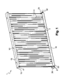
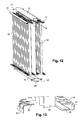
- FIGS. Figures 1 to 7 A filter panel 1 according to the invention for a safety injection and spraying circuit of a nuclear reactor is shown in FIGS. Figures 1 to 7 . It comprises a flat support plate 2 (see figures 5 and 7 ), of rectangular shape, on either side of which are fixed corrugated sheets 3, 4, more particularly sheets of section W. These plates are formed by folding with a good dimensional accuracy, which allows to fix them side by side on the support plate substantially sealingly.
- the support sheet 2 comprises first series of five openings 6 vertically aligned and regularly distributed from an upper edge 7 to a lower edge 8 of the support plate 2.
- the first series of openings 6 are spaced apart horizontally a distance 1, the openings 6 of the same series being spaced vertically by a distance h.
- the support sheet 5 further comprises second sets of five openings 9, similar to those described above.
- the second series of openings 9 are spaced horizontally by a distance 1, the openings 9 of the same series being spaced vertically by a distance h.
- the openings 9 of the second series are arranged a little above the openings 6 of the first series and are slightly displaced horizontally by a distance d, as can be seen more clearly in FIG. figure 7 .
- the filter panel 1 further comprises first sheets 3 of W section, arranged adjacent to each other and hung on one side of the support plate 2.
- Each corrugated sheet 3 thus comprises two vertical lateral edges, formed by the ends of the W, equipped with hooks 10 inserted in the openings 6 of the first corresponding series.
- the hooking is carried out by inserting the hooks 10 into the openings 6 and moving the first sheets downwards so that the hooks are locked on the edges of the openings 6 of the support plate 2.
- the lateral edges of each sheet are straight edges, perpendicular to the support plate and the side edges of two adjacent sheets are applied to one another substantially sealingly.
- the filter panel 1 further comprises second sheets 4 of W section and having hooks 10, arranged on the other side of the support plate 2.
- the hooks 10 of the second sheets 4 are inserted into the openings 9 of the second series corresponding and hooked or locked on the support plate 2 in the same manner as before.
- the slight horizontal displacement of the first and second series of openings 6, 9 allows the hooks 10 to pass freely through the openings, without being blocked by the opposite plates 4, 3.
- Each sheet 3, 4 in W comprises perforations of small diameter (not visible), arranged staggered with respect to each other.
- each perforated plate 3, 4 and the support plate 2 define between them water circulation channels 11. More particularly, each perforated plate 3, 4 defines two vertical parallel channels 11 with the support plate 2.
- the upper and lower horizontal edges 7, 8 of the support plate 2 are equipped with hooks 12, turned in the same direction, as is better visible at Figures 3 and 4 .
- the filter panel is also equipped with an upper U section section 13, covering the upper edge of the perforated sheets 3, 4 and the support plate 2.
- the upper profile 13 has openings 14 ( figure 3 ) for hooking hooks 12 of the support plate 2 and is equipped with two plates 15 closing its ends.
- Each plate 15 has two tapped holes 16 parallel to the axis of the profile and is traversed perpendicularly by a bolt 17 for fixing the plate 15 to the profile 13.
- the panel 1 further comprises a lower profile 18 of U-section, covering the lower edge of the perforated plates 3, 4 and the support plate 2.
- the lower profile 18 has openings 19 in the general shape of rhombus, the hooks 12 coming to lock on the edges of certain openings 19.
- Each opening 19 is arranged facing two opposite channels 11, located on either side of the support plate 2.
- the shape of the openings 19 is complementary to that of the opposite channels 11.
- the lower section 18 is equipped with two plates 20 closing its ends.
- Each plate 20 has two threaded holes 21 parallel to the axis of the profile and is traversed perpendicularly by two bolts 22 for fixing the plate 20 to the profile 18.
- the nuts of the bolts 17, 22 are arranged outside the water circulation channels 11, so that in case of loosening, these nuts can not be sucked by the pump.
- the dimensions of the panels 1 can be adapted as needed.
- each panel has a length of 1300 mm and a height of 1100 mm
- the perforations of the sheets are holes of a diameter of 2 mm, arranged in staggered rows, and the sum of the surfaces of the holes of a sheet represents 35% of the surface of the sheet.
- each panel 1 could comprise perforated sheets on one side of the support plate 2 and the support plate 2 could be curved.
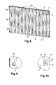
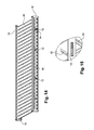
- FIGS. 8 to 10 illustrate an alternative embodiment of the invention in which the perforated sheets 3,4 are of great length and are fixed to the support plate 2 by means of bolts, each sheet 3, 4 making the length of a filter panel.
- the sheets 2 to 4 are fixed together by means of bolts 30 disposed at the hollow areas 31 of the perforated plates 3, 4.
- the support plate 2 has holes for passing a screw.
- the screw head and the nut 32 of the bolts 30 each having a generally triangular or trapezoidal shape, having two oblique faces 33 for bearing on inclined flanks of the perforated plates 3, 4 ( figure 10 ).
- the filter panels comprising the corrugated sheets 3, 4 are equipped with upper and lower profiles mounted by hooking, as already described with reference to the Figures 1 to 6 .
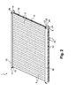
- FIGS 11 to 15 show an alternative embodiment of the invention, wherein the sheets 3, 4 corrugated and perforated are replaced by woven and waved metal webs 30 mounted both sides of the support plate 2 and extending over the entire surface thereof. These fabrics 30 ensure the filtration of water, in the same way as the sheets 3, 4 described above.
- Each fabric 30 is preformed with corrugations as shown and is fixed by means of attachment means each comprising an outer U-shaped profile 31, fixed on the lower or upper profile 18, 13, and an L-shaped section 32, fixed on the support plate 2.
- each profile comprises teeth 33 intended to be inserted into the recessed zones formed by the corresponding corrugated fabric 30.
- the teeth 33 of the external section 31 extend in the direction of the support plate 2 and the teeth 33 of the internal profile 32 s 'extend outward. The lower and upper edges of the cloths 30 are thus held by wedging between the teeth 33 of the opposite sections 31, 32.
- the lower profile 18 comprises, in this variant embodiment, two oblong openings 34 extending over almost the entire length of the profile 18, the openings 3 'being separated by a median strip 35 allowing the attachment of the hooks 12 of the support plate 2 ( Figures 14 and 15 ).
- the external profiles 31 of the attachment means comprise similar oblong openings 36, located opposite the openings 34 of the lower profile 18.
- the teeth 33 of the lower internal profiles 32 are also perforated to allow the flow of water in the flow channels 11 leading to the openings 36 and 34. It is not necessary that the teeth 33 of the outer sections 31 are perforated. because these do not extend across said channels 11.
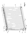
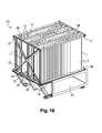
- the figure 16 shows a filter module 23 according to the invention, intended for a safety injection and spray circuit of a nuclear reactor, comprising a plurality of filter panels 1 attached to a frame comprising a lower box 24 forming a collection channel and water circulation.
- the module further comprises two horizontal sections 25, 26, respectively lower and upper, at the lateral ends of the panels 1.
- the panels 1 are fixed to the upper horizontal profiles 26 by means of screws screwed into the holes 16 of the plates 15. and to the lower horizontal sections 25 by means of screws screwed into the holes 21 of the plates 20.
- the module further comprises two reinforcing elements each formed of four beams 27 arranged diagonally and extending across the ends of the panels 1 on two vertical lateral faces of the module 26.
- U-shaped spacers 28 are mounted on the frame between the panels 1, more precisely between the lower sections 18.
- the frame finally comprises perforated plates (not visible), arranged under the filtering panels 1, and whose dimensions of the water passage openings are determined for uniform flow rates in several modules arranged in series.
- the openings of the plates located at a distance from the circulation pump are larger and therefore generate fewer pressure drops than the openings of the plates closest to the pump.
- the upper wall of the channel 24 for collecting and circulating water is thus sealed, only the openings 19 of the filtering panels 1 opening into said channel 24.
- the modules 23 are arranged in series.
- 16 modules are arranged in series, each module comprising 5 filter panels.
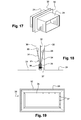
- a filter module 23 is connected to an adjacent module by V-shaped joints for example aluminum resiliently mounted between the flanges of the ends of the channels of the two modules.
- Each module 23 then comprises a fixed point around which the module is subjected to expansions.
- the seals are dimensioned so as to compensate for these expansions.
- each gasket 31 has a generally rectangular shape corresponding to the shape of the flanges 30 between which it is mounted, and comprises a central plate 32 in the form of a rectangular frame on each side of which is fixed a thin sheet or foil 33 forming a spring, covered externally of a canvas 34 of stainless steel wire.
- Fixing is performed on the inner edge of the central plate 32, by means of an L-shaped bracket 35 and a plate 36 which clamp the edges of the thin sheets 33 and webs 34 on the central plate 32 and which are assembled by welded studs 37.
- the central plate 32 is in one piece, as are the canvases 34 to ensure the continuity of the seal in the corners of the joint, while the thin sheets 33 are formed of four straight strips and that, likewise, angles 35 and plates 36 are each formed of four rectilinear elements.
- the thin sheets 33 and the webs 34 deviate V outwards from the inner edge of the central plate 32.
- the seal 31 can be slidably mounted between the flanges 30 of the channels 24 of the installed modules and makes it possible to compensate for the differences in position of these flanges with respect to each other.
- the pressure which is stronger outside the modules acts inside the V formed by the seals 31 and applies the thin sheets 33 and the cloths 34 to the flanges 30 of the channels of the modules.
- the water contained in the annular space in the lower part of the confinement chamber enters the fluid circulation channels 11 through the perforations of the sheets 3, 4 of the filtering panels 1, and then opens into the channel 24 via the openings 19, the water harvested being then sucked by the pump.
Landscapes
- Chemical & Material Sciences (AREA)
- Chemical Kinetics & Catalysis (AREA)
- Structure Of Emergency Protection For Nuclear Reactors (AREA)
- Filtration Of Liquid (AREA)
Applications Claiming Priority (1)
| Application Number | Priority Date | Filing Date | Title |
|---|---|---|---|
| FR1000339A FR2955695B1 (fr) | 2010-01-28 | 2010-01-28 | Panneau filtrant pour circuit d'injection de securite et d'aspersion d'un reacteur nucleaire |
Publications (1)
| Publication Number | Publication Date |
|---|---|
| EP2361663A1 true EP2361663A1 (de) | 2011-08-31 |
Family
ID=42664759
Family Applications (1)
| Application Number | Title | Priority Date | Filing Date |
|---|---|---|---|
| EP10176542A Withdrawn EP2361663A1 (de) | 2010-01-28 | 2010-09-14 | Filterpaneel für Sicherheits-Einspritz- und Beregnungskreislauf eines Kernreaktors |
Country Status (3)
| Country | Link |
|---|---|
| EP (1) | EP2361663A1 (de) |
| CN (1) | CN102142286B (de) |
| FR (1) | FR2955695B1 (de) |
Cited By (1)
| Publication number | Priority date | Publication date | Assignee | Title |
|---|---|---|---|---|
| CN107596819A (zh) * | 2017-11-07 | 2018-01-19 | 无锡风正科技有限公司 | Hepa过滤器用免打折胶线式滤网结构及其制造方法 |
Families Citing this family (1)
| Publication number | Priority date | Publication date | Assignee | Title |
|---|---|---|---|---|
| CN115554749A (zh) * | 2022-09-26 | 2023-01-03 | 中国核电工程有限公司 | 一种过滤结构、过滤组件及过滤器 |
Citations (7)
| Publication number | Priority date | Publication date | Assignee | Title |
|---|---|---|---|---|
| US3441143A (en) * | 1967-02-10 | 1969-04-29 | Marvel Eng Co | Plural element filter assembly |
| FR2588765A1 (fr) * | 1985-10-17 | 1987-04-24 | Gaudfrin Guy | Filtre pour liquides charges de particules solides et installation de filtration comprenant un tel filtre |
| CH684463A5 (fr) * | 1991-03-07 | 1994-09-30 | Meili S A Const Metalliques A | Ensemble de filtration d'un filtre à pression ou à vide. |
| US5458772A (en) * | 1994-01-13 | 1995-10-17 | Filtercorp Partners L.P. | Adjustable filter holder assembly |
| DE19815243C1 (de) * | 1998-04-04 | 2000-01-05 | Container Apparatebau Machura | Behälter zum Entwässern von Schlamm |
| WO2002094412A1 (en) * | 2001-05-21 | 2002-11-28 | Andritz Oy | Filter element and method for manufacturing the plates thereof |
| WO2006050606A1 (en) * | 2004-11-15 | 2006-05-18 | Atomic Energy Of Canada Limited | Finned strainer |
Family Cites Families (2)
| Publication number | Priority date | Publication date | Assignee | Title |
|---|---|---|---|---|
| US20070084782A1 (en) * | 2005-10-05 | 2007-04-19 | Enercon Services, Inc. | Filter medium for strainers used in nuclear reactor emergency core cooling systems |
| CN101569806B (zh) * | 2009-05-25 | 2011-08-24 | 中国广东核电集团有限公司 | 安全壳地坑过滤器 |
-
2010
- 2010-01-28 FR FR1000339A patent/FR2955695B1/fr active Active
- 2010-08-30 CN CN201010268429.0A patent/CN102142286B/zh not_active Expired - Fee Related
- 2010-09-14 EP EP10176542A patent/EP2361663A1/de not_active Withdrawn
Patent Citations (7)
| Publication number | Priority date | Publication date | Assignee | Title |
|---|---|---|---|---|
| US3441143A (en) * | 1967-02-10 | 1969-04-29 | Marvel Eng Co | Plural element filter assembly |
| FR2588765A1 (fr) * | 1985-10-17 | 1987-04-24 | Gaudfrin Guy | Filtre pour liquides charges de particules solides et installation de filtration comprenant un tel filtre |
| CH684463A5 (fr) * | 1991-03-07 | 1994-09-30 | Meili S A Const Metalliques A | Ensemble de filtration d'un filtre à pression ou à vide. |
| US5458772A (en) * | 1994-01-13 | 1995-10-17 | Filtercorp Partners L.P. | Adjustable filter holder assembly |
| DE19815243C1 (de) * | 1998-04-04 | 2000-01-05 | Container Apparatebau Machura | Behälter zum Entwässern von Schlamm |
| WO2002094412A1 (en) * | 2001-05-21 | 2002-11-28 | Andritz Oy | Filter element and method for manufacturing the plates thereof |
| WO2006050606A1 (en) * | 2004-11-15 | 2006-05-18 | Atomic Energy Of Canada Limited | Finned strainer |
Cited By (2)
| Publication number | Priority date | Publication date | Assignee | Title |
|---|---|---|---|---|
| CN107596819A (zh) * | 2017-11-07 | 2018-01-19 | 无锡风正科技有限公司 | Hepa过滤器用免打折胶线式滤网结构及其制造方法 |
| CN107596819B (zh) * | 2017-11-07 | 2023-09-12 | 无锡风正科技有限公司 | Hepa过滤器用免打折胶线式滤网结构及其制造方法 |
Also Published As
| Publication number | Publication date |
|---|---|
| FR2955695B1 (fr) | 2012-04-20 |
| CN102142286A (zh) | 2011-08-03 |
| CN102142286B (zh) | 2015-08-12 |
| FR2955695A1 (fr) | 2011-07-29 |
Similar Documents
| Publication | Publication Date | Title |
|---|---|---|
| EP2376860B1 (de) | Wärmetauscher mit geschweissten platten | |
| WO2016150925A1 (fr) | Echangeur thermique et installation de gestion thermique pour batteries de véhicule électrique ou hybride | |
| EP0285504A1 (de) | Wärmeaustauscher, insbesondere für die Kühlung der Überverdichtungsluft des Motors eines Kraftfahrzeuges | |
| EP2361663A1 (de) | Filterpaneel für Sicherheits-Einspritz- und Beregnungskreislauf eines Kernreaktors | |
| FR2976305A1 (fr) | Systeme de fixation et d'etancheite pour la realisation d'une toiture solaire, et toiture solaire obtenue | |
| EP4060137B1 (de) | Eckstück für den rahmen einer schutzanlage | |
| FR3002620A1 (fr) | Panneau solaire thermique et dispositif d'integration de panneaux solaires thermiques sur toiture en pente | |
| FR3026167B1 (fr) | Echangeur de chaleur comprenant un faisceau d'echange thermique insere dans un boitier et au moins une boite collectrice servant a l'admission ou a l'evacuation d'un fluide caloporteur | |
| EP3861270B1 (de) | Plattenpaar für einen plattenwärmetauscher | |
| FR2666166A1 (fr) | Dispositif de cloisonnement de cóoeur pour reacteur nucleaire. | |
| FR2956198A1 (fr) | Dispositif pour la fixation de panneaux solaires comportant des profiles lateraux munis d'une gorge longitudinale ouverte vers le bas | |
| WO2020008055A1 (fr) | Plaque pour echangeur thermique et echangeur thermique incluant la plaque | |
| EP3515584B1 (de) | Zylindrische wand zum filtern von feststoffpartikeln in einem fluid | |
| FR2814537A1 (fr) | Echangeur de chaleur pour deux fluides a rendement ameliore | |
| FR3087969A1 (fr) | Structure support de modules rigides de couverture tels que des modules photovoltaïques et toiture la comportant | |
| EP3081719A1 (de) | Verbindungsprofil für ein abdeckelement, insbesondere für teleskopabdeckung eines schwimmbads | |
| FR2880106A1 (fr) | Dispositif d'echange de chaleur entre deux fluides comportant des couches de mousse metallique | |
| EP1791614B1 (de) | Filtrationselement für flüssigkeiten und filtrationsanlage damit | |
| FR2548040A1 (fr) | Cellule filtrante transportable a matiere divisee pour l'epuration de l'air et l'absorption des gaz | |
| FR2953237A1 (fr) | Dispositif d'encadrement compose d'une pluralite de panneaux et profiles de fixation sur une structure support formant un element de couverture etanche | |
| FR2763118A1 (fr) | Dispositif d'injection de fluides sous pression dans un echangeur thermique a plaques et procede de nettoyage d'un tel dispositif d'injection | |
| FR2986816A1 (fr) | Abri pour bassin d'agrement | |
| EP2479513A2 (de) | Struktur von photovoltaischen Paneelen | |
| BE1022536B1 (fr) | Structure etanche pour récepteur solaire externe dans une tour d'une centrale solaire a concentration | |
| FR2958952A1 (fr) | Dispositif de ventilation pour une toiture en pente revetue d'un materiau de recouvrement |
Legal Events
| Date | Code | Title | Description |
|---|---|---|---|
| PUAI | Public reference made under article 153(3) epc to a published international application that has entered the european phase |
Free format text: ORIGINAL CODE: 0009012 |
|
| AK | Designated contracting states |
Kind code of ref document: A1 Designated state(s): AL AT BE BG CH CY CZ DE DK EE ES FI FR GB GR HR HU IE IS IT LI LT LU LV MC MK MT NL NO PL PT RO SE SI SK SM TR |
|
| AX | Request for extension of the european patent |
Extension state: BA ME RS |
|
| STAA | Information on the status of an ep patent application or granted ep patent |
Free format text: STATUS: THE APPLICATION IS DEEMED TO BE WITHDRAWN |
|
| 18D | Application deemed to be withdrawn |
Effective date: 20120301 |