EP2360438A2 - Fluid turbulator for geothermal probe - Google Patents
Fluid turbulator for geothermal probe Download PDFInfo
- Publication number
- EP2360438A2 EP2360438A2 EP11154105A EP11154105A EP2360438A2 EP 2360438 A2 EP2360438 A2 EP 2360438A2 EP 11154105 A EP11154105 A EP 11154105A EP 11154105 A EP11154105 A EP 11154105A EP 2360438 A2 EP2360438 A2 EP 2360438A2
- Authority
- EP
- European Patent Office
- Prior art keywords
- probe
- partial
- annular
- earth
- discs
- Prior art date
- Legal status (The legal status is an assumption and is not a legal conclusion. Google has not performed a legal analysis and makes no representation as to the accuracy of the status listed.)
- Granted
Links
- 239000000523 sample Substances 0.000 title claims abstract description 89
- 239000012530 fluid Substances 0.000 title claims description 12
- 238000004519 manufacturing process Methods 0.000 claims abstract description 3
- 239000013529 heat transfer fluid Substances 0.000 claims description 47
- 239000012815 thermoplastic material Substances 0.000 claims description 2
- PEDCQBHIVMGVHV-UHFFFAOYSA-N Glycerine Chemical compound OCC(O)CO PEDCQBHIVMGVHV-UHFFFAOYSA-N 0.000 claims 1
- 238000000034 method Methods 0.000 abstract description 9
- 239000002689 soil Substances 0.000 description 8
- 238000005553 drilling Methods 0.000 description 5
- XLYOFNOQVPJJNP-UHFFFAOYSA-N water Substances O XLYOFNOQVPJJNP-UHFFFAOYSA-N 0.000 description 5
- 238000010438 heat treatment Methods 0.000 description 4
- 239000000463 material Substances 0.000 description 4
- 229920001903 high density polyethylene Polymers 0.000 description 2
- 125000006850 spacer group Chemical group 0.000 description 2
- 230000015572 biosynthetic process Effects 0.000 description 1
- 239000004020 conductor Substances 0.000 description 1
- 238000001816 cooling Methods 0.000 description 1
- 238000005520 cutting process Methods 0.000 description 1
- 230000001419 dependent effect Effects 0.000 description 1
- 239000003673 groundwater Substances 0.000 description 1
- 239000004700 high-density polyethylene Substances 0.000 description 1
- 238000009434 installation Methods 0.000 description 1
- 239000012212 insulator Substances 0.000 description 1
- 239000002245 particle Substances 0.000 description 1
- 230000035515 penetration Effects 0.000 description 1
- 229920001169 thermoplastic Polymers 0.000 description 1
- 239000004416 thermosoftening plastic Substances 0.000 description 1
- 238000013022 venting Methods 0.000 description 1
- 238000003466 welding Methods 0.000 description 1
Images


Classifications
-
- F—MECHANICAL ENGINEERING; LIGHTING; HEATING; WEAPONS; BLASTING
- F24—HEATING; RANGES; VENTILATING
- F24T—GEOTHERMAL COLLECTORS; GEOTHERMAL SYSTEMS
- F24T10/00—Geothermal collectors
- F24T10/10—Geothermal collectors with circulation of working fluids through underground channels, the working fluids not coming into direct contact with the ground
- F24T10/13—Geothermal collectors with circulation of working fluids through underground channels, the working fluids not coming into direct contact with the ground using tube assemblies suitable for insertion into boreholes in the ground, e.g. geothermal probes
-
- Y—GENERAL TAGGING OF NEW TECHNOLOGICAL DEVELOPMENTS; GENERAL TAGGING OF CROSS-SECTIONAL TECHNOLOGIES SPANNING OVER SEVERAL SECTIONS OF THE IPC; TECHNICAL SUBJECTS COVERED BY FORMER USPC CROSS-REFERENCE ART COLLECTIONS [XRACs] AND DIGESTS
- Y02—TECHNOLOGIES OR APPLICATIONS FOR MITIGATION OR ADAPTATION AGAINST CLIMATE CHANGE
- Y02E—REDUCTION OF GREENHOUSE GAS [GHG] EMISSIONS, RELATED TO ENERGY GENERATION, TRANSMISSION OR DISTRIBUTION
- Y02E10/00—Energy generation through renewable energy sources
- Y02E10/10—Geothermal energy
Definitions
- the invention relates to a geothermal fluid turbulator for a coaxial earth probe, which is provided for the exchange of heat between a heat transfer fluid and the soil surrounding the geothermal probe, in which the geothermal probe is arranged in the operating state.
- Ground probes can be coaxial or U-shaped.
- U-shaped geothermal probes have an inflow pipe which leads down into the ground and is connected in a fluid-conducting manner to an outflow pipe at a lower end in a connection region.
- the heat transfer fluid thus flows down the inflow pipe, merges into the discharge area in the connection area and flows up again in this area.
- the inflow pipe is an outer pipe and the exhaust pipe is an inner pipe arranged inside the outer pipe. Outside the inner tube and inside the outer tube is a ring portion forming a heat transfer area.
- the arrangement of the outer tube to the inner tube is coaxial.
- the connection region is formed in the case of a coaxial ground probe through an opening of the inner tube, so that heat transfer fluid located in the outer tube or in the annular region can flow here into the inner tube.
- Such a system is in DE 20 2008 002 048 described.
- geothermal probe When passing through the geothermal probe, heat transfer between the heat transfer fluid and the soil takes place.
- the heat transfer is essentially by convection. Whether heat is emitted or absorbed depends on whether the ground probe is used for a cooling process or a heat process.
- geological probes are arranged up to 100 m deep in the ground, in individual cases, larger depths are realized.
- ground probes are shared in a geothermal heat loop.
- Such a Erdsondenzieniklauf usually has a Pump and a heat exchanger.
- heat transfer fluid is circulated within the ground probe heat circuit.
- the ground probes can be connected in parallel or in series or in combinations thereof.
- the obtained temperature difference between the inlet and the derived heat transfer fluid is transferred to a second fluid circuit.
- the temperature difference between the heat transfer fluid introduced and discharged into the geothermal probe is referred to below as the temperature gradient.
- the soil is taken from a heat flow or a heat output.
- the temperature difference between the heat transfer fluid introduced and the heat transfer fluid removed is typically a few degrees. Typical values are between -2 ° C and 1 ° C and conductance values between 2 ° C and 5 ° C.
- the temperature difference is relatively low and the heat transfer fluid exiting the geothermal probes is not yet ready to heat e.g. Residential spaces suitable.
- the heat output can be harnessed by means of a heat pump.
- ground probes are used in a geothermal probe circuit, since the usable temperature difference of a geothermal probe is usually not sufficient to evaporate a heat medium in a second fluid circuit in the heat pump. Especially for ground probes with a length of less than 70 m, the achievable temperature gradient is often insufficient. Furthermore, in some regions, the permitted depth is limited, for example, to protect the groundwater.
- An invented Erdsondenfluidturbolator is arranged in a coaxial probe in an inner region of an outer tube and is characterized by at least one partial ring disc, which lies in a plane which is preferably arranged at an angle to an orthogonal plane of a longitudinal axis of the probe, having a center which is approximately is located on the longitudinal axis, an inner edge, which serves for fastening the partial annular disc to an inner tube and an outer diameter which is smaller than an inner diameter of the outer tube of the ground probe.
- the center point and the outer diameter of the partial annular disk are defined as the center point and outer diameter of a closed annular disk, from which the partial annular disk would be produced by cutting out a sector.
- the necessary length of geothermal probe required for the geothermal probe to achieve sufficiently high efficiency can be reduced, and the geothermal probe can also be used in regions where the drilling depth is geologically or legally limited. Efficiency is achieved by turbulence of the heat transfer fluid flowing approximately laminar away from the earth probe fluid turbulator.
- the heat transfer fluid water is usually used. Since temperatures can also occur below zero in the cold winter months, frost protection is usually added. Due in part to the anomaly of the water, its material properties change with temperature. For example, the density of water is highest at 4 ° C above zero. The change in the material properties of the water leads in geothermal probes, in which no Erdsondenfluidturbolator is arranged, that forms an approximately laminar flow with unequal tempered layers. The unevenly tempered layers are parallel to an outer tube outer surface, wherein in the vicinity of the outer tube inner surface warmer layers are present, which act as insulators of the inner layers. These inner layers therefore absorb little heat. By swirling the heat transfer fluid, this layer formation is canceled, thereby achieving a higher Temparaturgradient.
- the increased by the turbulent flow flow resistance is not serious. For example, to penetrate three consecutive probes with 10 to 14 cubic meters of water per hour, a pressure difference of 0.1 bar to 0.3 bar, so that a pump only needs to absorb 100 W to 300 W of power to provide the pressure difference ,
- a partial ring disc provides for different flow directions and thereby causing swirling of the heat transfer fluid.
- the heat transfer fluid flows almost laminar through the outer tube.
- the heat transfer fluid undergoes a change in direction due to the inclination of the partial annular disk with respect to the orthogonal plane and then flows obliquely and rotationally through the outer tube along the partial annular disk.
- the fluid flow is divided into two partial flows: the previously described, obliquely rotational and an axial between egg outer tube inner surface and the partial annular disc. The division causes additional swirling of the heat transfer fluid.
- At least two partial ring disks are arranged adjacent to one another along the longitudinal axis and have angle values with different signs with respect to the orthogonal plane.
- Such an arrangement resembles a helix when the angular values have approximately equal magnitudes and the partial annular discs are arranged substantially diametrically opposite one another but offset from one another along the longitudinal axis. This geometry promotes the rotary flow.
- the partial ring discs may have one or more recesses through which a further partial flow is achieved. This splits off from the oblique-rotational flow and flows through the recesses, that is approximately parallel to the longitudinal axis, through.
- the shape of the recesses is essentially arbitrary. However, round, elliptical, kidney-shaped or ring-sectoral recesses are suitable.
- two adjacent partial annular disks jointly surround the inner pipe by less than 360 ° and three adjacent partial annular disks jointly enclose the inner pipe by more than 360 °.
- an additional flow direction is to be achieved: the rotational flow direction is thereby to be additionally divided and, on the one hand, to remain rotational, and, on the other hand, to extend axially between the partial ring disks.
- An additional mixing is achieved.
- At least three partial annular disks arranged along the longitudinal axis form a partial disk turbulator.
- this has at least five partial annular discs.
- at least three partial annular discs have a central angle of about 180 ° and thus prove to be half annular discs.
- the remaining partial annular discs advantageously have a center angle of about 160 ° to 170 °. They can therefore be made of the partial annular discs with a center angle of about 180 °, characterized in that annular disc sectors of about 10 ° to 30 ° are removed at one of its ends of these part ring discs.
- a method for producing a partial annular disk is characterized in that a plate, preferably made of thermoplastic material, which has a round hole in the center, is separated approximately into two equal halves, and from which halves optionally ring sectors are cut off at the end.
- At least two partial disc turbulators are used, the respective uppermost annular discs are arranged in planes having approximately the same angle values with respect to the orthogonal plane, but with different signs. This ensures that the rotational flow is at least once clockwise and at least once counterclockwise.
- the earth probe turbulizer additionally includes at least one annular disc having an annular disc surface which preferably extends parallel to the orthogonal plane and has at least one opening in the annular disc surface.
- the annular disc is attached to the inner tube and surrounds this, whereby an annular surface between the inner tube and the outer tube is largely closed except for the openings of the annular disc.
- the annular disc thus has a center which lies approximately on the longitudinal axis, an inner diameter which is equal to an outer diameter of the inner tube and an outer diameter which is less than or equal to the inner diameter of the outer tube.
- this washer its outer diameter and the inner diameter of the outer tube are the same and supports this.
- the annular disc thus increases the stability of the geothermal probe and limits the axial flow along the outer tube.
- the shape and number of openings is essentially freely selectable. However, there are three or four round or kidney-shaped openings.
- annular disc pair Preferably, two annular discs, which have a distance a along the longitudinal axis and whose openings are rotated around an annular disc angle about the longitudinal axis to each other, form an annular disc pair.
- This annular disc angle should advantageously be chosen so that in a plan view, the openings of the lower annular disc of the annular disc surface of the upper annular disc are at least partially obscured.
- Such an arrangement causes the heat transfer fluid does not have to flow purely translational Flußrichtugn between the two annular discs, but also rotationally. This additionally promotes the mixing process.
- a ground probe on length sections of about 20m to about 25m at least ten Operationurburbolatoren and at least two annular disc pairs, arranged so that above, between and below the pairs of annular disc Operaidenturbolatoren are provided.
- a common swirling and mixing of the heat transfer fluid is achieved on these lengths.
- the swirling is achieved primarily by the Colournturbolatoren, in which the heat transfer fluid is divided several times in the three partial streams described above and then mixed again. These processes mainly cause swirling of the heat transfer fluid, which in addition is amplified by rotational direction changes of two along the longitudinal axis adjacent to each other arranged part ring discs. This turbulence process is supported by mixing processes of several pairs of annular disks.
- FIG. 1 shows a schematic representation of a ground probe 20.
- heat transfer fluid is passed into an outer tube 32.
- the outer tube 32 is a cylindrical member having the inner diameter there as measured on an outer tube inner surface 60. Externally, the outer tube 32 has an outer tube outer surface 62 facing the soil 54.
- an inner tube 30 is disposed within the same. It is substantially cylindrical and has an inner tube inner surface 56 on its inwardly facing surface and an inner tube outer surface 58 on its outwardly facing surface.
- the heat transfer fluid flows within an annular space 64 between inner tube 30 and outer tube 32, the ground probe 20 down.
- the annulus 64 is bounded horizontally by the outer tube inner surface 60 and the inner tube outer surface 58 and vertically by a connecting portion 68 and the upper end 72 of the ground probe 20. In the region of the upper end 72, an inlet 22 flows into the annular space 64 in a fluid-conducting manner, in the connection region 68 the annular space 64 passes in a fluid-conducting manner into an inner tube interior 66.
- the inner tube interior 66 is bounded horizontally by the inner tube inner surface 56 and vertically by the connecting region 68 and the drain 40, into which the inner tube space 66 discharges in a fluid-conducting manner.
- connection cover 24 is arranged on the outer tube 32.
- the inlet 22 is fluid-conductively connected to the annular space 64 and the outlet 40 is fluid-conductively connected to the inner tube interior 66.
- the connection ceiling 24 forms the interface between the part of the ground probe 20, which is located in the ground 54 and the part that is accessible from the outside.
- both the inlet 22 and the outlet 40 have means for fastening lines.
- the connection cover 23 shown has a heating coil 34, which is formed from an electrical conductor. Via connection contacts 28, a current can be passed through the heating coil 34 in order to heat the heating coil 34, whereby the connection cover 24 can be welded to the outer tube 32.
- the geothermal probe 20 has a length L which varies according to the desired depth, for example between 15m and 25m.
- the heat transfer fluid absorbs a heat output from the soil 54 during the passage of the annular space 64.
- the outer tube 32 is advantageously made of a material which has a relatively high heat transfer coefficient. For example, high-density polyethylene, PE-HD for short, can be used.
- PE-HD high-density polyethylene
- a probe foot 46 is arranged, which tapers conically. This probe foot 46 facilitates penetration of the ground probe 20 into a bore.
- the probe foot 46 may be connected to the outer tube 32 by a thermal welding process, such as butt dies.
- the outer tube 32 usually has a wall thickness wa between 2.5 mm and 5 mm. Preferably, it has a wall thickness wa of 3.2 mm to 3.8 mm.
- the inner diameter of the outer tube 32 is preferably 100 mm to 180 mm.
- the inner diameter di of the inner tube 30 is advantageously between 20 mm and 50 mm.
- the ratio of the diameter di of the inner tube 30 to the diameter da of the outer tube 32 is thus in a range between 0.2 and 0.7, advantageously in a range between 0.25 and 0.35. This ensures that the annular space 64 has a relatively large area and the heat transfer fluid moves therein as slowly as possible. At the same time, it is still ensured that the diameter di of the inner tube 30 is not too small and that no excessively large tube resistance is formed here.
- the geothermal probe 20 advantageously has a vent 70.
- This comprises a vent opening 42, a vent line 36 and a vent valve 38.
- the vent opening 42 is advantageously arranged at a location of the connection cover 24 located as far as possible above.
- the vent line 36 is connected to the vent opening 42.
- a vent valve 38 is arranged, for example, a ball valve.
- the heat transfer fluid is pressurized and the vent valve 38 is opened.
- FIG. 2 shows in plan view a schematic representation of three ground probes 20a
- FIG. 3 shows an arrangement of three ground probes 20a, 20b, 20c in series in a side view.
- the representation is less schematic, in particular, the lines 52 are clearly recognizable as such.
- FIG. 4 shows exemplary partial ring discs 76a-76e. These enclose in the inserted state, the inner tube 30 having an outer diameter d1, a center mt and an inner edge 78.
- the partial ring discs 76 may be connected in any manner with the inner tube 30, for example, welded or glued.
- the components of the Erdsondenfluidturbulators can be made of the same material, preferably made of thermoplastic Kuststoff, such as the inner tube 30 accordingly be, whereby a slight connection between the annular discs 76 and / or the annular discs 80 is ensured with the inner tube 30.
- the outer diameter d1 of the partial annular disc 76 is selected to be slightly smaller than the inner diameter of the outer tube 32.
- the partial annular discs 76 thereby act in the operating state as a spacer between outer tube 32 and inner tube 30, or support the two against each other.
- FIG. 5 shows a schematic representation of Operationnturbolators 84 in the mounted state.
- this consists of five partial annular discs 76a-76e, whose outer diameter d1 are preferably smaller than the inner diameter of the outer tube 32.
- the partial annular discs 76a, 76d and 76e are preferably partial annular discs with a center angle of about 180 °, thus forming approximately half annular discs.
- the partial annular discs 76b and 76c are partial annular discs of less than 180 °. Such is preferably made of a half-ring disc, the end of a ring disk sector is removed.
- the partial annular discs 76a, 76c and 76e are preferably arranged one above the other in the operating state such that, in a plan view, the partial annular discs 76c and 76e are covered by the partial annular disc 76a. Further, the partial annular discs 76a, 76c and 76e lie in planes which have similar angles with respect to an orthogonal plane to the longitudinal axis 44. Partial ring disks 76b and 76d are arranged in a similar manner to one another and lie opposite the partial annular disks 76a, 76c and 76e with respect to the longitudinal axis.
- the planes in which the partial ring discs 76b and 76d lie have a similar angle value with respect to the orthogonal plane, but with a different sign than the planes of the partial ring discs 76a, 76c and 76e. So you are inclined in the opposite direction, so to speak. An angle value of approximately 5 ° to 15 ° proves advantageous.
- the geometry of such a partial disc turbulator 84 is similar to a helix with recesses 88 (between partial annular discs 76b-76c and 76c-76d). As a result, the heat transfer fluid undergoes three flow directions when passing through this Sectionstubenturbolators 84. These flow directions and partial flows are through the Arrows in FIG. 5 indicated.
- a part of the heat transfer fluid passes through the sectionusionnturbulator 84 in the vertical direction between the outer tube inner surface 60 and the Generalusionnturbulator 84.
- a second part is detected by partial ring disc 76a of Operausionnturbulators 84 and thereby experiences an oblique, rotational direction.
- This is additionally split between partial annular discs 76b-76c and 76c-76d into two sub-flows.
- One part crosses the recesses, which results from the fact that two wetted partial annular discs 76b-76c, 76c-76d can not be assembled into complete annular discs, but together have a center angle of less than 360 ° and maintain its rotational movement.
- the remainder flows vertically through the recesses 88, creating additional turbulence.
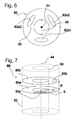
- FIG. 6 shows the schematic representation of an annular disc 80, with an outer diameter d5, an inner diameter d3, a center mr and three openings 82, wherein only one opening may be sufficient.
- the inner diameter d3 of the annular disc 80 is adapted to the outer diameter of the inner tube 30.
- the annular disc 80 similar to the above-described partial ring disc 76, can be fastened to the inner tube 30. However, this attachment preferably takes place in an orthogonal plane of the longitudinal axis 44.
- the outer diameter d5 of the annular disc 80 is preferably matched to the inner diameter da of the outer tube 32.
- the annular disc 80 thereby acts as a spacer between the outer tube 32 and the inner tube 30 and on the other hand, the vertical flow of the heat transfer fluid, in particular in the vicinity of the outer tube inner surface 60, thereby interrupted.
- the heat transfer fluid flows through the three orifice 82, thereby mixing the heat transfer fluid.
- FIG. 7 shows a schematic representation of an advantageous combination of two about the longitudinal axis 44 to each other rotated annular discs 80a and 80b, which are mutually, with a distance a in the direction of the longitudinal axis 44, respectively.
- Such an arrangement forms an annular disk pair 86.
- the present invention is not limited to the embodiment described above.
- the fastening of the annular disks 80 and / or the partial annular disks 76 can alternatively or additionally also take place on the outer pipe inner surface 60 of the outer pipe 32.
- the Operaringin 76 and / or the annular discs 80 then complete or partial distances from the inner tube 30 so that between them heat transfer fluid can flow in the axial direction.
- a helix which preferably has holes. The holes then generate the splitting of the rotary flow into a rotational and a vertical portion.
- stoppers 84 may be mounted on the part-disk turbulators. These generate additional turbulences of the oblique-rotational flow.
Landscapes
- Engineering & Computer Science (AREA)
- Life Sciences & Earth Sciences (AREA)
- Combustion & Propulsion (AREA)
- Sustainable Development (AREA)
- Sustainable Energy (AREA)
- Chemical & Material Sciences (AREA)
- General Life Sciences & Earth Sciences (AREA)
- Mechanical Engineering (AREA)
- General Engineering & Computer Science (AREA)
- Heat-Exchange Devices With Radiators And Conduit Assemblies (AREA)
- Geophysics And Detection Of Objects (AREA)
- Investigating Or Analyzing Materials By The Use Of Magnetic Means (AREA)
- Buildings Adapted To Withstand Abnormal External Influences (AREA)
- Investigating Or Analyzing Materials By The Use Of Ultrasonic Waves (AREA)
Abstract
Description
Die Erfindung betrifft einen Erdsondenfluidturbolator für eine koaxiale Erdsonde, welche zum Austausch von Wärme zwischen einem Wärmeübertragungsfluids und dem die Erdsonde umgebenen Erdreich, in welchem die Erdsonde im Betriebszustand angeordnet ist, vorgesehen ist.The invention relates to a geothermal fluid turbulator for a coaxial earth probe, which is provided for the exchange of heat between a heat transfer fluid and the soil surrounding the geothermal probe, in which the geothermal probe is arranged in the operating state.
Erdsonden können koaxial oder U-förmig aufgebaut sein. U-förmige Erdsonden weisen ein Einströmrohr auf, das in das Erdreich hinabführt und an einem unteren Ende in einem Verbindungsbereich fluidleitend mit einem Ausströmrohr verbunden ist. Das Wärmeübertragungsfluid strömt also das Einströmrohr hinab, geht in dem Verbindungsbereich in das Ausströmrohr über und strömt in diesem wieder hinauf. In koaxialen Erdsonden ist das Einströmrohr ein Außenrohr und das Ausströmrohr ein innerhalb des Außenrohres angeordnetes Innenrohr. Außerhalb des Innenrohres und innerhalb des Außenrohres ist ein Ringbereich, der einen Wärmeübertragungsbereich ausbildet. Die Anordnung des Außenrohres zum Innenrohr ist dabei koaxial. Der Verbindungsbereich ist bei einer koaxialen Erdsonde durch eine Öffnung des Innenrohres gebildet, so dass in dem Außenrohr bzw. im Ringbereich befindliches Wärmeübertragungsfluid hier in das Innenrohr fließen kann. Ein solches System ist in
Beim Durchlaufen der Erdsonde findet eine Wärmeübertragung zwischen dem Wärmeübertragungsfluid und dem Erdreich statt. Die Wärmeübertragung erfolgt im Wesentlichen durch Konvektion. Ob Wärme abgegeben oder aufgenommen wird hängt davon ab, ob die Erdsonde für einen Kälteprozess oder einem Wärmeprozess verwendet wird. Dazu werden gattungsgemäße Erdsonden bis zu 100 m tief im Erdreich angeordnet, in Einzelfällen werden auch größere Tiefen realisiert.When passing through the geothermal probe, heat transfer between the heat transfer fluid and the soil takes place. The heat transfer is essentially by convection. Whether heat is emitted or absorbed depends on whether the ground probe is used for a cooling process or a heat process. For this purpose, geological probes are arranged up to 100 m deep in the ground, in individual cases, larger depths are realized.
Üblicherweise werden mehrere Erdsonden in einem Erdsondenwärmekreislauf gemeinsam verwendet. Ein solcher Erdsondenwärmekreislauf weist meist eine Pumpe und einen Wärmetauscher auf. Mittels der Pumpe wird Wärmeübertragungsfluid zur Zirkulation innerhalb des Erdsondenwärmekreislaufes gebracht. Die Erdsonden können dabei parallel oder in Reihe oder in Kombinationen daraus geschaltet sein. Im Wärmetauscher wird die gewonnene Temperaturdifferenz zwischen dem zu- und dem abgeleiteten Wärmeübertragungsfluid an einen zweiten Fluidkreislauf übertragen.Typically, multiple ground probes are shared in a geothermal heat loop. Such a Erdsondenwärmekreislauf usually has a Pump and a heat exchanger. By means of the pump, heat transfer fluid is circulated within the ground probe heat circuit. The ground probes can be connected in parallel or in series or in combinations thereof. In the heat exchanger, the obtained temperature difference between the inlet and the derived heat transfer fluid is transferred to a second fluid circuit.
Der Temperaturunterschied zwischen dem in die Erdsonde eingeleiteten und abgeleiteten Wärmeübertragungsfluid wird im Folgenden als Temperaturgradient bezeichnet. Dem Erdreich wird ein Wärmestrom oder eine Wärmeleistung entnommen.The temperature difference between the heat transfer fluid introduced and discharged into the geothermal probe is referred to below as the temperature gradient. The soil is taken from a heat flow or a heat output.
Bei Erdsonden von weniger als 100 m Länge bzw. Tiefe beträgt der Temperaturunterschied zwischen dem eingeleiteten Wärmeübertragungsfluid und dem abgeleiteten Wärmeübertragungsfluid in der Regel wenige Grad. Üblich sind Einleitwerte zwischen -2 °C und 1 °C und Ausleitwerte zwischen 2 °C und 5 °C. Die Temperaturdifferenz ist verhältnismäßig gering und das aus den Erdsonden austretende Wärmeübertragungsfluid noch nicht zum Heizen von z.B. Wohnräumen geeignet. Die Wärmeleistung kann jedoch mit Hilfe einer Wärmepumpe nutzbar gemacht werden.For geothermal probes less than 100 meters in length or depth, the temperature difference between the heat transfer fluid introduced and the heat transfer fluid removed is typically a few degrees. Typical values are between -2 ° C and 1 ° C and conductance values between 2 ° C and 5 ° C. The temperature difference is relatively low and the heat transfer fluid exiting the geothermal probes is not yet ready to heat e.g. Residential spaces suitable. However, the heat output can be harnessed by means of a heat pump.
Üblicherweise kommen in einem Erdsondenwärmekreislauf mehrere Erdsonden zum Einsatz, da der nutzbare Temperaturunterschied einer Erdsonde in der Regel nicht ausreicht, um ein Wärmemittel in einem zweiten Fluidkreislauf in der Wärmepume zu verdampfen. Insbesondere bei Erdsonden mit einer Länge von unter 70 m ist der erzielbare Temperaturgradient häufig unzureichend. Weiterhin ist in einigen Regionen die zulässige Bohrtiefe begrenzt, um beispielsweise das Grundwasser zu schützen.Usually, a plurality of ground probes are used in a geothermal probe circuit, since the usable temperature difference of a geothermal probe is usually not sufficient to evaporate a heat medium in a second fluid circuit in the heat pump. Especially for ground probes with a length of less than 70 m, the achievable temperature gradient is often insufficient. Furthermore, in some regions, the permitted depth is limited, for example, to protect the groundwater.
Hier setzt nun die Erfindung ein. Sie hat es sich zur Aufgabe gemacht, den Wirkungsgrad von koaxialen Erdsonden und somit die Effizienz von koaxialen Erdsondenwärmekreisläufen zu verbessern. Weiterhin soll die Erfindung den effektiven Gebrauch von Erdsonden in Regionen ermöglichen, in denen Gesetze die zulässige Bohrtiefe begrenzen.This is where the invention begins. It has set itself the task to improve the efficiency of coaxial ground probes and thus the efficiency of coaxial Erdsondenwärmekreisläufen. Furthermore, the invention is to enable the effective use of geothermal probes in regions where laws limit the allowable drilling depth.
Ein erfindungsgemäß ausgestalteter Erdsondenfluidturbolator ist in einer koaxialen Erdsonde in einem Innenbereich eines Außenrohrs angeordnet und ist gekennzeichnet durch mindestens eine Teilringscheibe, die in einer Ebene liegt, die vorzugsweise in einem Winkel zu einer Orthogonalebene einer Längsachse der Erdsonde angeordnet ist, aufweisend einen Mittelpunkt, der etwa auf der Längsachse liegt, einen Innenrand, der zur Befestigung der Teilringscheibe an einem Innenrohr dient und einen Außendurchmesser, der kleiner gleich einem Innendurchmesser des Außenrohrs der Erdsonde ist. Der Mittelpunkt und der Außendurchmesser der Teilringscheibe sind definiert als Mittelpunkt und Außendurchmesser einer geschlossenen Ringscheibe, aus welcher die Teilringscheibe durch Ausschneiden eines Sektors entstehen würde.An invented Erdsondenfluidturbolator is arranged in a coaxial probe in an inner region of an outer tube and is characterized by at least one partial ring disc, which lies in a plane which is preferably arranged at an angle to an orthogonal plane of a longitudinal axis of the probe, having a center which is approximately is located on the longitudinal axis, an inner edge, which serves for fastening the partial annular disc to an inner tube and an outer diameter which is smaller than an inner diameter of the outer tube of the ground probe. The center point and the outer diameter of the partial annular disk are defined as the center point and outer diameter of a closed annular disk, from which the partial annular disk would be produced by cutting out a sector.
Durch das Vorsehen eines Erdsondenfluidturbolators kann die notwendige Länge einer Erdsonde, die erforderlich ist, damit die Erdsonde einen ausreichend großen Wirkungsgrad erreicht, reduziert werden und die Erdsonde kann auch in Regionen eingesetzt werden, in denen die Bohrtiefe geologisch oder gesetzlich begrenzt ist. Der Wirkungsgrad wird durch Verwirbelung des abseits des Erdsondenfluidturbolators annähernd laminar strömenden Wärmeübertragungsfluids erreicht.By providing a geothermal fluid turbulator, the necessary length of geothermal probe required for the geothermal probe to achieve sufficiently high efficiency can be reduced, and the geothermal probe can also be used in regions where the drilling depth is geologically or legally limited. Efficiency is achieved by turbulence of the heat transfer fluid flowing approximately laminar away from the earth probe fluid turbulator.
Als Wärmeübertragungsfluid wird üblicherweise Wasser verwendet. Da insbesondere in den kalten Wintermonaten auch Temperaturen unterhalb des Nullpunktes auftreten können, wird üblicherweise ein Frostschutz zugesetzt. Bedingt u.a. durch die Anomalie des Wassers ändern sich seine Stoffeigenschaften mit der Temperatur. So ist z.B. die Dichte von Wasser bei 4°C über Null am höchsten. Die Änderung der Stoffeigenschaften des Wassers führt in Erdsonden, in denen kein Erdsondenfluidturbolator angeordnet ist, dazu, dass sich eine annähernd laminare Strömung mit ungleich temperierten Schichten ausbildet. Die ungleich temperierten Schichten verlaufen parallel zu einer Außenrohraußenfläche, wobei in der Nähe der Außenrohrinnenfläche wärmere Schichten vorliegen, welche als Isolatoren der inneren Schichten wirken. Diese inneren Schichten nehmen daher kaum Wärme auf. Durch das Verwirbeln des Wärmeübertragungsfluids wird diese Schichtenbildung aufgehoben und dadurch ein höherer Temparaturgradient erzielt.As the heat transfer fluid, water is usually used. Since temperatures can also occur below zero in the cold winter months, frost protection is usually added. Due in part to the anomaly of the water, its material properties change with temperature. For example, the density of water is highest at 4 ° C above zero. The change in the material properties of the water leads in geothermal probes, in which no Erdsondenfluidturbolator is arranged, that forms an approximately laminar flow with unequal tempered layers. The unevenly tempered layers are parallel to an outer tube outer surface, wherein in the vicinity of the outer tube inner surface warmer layers are present, which act as insulators of the inner layers. These inner layers therefore absorb little heat. By swirling the heat transfer fluid, this layer formation is canceled, thereby achieving a higher Temparaturgradient.
Der durch die turbulente Strömung erhöhte Flußwiderstand ist nicht gravierend. Um beispielsweise drei hintereinander geschaltete Erdsonden mit 10 bis 14 Kubikmeter Wasser die Stunde zu durchfluten, reicht ein Druckunterschied von 0,1 bar bis 0,3 bar, so dass eine Pumpe lediglich 100 W bis 300 W an Leistung aufnehmen muss, um den Druckunterschied bereitzustellen.The increased by the turbulent flow flow resistance is not serious. For example, to penetrate three consecutive probes with 10 to 14 cubic meters of water per hour, a pressure difference of 0.1 bar to 0.3 bar, so that a pump only needs to absorb 100 W to 300 W of power to provide the pressure difference ,
Eine Teilringscheibe sorgt für unterschiedliche Strömungsrichtungen und ein dadurch verursachtes Verwirbeln des Wärmeübertragungsfluids. Oberhalb des Erdsondenfluidturbolators strömt das Wärmeübertragungsfluid nahezu laminar durch das Außenrohr. Beim Auftreffen auf eine Teilringscheibe erfährt das Wärmeübertragungsfluid, durch die Neigung der Teilringscheibe bezüglich der Orthogonalebene, eine Richtungsänderung und strömt alsdann entlang der Teilringscheibe schräg-rotatorisch durch das Außenrohr. Falls der Außendurchmesser der Teilringscheibe kleiner als der Innendurchmesser des Außenrohrs ist, wird der Fluidstrom in zwei Teilströme aufgeteilt: der bereits beschriebene, schräg-rotatorische und ein axialer zwischen eier Außenrohrinnenfläche und der Teilringscheibe. Die Aufteilung bewirkt zusätzliches Verwirbeln des Wärmeübertragungsfluids.A partial ring disc provides for different flow directions and thereby causing swirling of the heat transfer fluid. Above the ground probe fluid turbulator, the heat transfer fluid flows almost laminar through the outer tube. When impinging on a partial ring disk, the heat transfer fluid undergoes a change in direction due to the inclination of the partial annular disk with respect to the orthogonal plane and then flows obliquely and rotationally through the outer tube along the partial annular disk. If the outer diameter of the partial annular disc is smaller than the inner diameter of the outer tube, the fluid flow is divided into two partial flows: the previously described, obliquely rotational and an axial between egg outer tube inner surface and the partial annular disc. The division causes additional swirling of the heat transfer fluid.
Vorzugsweise werden mindestens zwei Teilringscheiben entlang der Längsachse benachbart zueinander angeordnet und weisen bezüglich der Orthogonalebene Winkelwerte mit unterschiedlichen Vorzeichen auf. Eine solche Anordnung ähnelt einer Helix, wenn die Winkelwerte in etwa gleiche Beträge aufweisen und die Teilringscheiben einander im Wesentlichen diametral gegenüberliegend, aber entlang der Längsachse versetzt zueinander angeordnet sind. Durch diese Geometrie wird die rotatorische Strömung gefördert.Preferably, at least two partial ring disks are arranged adjacent to one another along the longitudinal axis and have angle values with different signs with respect to the orthogonal plane. Such an arrangement resembles a helix when the angular values have approximately equal magnitudes and the partial annular discs are arranged substantially diametrically opposite one another but offset from one another along the longitudinal axis. This geometry promotes the rotary flow.
Zusätzlich können die Teilringscheiben eine oder mehrere Aussparungen aufweisen, durch die ein weiterer Teilstrom erreicht wird. Dieser spaltet sich von der schräg-rotatorischen Strömung ab und strömt durch die Aussparungen, also in etwa parallel zur Längsachse, hindurch. Die Form der Aussparungen ist dabei im Wesentlichen frei wählbar. Es eignen sich jedoch runde, elliptische, nierenförmige oder ringsektorische Aussparungen.In addition, the partial ring discs may have one or more recesses through which a further partial flow is achieved. This splits off from the oblique-rotational flow and flows through the recesses, that is approximately parallel to the longitudinal axis, through. The shape of the recesses is essentially arbitrary. However, round, elliptical, kidney-shaped or ring-sectoral recesses are suitable.
Vorzugsweise umschließen zwei benachbarte Teilringscheiben das Innenrohr gemeinsam um weniger als 360° und drei benachbarte Teilringscheiben das Innenrohr gemeinsam um mehr als 360°. Durch eine solche geometrische Anordnung soll eine zusätzliche Strömungsrichtung erreicht werden: die rotatorischen Strömungsrichtung soll sich dadurch zusätzlich aufteilen und einerseits rotatorisch bleiben, und andererseits axial zwischen den Teilringscheiben verlaufen. Ein zusätzliches Vermischen wird dadurch erreicht.Preferably, two adjacent partial annular disks jointly surround the inner pipe by less than 360 ° and three adjacent partial annular disks jointly enclose the inner pipe by more than 360 °. By means of such a geometric arrangement, an additional flow direction is to be achieved: the rotational flow direction is thereby to be additionally divided and, on the one hand, to remain rotational, and, on the other hand, to extend axially between the partial ring disks. An additional mixing is achieved.
Vorzugsweise bilden mindestens drei entlang der Längsachse zueinander angeordnete Teilringscheiben einen Teilscheibenturbulator. In einer besonders vorteilhaften Gestaltung weist dieser mindestens fünf Teilringscheiben auf. Davon weisen vorteilhafterweise mindestens drei Teilringscheiben einen Mittelpunktwinkel von etwa 180° auf und erweisen sich so als halbe Ringscheiben. Die restlichen Teilringscheiben weisen vorteilhafterweise einen Mittelpunktwinkel von etwa 160° bis 170° auf. Sie können also aus den Teilringscheiben mit Mittelpunktwinkel von etwa 180° dadurch hergestellt werden, dass von diesen Teilringscheiben Ringscheibensektoren von etwa 10° bis 30° an einem ihrer Enden entfernt werden.Preferably, at least three partial annular disks arranged along the longitudinal axis form a partial disk turbulator. In a particularly advantageous embodiment, this has at least five partial annular discs. Of these, advantageously, at least three partial annular discs have a central angle of about 180 ° and thus prove to be half annular discs. The remaining partial annular discs advantageously have a center angle of about 160 ° to 170 °. They can therefore be made of the partial annular discs with a center angle of about 180 °, characterized in that annular disc sectors of about 10 ° to 30 ° are removed at one of its ends of these part ring discs.
Ein Verfahren zum Herstellen einer Teilringscheibe ist dadurch gekennzeichnet, dass eine Platte, vorzugsweise aus thermoplastischem Kunststoff, die mittig ein rundes Loch aufweist, etwa in zwei gleiche Hälften getrennt wird und von welchen Hälften gegebenenfalls endseitig Ringsektoren abgetrennt werden.A method for producing a partial annular disk is characterized in that a plate, preferably made of thermoplastic material, which has a round hole in the center, is separated approximately into two equal halves, and from which halves optionally ring sectors are cut off at the end.
Vorzugsweise werden mindestens zwei Teilscheibenturbolatoren verwendet, deren jeweils oberste Teilringscheiben in Ebenen angeordnet sind, die bezüglich der Orthogonalebene in etwa gleiche Winkelwerte, aber mit unterschiedlichen Vorzeichen aufweisen. Dadurch wird erreicht, dass die rotatorische Strömung mindestens einmal im Uhrzeigersinn und mindestens einmal gegen den Uhrzeigersinn verläuft.Preferably, at least two partial disc turbulators are used, the respective uppermost annular discs are arranged in planes having approximately the same angle values with respect to the orthogonal plane, but with different signs. This ensures that the rotational flow is at least once clockwise and at least once counterclockwise.
Vorzugsweise beinhaltet der Erdsondenturbolator zusätzlich mindestens eine Ringscheibe mit einer Ringscheibenfläche, die sich vorzugsweise parallel zur Orthogonalebene erstreckt und mindestens eine Öffnung in der Ringscheibenfläche aufweist. Die Ringscheibe ist ans Innenrohr befestigt und umgibt dieses, wodurch eine Ringfläche zwischen dem Innenrohr und dem Außenrohr bis auf die Öffnungen der Ringscheibe weitestgehend geschlossen ist. Die Ringscheibe weist also einen Mittelpunkt auf, der etwa auf der Längsachse liegt, einen Innendurchmesser, der gleich einem Außendurchmesser des Innenrohrs ist und einen Außendurchmesser der kleiner gleich dem Innendurchmesser des Außenrohrs ist. Bei einer besonders vorteilhaften Gestaltung dieser Ringscheibe sind ihr Außendurchmesser und der Innendurchmesser des Außenrohrs gleich und stützt dieses. Die Ringscheibe erhöht somit die Stabilität der Erdsonde und schränkt die axiale Strömung entlang des Außenrohrs ein. Die Form und Anzahl der Öffnungen ist dabei im Wesentlichen frei wählbar. Es eignen sich jedoch drei oder vier runde oder nierenförmige Öffnungen.Preferably, the earth probe turbulizer additionally includes at least one annular disc having an annular disc surface which preferably extends parallel to the orthogonal plane and has at least one opening in the annular disc surface. The annular disc is attached to the inner tube and surrounds this, whereby an annular surface between the inner tube and the outer tube is largely closed except for the openings of the annular disc. The annular disc thus has a center which lies approximately on the longitudinal axis, an inner diameter which is equal to an outer diameter of the inner tube and an outer diameter which is less than or equal to the inner diameter of the outer tube. In a particularly advantageous design of this washer, its outer diameter and the inner diameter of the outer tube are the same and supports this. The annular disc thus increases the stability of the geothermal probe and limits the axial flow along the outer tube. The shape and number of openings is essentially freely selectable. However, there are three or four round or kidney-shaped openings.
Vorzugsweise bilden zwei Ringscheiben, die einen Abstand a entlang der Längsachse aufweisen und deren Öffnungen um einen Ringscheibenwinkel um die Längsachse verdreht zueinander angeordnet sind, ein Ringscheibenpaar. Dieser Ringscheibenwinkel sollte vorteilhafterweise so gewählt werden, dass in einer Draufsicht die Öffnungen der unteren Ringscheibe von der Ringscheibenfläche der oberen Ringscheibe zu mindestens teilweise verdeckt sind. Eine solche Anordnung bewirkt, dass das Wärmeübertragungsfluid keine rein translatorische Flußrichtugn zwischen den beiden Ringscheiben, sondern auch rotatorisch strömen muss. Dies fördert den Vermischungsprozess zusätzlich.Preferably, two annular discs, which have a distance a along the longitudinal axis and whose openings are rotated around an annular disc angle about the longitudinal axis to each other, form an annular disc pair. This annular disc angle should advantageously be chosen so that in a plan view, the openings of the lower annular disc of the annular disc surface of the upper annular disc are at least partially obscured. Such an arrangement causes the heat transfer fluid does not have to flow purely translational Flußrichtugn between the two annular discs, but also rotationally. This additionally promotes the mixing process.
Vorzugsweise weist eine Erdsonde auf Längenabschnitten von etwa 20m bis etwa 25m mindestens zehn Teilscheibenturbolatoren und mindestens zwei Ringscheibenpaare auf, so angeordnet, dass oberhalb, zwischen und unterhalb der Ringscheibenpaare Teilscheibenturbolatoren vorgesehen sind. Dadurch wird auf diesen Längenabschnitten ein gemeinsames Verwirbeln und Vermischen des Wärmeübertragungsfluids erreicht.Preferably, a ground probe on length sections of about 20m to about 25m at least ten Teilscheibeurburbolatoren and at least two annular disc pairs, arranged so that above, between and below the pairs of annular disc Teilscheibenturbolatoren are provided. As a result, a common swirling and mixing of the heat transfer fluid is achieved on these lengths.
Das Verwirbeln wird in erster Linie durch die Teilscheibenturbolatoren erreicht, in denen sich das Wärmeübertragungsfluid mehrfach in die drei oben beschriebenen Teilströme aufteilt und anschließend wieder vermengt. Diese Prozesse bewirken hauptsächlich ein Verwirbeln des Wärmeübertragungsfluids, welches zusätzlich durch Rotationsrichtungsänderungen zweier entlang der Längsachse zueinander benachbart angeordneter Teilringscheiben verstärkt wird. Dieser Verwirbelungsprozess wird durch Vermischungsprozesse mehrerer Ringscheibenpaare unterstützt.The swirling is achieved primarily by the Teilscheibenturbolatoren, in which the heat transfer fluid is divided several times in the three partial streams described above and then mixed again. These processes mainly cause swirling of the heat transfer fluid, which in addition is amplified by rotational direction changes of two along the longitudinal axis adjacent to each other arranged part ring discs. This turbulence process is supported by mixing processes of several pairs of annular disks.
Vorteilhafte Ausgestaltungen der Erfindung sind jeweils Gegenstand der abhängigen Ansprüche. Es wird darauf hingewiesen, dass die in den Patentansprüchen einzeln aufgeführten Merkmale in beliebiger, technologisch sinnvoller Weise miteinander kombiniert werden können und weitere Ausgestaltungen der Erfindung aufzeigen. Die Beschreibung, insbesondere im Zusammenhang mit den Figuren, charakterisiert und spezifiziert die Erfindung zusätzlich.Advantageous embodiments of the invention are each the subject of the dependent claims. It should be noted that the features listed individually in the claims can be combined with each other in any technologically meaningful manner and show further embodiments of the invention. The description, in particular in connection with the figures, additionally characterizes and specifies the invention.
Weitere Vorteile und Merkmale der Erfindung werden in der nun folgenden Figurenbeschreibung beschrieben. In dieser zeigen:
- Fig. 1:
- eine schematische Darstellung einer Erdsonde mit einem Anschlussdeckel, einem Innenrohr und einem Außenrohr, wobei um das Innenrohr Mittel zur Verwirbelung des Wärmeübertragungsfluids angeordnet sind,
- Fig. 2:
- eine schematische Darstellung eines Erdsondenwärmekreislaufes mit mehreren Erdsonden, die in Reihe geschaltet sind,
- Fig. 3
- die Darstellung eines Erdsondenwärmekreislaufes aus
Figur 2 in einer Seitenansicht mit in Erdreich angeordneten Erdsonden, die über Leitungen mit einem Wärmetauscher und einer Pumpe verbunden sind, wobei die Erdsonden in Reihe geschaltet sind, - Fig. 4
- die schematische Darstellung einer beispielhaften Teilringscheibe,
- Fig. 5
- die schematische Darstellung eines Teilscheibenturbolators montiert in einer koaxialen Erdsonde und die dadurch verursachten Flussrichtungen des Wärmeübertragungsfluids,
- Fig. 6
- die schematische Darstellung einer Ringscheibe mit Öffnungen, und
- Fig. 7
- die schematische Darstellung eines Ringscheibenpaars.
- Fig. 1:
- a schematic representation of a ground probe with a connection cover, an inner tube and an outer tube, wherein means are arranged around the inner tube for swirling the heat transfer fluid,
- Fig. 2:
- a schematic representation of a Erdsondenwärmekreislaufes with multiple ground probes, which are connected in series,
- Fig. 3
- the representation of a Erdsondenwärmekreislaufes
FIG. 2 in a side view with earth probes arranged in soil, which are connected via lines to a heat exchanger and a pump, wherein the ground probes are connected in series, - Fig. 4
- the schematic representation of an exemplary partial annular disc,
- Fig. 5
- the schematic representation of a Partscheubenturbolators mounted in a coaxial earth probe and the resulting flow directions of the heat transfer fluid,
- Fig. 6
- the schematic representation of an annular disc with openings, and
- Fig. 7
- the schematic representation of an annular disc pair.
Bei der folgenden Beschreibung, sowohl des Teilscheibenturbolators, als auch des gesamten Erdsondenfluidturbolators, wird davon ausgegangen, dass die Erdsonde in vertikaler Richtung montiert wird. Bei schräger Montage der Erdsonde können sich die Lagen der einzelnen Komponenten zueinander ändern.In the following description, both the Particle Turbinator and the entire Earth Probe Fluid Turbulator, it will be assumed that the ground probe is mounted in the vertical direction. If the probe is mounted at an angle, the positions of the individual components may change.
Am oberen Ende 72 ist an dem Außenrohr 32 ein Anschlussdeckel 24 angeordnet. Darin ist der Zulauf 22 fluidleitend mit dem Ringraum 64 und der Ablauf 40 fluidleitend mit dem Innenrohrinnenraum 66 verbunden. Der Anschlussdecke 24 bildet die Schnittstelle zwischen dem Teil der Erdsonde 20, der sich im Erdreich 54 befindet und dem Teil, der von außen zugänglich ist. Vorteilhafterweise weisen sowohl der Zulauf 22 als auch der Ablauf 40 Mittel zur Befestigung von Leitungen auf. In einer sehr einfachen Ausgestaltung ist der Anschlussdeckel 24 auf das Außenrohr 32 gesteckt und abgedichtet. Der gezeigte Anschlussdeckel 23 weist eine Heizwendel 34 auf, die aus einem elektrischen Leiter gebildet wird. Über Anschlußkontakte 28 kann ein Strom durch die Heizwendel 34 geleitet werden, um die Heizwendel 34 zu erhitzen, wodurch der Anschlussdeckel 24 mit dem Außenrohr 32 verschweißt werden kann.At the
Die Erdsonde 20 weist eine Länge L auf, die entsprechend der erwünschten Tiefe variiert, beispielsweise zwischen 15m und 25 m. Das Wärmeübertragungsfluid nimmt während des Durchströmens des Ringraumes 64 eine Wärmeleistung aus dem Erdreich 54 auf. Das Außenrohr 32 ist dazu vorteilhafterweise aus einem Material gefertigt, welches eine verhältnismäßig hohen Wärmeübertragungskoeffizienten aufweist. Beispielsweise kann Highdensity-Polyethylen, kurz PE-HD verwendet werden. Das Wärmeübertragungsfluid steigt anschließend mit einer höheren Temperatur innerhalb des Innenrohres 30 wieder empor.The
In einem unteren Ende 74 der Erdsonde 20 ist ein Sondenfuß 46 angeordnet, der konisch spitz zuläuft. Dieser Sondenfuß 46 erleichtert das Eindringen der Erdsonde 20 in eine Bohrung. Der Sondenfuß 46 kann mittels eines thermischen Schweißverfahrens, beispielsweise Stumpfscheißen, mit dem Außenrohr 32 verbunden werden.In a
Das Außenrohr 32 weist üblicherweise eine Wandstärke wa zwischen 2,5 mm und 5 mm auf. Vorzugsweise weist es eine Wandstärke wa von 3,2 mm bis 3,8 mm auf. Der innere Durchmesser des Außenrohres 32 beträgt vorzugsweise 100 mm bis 180 mm. Der innere Durchmesser di des Innenrohres 30 liegt vorteilhaft zwischen 20 mm und 50 mm. Das Verhältnis des Durchmessers di des Innenrohres 30 zu dem Durchmesser da des Außenrohres 32 liegt also in einem Bereich zwischen 0,2 und 0,7, vorteilhaft in einem Bereich zwischen 0,25 und 0,35. Dadurch wird erreicht, dass der Ringraum 64 eine verhältnismäßig große Fläche aufweist und sich das Wärmeübertragungsfluid darin möglichst langsam bewegt. Gleichzeitig ist noch gewährleistet, dass der Durchmesser di des Innenrohres 30 nicht zu klein ist und sich hier kein zu großer Rohrwiderstand ausbildet.The
Um die Erdsonde 20 entlüften zu können, weist die erfindungsgemäße Erdsonde 20 vorteilhaft eine Entlüftung 70 auf. Diese umfasst eine Entlüftungsöffnung 42, eine Entlüftungsleitung 36 und ein Entlüftungsventil 38. Die Entlüftungsöffnung 42 ist vorteilhaft an einer möglichst weit oben gelegenen Stelle des Anschlussdeckels 24 angeordnet. Die Entlüftungsleitung 36 ist an die Entlüftungsöffnung 42 angeschlossen. Am anderen Ende der Entlüftungsleitung 36 ist ein Entlüftungsventil 38 angeordnet, beispielsweise ein Kugelhahn. Zur Entlüftung der Erdsonde 20 wird das Wärmeübertragungsfluid unter Druck gesetzt und das Entlüftungsventil 38 geöffnet.To be able to vent the
Der Außendurchmesser d1 der Teilringscheibe 76 ist so gewählt, dass er geringfügig kleiner als der Innendurchmesser des Außenrohrs 32 ist. Einerseits wird dadurch ein Einschieben des Innenrohrs 30 samt befestigten Teilringscheiben 76 in das Außenrohr 32 vereinfacht, andererseits wirken die Teilringscheiben 76 dadurch im Betriebszustand als Abstandshalter zwischen Außenrohr 32 und Innenrohr 30, beziehungsweise stützen die beiden gegeneinander ab.The outer diameter d1 of the partial annular disc 76 is selected to be slightly smaller than the inner diameter of the
Über einen Längenabschnitt von etwa 15m bis 25m empfiehlt sich eine Kombination von circa 10 bis 15 Teilscheibenturbulatoren 84 mit mindestens zwei Ringscheibenpaaren 86. Eine solche Kombination weist im obersten Bereich des Längenabschnitts einige Ringscheibenturbolatoren 84 auf, auf welche ein Ringscheibenpaar 86 folgt. Diese Anordnung wiederholt sich und wird im unteren Teil entweder durch einen Teilscheibenturbolator 84 oder durch ein Ringscheibenpaar 86 abgeschlossen. Ferner empfiehlt es sich, die erzeugte rotatorische Strömungsrichtung der Teilscheibenturbulatoren 84 abzuwechseln: wenn in einer Draufsicht ein erster Teilscheibenturbolator 84 eine rotatorische Bewegung des Wärmeübertragungsfluids im Uhrzeigersinn erzeugt, sollte mindestens ein zweiter Teilscheibenturbolator 84 eine rotatorische Bewegung entgegen des Uhrzeigersinns erzeugen. Teilscheibenturbolatoren 84 und/oder Ringscheibenpaare 86 können abschnittsweise oder über die gesamte Länge der Erdsonde 20 angeordnet sein.Over a length of about 15m to 25m, a combination of about 10 to 15
Durch das Vermischen und Verwirbeln des Wärmeübertragungsfluids durch die Kombination von Teilscheibenturbolatoren 84 und Ringscheibenpaaren 86 findet ein optimaler und harmonischer Energieaustausch zwischen Erdreich und Wärmeübertragungsfluid statt. Daraus resultiert, dass die Wärmepumpe schon bei geringen Bohrtiefen von 15m-30m hocheffiziente Wirkungsgrade erzielen. Offensichtliche Vorteile einer geringeren Bohrtiefe sind unter anderem die geringen Anschaffungs- und Installationskosten und die Verwendbarkeit von Wärmepumpen in Bereichen mit Bohrtiefenbegrenzung.By mixing and swirling the heat transfer fluid through the combination of
Die vorliegende Erfindung ist selbstverständlich nicht auf das vorstehend beschriebene Ausführungsbeispiel beschränkt. So kann die Befestigung der Ringscheiben 80 und/oder der Teilringscheiben 76 alternativ oder zusätzlich auch an der Außenrohrinnenfläche 60 des Außenrohrs 32 erfolgen. Im Falle einer ausschließlichen oder teilweisen Befestigung an der Außenrohrinnenfläche 60 des Außenrohrs 32 können die Teilringscheiben 76 und/oder die Ringscheiben 80 dann vollständige oder teilweise Abstände vom Innenrohr 30 aufweisen, so dass dazwischen Wärmeübertragungsfluid in axialer Richtung strömen kann.Of course, the present invention is not limited to the embodiment described above. Thus, the fastening of the
Anstelle eines Teilscheibenturbolators 84 kann für die Erzeugung der schräg, rotatorischen Bewegung des Wärmeübertragungsfluids eine Helix verwendet werden, die vorzugsweise Löcher aufweist. Die Löcher erzeugen dann die Aufspaltung der rotatorischen Strömung in einen rotatorischen und einen vertikalen Anteil.Instead of a Teilteilurburbenturbolators 84 can be used to generate the oblique, rotational movement of the heat transfer fluid, a helix, which preferably has holes. The holes then generate the splitting of the rotary flow into a rotational and a vertical portion.
Ferner können auf den Teilscheibenturbolatoren 84 Stopper angebracht sein. Diese erzeugen zusätzliche Verwirbelungen der schräg-rotatorische Strömung.Further,
- 20.20th
- ErdsondeErdsonde
- 22.22nd
- ZulaufIntake
- 24.24th
- Anschlussdeckelconnection cover
- 26.26th
- ErdsondenwärmekreislaufErdsondenwärmekreislauf
- 28.28th
- Anschlusskontaktconnection contact
- 30.30th
- Innenrohrinner tube
- 32.32nd
- Außenrohrouter tube
- 34.34th
- Heizwendelnheating coils
- 36.36th
- Entlüftungsleitungvent line
- 38.38th
- Entlüftungsventilvent valve
- 40.40th
- Ablaufprocedure
- 42.42nd
- Entlüftungsöffnungvent
- 44.44th
- Längsachselongitudinal axis
- 46.46th
- Sondenfußprobe base
- 48.48th
- Pumpepump
- 50.50th
- Wärmetauscherheat exchangers
- 52.52nd
- Leitungencables
- 54.54th
- Erdreichsoil
- 56.56th
- InnenrohrinnenflächeInner tube inner surface
- 58.58th
- InnenrohraußenflächeInner tube outer surface
- 60.60th
- AußenrohrinnenflächeOuter tube inner surface
- 62.62nd
- AußenrohraußenflächeOuter tube outer surface
- 64.64th
- Ringraumannulus
- 66.66th
- InnenrohrraumInner tube space
- 68.68th
- Verbindungsbereichconnecting area
- 70.70th
- Entlüftungvent
- 72.72nd
- unteres Endelower end
- 74.74th
- unteres Endelower end
- 76.76th
- TeilringscheibePart washer
- 78.78th
- Innenrandinner edge
- 80.80th
- Ringscheibewasher
- 82.82nd
- Öffnungopening
- 84.84th
- TeilscheibenturbolatorTeilscheibenturbolator
- 86.86th
- RingscheibenpaarWasher pair
- 88.88th
- Aussparungrecess
Claims (15)
Priority Applications (3)
| Application Number | Priority Date | Filing Date | Title |
|---|---|---|---|
| SI201130738T SI2360438T1 (en) | 2010-02-11 | 2011-02-11 | Fluid turbulator for geothermal probe |
| PL11154105T PL2360438T3 (en) | 2010-02-11 | 2011-02-11 | Fluid turbulator for geothermal probe |
| HRP20160160TT HRP20160160T1 (en) | 2010-02-11 | 2016-02-15 | Fluid turbulator for geothermal probe |
Applications Claiming Priority (1)
| Application Number | Priority Date | Filing Date | Title |
|---|---|---|---|
| DE102010001823A DE102010001823A1 (en) | 2010-02-11 | 2010-02-11 | Erdsondenfluidturbulator |
Publications (3)
| Publication Number | Publication Date |
|---|---|
| EP2360438A2 true EP2360438A2 (en) | 2011-08-24 |
| EP2360438A3 EP2360438A3 (en) | 2014-08-27 |
| EP2360438B1 EP2360438B1 (en) | 2016-02-10 |
Family
ID=43901264
Family Applications (1)
| Application Number | Title | Priority Date | Filing Date |
|---|---|---|---|
| EP11154105.8A Active EP2360438B1 (en) | 2010-02-11 | 2011-02-11 | Fluid turbulator for geothermal probe |
Country Status (8)
| Country | Link |
|---|---|
| EP (1) | EP2360438B1 (en) |
| DE (1) | DE102010001823A1 (en) |
| DK (1) | DK2360438T3 (en) |
| ES (1) | ES2563780T3 (en) |
| HR (1) | HRP20160160T1 (en) |
| PL (1) | PL2360438T3 (en) |
| RS (1) | RS54604B1 (en) |
| SI (1) | SI2360438T1 (en) |
Cited By (1)
| Publication number | Priority date | Publication date | Assignee | Title |
|---|---|---|---|---|
| WO2015044142A1 (en) * | 2013-09-24 | 2015-04-02 | Dynamic Blue Holding Gmbh | Geothermal probe with mixing elements |
Families Citing this family (3)
| Publication number | Priority date | Publication date | Assignee | Title |
|---|---|---|---|---|
| DE202014102027U1 (en) | 2014-04-30 | 2015-08-03 | Klaus Knof | Erdsonde |
| DE102016109063A1 (en) | 2016-05-17 | 2017-11-23 | Anton LEDWON | Geothermal probe and method for adjusting the length of a geothermal probe |
| DE102021108225A1 (en) * | 2021-03-31 | 2022-10-06 | Dynamic Blue Holding Gmbh | Flow control element for cold heating networks |
Citations (1)
| Publication number | Priority date | Publication date | Assignee | Title |
|---|---|---|---|---|
| DE102008002048A1 (en) | 2008-05-28 | 2009-12-10 | Koenig & Bauer Aktiengesellschaft | Cleaning system for cleaning e.g. plate cylinder of printing unit of printing machine, has cleaning unit for receiving contamination of printing element cylinders, and blowing device blowing contamination from printing element cylinders |
Family Cites Families (4)
| Publication number | Priority date | Publication date | Assignee | Title |
|---|---|---|---|---|
| DE3000157C2 (en) * | 1980-01-04 | 1984-05-17 | Klaus 3101 Hornbostel Prenzler | Heat exchanger device for extracting thermal energy from the ground |
| JP2004340463A (en) * | 2003-05-15 | 2004-12-02 | K & S Japan Kk | Air conditioner utilizing geothermal heat |
| EP2957841A1 (en) * | 2007-09-08 | 2015-12-23 | Dynamic Blue Holding GmbH | Geothermal heat exchanger circuit |
| DE202008012055U1 (en) * | 2008-08-06 | 2009-02-19 | Rausch Gmbh | Probe head and probe for exchanging heat energy |
-
2010
- 2010-02-11 DE DE102010001823A patent/DE102010001823A1/en not_active Ceased
-
2011
- 2011-02-11 RS RS20160084A patent/RS54604B1/en unknown
- 2011-02-11 SI SI201130738T patent/SI2360438T1/en unknown
- 2011-02-11 EP EP11154105.8A patent/EP2360438B1/en active Active
- 2011-02-11 ES ES11154105.8T patent/ES2563780T3/en active Active
- 2011-02-11 DK DK11154105.8T patent/DK2360438T3/en active
- 2011-02-11 PL PL11154105T patent/PL2360438T3/en unknown
-
2016
- 2016-02-15 HR HRP20160160TT patent/HRP20160160T1/en unknown
Patent Citations (1)
| Publication number | Priority date | Publication date | Assignee | Title |
|---|---|---|---|---|
| DE102008002048A1 (en) | 2008-05-28 | 2009-12-10 | Koenig & Bauer Aktiengesellschaft | Cleaning system for cleaning e.g. plate cylinder of printing unit of printing machine, has cleaning unit for receiving contamination of printing element cylinders, and blowing device blowing contamination from printing element cylinders |
Cited By (5)
| Publication number | Priority date | Publication date | Assignee | Title |
|---|---|---|---|---|
| WO2015044142A1 (en) * | 2013-09-24 | 2015-04-02 | Dynamic Blue Holding Gmbh | Geothermal probe with mixing elements |
| CN105579786A (en) * | 2013-09-24 | 2016-05-11 | 动力蓝控股公司 | Geothermal probe with mixing elements |
| US20160195304A1 (en) * | 2013-09-24 | 2016-07-07 | Dynamic Blue Holding Gmbh | Geothermal probe with mixing elements |
| JP2016537598A (en) * | 2013-09-24 | 2016-12-01 | ダイナミック ブルー ホールディング ゲーエムベーハーDynamic Blue Holding Gmbh | Geothermal probe with mixing element |
| US10113773B2 (en) * | 2013-09-24 | 2018-10-30 | Dynamic Blue Holding Gmbh | Geothermal probe with mixing elements |
Also Published As
| Publication number | Publication date |
|---|---|
| EP2360438B1 (en) | 2016-02-10 |
| RS54604B1 (en) | 2016-08-31 |
| DE102010001823A1 (en) | 2011-08-11 |
| HRP20160160T1 (en) | 2016-03-11 |
| ES2563780T3 (en) | 2016-03-16 |
| PL2360438T3 (en) | 2016-06-30 |
| EP2360438A3 (en) | 2014-08-27 |
| SI2360438T1 (en) | 2016-04-29 |
| DK2360438T3 (en) | 2016-04-18 |
Similar Documents
| Publication | Publication Date | Title |
|---|---|---|
| EP2360438B1 (en) | Fluid turbulator for geothermal probe | |
| EP2034252B1 (en) | Geothermal heat exchanger circuit | |
| EP3193117B1 (en) | Heat exchange device | |
| DE2748727A1 (en) | METHOD AND DEVICE FOR STORING THERMAL ENERGY, SUCH AS SOLAR HEAT, FOR EXAMPLE | |
| WO1990000707A1 (en) | Installation for energy exchange between the ground and an energy exchanger | |
| DE102005020887B3 (en) | Spiral filament heat exchanger for geothermal heat has outer and inner spirals held at spacing by one or more spacing tubes running perpendicularly | |
| EP2357424B1 (en) | Storage device for storing warm liquids at different temperatures | |
| DE102014113750B4 (en) | Storage probe with mixed bodies | |
| WO2014000852A1 (en) | Heat management system | |
| EP3748254B1 (en) | Geothermal heat exchanger assembly comprising heat exchanger screw posts | |
| EP2520872B1 (en) | Solar tower power plant - solar receiver | |
| DE19810713C2 (en) | Core drilling device, device for insertion into a crown tube and method for cooling a drilling site | |
| DE102010008710B4 (en) | Method for laying geothermal probes and geothermal probes | |
| CH710040A2 (en) | Insulating piping, using an insulating pipe, to processes for their preparation and geothermal probe. | |
| WO1995030863A1 (en) | Facility for effecting energy exchange between the ground and an energy exchanger | |
| EP0861985A2 (en) | Device for vertical temperature division of a fluid in an accumulator | |
| DE102010007662A1 (en) | Geothermal energy distributor for use with geothermal or ground probes, is formed of collecting body with two connecting pieces and connection opening, where connecting pieces are arranged along longitudinal axis of collecting body | |
| DE1800852A1 (en) | Filter line for pipe wells | |
| DE202012004408U1 (en) | Massive absorber in modular design | |
| WO2013091853A1 (en) | Geothermal probe assembly | |
| DE102010019728A1 (en) | Heat exchanger device, use, heat exchanger assembly | |
| DE10040940B4 (en) | Multi-stage water wheel | |
| DE202018005135U1 (en) | Device for underwater irrigation of tree roots | |
| EP4067670A1 (en) | Flow guiding element for cooling and heating networks | |
| EP3587956B1 (en) | Arrangement of earth collectors for large-scale plants in cold local heat usage |
Legal Events
| Date | Code | Title | Description |
|---|---|---|---|
| PUAI | Public reference made under article 153(3) epc to a published international application that has entered the european phase |
Free format text: ORIGINAL CODE: 0009012 |
|
| PUAI | Public reference made under article 153(3) epc to a published international application that has entered the european phase |
Free format text: ORIGINAL CODE: 0009012 |
|
| AK | Designated contracting states |
Kind code of ref document: A2 Designated state(s): AL AT BE BG CH CY CZ DE DK EE ES FI FR GB GR HR HU IE IS IT LI LT LU LV MC MK MT NL NO PL PT RO RS SE SI SK SM TR |
|
| AX | Request for extension of the european patent |
Extension state: BA ME |
|
| RIC1 | Information provided on ipc code assigned before grant |
Ipc: F24J 3/08 20060101AFI20140407BHEP |
|
| RAP1 | Party data changed (applicant data changed or rights of an application transferred) |
Owner name: DYNAMIC BLUE HOLDING GMBH |
|
| RIN1 | Information on inventor provided before grant (corrected) |
Inventor name: DYNAMIC BLUE HOLDING GMBH |
|
| PUAL | Search report despatched |
Free format text: ORIGINAL CODE: 0009013 |
|
| AK | Designated contracting states |
Kind code of ref document: A3 Designated state(s): AL AT BE BG CH CY CZ DE DK EE ES FI FR GB GR HR HU IE IS IT LI LT LU LV MC MK MT NL NO PL PT RO RS SE SI SK SM TR |
|
| AX | Request for extension of the european patent |
Extension state: BA ME |
|
| RIC1 | Information provided on ipc code assigned before grant |
Ipc: F24J 3/08 20060101AFI20140718BHEP |
|
| 17P | Request for examination filed |
Effective date: 20150226 |
|
| RBV | Designated contracting states (corrected) |
Designated state(s): AL AT BE BG CH CY CZ DE DK EE ES FI FR GB GR HR HU IE IS IT LI LT LU LV MC MK MT NL NO PL PT RO RS SE SI SK SM TR |
|
| GRAP | Despatch of communication of intention to grant a patent |
Free format text: ORIGINAL CODE: EPIDOSNIGR1 |
|
| INTG | Intention to grant announced |
Effective date: 20150730 |
|
| GRAS | Grant fee paid |
Free format text: ORIGINAL CODE: EPIDOSNIGR3 |
|
| GRAA | (expected) grant |
Free format text: ORIGINAL CODE: 0009210 |
|
| RIN1 | Information on inventor provided before grant (corrected) |
Inventor name: LEDWON, ANTON |
|
| AK | Designated contracting states |
Kind code of ref document: B1 Designated state(s): AL AT BE BG CH CY CZ DE DK EE ES FI FR GB GR HR HU IE IS IT LI LT LU LV MC MK MT NL NO PL PT RO RS SE SI SK SM TR |
|
| REG | Reference to a national code |
Ref country code: GB Ref legal event code: FG4D Free format text: NOT ENGLISH |
|
| REG | Reference to a national code |
Ref country code: HR Ref legal event code: TUEP Ref document number: P20160160 Country of ref document: HR Ref country code: AT Ref legal event code: REF Ref document number: 774856 Country of ref document: AT Kind code of ref document: T Effective date: 20160215 Ref country code: CH Ref legal event code: EP |
|
| REG | Reference to a national code |
Ref country code: RO Ref legal event code: EPE |
|
| REG | Reference to a national code |
Ref country code: SE Ref legal event code: TRGR |
|
| REG | Reference to a national code |
Ref country code: IE Ref legal event code: FG4D Free format text: LANGUAGE OF EP DOCUMENT: GERMAN |
|
| REG | Reference to a national code |
Ref country code: HR Ref legal event code: T1PR Ref document number: P20160160 Country of ref document: HR |
|
| REG | Reference to a national code |
Ref country code: ES Ref legal event code: FG2A Ref document number: 2563780 Country of ref document: ES Kind code of ref document: T3 Effective date: 20160316 |
|
| REG | Reference to a national code |
Ref country code: DE Ref legal event code: R096 Ref document number: 502011008832 Country of ref document: DE |
|
| REG | Reference to a national code |
Ref country code: FR Ref legal event code: PLFP Year of fee payment: 6 |
|
| REG | Reference to a national code |
Ref country code: NL Ref legal event code: FP |
|
| REG | Reference to a national code |
Ref country code: DK Ref legal event code: T3 Effective date: 20160411 |
|
| REG | Reference to a national code |
Ref country code: LT Ref legal event code: MG4D |
|
| PG25 | Lapsed in a contracting state [announced via postgrant information from national office to epo] |
Ref country code: GR Free format text: LAPSE BECAUSE OF FAILURE TO SUBMIT A TRANSLATION OF THE DESCRIPTION OR TO PAY THE FEE WITHIN THE PRESCRIBED TIME-LIMIT Effective date: 20160511 Ref country code: FI Free format text: LAPSE BECAUSE OF FAILURE TO SUBMIT A TRANSLATION OF THE DESCRIPTION OR TO PAY THE FEE WITHIN THE PRESCRIBED TIME-LIMIT Effective date: 20160210 Ref country code: NO Free format text: LAPSE BECAUSE OF FAILURE TO SUBMIT A TRANSLATION OF THE DESCRIPTION OR TO PAY THE FEE WITHIN THE PRESCRIBED TIME-LIMIT Effective date: 20160510 |
|
| PG25 | Lapsed in a contracting state [announced via postgrant information from national office to epo] |
Ref country code: PT Free format text: LAPSE BECAUSE OF FAILURE TO SUBMIT A TRANSLATION OF THE DESCRIPTION OR TO PAY THE FEE WITHIN THE PRESCRIBED TIME-LIMIT Effective date: 20160613 Ref country code: LT Free format text: LAPSE BECAUSE OF FAILURE TO SUBMIT A TRANSLATION OF THE DESCRIPTION OR TO PAY THE FEE WITHIN THE PRESCRIBED TIME-LIMIT Effective date: 20160210 Ref country code: IS Free format text: LAPSE BECAUSE OF FAILURE TO SUBMIT A TRANSLATION OF THE DESCRIPTION OR TO PAY THE FEE WITHIN THE PRESCRIBED TIME-LIMIT Effective date: 20160610 Ref country code: LV Free format text: LAPSE BECAUSE OF FAILURE TO SUBMIT A TRANSLATION OF THE DESCRIPTION OR TO PAY THE FEE WITHIN THE PRESCRIBED TIME-LIMIT Effective date: 20160210 |
|
| PG25 | Lapsed in a contracting state [announced via postgrant information from national office to epo] |
Ref country code: EE Free format text: LAPSE BECAUSE OF FAILURE TO SUBMIT A TRANSLATION OF THE DESCRIPTION OR TO PAY THE FEE WITHIN THE PRESCRIBED TIME-LIMIT Effective date: 20160210 |
|
| REG | Reference to a national code |
Ref country code: DE Ref legal event code: R097 Ref document number: 502011008832 Country of ref document: DE |
|
| PG25 | Lapsed in a contracting state [announced via postgrant information from national office to epo] |
Ref country code: SM Free format text: LAPSE BECAUSE OF FAILURE TO SUBMIT A TRANSLATION OF THE DESCRIPTION OR TO PAY THE FEE WITHIN THE PRESCRIBED TIME-LIMIT Effective date: 20160210 Ref country code: SK Free format text: LAPSE BECAUSE OF FAILURE TO SUBMIT A TRANSLATION OF THE DESCRIPTION OR TO PAY THE FEE WITHIN THE PRESCRIBED TIME-LIMIT Effective date: 20160210 |
|
| REG | Reference to a national code |
Ref country code: IE Ref legal event code: MM4A |
|
| PLBE | No opposition filed within time limit |
Free format text: ORIGINAL CODE: 0009261 |
|
| STAA | Information on the status of an ep patent application or granted ep patent |
Free format text: STATUS: NO OPPOSITION FILED WITHIN TIME LIMIT |
|
| 26N | No opposition filed |
Effective date: 20161111 |
|
| PG25 | Lapsed in a contracting state [announced via postgrant information from national office to epo] |
Ref country code: IE Free format text: LAPSE BECAUSE OF NON-PAYMENT OF DUE FEES Effective date: 20160211 |
|
| REG | Reference to a national code |
Ref country code: FR Ref legal event code: PLFP Year of fee payment: 7 |
|
| PG25 | Lapsed in a contracting state [announced via postgrant information from national office to epo] |
Ref country code: BG Free format text: LAPSE BECAUSE OF FAILURE TO SUBMIT A TRANSLATION OF THE DESCRIPTION OR TO PAY THE FEE WITHIN THE PRESCRIBED TIME-LIMIT Effective date: 20160510 |
|
| PGFP | Annual fee paid to national office [announced via postgrant information from national office to epo] |
Ref country code: DK Payment date: 20170222 Year of fee payment: 7 Ref country code: PL Payment date: 20170127 Year of fee payment: 7 Ref country code: NL Payment date: 20170220 Year of fee payment: 7 Ref country code: AT Payment date: 20170217 Year of fee payment: 7 Ref country code: BE Payment date: 20170220 Year of fee payment: 7 |
|
| PG25 | Lapsed in a contracting state [announced via postgrant information from national office to epo] |
Ref country code: MT Free format text: LAPSE BECAUSE OF FAILURE TO SUBMIT A TRANSLATION OF THE DESCRIPTION OR TO PAY THE FEE WITHIN THE PRESCRIBED TIME-LIMIT Effective date: 20160210 |
|
| REG | Reference to a national code |
Ref country code: DE Ref legal event code: R079 Ref document number: 502011008832 Country of ref document: DE Free format text: PREVIOUS MAIN CLASS: F24J0003080000 Ipc: F24T0010000000 |
|
| REG | Reference to a national code |
Ref country code: FR Ref legal event code: PLFP Year of fee payment: 8 |
|
| PGFP | Annual fee paid to national office [announced via postgrant information from national office to epo] |
Ref country code: CH Payment date: 20180221 Year of fee payment: 8 Ref country code: RO Payment date: 20180130 Year of fee payment: 8 |
|
| PG25 | Lapsed in a contracting state [announced via postgrant information from national office to epo] |
Ref country code: CY Free format text: LAPSE BECAUSE OF FAILURE TO SUBMIT A TRANSLATION OF THE DESCRIPTION OR TO PAY THE FEE WITHIN THE PRESCRIBED TIME-LIMIT Effective date: 20160210 Ref country code: HU Free format text: LAPSE BECAUSE OF FAILURE TO SUBMIT A TRANSLATION OF THE DESCRIPTION OR TO PAY THE FEE WITHIN THE PRESCRIBED TIME-LIMIT; INVALID AB INITIO Effective date: 20110211 |
|
| PGFP | Annual fee paid to national office [announced via postgrant information from national office to epo] |
Ref country code: SE Payment date: 20180222 Year of fee payment: 8 |
|
| PG25 | Lapsed in a contracting state [announced via postgrant information from national office to epo] |
Ref country code: MC Free format text: LAPSE BECAUSE OF FAILURE TO SUBMIT A TRANSLATION OF THE DESCRIPTION OR TO PAY THE FEE WITHIN THE PRESCRIBED TIME-LIMIT Effective date: 20160210 Ref country code: LU Free format text: LAPSE BECAUSE OF NON-PAYMENT OF DUE FEES Effective date: 20160211 Ref country code: MK Free format text: LAPSE BECAUSE OF FAILURE TO SUBMIT A TRANSLATION OF THE DESCRIPTION OR TO PAY THE FEE WITHIN THE PRESCRIBED TIME-LIMIT Effective date: 20160210 Ref country code: TR Free format text: LAPSE BECAUSE OF FAILURE TO SUBMIT A TRANSLATION OF THE DESCRIPTION OR TO PAY THE FEE WITHIN THE PRESCRIBED TIME-LIMIT Effective date: 20160210 |
|
| REG | Reference to a national code |
Ref country code: DK Ref legal event code: EBP Effective date: 20180228 |
|
| REG | Reference to a national code |
Ref country code: NL Ref legal event code: MM Effective date: 20180301 |
|
| REG | Reference to a national code |
Ref country code: AT Ref legal event code: MM01 Ref document number: 774856 Country of ref document: AT Kind code of ref document: T Effective date: 20180211 |
|
| PG25 | Lapsed in a contracting state [announced via postgrant information from national office to epo] |
Ref country code: AL Free format text: LAPSE BECAUSE OF FAILURE TO SUBMIT A TRANSLATION OF THE DESCRIPTION OR TO PAY THE FEE WITHIN THE PRESCRIBED TIME-LIMIT Effective date: 20160210 |
|
| REG | Reference to a national code |
Ref country code: BE Ref legal event code: MM Effective date: 20180228 |
|
| PG25 | Lapsed in a contracting state [announced via postgrant information from national office to epo] |
Ref country code: AT Free format text: LAPSE BECAUSE OF NON-PAYMENT OF DUE FEES Effective date: 20180211 |
|
| PG25 | Lapsed in a contracting state [announced via postgrant information from national office to epo] |
Ref country code: NL Free format text: LAPSE BECAUSE OF NON-PAYMENT OF DUE FEES Effective date: 20180301 |
|
| PG25 | Lapsed in a contracting state [announced via postgrant information from national office to epo] |
Ref country code: DK Free format text: LAPSE BECAUSE OF NON-PAYMENT OF DUE FEES Effective date: 20180228 |
|
| PG25 | Lapsed in a contracting state [announced via postgrant information from national office to epo] |
Ref country code: BE Free format text: LAPSE BECAUSE OF NON-PAYMENT OF DUE FEES Effective date: 20180228 |
|
| REG | Reference to a national code |
Ref country code: HR Ref legal event code: ODRP Ref document number: P20160160 Country of ref document: HR Payment date: 20190305 Year of fee payment: 9 |
|
| PGFP | Annual fee paid to national office [announced via postgrant information from national office to epo] |
Ref country code: IT Payment date: 20190226 Year of fee payment: 9 Ref country code: ES Payment date: 20190319 Year of fee payment: 9 |
|
| PGFP | Annual fee paid to national office [announced via postgrant information from national office to epo] |
Ref country code: TR Payment date: 20190129 Year of fee payment: 8 |
|
| REG | Reference to a national code |
Ref country code: CH Ref legal event code: PL |
|
| REG | Reference to a national code |
Ref country code: SE Ref legal event code: EUG |
|
| PG25 | Lapsed in a contracting state [announced via postgrant information from national office to epo] |
Ref country code: RO Free format text: LAPSE BECAUSE OF NON-PAYMENT OF DUE FEES Effective date: 20190211 Ref country code: SE Free format text: LAPSE BECAUSE OF NON-PAYMENT OF DUE FEES Effective date: 20190212 |
|
| PG25 | Lapsed in a contracting state [announced via postgrant information from national office to epo] |
Ref country code: PL Free format text: LAPSE BECAUSE OF NON-PAYMENT OF DUE FEES Effective date: 20180211 |
|
| PG25 | Lapsed in a contracting state [announced via postgrant information from national office to epo] |
Ref country code: CH Free format text: LAPSE BECAUSE OF NON-PAYMENT OF DUE FEES Effective date: 20190228 Ref country code: LI Free format text: LAPSE BECAUSE OF NON-PAYMENT OF DUE FEES Effective date: 20190228 |
|
| REG | Reference to a national code |
Ref country code: HR Ref legal event code: PBON Ref document number: P20160160 Country of ref document: HR Effective date: 20200211 |
|
| PG25 | Lapsed in a contracting state [announced via postgrant information from national office to epo] |
Ref country code: CZ Free format text: LAPSE BECAUSE OF NON-PAYMENT OF DUE FEES Effective date: 20200211 |
|
| PG25 | Lapsed in a contracting state [announced via postgrant information from national office to epo] |
Ref country code: HR Free format text: LAPSE BECAUSE OF NON-PAYMENT OF DUE FEES Effective date: 20200211 |
|
| REG | Reference to a national code |
Ref country code: ES Ref legal event code: FD2A Effective date: 20210705 |
|
| PG25 | Lapsed in a contracting state [announced via postgrant information from national office to epo] |
Ref country code: ES Free format text: LAPSE BECAUSE OF NON-PAYMENT OF DUE FEES Effective date: 20200212 |
|
| PG25 | Lapsed in a contracting state [announced via postgrant information from national office to epo] |
Ref country code: IT Free format text: LAPSE BECAUSE OF NON-PAYMENT OF DUE FEES Effective date: 20200211 |
|
| PGFP | Annual fee paid to national office [announced via postgrant information from national office to epo] |
Ref country code: FR Payment date: 20230217 Year of fee payment: 13 |
|
| PGFP | Annual fee paid to national office [announced via postgrant information from national office to epo] |
Ref country code: RS Payment date: 20230131 Year of fee payment: 13 |
|
| PGFP | Annual fee paid to national office [announced via postgrant information from national office to epo] |
Ref country code: DE Payment date: 20240216 Year of fee payment: 14 Ref country code: GB Payment date: 20240222 Year of fee payment: 14 |
|
| PGFP | Annual fee paid to national office [announced via postgrant information from national office to epo] |
Ref country code: SI Payment date: 20240129 Year of fee payment: 14 |