EP2360035B1 - Coupling system in particular for coupling a trailer vehicle to a tractor vehicle - Google Patents
Coupling system in particular for coupling a trailer vehicle to a tractor vehicle Download PDFInfo
- Publication number
- EP2360035B1 EP2360035B1 EP20110155800 EP11155800A EP2360035B1 EP 2360035 B1 EP2360035 B1 EP 2360035B1 EP 20110155800 EP20110155800 EP 20110155800 EP 11155800 A EP11155800 A EP 11155800A EP 2360035 B1 EP2360035 B1 EP 2360035B1
- Authority
- EP
- European Patent Office
- Prior art keywords
- coupling
- ball
- hook
- vehicle
- attachment
- Prior art date
- Legal status (The legal status is an assumption and is not a legal conclusion. Google has not performed a legal analysis and makes no representation as to the accuracy of the status listed.)
- Revoked
Links
Images


Classifications
-
- B—PERFORMING OPERATIONS; TRANSPORTING
- B60—VEHICLES IN GENERAL
- B60D—VEHICLE CONNECTIONS
- B60D1/00—Traction couplings; Hitches; Draw-gear; Towing devices
- B60D1/24—Traction couplings; Hitches; Draw-gear; Towing devices characterised by arrangements for particular functions
- B60D1/28—Traction couplings; Hitches; Draw-gear; Towing devices characterised by arrangements for particular functions for preventing unwanted disengagement, e.g. safety appliances
-
- B—PERFORMING OPERATIONS; TRANSPORTING
- B60—VEHICLES IN GENERAL
- B60D—VEHICLE CONNECTIONS
- B60D1/00—Traction couplings; Hitches; Draw-gear; Towing devices
- B60D1/01—Traction couplings or hitches characterised by their type
- B60D1/06—Ball-and-socket hitches, e.g. constructional details, auxiliary devices, their arrangement on the vehicle
Definitions
- the invention relates to a coupling system, in particular for coupling a towing vehicle to a towing vehicle, of the type comprising a tow ball hook mounted on the towing vehicle and a coupling head mounted on the vehicle. trailer and intended to cooperate with the ball hook to ensure said coupling, and a secondary coupling device comprising link means, such as chain means, disposed between attachment points located respectively on the side of the tractor vehicle. and on the side of the trailer vehicle.
- link means such as chain means
- the hitching systems which are known, comprise chains arranged on either side of the coupling hook and the fixing points of these chains are mounted, generally by welding, on a transverse beam provided on the vehicle at the level of the vehicle. the rear bumper.
- the attachment points of the trailer side chains are integral with the trailer head thereof.
- the known coupling systems have the major disadvantage that their secondary coupling device intended to ensure residual guidance of the trailer in the event of breakage of one of the components of the coupling between the tractor and trailer vehicles has a structure complex and is difficult to mount.
- a coupling system according to the preamble of claim 1 is shown in document NL 7216903 .
- the invention aims to overcome these disadvantages.
- the coupling system according to the invention is characterized in that the secondary coupling device comprises a point of attachment on the towing vehicle, which is provided on the ball hitch hook, and in that that the point of attachment is made in one piece with the coupling hook.
- the coupling system is characterized in that the point of attachment is formed in the form of a projection provided at the level of the front branch carrying the ball, below it. .
- the coupling system is characterized in that the hitch projection extends forward towards the hitch head of the trailer.
- the coupling system is characterized in that the attachment projection extends substantially downwards.
- the coupling system is characterized in that the coupling projection comprises a mechanical connection hole of the flexible link of the secondary coupling device.
- the coupling system is characterized in that the point of attachment of the coupling head is in the form of a lug fixed on the coupling head and of which the free end is configured for fixing said link.
- the coupling system is characterized in that the fastening tab comprises, at its free end, a mechanical connection hole of the link of the secondary coupling device.
- the coupling system is characterized in that the length of the aforementioned link is chosen such that the coupling head does not come into contact with the ground in the event of a failure of the coupling of the coupling head on the ball of the ball hook.
- the structures of the coupling hook 1 and the coupling head 2 are of conventional shape.
- the towing hook 1 comprises, as is particularly clear from the figure 2 a hitch ball 4 at the end of the free leg 5 of the hook-shaped device.
- a plate 8 for mounting the hook device on the towing vehicle, for example by means of screws whose through holes are indicated at 9.
- a lever 10 for locking which is especially provided for drawbars for example of construction trailers, which comprise a ring intended to pass over the ball 4.
- the locking lever 10 is pivotable between its represented rest position and a position in press the ball 4 to prevent disengagement of the ring.
- the lever has a grommet 11 blocking in its rest position.
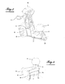
- the figure 4 shows an embodiment of the ball coupling device 1 which does not include a locking lever.
- the coupling head 2 whose general structure is known per se is intended to be mounted on the end of a drawbar of the trailer.
- the coupling head has at its free front end a receiving cavity of the ball 4, of complementary shape to that of the ball.
- the figure 1 shows the coupling head in its position receiving the ball, that is to say the coupling of the coupling head on the towbar.
- the figures 1 and 2 show that the coupling system is provided with a secondary coupling device 15 whose function is to ensure residual guidance of the trailer in case of breakage of one of the components of the coupling between the towing vehicle and the vehicle. trailer.
- This device comprises a flexible wire element 16, such as a chain or a cable, one end of which is fixed to an attachment point 18 of the ball hook 1 while the other end is fixed to an attachment point 19 integral with the coupling head 2.
- the point of attachment 19 is in the form of a tab which is fixed at one end, at 20, to the coupling head 2, on the outer side face thereof, for example by a screw, while the other end comprises fastening means of the link 16, made for example in the form of a hole 21 passage of the link.
- the link for attaching the link to the coupling hook 1, it comprises at the figure 1 a projection 23 provided at the base of the branch 5 carrying the ball 4, wherein is provided a hole 24 for receiving the link 16 or a link for its mechanical connection, if this link is formed by a chain. It is found that the projection 23 extends towards the trailer, in the example shown, at an angle of approximately 45 ° with respect to the longitudinal axis of the branch 5, in front of a rib 25 at the bottom. along the base of the hook. The projection 23 is disposed in the middle of the branch 5 in the width direction thereof.
- the figure 4 shows another embodiment of the attachment projection 23 provided with a mechanical connection hole 24 of the link 16.
- the projection extends substantially vertically under the branch 5 and has the shape of a rib 26 s extending under all the base of the hook between the front branch 5 and the fixing plate 8 directly at the rear of the base 7.
- the particularity and the major advantage of the invention lies in the fact that the attachment projection of the secondary coupling device is provided directly on the ball hitch hook 4 on the free front branch 5 of this hook, below the ball being thus made integrally with the hook.
- the positioning of the attachment projection at a location at the front and under the ball has the particular advantage that, in this position, the link 16 of the secondary coupling device connecting the trailer to the towing vehicle is not put in tension when maneuvering vehicles.
- the attachment point made in one-piece fashion allows an economic gain and eliminates the risks inherent in known devices in which the attachment points are mounted by welding on a transverse beam of the towing vehicle.
- the mounting of the secondary safety fastening device is very simple in the case of the invention, unlike the devices of the state of the art.
- the safety link in the form of a chain or cable, can be dimensioned so that the coupling head, during an accidental disengagement of the head of the ball can not come into contact with the ground shown in the drawings in 26.
- the invention requires only a security link which is located in a central location.
Description
L'invention concerne un système d'attelage notamment pour l'accouplement d'un véhicule de remorque à un véhicule tracteur, du type comprenant un crochet à boule d'attelage monté sur le véhicule tracteur et une tête d'attelage montée sur le véhicule de remorque et destinés à coopérer avec le crochet à boule pour assurer ledit accouplement, et un dispositif d'attelage secondaire comprenant des moyens de lien, tels que des moyens de chaîne, disposé entre des points d'attache situés respectivement du côté du véhicule tracteur et du côté du véhicule de remorque.The invention relates to a coupling system, in particular for coupling a towing vehicle to a towing vehicle, of the type comprising a tow ball hook mounted on the towing vehicle and a coupling head mounted on the vehicle. trailer and intended to cooperate with the ball hook to ensure said coupling, and a secondary coupling device comprising link means, such as chain means, disposed between attachment points located respectively on the side of the tractor vehicle. and on the side of the trailer vehicle.
Les systèmes d'attelage, qui sont connus, comportent des chaînes disposées de part et d'autre du crochet d'attelage et les points de fixation de ces chaînes sont montés, généralement par soudage, sur une poutre transversale prévue sur le véhicule au niveau du pare-chocs arrière. Les points d'attache des chaînes côté remorque sont solidaires de la tête d'attelage de celle-ci. Les systèmes d'attelage connus présentent l'inconvénient majeur que leur dispositif d'attelage secondaire destiné à assurer un guidage résiduel de la remorque en cas de rupture d'un des composants de l'accouplement entre les véhicules tracteur et de remorque a une structure complexe et est difficile à monter.The hitching systems, which are known, comprise chains arranged on either side of the coupling hook and the fixing points of these chains are mounted, generally by welding, on a transverse beam provided on the vehicle at the level of the vehicle. the rear bumper. The attachment points of the trailer side chains are integral with the trailer head thereof. The known coupling systems have the major disadvantage that their secondary coupling device intended to ensure residual guidance of the trailer in the event of breakage of one of the components of the coupling between the tractor and trailer vehicles has a structure complex and is difficult to mount.
Un système d'attelage selon le préambule de la revendication 1 est montré dans document
L'invention a pour but de pallier ces inconvénients.The invention aims to overcome these disadvantages.
Pour atteindre ce but, le système d'attelage selon l'invention est caractérisé en ce que le dispositif d'attelage secondaire comporte un point d'attache côté véhicule tracteur, qui est prévu sur le crochet d'attelage à boule, et en ce que le point d'attache est réalisé de manière monobloc avec le crochet d'attelage.To achieve this purpose, the coupling system according to the invention is characterized in that the secondary coupling device comprises a point of attachment on the towing vehicle, which is provided on the ball hitch hook, and in that that the point of attachment is made in one piece with the coupling hook.
Selon une autre caractéristique de l'invention, le système d'attelage est caractérisé en ce que le point d'attache est réalisé sous forme d'une saillie prévue au niveau de la branche avant porteuse de la boule, en dessous de celle-ci.According to another characteristic of the invention, the coupling system is characterized in that the point of attachment is formed in the form of a projection provided at the level of the front branch carrying the ball, below it. .
Selon encore une autre caractéristique de l'invention, le système d'attelage est caractérisé en ce que la saillie d'attelage s'étend vers l'avant en direction de la tête d'attelage de la remorque.According to yet another characteristic of the invention, the coupling system is characterized in that the hitch projection extends forward towards the hitch head of the trailer.
Selon encore une autre caractéristique de l'invention, le système d'attelage est caractérisé en ce que la saillie d'attache s'étend sensiblement vers le bas.According to yet another characteristic of the invention, the coupling system is characterized in that the attachment projection extends substantially downwards.
Selon encore une autre caractéristique de l'invention, le système d'attelage est caractérisé en ce que la saillie d'attelage comporte un trou de liaison mécanique du lien souple du dispositif d'attelage secondaire.According to yet another characteristic of the invention, the coupling system is characterized in that the coupling projection comprises a mechanical connection hole of the flexible link of the secondary coupling device.
Selon encore une autre caractéristique de l'invention, le système d'attelage est caractérisé en ce que le point d'attache de la tête d'attelage est réalisé sous forme d'une patte fixée sur la tête d'attelage et dont l'extrémité libre est configurée pour la fixation dudit lien.According to yet another characteristic of the invention, the coupling system is characterized in that the point of attachment of the coupling head is in the form of a lug fixed on the coupling head and of which the free end is configured for fixing said link.
Selon encore une autre caractéristique de l'invention, le système d'attelage est caractérisé en ce que la patte d'attache comporte, à son extrémité libre, un trou de liaison mécanique du lien du dispositif d'attelage secondaire.According to yet another characteristic of the invention, the coupling system is characterized in that the fastening tab comprises, at its free end, a mechanical connection hole of the link of the secondary coupling device.
Selon encore une autre caractéristique de l'invention, le système d'attelage est caractérisé en ce que la longueur du lien précité est choisie telle que la tête d'attelage ne vienne pas en contact avec le sol dans le cas d'une défaillance de l'attelage de la tête d'attelage sur la boule du crochet à boule.According to yet another characteristic of the invention, the coupling system is characterized in that the length of the aforementioned link is chosen such that the coupling head does not come into contact with the ground in the event of a failure of the coupling of the coupling head on the ball of the ball hook.
L'invention sera mieux comprise, et d'autres buts, caractéristiques, détails et avantages de celle-ci apparaîtront plus clairement dans la description explicative qui va suivre faite en référence aux dessins schématiques annexés donnés uniquement à titre d'exemple illustrant deux modes de réalisation de l'invention et dans lesquels :
- La
figure 1 est une vue latérale d'un système d'attelage selon l'invention, montrant celui-ci dans sa position d'accouplement de la tête d'attelage d'un véhicule de remorque sur le crochet d'attelage à boule d'un véhicule tracteur ; - la
figure 2 est une vue en perspective du dispositif d'attelage à boule selon l'invention ; - la
figure 3 est une vue latérale du système d'attelage selon lafigure 1 montrant celui-ci dans sa position d'un désaccouplement de la tête d'attelage du crochet d'attelage à boule, le crochet d'attelage et la tête d'attelage n'étant reliés que par le dispositif d'attelage secondaire, et - la
figure 4 est une vue en perspective d'un deuxième mode de réalisation du crochet d'attelage à boule selon l'invention.
- The
figure 1 is a side view of a coupling system according to the invention, showing it in its coupling position of the coupling head of a vehicle trailer on the ball hitch of a towing vehicle; - the
figure 2 is a perspective view of the ball hitch device according to the invention; - the
figure 3 is a side view of the coupling system according to thefigure 1 showing the latter in its position of uncoupling from the coupling head of the ball hitch hook, the coupling hook and the coupling head being connected only by the secondary coupling device, and - the
figure 4 is a perspective view of a second embodiment of the ball hitch hook according to the invention.
Sur les
Les structures du crochet d'attelage 1 et de la tête d'attelage 2 sont de forme conventionnelle. Le crochet d'attelage 1 comporte, comme cela ressort particulièrement clairement de la
La tête d'attelage 2 dont la structure générale est connue en soi est destinée à être montée sur l'extrémité d'un timon de la remorque. La tête d'attelage comporte au niveau de son extrémité avant libre une cavité de réception de la boule 4, de forme complémentaire à celle de cette boule. La
Les
Conformément à l'invention, pour la fixation du lien au crochet d'attelage 1, celui-ci comporte à la
La
Il ressort de la description de l'invention qui vient d'être faite et des figures qui ne sont données, comme celle-ci, qu'à titre d'exemple, que la particularité et l'avantage majeur de l'invention réside dans le fait que la saillie d'attache du dispositif d'attelage secondaire est prévue directement sur le crochet d'attelage à boule 4 sur la branche avant libre 5 de ce crochet, en dessous de la boule en étant ainsi réalisé de manière monobloc avec le crochet. Le positionnement de la saillie d'attache à un emplacement à l'avant et sous la boule présente l'avantage particulier que, dans cette position, le lien 16 du dispositif d'attelage secondaire reliant la remorque au véhicule tracteur n'est pas mis en tension lors des manoeuvres des véhicules. Le point d'attache réalisé de façon monobloc permet un gain économique et supprime les risques inhérents aux dispositifs connus dans lesquels les points d'attache sont montés par soudure sur une poutre transversale du véhicule tracteur. Bien entendu, le montage du dispositif d'attache secondaire de sécurité est très simple dans le cas de l'invention, contrairement aux dispositifs de l'état de la technique. Il est encore à noter que, dans le cas de l'invention, le lien de sécurité, en forme de chaîne ou de câble, peut être dimensionné de façon que la tête d'attelage, lors d'un désengagement accidentel de la tête de la boule ne puisse pas venir en contact du sol indiqué sur les dessins en 26. De plus, l'invention ne nécessite qu'un lien de sécurité qui est situé dans un emplacement central.It follows from the description of the invention that has just been made and figures which are given, as this one, only by way of example, that the particularity and the major advantage of the invention lies in the fact that the attachment projection of the secondary coupling device is provided directly on the
Claims (8)
- A coupling system notably for coupling a trailer vehicle to a tractor vehicle, of the type comprising a hook-shaped device with a coupling ball mounted on the tractor vehicle and a coupling head mounted on the trailer vehicle and intended to cooperate with the ball of the hook-shaped device so as to thereby ensure said coupling, and a secondary safety coupling device comprising linking means, such as chain or cable means, positioned between attachment points located on the side of the tractor vehicle and of the trailer vehicle respectively, and the secondary safety coupling device (15) including an attachment point (18) on the side of the tractor vehicle, which is provided on the ball hook (1); characterized in that the attachment point (15) is made in one piece with the coupling hook (1).
- The coupling system according to claim 1, characterized in that the attachment point is made as a protrusion (23) provided at the front branch (5) bearing the ball (4), below the latter.
- The coupling system according to claim 2, characterized in that the coupling protrusion (23) extends forwards towards the coupling head (2) of the trailer.
- The coupling system according to one of claims 1 or 2, characterized in that the attachment protrusion (26) substantially extends downwards.
- The coupling system according to one of claims 2 to 4, characterized in that the coupling protrusion includes a mechanical link hole (24) of the flexible connection of the secondary coupling device.
- The coupling system according to one of claims 1 to 5, characterized in that the attachment point (19) of the coupling head (1) is made as a tab attached on the coupling head (1) and the free end of which is configured for attachment of said connection.
- The coupling system according to claim 6, characterized in that the attachment tab (19) at its free end includes a mechanical link hole (21) for the connection (16) of the secondary coupling device.
- The coupling system according to one of claims 1 to 7, characterized in that the length of the aforementioned connection (16) is selected so that the coupling head (2) does not come into contact with the ground in the case of a failure of the coupling of the coupling head (1) on the ball (4) of the ball hook (1).
Applications Claiming Priority (1)
| Application Number | Priority Date | Filing Date | Title |
|---|---|---|---|
| FR1051313A FR2956617B1 (en) | 2010-02-24 | 2010-02-24 | COUPLING SYSTEM, IN PARTICULAR FOR COUPLING A TRAILER VEHICLE TO A TRACTOR VEHICLE |
Publications (2)
| Publication Number | Publication Date |
|---|---|
| EP2360035A1 EP2360035A1 (en) | 2011-08-24 |
| EP2360035B1 true EP2360035B1 (en) | 2015-05-13 |
Family
ID=42737948
Family Applications (1)
| Application Number | Title | Priority Date | Filing Date |
|---|---|---|---|
| EP20110155800 Revoked EP2360035B1 (en) | 2010-02-24 | 2011-02-24 | Coupling system in particular for coupling a trailer vehicle to a tractor vehicle |
Country Status (2)
| Country | Link |
|---|---|
| EP (1) | EP2360035B1 (en) |
| FR (1) | FR2956617B1 (en) |
Families Citing this family (1)
| Publication number | Priority date | Publication date | Assignee | Title |
|---|---|---|---|---|
| FR2993824B1 (en) | 2012-07-26 | 2015-07-24 | Raphael Colombie | DEVICE FOR ATTACHING A TRAILER TO A TRACTOR VEHICLE |
Citations (15)
| Publication number | Priority date | Publication date | Assignee | Title |
|---|---|---|---|---|
| US2788990A (en) | 1954-12-21 | 1957-04-16 | Barcafer John | Ball and socket hitch with safety chain |
| US2998982A (en) | 1960-05-31 | 1961-09-05 | Clarence A Brazil | Trailer hitch safety device |
| US3549173A (en) | 1969-01-29 | 1970-12-22 | Harry M Stanfield | Safety trailer device |
| NL7216903A (en) | 1972-12-13 | 1974-06-17 | ||
| US3870343A (en) | 1974-05-02 | 1975-03-11 | Loop A Line Inc | Trailer hitch and safety connector |
| DE8315240U1 (en) | 1983-05-24 | 1983-09-29 | Peka-Fahrzeugbau Gmbh + Co Kg, 7500 Karlsruhe | Socket holder |
| US4467598A (en) | 1981-04-28 | 1984-08-28 | Wells William M | Energy absorbing trailer chain |
| DE3904682A1 (en) | 1989-02-16 | 1990-08-23 | Bayerische Motoren Werke Ag | Trailer coupling for a motor vehicle |
| US5072964A (en) | 1989-12-13 | 1991-12-17 | Schule Earl A | Trailer coupler safety cable device |
| US5362084A (en) | 1993-03-08 | 1994-11-08 | Edwards Jerry A | Cable carrier for vehicle hitch |
| US5566965A (en) | 1995-08-21 | 1996-10-22 | Applegate; John M. | Trailer safety chain adaptor |
| DE29906947U1 (en) | 1999-04-19 | 1999-07-08 | Bytomski | Ball coupling |
| WO2001081106A1 (en) | 2000-04-20 | 2001-11-01 | Tow Hook Concepts, Llc | Apparatus for maintaining connection between a towing vehicle and a trailer |
| US6644679B1 (en) | 2002-01-28 | 2003-11-11 | Brad A. Warren | Towing attachment and method |
| US20060186639A1 (en) | 2005-02-18 | 2006-08-24 | Israel Rosario | Towing accessory system |
-
2010
- 2010-02-24 FR FR1051313A patent/FR2956617B1/en active Active
-
2011
- 2011-02-24 EP EP20110155800 patent/EP2360035B1/en not_active Revoked
Patent Citations (15)
| Publication number | Priority date | Publication date | Assignee | Title |
|---|---|---|---|---|
| US2788990A (en) | 1954-12-21 | 1957-04-16 | Barcafer John | Ball and socket hitch with safety chain |
| US2998982A (en) | 1960-05-31 | 1961-09-05 | Clarence A Brazil | Trailer hitch safety device |
| US3549173A (en) | 1969-01-29 | 1970-12-22 | Harry M Stanfield | Safety trailer device |
| NL7216903A (en) | 1972-12-13 | 1974-06-17 | ||
| US3870343A (en) | 1974-05-02 | 1975-03-11 | Loop A Line Inc | Trailer hitch and safety connector |
| US4467598A (en) | 1981-04-28 | 1984-08-28 | Wells William M | Energy absorbing trailer chain |
| DE8315240U1 (en) | 1983-05-24 | 1983-09-29 | Peka-Fahrzeugbau Gmbh + Co Kg, 7500 Karlsruhe | Socket holder |
| DE3904682A1 (en) | 1989-02-16 | 1990-08-23 | Bayerische Motoren Werke Ag | Trailer coupling for a motor vehicle |
| US5072964A (en) | 1989-12-13 | 1991-12-17 | Schule Earl A | Trailer coupler safety cable device |
| US5362084A (en) | 1993-03-08 | 1994-11-08 | Edwards Jerry A | Cable carrier for vehicle hitch |
| US5566965A (en) | 1995-08-21 | 1996-10-22 | Applegate; John M. | Trailer safety chain adaptor |
| DE29906947U1 (en) | 1999-04-19 | 1999-07-08 | Bytomski | Ball coupling |
| WO2001081106A1 (en) | 2000-04-20 | 2001-11-01 | Tow Hook Concepts, Llc | Apparatus for maintaining connection between a towing vehicle and a trailer |
| US6644679B1 (en) | 2002-01-28 | 2003-11-11 | Brad A. Warren | Towing attachment and method |
| US20060186639A1 (en) | 2005-02-18 | 2006-08-24 | Israel Rosario | Towing accessory system |
Non-Patent Citations (3)
| Title |
|---|
| "Anhängefahrzeuge", BERICHT ÜBER DIE 80. SITZUNG DES AA-I 4, 20 October 2008 (2008-10-20), pages 1 - 4, XP055261099 |
| ADAM OPEL, BETRIEBSANLEITUNG OPEL INSIGNIA ARTIKELNUMMER 09 921063, August 2009 (2009-08-01), XP055261098 |
| ISO: "Road vehicles- Towing devices- Safety devices", ENTWURF NORMUNG DER ABSCHLEPPÖSE V1.0, 28 August 2008 (2008-08-28), XP055261101 |
Also Published As
| Publication number | Publication date |
|---|---|
| FR2956617B1 (en) | 2012-07-20 |
| FR2956617A1 (en) | 2011-08-26 |
| EP2360035A1 (en) | 2011-08-24 |
Similar Documents
| Publication | Publication Date | Title |
|---|---|---|
| US20030015856A1 (en) | Tow hitch assembly for all-terrain vehicles | |
| US9180846B2 (en) | Trailer tongue connection unit | |
| US20110210530A1 (en) | Tow hitch | |
| EP0288366A1 (en) | Device for attaching a towing hitch to a motor vehicle | |
| EP2360035B1 (en) | Coupling system in particular for coupling a trailer vehicle to a tractor vehicle | |
| EP1051894B1 (en) | Tractor tow bar adaptor | |
| FR2651470A1 (en) | CYCLE HOLDER FOR EQUIPPING A VEHICLE. | |
| EP0020703A1 (en) | Fastening device for trailer and trailer comprising such device. | |
| EP2533991B1 (en) | Motor vehicle hitch device and vehicle equipped with such a hitch device | |
| FR2570991A1 (en) | Attachment device for towing any road vehicle | |
| KR100835599B1 (en) | An separable traction apparatus | |
| FR2463688A1 (en) | TOW HITCH FOR TRAILER | |
| US7207586B2 (en) | Trailer hitch assembly for a bicycle | |
| FR2876957A1 (en) | Drawbar for industrial truck, has guiding plate to guide free end of towing hook, by traction force exerted by industrial tow tractor, between cross-member and front stopper that immobilizes hook in hitching standby position | |
| EP3119620B1 (en) | System for coupling a range of carriers with a swivel hook fixed to the rear structure of a motor vehicle | |
| EP3840974B1 (en) | Module configured to be assembled in a passenger compartment of a motor vehicle | |
| CH653628A5 (en) | Assistance device for manoeuvring a vehicle of the semi-trailer type | |
| FR2609668A1 (en) | Trailer hitching jib | |
| EP0256951B1 (en) | Connecting device for reversible swinging bars in a pick-up drawbar hitch | |
| FR3138796A1 (en) | Load carrier of a motor vehicle | |
| FR3106796A1 (en) | Motor vehicle wiper adapter | |
| EP0322328A1 (en) | Forward-elongating device for a flat bed container carrying semi-trailers | |
| FR2566713A1 (en) | HITCHING DEVICE, IN PARTICULAR FOR TOURISM CARS | |
| CA2481361A1 (en) | Automatic hitch system | |
| EP2093130A1 (en) | Assembly of a cradle, lashing rope and a hitch tongue of a vehicle and vehicle equipped with such an assembly |
Legal Events
| Date | Code | Title | Description |
|---|---|---|---|
| PUAI | Public reference made under article 153(3) epc to a published international application that has entered the european phase |
Free format text: ORIGINAL CODE: 0009012 |
|
| AK | Designated contracting states |
Kind code of ref document: A1 Designated state(s): AL AT BE BG CH CY CZ DE DK EE ES FI FR GB GR HR HU IE IS IT LI LT LU LV MC MK MT NL NO PL PT RO RS SE SI SK SM TR |
|
| AX | Request for extension of the european patent |
Extension state: BA ME |
|
| 17P | Request for examination filed |
Effective date: 20120106 |
|
| GRAP | Despatch of communication of intention to grant a patent |
Free format text: ORIGINAL CODE: EPIDOSNIGR1 |
|
| INTG | Intention to grant announced |
Effective date: 20140827 |
|
| GRAS | Grant fee paid |
Free format text: ORIGINAL CODE: EPIDOSNIGR3 |
|
| GRAA | (expected) grant |
Free format text: ORIGINAL CODE: 0009210 |
|
| AK | Designated contracting states |
Kind code of ref document: B1 Designated state(s): AL AT BE BG CH CY CZ DE DK EE ES FI FR GB GR HR HU IE IS IT LI LT LU LV MC MK MT NL NO PL PT RO RS SE SI SK SM TR |
|
| REG | Reference to a national code |
Ref country code: GB Ref legal event code: FG4D Free format text: NOT ENGLISH |
|
| REG | Reference to a national code |
Ref country code: CH Ref legal event code: EP |
|
| REG | Reference to a national code |
Ref country code: IE Ref legal event code: FG4D Free format text: LANGUAGE OF EP DOCUMENT: FRENCH |
|
| REG | Reference to a national code |
Ref country code: AT Ref legal event code: REF Ref document number: 726687 Country of ref document: AT Kind code of ref document: T Effective date: 20150615 |
|
| REG | Reference to a national code |
Ref country code: DE Ref legal event code: R096 Ref document number: 602011016403 Country of ref document: DE Effective date: 20150625 |
|
| REG | Reference to a national code |
Ref country code: AT Ref legal event code: MK05 Ref document number: 726687 Country of ref document: AT Kind code of ref document: T Effective date: 20150513 |
|
| REG | Reference to a national code |
Ref country code: NL Ref legal event code: MP Effective date: 20150513 |
|
| REG | Reference to a national code |
Ref country code: LT Ref legal event code: MG4D |
|
| PG25 | Lapsed in a contracting state [announced via postgrant information from national office to epo] |
Ref country code: NO Free format text: LAPSE BECAUSE OF FAILURE TO SUBMIT A TRANSLATION OF THE DESCRIPTION OR TO PAY THE FEE WITHIN THE PRESCRIBED TIME-LIMIT Effective date: 20150813 Ref country code: ES Free format text: LAPSE BECAUSE OF FAILURE TO SUBMIT A TRANSLATION OF THE DESCRIPTION OR TO PAY THE FEE WITHIN THE PRESCRIBED TIME-LIMIT Effective date: 20150513 Ref country code: FI Free format text: LAPSE BECAUSE OF FAILURE TO SUBMIT A TRANSLATION OF THE DESCRIPTION OR TO PAY THE FEE WITHIN THE PRESCRIBED TIME-LIMIT Effective date: 20150513 Ref country code: PT Free format text: LAPSE BECAUSE OF FAILURE TO SUBMIT A TRANSLATION OF THE DESCRIPTION OR TO PAY THE FEE WITHIN THE PRESCRIBED TIME-LIMIT Effective date: 20150914 Ref country code: HR Free format text: LAPSE BECAUSE OF FAILURE TO SUBMIT A TRANSLATION OF THE DESCRIPTION OR TO PAY THE FEE WITHIN THE PRESCRIBED TIME-LIMIT Effective date: 20150513 Ref country code: LT Free format text: LAPSE BECAUSE OF FAILURE TO SUBMIT A TRANSLATION OF THE DESCRIPTION OR TO PAY THE FEE WITHIN THE PRESCRIBED TIME-LIMIT Effective date: 20150513 |
|
| PG25 | Lapsed in a contracting state [announced via postgrant information from national office to epo] |
Ref country code: BG Free format text: LAPSE BECAUSE OF FAILURE TO SUBMIT A TRANSLATION OF THE DESCRIPTION OR TO PAY THE FEE WITHIN THE PRESCRIBED TIME-LIMIT Effective date: 20150813 Ref country code: AT Free format text: LAPSE BECAUSE OF FAILURE TO SUBMIT A TRANSLATION OF THE DESCRIPTION OR TO PAY THE FEE WITHIN THE PRESCRIBED TIME-LIMIT Effective date: 20150513 Ref country code: GR Free format text: LAPSE BECAUSE OF FAILURE TO SUBMIT A TRANSLATION OF THE DESCRIPTION OR TO PAY THE FEE WITHIN THE PRESCRIBED TIME-LIMIT Effective date: 20150814 Ref country code: RS Free format text: LAPSE BECAUSE OF FAILURE TO SUBMIT A TRANSLATION OF THE DESCRIPTION OR TO PAY THE FEE WITHIN THE PRESCRIBED TIME-LIMIT Effective date: 20150513 Ref country code: IS Free format text: LAPSE BECAUSE OF FAILURE TO SUBMIT A TRANSLATION OF THE DESCRIPTION OR TO PAY THE FEE WITHIN THE PRESCRIBED TIME-LIMIT Effective date: 20150913 Ref country code: LV Free format text: LAPSE BECAUSE OF FAILURE TO SUBMIT A TRANSLATION OF THE DESCRIPTION OR TO PAY THE FEE WITHIN THE PRESCRIBED TIME-LIMIT Effective date: 20150513 |
|
| PG25 | Lapsed in a contracting state [announced via postgrant information from national office to epo] |
Ref country code: DK Free format text: LAPSE BECAUSE OF FAILURE TO SUBMIT A TRANSLATION OF THE DESCRIPTION OR TO PAY THE FEE WITHIN THE PRESCRIBED TIME-LIMIT Effective date: 20150513 Ref country code: EE Free format text: LAPSE BECAUSE OF FAILURE TO SUBMIT A TRANSLATION OF THE DESCRIPTION OR TO PAY THE FEE WITHIN THE PRESCRIBED TIME-LIMIT Effective date: 20150513 |
|
| REG | Reference to a national code |
Ref country code: DE Ref legal event code: R026 Ref document number: 602011016403 Country of ref document: DE |
|
| PLBI | Opposition filed |
Free format text: ORIGINAL CODE: 0009260 |
|
| PLBI | Opposition filed |
Free format text: ORIGINAL CODE: 0009260 |
|
| REG | Reference to a national code |
Ref country code: FR Ref legal event code: PLFP Year of fee payment: 6 |
|
| PG25 | Lapsed in a contracting state [announced via postgrant information from national office to epo] |
Ref country code: RO Free format text: LAPSE BECAUSE OF NON-PAYMENT OF DUE FEES Effective date: 20150513 Ref country code: CZ Free format text: LAPSE BECAUSE OF FAILURE TO SUBMIT A TRANSLATION OF THE DESCRIPTION OR TO PAY THE FEE WITHIN THE PRESCRIBED TIME-LIMIT Effective date: 20150513 Ref country code: SK Free format text: LAPSE BECAUSE OF FAILURE TO SUBMIT A TRANSLATION OF THE DESCRIPTION OR TO PAY THE FEE WITHIN THE PRESCRIBED TIME-LIMIT Effective date: 20150513 Ref country code: PL Free format text: LAPSE BECAUSE OF FAILURE TO SUBMIT A TRANSLATION OF THE DESCRIPTION OR TO PAY THE FEE WITHIN THE PRESCRIBED TIME-LIMIT Effective date: 20150513 |
|
| 26 | Opposition filed |
Opponent name: WESTFALIA - AUTOMOTIVE GMBH Effective date: 20160129 |
|
| 26 | Opposition filed |
Opponent name: SCAMBIA HOLDINGS CYPRUS LIMITED Effective date: 20160210 |
|
| PLAX | Notice of opposition and request to file observation + time limit sent |
Free format text: ORIGINAL CODE: EPIDOSNOBS2 |
|
| PG25 | Lapsed in a contracting state [announced via postgrant information from national office to epo] |
Ref country code: SI Free format text: LAPSE BECAUSE OF FAILURE TO SUBMIT A TRANSLATION OF THE DESCRIPTION OR TO PAY THE FEE WITHIN THE PRESCRIBED TIME-LIMIT Effective date: 20150513 |
|
| PLAF | Information modified related to communication of a notice of opposition and request to file observations + time limit |
Free format text: ORIGINAL CODE: EPIDOSCOBS2 |
|
| PLBB | Reply of patent proprietor to notice(s) of opposition received |
Free format text: ORIGINAL CODE: EPIDOSNOBS3 |
|
| PG25 | Lapsed in a contracting state [announced via postgrant information from national office to epo] |
Ref country code: LU Free format text: LAPSE BECAUSE OF FAILURE TO SUBMIT A TRANSLATION OF THE DESCRIPTION OR TO PAY THE FEE WITHIN THE PRESCRIBED TIME-LIMIT Effective date: 20160224 Ref country code: MC Free format text: LAPSE BECAUSE OF FAILURE TO SUBMIT A TRANSLATION OF THE DESCRIPTION OR TO PAY THE FEE WITHIN THE PRESCRIBED TIME-LIMIT Effective date: 20150513 |
|
| REG | Reference to a national code |
Ref country code: CH Ref legal event code: PL |
|
| GBPC | Gb: european patent ceased through non-payment of renewal fee |
Effective date: 20160224 |
|
| PG25 | Lapsed in a contracting state [announced via postgrant information from national office to epo] |
Ref country code: CH Free format text: LAPSE BECAUSE OF NON-PAYMENT OF DUE FEES Effective date: 20160229 Ref country code: LI Free format text: LAPSE BECAUSE OF NON-PAYMENT OF DUE FEES Effective date: 20160229 |
|
| REG | Reference to a national code |
Ref country code: IE Ref legal event code: MM4A |
|
| PG25 | Lapsed in a contracting state [announced via postgrant information from national office to epo] |
Ref country code: GB Free format text: LAPSE BECAUSE OF NON-PAYMENT OF DUE FEES Effective date: 20160224 Ref country code: IE Free format text: LAPSE BECAUSE OF NON-PAYMENT OF DUE FEES Effective date: 20160224 |
|
| REG | Reference to a national code |
Ref country code: FR Ref legal event code: PLFP Year of fee payment: 7 |
|
| RDAF | Communication despatched that patent is revoked |
Free format text: ORIGINAL CODE: EPIDOSNREV1 |
|
| STAA | Information on the status of an ep patent application or granted ep patent |
Free format text: STATUS: THE PATENT HAS BEEN GRANTED |
|
| PGFP | Annual fee paid to national office [announced via postgrant information from national office to epo] |
Ref country code: FR Payment date: 20170220 Year of fee payment: 7 |
|
| REG | Reference to a national code |
Ref country code: DE Ref legal event code: R064 Ref document number: 602011016403 Country of ref document: DE Ref country code: DE Ref legal event code: R103 Ref document number: 602011016403 Country of ref document: DE |
|
| PGFP | Annual fee paid to national office [announced via postgrant information from national office to epo] |
Ref country code: BE Payment date: 20170224 Year of fee payment: 7 |
|
| PG25 | Lapsed in a contracting state [announced via postgrant information from national office to epo] |
Ref country code: SE Free format text: LAPSE BECAUSE OF FAILURE TO SUBMIT A TRANSLATION OF THE DESCRIPTION OR TO PAY THE FEE WITHIN THE PRESCRIBED TIME-LIMIT Effective date: 20150513 Ref country code: NL Free format text: LAPSE BECAUSE OF FAILURE TO SUBMIT A TRANSLATION OF THE DESCRIPTION OR TO PAY THE FEE WITHIN THE PRESCRIBED TIME-LIMIT Effective date: 20150513 |
|
| PGFP | Annual fee paid to national office [announced via postgrant information from national office to epo] |
Ref country code: IT Payment date: 20170221 Year of fee payment: 7 |
|
| PGFP | Annual fee paid to national office [announced via postgrant information from national office to epo] |
Ref country code: DE Payment date: 20170428 Year of fee payment: 7 |
|
| RDAG | Patent revoked |
Free format text: ORIGINAL CODE: 0009271 |
|
| STAA | Information on the status of an ep patent application or granted ep patent |
Free format text: STATUS: PATENT REVOKED |
|
| PG25 | Lapsed in a contracting state [announced via postgrant information from national office to epo] |
Ref country code: MT Free format text: LAPSE BECAUSE OF FAILURE TO SUBMIT A TRANSLATION OF THE DESCRIPTION OR TO PAY THE FEE WITHIN THE PRESCRIBED TIME-LIMIT Effective date: 20150513 |
|
| 27W | Patent revoked |
Effective date: 20170508 |
|
| PG25 | Lapsed in a contracting state [announced via postgrant information from national office to epo] |
Ref country code: AL Free format text: LAPSE BECAUSE OF FAILURE TO SUBMIT A TRANSLATION OF THE DESCRIPTION OR TO PAY THE FEE WITHIN THE PRESCRIBED TIME-LIMIT Effective date: 20150513 |
|
| STAA | Information on the status of an ep patent application or granted ep patent |
Free format text: STATUS: PATENT REVOKED |
|
| PG25 | Lapsed in a contracting state [announced via postgrant information from national office to epo] |
Ref country code: CY Free format text: LAPSE BECAUSE OF FAILURE TO SUBMIT A TRANSLATION OF THE DESCRIPTION OR TO PAY THE FEE WITHIN THE PRESCRIBED TIME-LIMIT Effective date: 20150513 |
|
| PG25 | Lapsed in a contracting state [announced via postgrant information from national office to epo] |
Ref country code: TR Free format text: LAPSE BECAUSE OF FAILURE TO SUBMIT A TRANSLATION OF THE DESCRIPTION OR TO PAY THE FEE WITHIN THE PRESCRIBED TIME-LIMIT Effective date: 20150513 |