EP2357504A2 - Vorrichtung zum Laserschutz mit einem kraftentkoppelten Laserschutzgehäuse - Google Patents
Vorrichtung zum Laserschutz mit einem kraftentkoppelten Laserschutzgehäuse Download PDFInfo
- Publication number
- EP2357504A2 EP2357504A2 EP11151787A EP11151787A EP2357504A2 EP 2357504 A2 EP2357504 A2 EP 2357504A2 EP 11151787 A EP11151787 A EP 11151787A EP 11151787 A EP11151787 A EP 11151787A EP 2357504 A2 EP2357504 A2 EP 2357504A2
- Authority
- EP
- European Patent Office
- Prior art keywords
- laser
- laser protective
- socket
- protective housing
- carrier body
- Prior art date
- Legal status (The legal status is an assumption and is not a legal conclusion. Google has not performed a legal analysis and makes no representation as to the accuracy of the status listed.)
- Granted
Links
- 230000001681 protective effect Effects 0.000 claims abstract description 49
- 230000003287 optical effect Effects 0.000 claims abstract description 37
- 239000004033 plastic Substances 0.000 claims abstract description 5
- 239000000463 material Substances 0.000 claims abstract description 4
- NJPPVKZQTLUDBO-UHFFFAOYSA-N novaluron Chemical compound C1=C(Cl)C(OC(F)(F)C(OC(F)(F)F)F)=CC=C1NC(=O)NC(=O)C1=C(F)C=CC=C1F NJPPVKZQTLUDBO-UHFFFAOYSA-N 0.000 claims 2
- 230000000694 effects Effects 0.000 description 2
- 230000005855 radiation Effects 0.000 description 2
- 230000009471 action Effects 0.000 description 1
- 229910052782 aluminium Inorganic materials 0.000 description 1
- XAGFODPZIPBFFR-UHFFFAOYSA-N aluminium Chemical compound [Al] XAGFODPZIPBFFR-UHFFFAOYSA-N 0.000 description 1
- 230000008859 change Effects 0.000 description 1
- 238000010276 construction Methods 0.000 description 1
- 230000008878 coupling Effects 0.000 description 1
- 238000010168 coupling process Methods 0.000 description 1
- 238000005859 coupling reaction Methods 0.000 description 1
- 239000013013 elastic material Substances 0.000 description 1
- 230000006870 function Effects 0.000 description 1
- 230000036541 health Effects 0.000 description 1
- 231100000206 health hazard Toxicity 0.000 description 1
- 238000001746 injection moulding Methods 0.000 description 1
- 238000009434 installation Methods 0.000 description 1
- 229910052751 metal Inorganic materials 0.000 description 1
- 239000002184 metal Substances 0.000 description 1
- 230000009993 protective function Effects 0.000 description 1
- 230000002277 temperature effect Effects 0.000 description 1
Images
Classifications
-
- G—PHYSICS
- G02—OPTICS
- G02B—OPTICAL ELEMENTS, SYSTEMS OR APPARATUS
- G02B7/00—Mountings, adjusting means, or light-tight connections, for optical elements
- G02B7/18—Mountings, adjusting means, or light-tight connections, for optical elements for prisms; for mirrors
- G02B7/182—Mountings, adjusting means, or light-tight connections, for optical elements for prisms; for mirrors for mirrors
- G02B7/1822—Mountings, adjusting means, or light-tight connections, for optical elements for prisms; for mirrors for mirrors comprising means for aligning the optical axis
- G02B7/1824—Manual alignment
- G02B7/1825—Manual alignment made by screws, e.g. for laser mirrors
-
- B—PERFORMING OPERATIONS; TRANSPORTING
- B23—MACHINE TOOLS; METAL-WORKING NOT OTHERWISE PROVIDED FOR
- B23K—SOLDERING OR UNSOLDERING; WELDING; CLADDING OR PLATING BY SOLDERING OR WELDING; CUTTING BY APPLYING HEAT LOCALLY, e.g. FLAME CUTTING; WORKING BY LASER BEAM
- B23K26/00—Working by laser beam, e.g. welding, cutting or boring
- B23K26/70—Auxiliary operations or equipment
- B23K26/702—Auxiliary equipment
- B23K26/706—Protective screens
Definitions
- the invention relates to a device for laser protection.
- the device comprises a holder holding an optical element and a socket holding the holder.
- an associated laser protection housing is formed substantially light-tight and coupled to the base.
- Lasers are used in a wide variety of technical fields.
- the laser beams generated by the lasers are deflected by the laser to external units, collimated, focused and / or fanned out.
- deflecting a laser beam it is known to direct the laser beam onto a deflection mirror.
- collimating, focusing or fanning it is known to influence the laser beam by means of one or more lenses.
- An orientation of the optical element used determines the beam path and / or the beam shape of the deflected or influenced laser beam.
- the laser beams deflecting or influencing components in particular the deflection mirror or the lens, often have to be very precise be adjusted. Even slightest influences on the optical element, for example due to external force or temperature changes, can lead to a misalignment of the optical element and to a change in the laser beam path or the laser beam shape. In a protected with the laser protective housing optical element, a force on the laser protective housing can lead to a misalignment of the optical element. Therefore, it is known to arrange the laser protection housing without contact to the protected by the laser protective housing optical element. Due to the freedom from contact, however, gaps may arise between the components carrying the optical element and the laser protective housing. The laser radiation can penetrate through these gaps and thus become a health hazard. In addition, it is complicated to precisely adjust the protected by the laser protective housing optical element and / or to mount on an optical table.
- the object of the invention is to provide an apparatus for laser protection, which contributes to a protection of the optical element from external influences and to a protection of the environment from the laser radiation deflected and / or influenced by means of the optical element.
- the invention is characterized in that the laser protection housing is coupled via a flexible element with the base, that the laser protection housing is tiltable relative to the base.
- the coupling of the laser protection housing to the socket via the flexible element allows the laser protection housing to be light-tight with the socket connect and yet an external effect, which acts on the laser protective housing, not undamped on the base and thus, for example, on the mirror mount that holds the deflecting mirror to transfer.
- the external action may be, for example, a mechanical force or a thermal effect of temperature.
- the optical element comprises, for example, a deflection mirror and / or one or more lenses.
- the laser protection housing is formed substantially light-tight, which means that the laser protection housing is made light-tight except for openings for mounting the base, the optical element or the beam guide to the optical element.
- the laser protection housing comprises a carrier body and a laser protection cover held by the carrier body, wherein the carrier body, the flexible element and the base are integrally formed. This can contribute to the fact that the laser contactor housing can be produced in a particularly simple manner.
- the flexibility of the flexible element is given for example due to the geometry of the flexible element.
- the flexible element is wave-shaped and / or sheet-like in cross-section.
- the flexibility of the flexible element is given due to the material of the flexible element.
- the flexible element comprises plastic and / or rubber.
- a vertical position of the laser protection cover with respect to the base by a thumbwheel is predetermined and / or the laser protective housing comprises a removable lid.
- the cover allows access from above into the laser protection housing and thus an adjustment of the holder, which is preferably coupled in the vertical direction movable with the base.
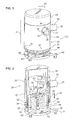
- FIG. 1 shows a device 20 with a laser protective housing 22.
- the laser protective housing 22 has a cover 24, a laser protective cover 25 and a carrier body 36.
- the laser protection cover 25 has a first recess 27 with a first connection 26 for receiving a first laser protection tube, not shown, and a second recess 29 with a second connection 28 for receiving a second laser protection tube, not shown. Otherwise, the laser protection housing 22 is formed light-tight.
- the laser protection tubes can be fixed by means of first locking screws 30 at the two terminals 26, 28. With the aid of the laser protection tubes, a laser beam from a laser light source to the device 20 and from the device 20 towards a with respect to the laser light source and the device 20 external unit, such as a microscope, are steered.
- the laser protection cover 25 is fixed by means of second locking screws 32 on a thumbwheel 34.
- the thumbwheel 34 is coupled via an internal thread of the thumbwheel 34 and an external thread of the carrier body 36 with the carrier body 36.
- the carrier body 36 is coupled via a bottom plate 38 with a first screw clamp 40 and a second screw clamp 42.
- only one or more screw terminals can be arranged.
- the two screw terminals 40, 42 allow fixing of the device 20 to an optical table, not shown.
- magnets (not shown) may be arranged in the bottom plate 38, which magnets may be coupled to corresponding magnets in the optical table. The magnets allow for easy alignment of the device 20 on the optical stage and facilitate the positioning of the device 20 on the optical table.
- the laser protective housing 22 is tilted due to an external force against a vertical 44 in a tilting direction 46.
- FIG. 2 shows a perspective sectional view through the device 20 according to FIG. 1 from the fact that the tilting of the laser protective housing 22 is possible due to a flexible member 48 which connects the carrier body 36 of the laser protective housing 22 with a base 50.
- the base 50 has a vertical recess 54 in which at least partially a support column 52 of a holder is arranged.
- a collar 53 allows the vertical adjustment of the support column 52 along a vertical direction of movement 55 in the vertical recess 54.
- a locking pin 56 helps to define the support column 52 in the vertical direction.
- the holder holds an optical element.
- the Holder is a mirror holder 58 and the optical element is a deflection mirror 60.
- the holder may be a lens holder holding one or more lenses, not shown.
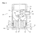
- FIG. 3 shows a side view of the sectional view according to FIG. 2 , in addition to the in FIG. 2 shown a third screw 65 for fixing the device 20 is shown on the optical table.
- the laser protective housing 22 protects the optical element formed as deflecting mirror 60 for this example against an external force and / or temperature effect. At the same time, the laser protection housing 22 protects the surroundings of the device 20 from laser beams which are deflected by means of the deflection mirror 60. In addition, the laser protection housing 22 protects the deflection mirror 60 against access and misalignment.
- the lid 24 allows access to the mirror holder 58 and thus an adjustment of the deflection mirror 60 even after mounting the laser protection housing 22, in particular the laser protection cover 25, for example, a fine adjustment of the mirror holder 58 after placing the laser protection cover 25 and before placing the lid 24 done.
- the flexible element 48 shown in the figures is given its flexibility by the sheet-like, ie particularly thin, design of the material used for the flexible element 48.
- the flexible element 48 is formed so thin that a tilting of the laser protective housing 22 is possible without a relevant transfer of force on the base 50 and thus on the mirror mount 58 and the deflection mirror 60 takes place.
- the flexibility of the flexible element 48 may be given by a wave-shaped profile of the flexible element 48.
- the base 50, the flexible element 48 and the carrier body 36 of the laser protective housing 22 are integrally formed.
- the base 50, the flexible member 48 and the carrier body 36 form part of the laser protection housing 22.
- the base 50, the flexible member 48 and the carrier body 36 are milled from a one-piece aluminum or plastic body.
- the base 50 and the bottom plate 38 are integrally formed.
- the base 50, the carrier body 36 and the flexible element 48 may also be formed in several pieces, be manufactured in an injection molding process and / or of metal.
- the laser protective housing 22 can be mounted independently of the mirror mount 58 in the multi-piece configuration of the carrier body 36, the flexible member 48 and the base 50.
- the flexible element 48 may comprise in whole or in part an elastic material, in particular rubber.
- the mirror holder 58 allows an adjustment of the deflection mirror 60.
- the deflection mirror 60 is adapted to a beam height and a beam deflection to be deflected of the laser beam to be deflected.
- the adjusting wheel 34 allows a vertical adjustment of the laser protection cover 25 even after adjustment of the deflection mirror 60 and the cover 24.
- a rotation of the adjusting wheel 34 leads to a movement of the laser protective cover 25 and thus the terminals 26, 28 along the direction of movement 43.
- the laser protection cover 22 can thus be adapted to the vertical position of the deflection mirror 60 and / or to a vertical position of the laser protective tubes to be connected.
- the screw terminals 40, 42, 65 preferably engage in holes, not shown, of the optical table or an optical bench, not shown.
- the laser protection cover 25 may be formed such that it defines the adjusting ring 53 in addition to the described protective functions and thus additionally or alternatively to the Festestellky 56 determines the vertical position of the support column 52 and thus the entire mirror mount 58.
- the optical element may consist of a mirror-lens combination.
Landscapes
- Physics & Mathematics (AREA)
- Engineering & Computer Science (AREA)
- Optics & Photonics (AREA)
- Plasma & Fusion (AREA)
- Mechanical Engineering (AREA)
- General Physics & Mathematics (AREA)
- Lasers (AREA)
Abstract
Description
- Die Erfindung betrifft eine Vorrichtung zum Laserschutz. Die Vorrichtung umfasst eine Halterung die ein optisches Element hält, und einen Sockel, der die Halterung hält. ein zugehöriges Laserschutzgehäuse ist im Wesentlichen lichtdicht ausgebildet und mit dem Sockel gekoppelt.
- Laser finden in den unterschiedlichsten Bereichen der Technik ihre Anwendung. Die von den Lasern erzeugten Laserstrahlen werden beispielsweise vom Laser zu externen Baueinheiten umgelenkt, kollimiert, fokussiert und/oder aufgefächert. Zum Umlenken eines Laserstrahls ist es bekannt, den Laserstrahl auf einen Umlenkspiegel zu richten. Zum Kollimieren, Fokussieren bzw. Auffächern ist es bekannt den Laserstrahl mit Hilfe einer oder mehrerer Linsen zu beeinflussen. Eine Ausrichtung des verwendeten optischen Elements bestimmt den Strahlverlauf und/oder die Strahlform des umgelenkten bzw. beeinflussten Laserstrahls. Da die Laserstrahlen teilweise derart hohe Energien besitzen, dass sie bei Menschen schwere gesundheitliche Schäden verursachen können, ist es wichtig, die Menschen in der Umgebung der Laser, der Laserstrahlen und der mit den Laserstrahlen versorgten externen Baueinheiten vor den Laserstrahlen zu schützen. Hierzu ist es bekannt, ein optisches Element derart mit einem Laserschutzgehäuse zu versehen, dass die auf das entsprechende optische Element gerichteten Laserstrahlen gegenüber der Umgebung des optischen Elements abgeschirmt sind.
- Die die Laserstrahlen umlenkenden oder beeinflussenden Bauteile, insbesondere der Umlenkspiegel oder die Linse, müssen häufig sehr präzise justiert sein. Schon geringste Beeinflussungen des optischen Elements, beispielsweise durch äußere Krafteinwirkung oder durch Temperaturveränderungen, können zu einer Dejustage des optischen Elements und zu einer Veränderung des Laserstrahlverlaufs oder der Laserstrahlform führen. Bei einem mit dem Laserschutzgehäuse geschützten optischen Element, kann eine Krafteinwirkung auf das Laserschutzgehäuse zu einer Dejustage des optischen Elements führen. Daher ist es bekannt, das Laserschutzgehäuse berührungsfrei zu dem durch das Laserschutzgehäuse geschützten optischen Element anzuordnen. Aufgrund der Berührungsfreiheit können sich jedoch Zwischenräume zwischen dem das optische Element tragenden Bauteilen und dem Laserschutzgehäuse ergeben. Die Laserstrahlung kann durch diese Zwischenräume dringen und so zu einer Gesundheitsgefahr werden. Darüber hinaus ist es aufwendig, das durch das Laserschutzgehäuse geschützte optische Element präzise zu justieren und/oder auf einem optischen Tisch zu montieren.
- Aufgabe der Erfindung ist es, eine Vorrichtung zum Laserschutz zu schaffen, die zu einem Schutz des optischen Elements vor äußeren Einwirkungen und zu einem Schutz der Umgebung vor der mit Hilfe des optischen Elements umgelenkten und/oder beeinflussten Laserstrahlung beiträgt.
- Die Aufgabe wird gelöst durch die Merkmale des Anspruchs 1. Vorteilhafte Ausgestaltungen sind in den Unteransprüchen angegeben.
- Die Erfindung zeichnet sich dadurch aus, dass das Laserschutzgehäuse über ein flexibles Element so mit dem Sockel gekoppelt ist, dass das Laserschutzgehäuse relativ zu dem Sockel verkippbar ist.
- Die Kopplung des Laserschutzgehäuses mit dem Sockel über das flexible Element ermöglicht, das Laserschutzgehäuse lichtdicht mit dem Sockel zu verbinden und dennoch eine äußere Einwirkung, die auf das Laserschutzgehäuse wirkt, nicht ungedämpft auf den Sockel und damit z.B. auf die Spiegelhalterung, die den Umlenkspiegel hält, zu übertragen. Das heißt, dass das Laserschutzgehäuse von dem optischen Element kraftentkoppelt ist. Die äußere Einwirkung kann beispielsweise eine mechanische Krafteinwirkung oder eine thermische Temperatureinwirkung sein. Das optische Element umfasst beispielsweise einen Umlenkspiegel und/oder eine oder mehrere Linsen. Das Laserschutzgehäuse ist im Wesentlichen lichtdicht ausgebildet, was bedeutet, dass das Laserschutzgehäuse bis auf Öffnungen zur Montage des Sockels, des optischen Elements oder zur Strahlführung hin zu dem optischen Element lichtdicht ausgebildet ist.
- In einer vorteilhaften Ausgestaltung umfasst das Laserschutzgehäuse einen Trägerkörper und eine von dem Trägerkörper gehaltenen Laserschutzabdeckung, wobei der Trägerkörper, das flexible Element und der Sockel einstückig ausgebildet sind. Dies kann dazu beitragen, dass das Laserschützgehäuse auf eine besonders einfache Weise herstellbar ist.
- Die Flexibilität des flexiblen Elements ist beispielsweise aufgrund der Geometrie des flexiblen Elements gegeben. Insbesondere ist das flexible Element im Querschnitt wellenförmig und/oder blattartig ausgebildet. Alternativ oder zusätzlich ist die Flexibilität des flexiblen Elements aufgrund des Materials des flexiblen Elements gegeben. Insbesondere umfasst das flexible Element Kunststoff und/oder Gummi.
- Zur einfachen Montage der Vorrichtung und zur einfachen Justage des optischen Elements ist es vorteilhaft, wenn eine vertikale Position der Laserschutzabdeckung im Bezug auf den Sockel durch ein Stellrad vorgebbar ist und/oder das Laserschutzgehäuse einen abnehmbaren Deckel umfasst. Der Deckel ermöglicht den Zugriff von oben in das Laserschutzgehäuse und somit ein Verstellen der Halterung, die vorzugsweise in vertikaler Richtung bewegbar mit dem Sockel gekoppelt ist.
- Ausführungsbeispiele der Erfindung sind anhand von schematischen Zeichnungen näher erläutert.
- Es zeigen:
- Figur 1
- eine perspektivische Darstellung einer Vorrichtung zum Laserschutz,
- Figur 2
- eine perspektivische Schnittdarstellung der Vorrichtung,
- Figur 3
- eine Schnittdarstellung der Vorrichtung in Seitenansicht.
- Elemente gleicher Konstruktion oder Funktion sind figurenübergreifend mit den gleichen Bezugszeichen gekennzeichnet.
-
Figur 1 zeigt eine Vorrichtung 20 mit einem Laserschutzgehäuse 22. Das Laserschutzgehäuse 22 weist einen Deckel 24, eine Laserschutzabdeckung 25 und einen Trägerkörper 36 auf. Die Laserschutzabdeckung 25 hat eine erste Ausnehmung 27 mit einem ersten Anschluss 26 zur Aufnahme eines nicht dargestellten ersten Laserschutzrohrs und eine zweite Ausnehmung 29 mit einem zweiten Anschluss 28 zur Aufnahme eines nicht dargestellten zweiten Laserschutzrohrs. Ansonsten ist das Laserschutzgehäuse 22 lichtdicht ausgebildet. Die Laserschutzrohre können mit Hilfe von ersten Feststellschrauben 30 an den beiden Anschlüssen 26, 28 festgelegt werden. Mit Hilfe der Laserschutzrohre kann ein Laserstrahl von einer Laserlichtquelle hin zu der Vorrichtung 20 und von der Vorrichtung 20 hin zu einer bezüglich der Laserlichtquelle und der Vorrichtung 20 externen Baueinheit, beispielsweise einem Mikroskop, gelenkt werden. - Die Laserschutzabdeckung 25 ist mit Hilfe von zweiten Feststellschrauben 32 an einem Stellrad 34 festgelegt. Das Stellrad 34 ist über ein Innengewinde des Stellrads 34 und ein Außengewinde des Trägerkörpers 36 mit dem Trägerkörper 36 gekoppelt. Der Trägerkörper 36 ist über eine Bodenplatte 38 mit einer ersten Schraubklemme 40 und einer zweiten Schraubklemme 42 gekoppelt. Alternativ oder zusätzlich können nur eine oder mehrere Schraubklemmen angeordnet sein. Die beiden Schraubklemmen 40, 42 ermöglichen ein Fixieren der Vorrichtung 20 an einem nicht dargestellten optischen Tisch. Zusätzlich oder alternativ zu den Schraubklemmen 40, 42 können in der Bodenplatte 38 nicht dargestellte Magnete angeordnet sein, die an entsprechende Magnete in dem optischen Tisch gekoppelt werden können. Die Magnete ermöglichen ein einfaches Ausrichten der Vorrichtung 20 auf dem optischen Tisch und erleichtern die Positionierung der Vorrichtung 20 auf dem optischen Tisch. Das Laserschutzgehäuse 22 ist aufgrund einer äußeren Krafteinwirkung gegenüber einer Vertikalen 44 in einer Kipprichtung 46 verkippt.
-
Figur 2 zeigt eine perspektivische Schnittdarstellung durch die Vorrichtung 20 gemäßFigur 1 aus der hervorgeht, dass das Verkippen des Laserschutzgehäuses 22 aufgrund eines flexiblen Elements 48 möglich ist, das den Trägerkörper 36 des Laserschutzgehäuses 22 mit einem Sockel 50 verbindet. Der Sockel 50 hat eine vertikale Ausnehmung 54 in der zumindest teilweise eine Trägersäule 52 einer Halterung angeordnet ist. Ein Stellring 53 ermöglicht das vertikale Verstellen der Trägersäule 52 entlang einer vertikalen Bewegungsrichtung 55 in der vertikalen Ausnehmung 54. Ein Feststellstift 56 trägt dazu bei, die Trägersäule 52 in vertikaler Richtung festzulegen. Die Halterung hält ein optisches Element. Die Halterung ist eine Spiegelhalterung 58 und das optische Element ist ein Umlenkspiegel 60. Alternativ dazu kann die Halterung eine Linsenhalterung sein, die eine oder mehrere nicht dargestellte Linsen hält. -
Figur 3 zeigt eine Seitenansicht der Schnittdarstellung gemäßFigur 2 , wobei zusätzlich zu der inFigur 2 gezeigten Darstellung eine dritte Schraubklemme 65 zum Festlegen der Vorrichtung 20 an dem optischen Tisch gezeigt ist. - Das Laserschutzgehäuse 22 schützt das für dieses Beispiel als Umlenkspiegel 60 ausgebildete optische Element vor einer äußeren Kraft-und/oder Temperatureinwirkung. Gleichzeitig schützt das Laserschutzgehäuse 22 die Umgebung der Vorrichtung 20 vor Laserstrahlen, die mit Hilfe des Umlenkspiegels 60 umgelenkt werden. Zusätzlich schützt das Laserschutzgehäuse 22 den Umlenkspiegel 60 vor Zugriff und Dejustierung. Der Deckel 24 ermöglicht einen Zugriff auf die Spiegelhalterung 58 und damit eine Justage des Umlenkspiegels 60 auch nach der Montage des Laserschutzgehäuses 22, insbesondere der Laserschutzabdeckung 25. Beispielsweise kann eine Feinjustage der Spiegelhalterung 58 nach Aufsetzen der Laserschutzabdeckung 25 und vor Aufsetzen des Deckels 24 erfolgen.
- Das in den Figuren gezeigte flexible Element 48 erhält seine Flexibilität durch die im Querschnitt blattartige, also besonders dünne, Ausbildung des für das flexible Element 48 verwendeten Materials. Das flexible Element 48 ist derart dünn ausgebildet, dass ein Verkippen des Laserschutzgehäuses 22 möglich ist, ohne dass ein relevanter Kraftübertrag auf den Sockel 50 und damit auf die Spiegelhalterung 58 und den Umlenkspiegel 60 erfolgt. Alternativ oder zusätzlich kann die Flexibilität des flexiblen Elements 48 durch eine im Profil wellenförmige Ausbildung des flexiblen Elements 48 gegeben sein.
- In dem gezeigten Ausführungsbeispiel sind der Sockel 50, das flexible Element 48 und der Trägerkörper 36 des Laserschutzgehäuses 22 einstückig ausgebildet. Somit bilden der Sockel 50, das flexible Element 48 und der Trägerkörper 36 einen Teil des Laserschutzgehäuses 22. Insbesondere sind der Sockel 50, das flexible Element 48 und der Trägerkörper 36 aus einem einstückigen Aluminium- oder Kunststoffkörper ausgefräst. Ferner sind der Sockel 50 und die Bodenplatte 38 einstückig ausgebildet. Alternativ dazu können der Sockel 50, der Trägerkörper 36 und das flexible Element 48 auch mehrstückig ausgebildet, in einem Spritzgussverfahren und/oder aus Metall hergestellt sein. Das Laserschutzgehäuse 22 kann bei der mehrstückigen Ausgestaltung des Trägerkörpers 36, des flexiblen Elements 48 und des Sockels 50 unabhängig von der Spiegelhalterung 58 montiert werden. Alternativ oder zusätzlich zu dem Kunststoff kann das flexible Element 48 ganz oder teilweise ein elastisches Material, insbesondere Gummi umfassen.
- Die Spiegelhalterung 58 ermöglicht eine Justierung des Umlenkspiegels 60. Dabei wird der Umlenkspiegel 60 an eine Strahlhöhe und eine vorzunehmende Strahlumlenkung des umzulenkenden Laserstrahls angepasst. Das Stellrad 34 ermöglicht eine vertikale Justierung der Laserschutzabdeckung 25 auch nach Justierung des Umlenkspiegels 60 und bei geschlossenem Deckel 24. Insbesondere führt ein Drehen des Stellrads 34 zu einer Bewegung der Laserschutzabdeckung 25 und damit der Anschlüsse 26, 28 entlang der Bewegungsrichtung 43. Die vertikale Position der Laserschutzabdeckung 22 kann somit an die vertikale Position des Umlenkspiegels 60 und/oder an eine vertikale Position der anzuschließenden Laserschutzrohre angepasst werden. Eine seitliche Ausrichtung der Laserschutzabdeckung 25 und damit eine seitliche Justierung gemäß dem umzulenkenden Laserstrahl erfolgt durch Lösen der zweiten Feststellschrauben 32, Drehen der Laserschutzabdeckung 25 und anschließendem Anziehen der zweiten Feststellschrauben 32.
- Die Schraubklemmen 40, 42, 65 greifen vorzugsweise in nicht dargestellte Löcher des optischen Tisches oder einer nicht dargestellten optischen Bank ein. Die Laserschutzabdeckung 25 kann derart ausgebildet sein, dass sie zusätzlich zu den beschriebenen Schutzfunktionen den Stellring 53 festlegt und somit zusätzlich oder alternativ zu dem Festestellstift 56 die vertikale Position der Trägersäule 52 und damit der gesamten Spiegelhalterung 58 festlegt.
- Die Erfindung ist nicht auf die angegebenen Ausführungsbeispiele beschränkt. Beispielsweise kann das optische Element aus einer Spiegel-Linsen-Kombination bestehen.
-
- 20
- Vorrichtung
- 22
- Laserschutzgehäuse
- 24
- Deckel
- 25
- Laserschutzabdeckung
- 26
- erster Anschluss
- 27
- erste Ausnehmung
- 28
- zweiter Anschluss
- 29
- zweite Ausnehmung
- 30
- erste Feststellschrauben
- 32
- zweite Feststellschrauben
- 34
- Stellrad
- 36
- Trägerkörper
- 38
- Bodenplatte
- 40
- erste Schraubklemme
- 42
- zweite Schraubklemme
- 43
- Bewegungsrichtung Laserschutzgehäuse
- 44
- Vertikale
- 46
- Kipprichtung
- 48
- flexibles Element
- 50
- Sockel
- 52
- Trägersäule
- 53
- Stellrad
- 54
- vertikal erstreckende Ausnehmung
- 55
- Bewegungsrichtung Trägersäule
- 56
- Feststellstift
- 58
- Spiegelhalterung
- 60
- Umlenkspiegel
- 65
- dritte Schraubklemme
Claims (13)
- Vorrichtung zum Laserschutz,
mit einer Halterung (58), die ein optisches Element (60) hält,
einem Sockel (50), der die Spiegelhalterung (58) hält,
und mit einem Laserschutzgehäuse (22), das im Wesentlichen lichtdicht ausgebildet ist und das über ein flexibles Element (48) so mit dem Sockel (50) gekoppelt ist, dass das Laserschutzgehäuse (22) relativ zu dem Sockel (50) verkippbar ist. - Vorrichtung nach Anspruch 1,
bei der die Halterung eine Spiegelhalterung (58) ist und bei der das optische Element ein Umlenkspiegel (60) ist. - Vorrichtung nach einem der vorstehenden Ansprüche,
bei der das Laserschutzgehäuse (22) einen Trägerkörper (36) und eine von dem Trägerkörper (36) gehaltene Laserschutzabdeckung (25) umfasst und bei der der Trägerkörper (36), das flexible Element (48) und der Sockel (50) einstückig ausgebildet sind. - Vorrichtung nach Anspruch 3,
bei der der Trägerkörper (36) und die Laserschutzabdeckung (25) über ein Stellrad (34) mechanisch miteinander gekoppelt sind und bei der eine relative vertikale Position der Laserschutzabdeckung (25) in Bezug auf den Sockel (50) durch eine Stellung des Stellrads (34) vorgegeben ist. - Vorrichtung nach einem der vorstehenden Ansprüche,
bei der das Laserschutzgehäuse (22) einen abnehmbaren Deckel (24) umfasst, der das Laserschutzgehäuse (22) auf einer von dem Sockel (50) abgewandten Seite des Laserschutzgehäuses (22) in vertikaler Richtung abschließt. - Vorrichtung nach einem der vorstehenden Ansprüche,
bei der der Sockel (50) eine sich vertikal erstreckende Ausnehmung (54) umfasst und bei der die Spiegelhalterung (58) eine Trägersäule (52) umfasst, die vertikal bewegbar zumindest teilweise in der sich vertikal erstreckenden Ausnehmung (54) angeordnet ist. - Vorrichtung nach einem der vorstehenden Ansprüche,
die zumindest eine Schraubklemme (40, 42) umfasst, über die der Sockel (50) an einem ortsfesten Körper befestigt ist. - Vorrichtung nach einem der vorstehenden Ansprüche,
bei der die Flexibilität des flexiblen Elements (48) aufgrund der Geometrie des flexiblen Elements (48) gegeben ist. - Vorrichtung nach Anspruch 8,
bei der das flexible Element (48) im Querschnitt wellenförmig und/oder blattartig ausgebildet ist. - Vorrichtung nach einem der vorstehenden Ansprüche,
bei der die Flexibilität des flexiblen Elements (48) aufgrund des Materials des flexiblen Elements (48) gegeben ist. - Vorrichtung nach Anspruch 9,
bei der das flexible Element (48) Kunststoff und/oder Gummi umfasst. - Vorrichtung nach einem der vorstehenden Ansprüche,
bei der das Laserschutzgehäuse (22) eine erste Ausnehmung (27) zum Anschließen eines ersten Laserschutzrohres und eine zweite Ausnehmung (29) zum Anschließen eines zweiten Laserschutzrohres aufweist. - Vorrichtung nach Anspruch 12,
bei der zum Anschließen des ersten Laserschutzrohres an der ersten Ausnehmung (27) ein erster Anschluss (26) an dem Laserschutzgehäuse (22) angeordnet ist und bei der zum Anschließen des zweiten Laserschutzrohres an der zweiten Ausnehmung (29) an dem Laserschutzgehäuse (22) ein zweiter Anschluss (28) angeordnet ist.
Applications Claiming Priority (1)
| Application Number | Priority Date | Filing Date | Title |
|---|---|---|---|
| DE102010005631.6A DE102010005631B4 (de) | 2010-01-25 | 2010-01-25 | Vorrichtung zum Laserschutz mit einem kraftentkoppelten Laserschutzgehäuse |
Publications (3)
| Publication Number | Publication Date |
|---|---|
| EP2357504A2 true EP2357504A2 (de) | 2011-08-17 |
| EP2357504A3 EP2357504A3 (de) | 2012-04-25 |
| EP2357504B1 EP2357504B1 (de) | 2016-12-07 |
Family
ID=43859640
Family Applications (1)
| Application Number | Title | Priority Date | Filing Date |
|---|---|---|---|
| EP11151787.6A Not-in-force EP2357504B1 (de) | 2010-01-25 | 2011-01-24 | Vorrichtung zum Laserschutz mit einem kraftentkoppelten Laserschutzgehäuse |
Country Status (2)
| Country | Link |
|---|---|
| EP (1) | EP2357504B1 (de) |
| DE (1) | DE102010005631B4 (de) |
Cited By (1)
| Publication number | Priority date | Publication date | Assignee | Title |
|---|---|---|---|---|
| CN104243042A (zh) * | 2014-09-27 | 2014-12-24 | 成都思迈科技发展有限责任公司 | 用于井下光发射机的防震固定架 |
Families Citing this family (1)
| Publication number | Priority date | Publication date | Assignee | Title |
|---|---|---|---|---|
| CN112276558B (zh) * | 2020-11-17 | 2021-09-07 | 浙江理工大学 | 一种多工位气弹簧关键动力组件自动化装配生产装置 |
Family Cites Families (5)
| Publication number | Priority date | Publication date | Assignee | Title |
|---|---|---|---|---|
| JP2619737B2 (ja) * | 1990-09-28 | 1997-06-11 | 三菱電機株式会社 | レ−ザ加工装置 |
| EP1340585A1 (de) * | 2002-02-28 | 2003-09-03 | Retainagroup Limited | Gerät zum Markieren eines Fahrzeugs mittels Laserstrahl |
| US7218649B2 (en) * | 2003-08-28 | 2007-05-15 | Philip Morris Usa Inc. | Laser beam containment system |
| DE102004029672B4 (de) * | 2004-06-11 | 2007-04-12 | Novapax Kunststofftechnik Steiner Gmbh & Co. Kg | Vorrichtung zur Bearbeitung von Werkstücken |
| US8320424B2 (en) * | 2005-12-01 | 2012-11-27 | Electro Scientific Industries, Inc. | Optical component cleanliness and debris management in laser micromachining applications |
-
2010
- 2010-01-25 DE DE102010005631.6A patent/DE102010005631B4/de not_active Expired - Fee Related
-
2011
- 2011-01-24 EP EP11151787.6A patent/EP2357504B1/de not_active Not-in-force
Non-Patent Citations (1)
| Title |
|---|
| None |
Cited By (1)
| Publication number | Priority date | Publication date | Assignee | Title |
|---|---|---|---|---|
| CN104243042A (zh) * | 2014-09-27 | 2014-12-24 | 成都思迈科技发展有限责任公司 | 用于井下光发射机的防震固定架 |
Also Published As
| Publication number | Publication date |
|---|---|
| EP2357504B1 (de) | 2016-12-07 |
| DE102010005631A1 (de) | 2011-07-28 |
| EP2357504A3 (de) | 2012-04-25 |
| DE102010005631B4 (de) | 2020-08-06 |
Similar Documents
| Publication | Publication Date | Title |
|---|---|---|
| DE3542154C2 (de) | ||
| DE102005028144B4 (de) | Kameraanordnung mit Bildsensorabdichtung gegen Umwelteinflüsse | |
| EP2123023B1 (de) | Kameraeinheit zum überwachen eines raumbereichs, insbesondere als teil einer mitlaufenden schutzeinrichtung an einem bewegten maschinenteil | |
| DE102016202582A1 (de) | Verstelleinrichtung einer Probenhalterung, Mikroskop mit Verstelleinrichtung und Verfahren | |
| EP3236205A1 (de) | Rotationslaser | |
| DE3235103C2 (de) | ||
| WO2023134818A1 (de) | Optisches system und fahrzeug mit wenigstens einem optischen system | |
| EP2357504B1 (de) | Vorrichtung zum Laserschutz mit einem kraftentkoppelten Laserschutzgehäuse | |
| DE10226655A1 (de) | Vorrichtung zur Positionierung eines optischen Elements in einer Struktur | |
| EP2606390B1 (de) | Mehrstufig justierbare fassungsbaugruppe für zwei optische bauteile | |
| EP1050070A2 (de) | Halteeinrichtung für ein substrat | |
| DE69434092T2 (de) | System für optische bank | |
| DE102011005014B4 (de) | Verfahren zur Herstellung einer Laservorrichtung | |
| DE19947174A1 (de) | Halteeinrichtung für eine Maske | |
| EP4168841B1 (de) | Justierbare optische anordnung | |
| DE102020134653B3 (de) | Justierbarer Optikhalter für ein optisches Element | |
| EP3765883A1 (de) | Justierfassung zur radialen justierung einer optischen einheit mit einer optischen achse | |
| DE3872423T2 (de) | Laser-modul. | |
| EP0382737B1 (de) | Optisches system, das aus wenigstens zwei teilsystemen besteht | |
| DE4232079B4 (de) | Linear feinverstellbarer Tisch für ein eine spielfreie Führung erforderndes Gerät | |
| DE102013102225A1 (de) | Spiegelhalter | |
| DE20203475U1 (de) | Befestigungsvorrichtung | |
| WO1994007171A1 (de) | Mikroskopstativfuss | |
| DE102017213038A1 (de) | Optische vorrichtung sowie fassung und lager- und positioniervorrichtung für optische elemente der optischen vorrichtung | |
| DE60038530T2 (de) | Optische abtastvorrichtung mit einem linsensystem mit einstellbarer neigung |
Legal Events
| Date | Code | Title | Description |
|---|---|---|---|
| PUAI | Public reference made under article 153(3) epc to a published international application that has entered the european phase |
Free format text: ORIGINAL CODE: 0009012 |
|
| AK | Designated contracting states |
Kind code of ref document: A2 Designated state(s): AL AT BE BG CH CY CZ DE DK EE ES FI FR GB GR HR HU IE IS IT LI LT LU LV MC MK MT NL NO PL PT RO RS SE SI SK SM TR |
|
| AX | Request for extension of the european patent |
Extension state: BA ME |
|
| RIN1 | Information on inventor provided before grant (corrected) |
Inventor name: SEIFERT, ROLAND |
|
| PUAL | Search report despatched |
Free format text: ORIGINAL CODE: 0009013 |
|
| AK | Designated contracting states |
Kind code of ref document: A3 Designated state(s): AL AT BE BG CH CY CZ DE DK EE ES FI FR GB GR HR HU IE IS IT LI LT LU LV MC MK MT NL NO PL PT RO RS SE SI SK SM TR |
|
| AX | Request for extension of the european patent |
Extension state: BA ME |
|
| RIC1 | Information provided on ipc code assigned before grant |
Ipc: B23K 26/42 20060101ALI20120319BHEP Ipc: B23K 26/06 20060101ALI20120319BHEP Ipc: G02B 7/182 20060101AFI20120319BHEP |
|
| 17P | Request for examination filed |
Effective date: 20121025 |
|
| GRAP | Despatch of communication of intention to grant a patent |
Free format text: ORIGINAL CODE: EPIDOSNIGR1 |
|
| RIC1 | Information provided on ipc code assigned before grant |
Ipc: B23K 26/06 20060101ALI20160708BHEP Ipc: G02B 7/182 20060101AFI20160708BHEP |
|
| INTG | Intention to grant announced |
Effective date: 20160805 |
|
| GRAS | Grant fee paid |
Free format text: ORIGINAL CODE: EPIDOSNIGR3 |
|
| GRAA | (expected) grant |
Free format text: ORIGINAL CODE: 0009210 |
|
| STAA | Information on the status of an ep patent application or granted ep patent |
Free format text: STATUS: THE PATENT HAS BEEN GRANTED |
|
| AK | Designated contracting states |
Kind code of ref document: B1 Designated state(s): AL AT BE BG CH CY CZ DE DK EE ES FI FR GB GR HR HU IE IS IT LI LT LU LV MC MK MT NL NO PL PT RO RS SE SI SK SM TR |
|
| REG | Reference to a national code |
Ref country code: GB Ref legal event code: FG4D Free format text: NOT ENGLISH |
|
| REG | Reference to a national code |
Ref country code: CH Ref legal event code: EP Ref country code: AT Ref legal event code: REF Ref document number: 852231 Country of ref document: AT Kind code of ref document: T Effective date: 20161215 |
|
| REG | Reference to a national code |
Ref country code: IE Ref legal event code: FG4D Free format text: LANGUAGE OF EP DOCUMENT: GERMAN |
|
| REG | Reference to a national code |
Ref country code: DE Ref legal event code: R096 Ref document number: 502011011269 Country of ref document: DE |
|
| REG | Reference to a national code |
Ref country code: FR Ref legal event code: PLFP Year of fee payment: 7 |
|
| PG25 | Lapsed in a contracting state [announced via postgrant information from national office to epo] |
Ref country code: LV Free format text: LAPSE BECAUSE OF FAILURE TO SUBMIT A TRANSLATION OF THE DESCRIPTION OR TO PAY THE FEE WITHIN THE PRESCRIBED TIME-LIMIT Effective date: 20161207 |
|
| REG | Reference to a national code |
Ref country code: LT Ref legal event code: MG4D |
|
| REG | Reference to a national code |
Ref country code: NL Ref legal event code: MP Effective date: 20161207 |
|
| PG25 | Lapsed in a contracting state [announced via postgrant information from national office to epo] |
Ref country code: GR Free format text: LAPSE BECAUSE OF FAILURE TO SUBMIT A TRANSLATION OF THE DESCRIPTION OR TO PAY THE FEE WITHIN THE PRESCRIBED TIME-LIMIT Effective date: 20170308 Ref country code: NO Free format text: LAPSE BECAUSE OF FAILURE TO SUBMIT A TRANSLATION OF THE DESCRIPTION OR TO PAY THE FEE WITHIN THE PRESCRIBED TIME-LIMIT Effective date: 20170307 Ref country code: SE Free format text: LAPSE BECAUSE OF FAILURE TO SUBMIT A TRANSLATION OF THE DESCRIPTION OR TO PAY THE FEE WITHIN THE PRESCRIBED TIME-LIMIT Effective date: 20161207 Ref country code: LT Free format text: LAPSE BECAUSE OF FAILURE TO SUBMIT A TRANSLATION OF THE DESCRIPTION OR TO PAY THE FEE WITHIN THE PRESCRIBED TIME-LIMIT Effective date: 20161207 |
|
| PG25 | Lapsed in a contracting state [announced via postgrant information from national office to epo] |
Ref country code: FI Free format text: LAPSE BECAUSE OF FAILURE TO SUBMIT A TRANSLATION OF THE DESCRIPTION OR TO PAY THE FEE WITHIN THE PRESCRIBED TIME-LIMIT Effective date: 20161207 Ref country code: ES Free format text: LAPSE BECAUSE OF FAILURE TO SUBMIT A TRANSLATION OF THE DESCRIPTION OR TO PAY THE FEE WITHIN THE PRESCRIBED TIME-LIMIT Effective date: 20161207 Ref country code: RS Free format text: LAPSE BECAUSE OF FAILURE TO SUBMIT A TRANSLATION OF THE DESCRIPTION OR TO PAY THE FEE WITHIN THE PRESCRIBED TIME-LIMIT Effective date: 20161207 Ref country code: BE Free format text: LAPSE BECAUSE OF NON-PAYMENT OF DUE FEES Effective date: 20170131 Ref country code: HR Free format text: LAPSE BECAUSE OF FAILURE TO SUBMIT A TRANSLATION OF THE DESCRIPTION OR TO PAY THE FEE WITHIN THE PRESCRIBED TIME-LIMIT Effective date: 20161207 |
|
| PG25 | Lapsed in a contracting state [announced via postgrant information from national office to epo] |
Ref country code: NL Free format text: LAPSE BECAUSE OF FAILURE TO SUBMIT A TRANSLATION OF THE DESCRIPTION OR TO PAY THE FEE WITHIN THE PRESCRIBED TIME-LIMIT Effective date: 20161207 |
|
| PG25 | Lapsed in a contracting state [announced via postgrant information from national office to epo] |
Ref country code: EE Free format text: LAPSE BECAUSE OF FAILURE TO SUBMIT A TRANSLATION OF THE DESCRIPTION OR TO PAY THE FEE WITHIN THE PRESCRIBED TIME-LIMIT Effective date: 20161207 Ref country code: CZ Free format text: LAPSE BECAUSE OF FAILURE TO SUBMIT A TRANSLATION OF THE DESCRIPTION OR TO PAY THE FEE WITHIN THE PRESCRIBED TIME-LIMIT Effective date: 20161207 Ref country code: RO Free format text: LAPSE BECAUSE OF FAILURE TO SUBMIT A TRANSLATION OF THE DESCRIPTION OR TO PAY THE FEE WITHIN THE PRESCRIBED TIME-LIMIT Effective date: 20161207 Ref country code: IS Free format text: LAPSE BECAUSE OF FAILURE TO SUBMIT A TRANSLATION OF THE DESCRIPTION OR TO PAY THE FEE WITHIN THE PRESCRIBED TIME-LIMIT Effective date: 20170407 Ref country code: SK Free format text: LAPSE BECAUSE OF FAILURE TO SUBMIT A TRANSLATION OF THE DESCRIPTION OR TO PAY THE FEE WITHIN THE PRESCRIBED TIME-LIMIT Effective date: 20161207 |
|
| PG25 | Lapsed in a contracting state [announced via postgrant information from national office to epo] |
Ref country code: SM Free format text: LAPSE BECAUSE OF FAILURE TO SUBMIT A TRANSLATION OF THE DESCRIPTION OR TO PAY THE FEE WITHIN THE PRESCRIBED TIME-LIMIT Effective date: 20161207 Ref country code: IT Free format text: LAPSE BECAUSE OF FAILURE TO SUBMIT A TRANSLATION OF THE DESCRIPTION OR TO PAY THE FEE WITHIN THE PRESCRIBED TIME-LIMIT Effective date: 20161207 Ref country code: BG Free format text: LAPSE BECAUSE OF FAILURE TO SUBMIT A TRANSLATION OF THE DESCRIPTION OR TO PAY THE FEE WITHIN THE PRESCRIBED TIME-LIMIT Effective date: 20170307 Ref country code: PT Free format text: LAPSE BECAUSE OF FAILURE TO SUBMIT A TRANSLATION OF THE DESCRIPTION OR TO PAY THE FEE WITHIN THE PRESCRIBED TIME-LIMIT Effective date: 20170407 Ref country code: PL Free format text: LAPSE BECAUSE OF FAILURE TO SUBMIT A TRANSLATION OF THE DESCRIPTION OR TO PAY THE FEE WITHIN THE PRESCRIBED TIME-LIMIT Effective date: 20161207 |
|
| REG | Reference to a national code |
Ref country code: CH Ref legal event code: PL |
|
| REG | Reference to a national code |
Ref country code: DE Ref legal event code: R097 Ref document number: 502011011269 Country of ref document: DE |
|
| PG25 | Lapsed in a contracting state [announced via postgrant information from national office to epo] |
Ref country code: MC Free format text: LAPSE BECAUSE OF FAILURE TO SUBMIT A TRANSLATION OF THE DESCRIPTION OR TO PAY THE FEE WITHIN THE PRESCRIBED TIME-LIMIT Effective date: 20161207 |
|
| PLBE | No opposition filed within time limit |
Free format text: ORIGINAL CODE: 0009261 |
|
| STAA | Information on the status of an ep patent application or granted ep patent |
Free format text: STATUS: NO OPPOSITION FILED WITHIN TIME LIMIT |
|
| PG25 | Lapsed in a contracting state [announced via postgrant information from national office to epo] |
Ref country code: LI Free format text: LAPSE BECAUSE OF NON-PAYMENT OF DUE FEES Effective date: 20170131 Ref country code: CH Free format text: LAPSE BECAUSE OF NON-PAYMENT OF DUE FEES Effective date: 20170131 |
|
| REG | Reference to a national code |
Ref country code: IE Ref legal event code: MM4A |
|
| 26N | No opposition filed |
Effective date: 20170908 |
|
| PG25 | Lapsed in a contracting state [announced via postgrant information from national office to epo] |
Ref country code: DK Free format text: LAPSE BECAUSE OF FAILURE TO SUBMIT A TRANSLATION OF THE DESCRIPTION OR TO PAY THE FEE WITHIN THE PRESCRIBED TIME-LIMIT Effective date: 20161207 Ref country code: LU Free format text: LAPSE BECAUSE OF NON-PAYMENT OF DUE FEES Effective date: 20170124 Ref country code: SI Free format text: LAPSE BECAUSE OF FAILURE TO SUBMIT A TRANSLATION OF THE DESCRIPTION OR TO PAY THE FEE WITHIN THE PRESCRIBED TIME-LIMIT Effective date: 20161207 |
|
| REG | Reference to a national code |
Ref country code: FR Ref legal event code: PLFP Year of fee payment: 8 |
|
| REG | Reference to a national code |
Ref country code: BE Ref legal event code: MM Effective date: 20170131 |
|
| PG25 | Lapsed in a contracting state [announced via postgrant information from national office to epo] |
Ref country code: IE Free format text: LAPSE BECAUSE OF NON-PAYMENT OF DUE FEES Effective date: 20170124 |
|
| REG | Reference to a national code |
Ref country code: AT Ref legal event code: MM01 Ref document number: 852231 Country of ref document: AT Kind code of ref document: T Effective date: 20170124 |
|
| PG25 | Lapsed in a contracting state [announced via postgrant information from national office to epo] |
Ref country code: AT Free format text: LAPSE BECAUSE OF NON-PAYMENT OF DUE FEES Effective date: 20170124 |
|
| PG25 | Lapsed in a contracting state [announced via postgrant information from national office to epo] |
Ref country code: MT Free format text: LAPSE BECAUSE OF FAILURE TO SUBMIT A TRANSLATION OF THE DESCRIPTION OR TO PAY THE FEE WITHIN THE PRESCRIBED TIME-LIMIT Effective date: 20161207 |
|
| PG25 | Lapsed in a contracting state [announced via postgrant information from national office to epo] |
Ref country code: HU Free format text: LAPSE BECAUSE OF FAILURE TO SUBMIT A TRANSLATION OF THE DESCRIPTION OR TO PAY THE FEE WITHIN THE PRESCRIBED TIME-LIMIT; INVALID AB INITIO Effective date: 20110124 |
|
| PG25 | Lapsed in a contracting state [announced via postgrant information from national office to epo] |
Ref country code: CY Free format text: LAPSE BECAUSE OF NON-PAYMENT OF DUE FEES Effective date: 20161207 |
|
| PG25 | Lapsed in a contracting state [announced via postgrant information from national office to epo] |
Ref country code: MK Free format text: LAPSE BECAUSE OF FAILURE TO SUBMIT A TRANSLATION OF THE DESCRIPTION OR TO PAY THE FEE WITHIN THE PRESCRIBED TIME-LIMIT Effective date: 20161207 |
|
| PG25 | Lapsed in a contracting state [announced via postgrant information from national office to epo] |
Ref country code: TR Free format text: LAPSE BECAUSE OF FAILURE TO SUBMIT A TRANSLATION OF THE DESCRIPTION OR TO PAY THE FEE WITHIN THE PRESCRIBED TIME-LIMIT Effective date: 20161207 |
|
| PG25 | Lapsed in a contracting state [announced via postgrant information from national office to epo] |
Ref country code: AL Free format text: LAPSE BECAUSE OF FAILURE TO SUBMIT A TRANSLATION OF THE DESCRIPTION OR TO PAY THE FEE WITHIN THE PRESCRIBED TIME-LIMIT Effective date: 20161207 |
|
| PGFP | Annual fee paid to national office [announced via postgrant information from national office to epo] |
Ref country code: FR Payment date: 20230124 Year of fee payment: 13 |
|
| PGFP | Annual fee paid to national office [announced via postgrant information from national office to epo] |
Ref country code: GB Payment date: 20230124 Year of fee payment: 13 Ref country code: DE Payment date: 20230127 Year of fee payment: 13 |
|
| P01 | Opt-out of the competence of the unified patent court (upc) registered |
Effective date: 20230414 |
|
| REG | Reference to a national code |
Ref country code: DE Ref legal event code: R119 Ref document number: 502011011269 Country of ref document: DE |
|
| GBPC | Gb: european patent ceased through non-payment of renewal fee |
Effective date: 20240124 |
|
| PG25 | Lapsed in a contracting state [announced via postgrant information from national office to epo] |
Ref country code: DE Free format text: LAPSE BECAUSE OF NON-PAYMENT OF DUE FEES Effective date: 20240801 |
|
| PG25 | Lapsed in a contracting state [announced via postgrant information from national office to epo] |
Ref country code: GB Free format text: LAPSE BECAUSE OF NON-PAYMENT OF DUE FEES Effective date: 20240124 |
|
| PG25 | Lapsed in a contracting state [announced via postgrant information from national office to epo] |
Ref country code: FR Free format text: LAPSE BECAUSE OF NON-PAYMENT OF DUE FEES Effective date: 20240131 |
|
| PG25 | Lapsed in a contracting state [announced via postgrant information from national office to epo] |
Ref country code: GB Free format text: LAPSE BECAUSE OF NON-PAYMENT OF DUE FEES Effective date: 20240124 Ref country code: FR Free format text: LAPSE BECAUSE OF NON-PAYMENT OF DUE FEES Effective date: 20240131 Ref country code: DE Free format text: LAPSE BECAUSE OF NON-PAYMENT OF DUE FEES Effective date: 20240801 |