EP2357491B1 - Entfernungsbestimmung in 3d-abbildungssystemen - Google Patents
Entfernungsbestimmung in 3d-abbildungssystemen Download PDFInfo
- Publication number
- EP2357491B1 EP2357491B1 EP11162883.0A EP11162883A EP2357491B1 EP 2357491 B1 EP2357491 B1 EP 2357491B1 EP 11162883 A EP11162883 A EP 11162883A EP 2357491 B1 EP2357491 B1 EP 2357491B1
- Authority
- EP
- European Patent Office
- Prior art keywords
- pulse
- reflected pulse
- reflected
- detector
- array
- Prior art date
- Legal status (The legal status is an assumption and is not a legal conclusion. Google has not performed a legal analysis and makes no representation as to the accuracy of the status listed.)
- Active
Links
- 238000003384 imaging method Methods 0.000 title claims description 12
- 238000000034 method Methods 0.000 claims description 19
- 230000003287 optical effect Effects 0.000 claims description 19
- 239000003990 capacitor Substances 0.000 claims description 16
- 238000001514 detection method Methods 0.000 claims description 6
- 230000000977 initiatory effect Effects 0.000 claims 2
- 238000012544 monitoring process Methods 0.000 claims 1
- 238000005259 measurement Methods 0.000 description 35
- 239000000835 fiber Substances 0.000 description 23
- 238000013459 approach Methods 0.000 description 9
- 238000012937 correction Methods 0.000 description 9
- 230000006870 function Effects 0.000 description 7
- 238000007599 discharging Methods 0.000 description 5
- 230000007613 environmental effect Effects 0.000 description 4
- 230000008569 process Effects 0.000 description 4
- 238000012545 processing Methods 0.000 description 4
- 230000032683 aging Effects 0.000 description 3
- 230000006399 behavior Effects 0.000 description 3
- 238000010586 diagram Methods 0.000 description 3
- 230000007704 transition Effects 0.000 description 3
- 230000001960 triggered effect Effects 0.000 description 3
- 230000008859 change Effects 0.000 description 2
- 238000010276 construction Methods 0.000 description 2
- 230000015654 memory Effects 0.000 description 2
- 239000013307 optical fiber Substances 0.000 description 2
- 239000000523 sample Substances 0.000 description 2
- 238000001228 spectrum Methods 0.000 description 2
- 238000003860 storage Methods 0.000 description 2
- 238000012546 transfer Methods 0.000 description 2
- 230000009471 action Effects 0.000 description 1
- 230000006978 adaptation Effects 0.000 description 1
- 230000005540 biological transmission Effects 0.000 description 1
- 238000004364 calculation method Methods 0.000 description 1
- 239000011248 coating agent Substances 0.000 description 1
- 238000000576 coating method Methods 0.000 description 1
- 230000001427 coherent effect Effects 0.000 description 1
- 230000003750 conditioning effect Effects 0.000 description 1
- 230000001934 delay Effects 0.000 description 1
- 230000001419 dependent effect Effects 0.000 description 1
- 238000013461 design Methods 0.000 description 1
- 239000006185 dispersion Substances 0.000 description 1
- 230000009977 dual effect Effects 0.000 description 1
- 230000000694 effects Effects 0.000 description 1
- 230000006872 improvement Effects 0.000 description 1
- 238000011065 in-situ storage Methods 0.000 description 1
- 230000000135 prohibitive effect Effects 0.000 description 1
- 230000035945 sensitivity Effects 0.000 description 1
- 230000003595 spectral effect Effects 0.000 description 1
- 230000000638 stimulation Effects 0.000 description 1
- 239000000126 substance Substances 0.000 description 1
- 238000012360 testing method Methods 0.000 description 1
- 230000009466 transformation Effects 0.000 description 1
Images


Classifications
-
- G—PHYSICS
- G01—MEASURING; TESTING
- G01S—RADIO DIRECTION-FINDING; RADIO NAVIGATION; DETERMINING DISTANCE OR VELOCITY BY USE OF RADIO WAVES; LOCATING OR PRESENCE-DETECTING BY USE OF THE REFLECTION OR RERADIATION OF RADIO WAVES; ANALOGOUS ARRANGEMENTS USING OTHER WAVES
- G01S17/00—Systems using the reflection or reradiation of electromagnetic waves other than radio waves, e.g. lidar systems
- G01S17/02—Systems using the reflection of electromagnetic waves other than radio waves
- G01S17/06—Systems determining position data of a target
- G01S17/08—Systems determining position data of a target for measuring distance only
- G01S17/10—Systems determining position data of a target for measuring distance only using transmission of interrupted, pulse-modulated waves
-
- G—PHYSICS
- G01—MEASURING; TESTING
- G01S—RADIO DIRECTION-FINDING; RADIO NAVIGATION; DETERMINING DISTANCE OR VELOCITY BY USE OF RADIO WAVES; LOCATING OR PRESENCE-DETECTING BY USE OF THE REFLECTION OR RERADIATION OF RADIO WAVES; ANALOGOUS ARRANGEMENTS USING OTHER WAVES
- G01S17/00—Systems using the reflection or reradiation of electromagnetic waves other than radio waves, e.g. lidar systems
- G01S17/88—Lidar systems specially adapted for specific applications
- G01S17/89—Lidar systems specially adapted for specific applications for mapping or imaging
- G01S17/894—3D imaging with simultaneous measurement of time-of-flight at a 2D array of receiver pixels, e.g. time-of-flight cameras or flash lidar
-
- G—PHYSICS
- G01—MEASURING; TESTING
- G01S—RADIO DIRECTION-FINDING; RADIO NAVIGATION; DETERMINING DISTANCE OR VELOCITY BY USE OF RADIO WAVES; LOCATING OR PRESENCE-DETECTING BY USE OF THE REFLECTION OR RERADIATION OF RADIO WAVES; ANALOGOUS ARRANGEMENTS USING OTHER WAVES
- G01S7/00—Details of systems according to groups G01S13/00, G01S15/00, G01S17/00
- G01S7/48—Details of systems according to groups G01S13/00, G01S15/00, G01S17/00 of systems according to group G01S17/00
- G01S7/483—Details of pulse systems
- G01S7/486—Receivers
- G01S7/4865—Time delay measurement, e.g. time-of-flight measurement, time of arrival measurement or determining the exact position of a peak
-
- G—PHYSICS
- G01—MEASURING; TESTING
- G01S—RADIO DIRECTION-FINDING; RADIO NAVIGATION; DETERMINING DISTANCE OR VELOCITY BY USE OF RADIO WAVES; LOCATING OR PRESENCE-DETECTING BY USE OF THE REFLECTION OR RERADIATION OF RADIO WAVES; ANALOGOUS ARRANGEMENTS USING OTHER WAVES
- G01S7/00—Details of systems according to groups G01S13/00, G01S15/00, G01S17/00
- G01S7/48—Details of systems according to groups G01S13/00, G01S15/00, G01S17/00 of systems according to group G01S17/00
- G01S7/483—Details of pulse systems
- G01S7/486—Receivers
- G01S7/4868—Controlling received signal intensity or exposure of sensor
-
- G—PHYSICS
- G01—MEASURING; TESTING
- G01S—RADIO DIRECTION-FINDING; RADIO NAVIGATION; DETERMINING DISTANCE OR VELOCITY BY USE OF RADIO WAVES; LOCATING OR PRESENCE-DETECTING BY USE OF THE REFLECTION OR RERADIATION OF RADIO WAVES; ANALOGOUS ARRANGEMENTS USING OTHER WAVES
- G01S7/00—Details of systems according to groups G01S13/00, G01S15/00, G01S17/00
- G01S7/48—Details of systems according to groups G01S13/00, G01S15/00, G01S17/00 of systems according to group G01S17/00
- G01S7/497—Means for monitoring or calibrating
Definitions
- This invention relates to determining range in three-dimensional imaging systems.
- Laser techniques such as LADAR (Laser Detection and Ranging) or "LIDAR” (Light Detection and Ranging), are currently being used to image objects in three-dimensional image systems.
- Light often from a laser source, is directed toward an object of interest. Reflected light from the object is then gathered and focused on one or more photodetectors.
- LADAR systems are capable of determining the distance to an object, for example, by timing the travel time of light pulses sent round trip from a source to the object and back to a detector.
- adapting such systems to image remote objects challenges the sensitivity and speed of available devices.
- US6522395 B1 discloses a three-dimensional imaging system having a two-dimensional array of pixel light sensing detectors and dedicated electronics fabricated on a single IC.
- US3983481 A discloses a digital intervalometer adapted to generate a digital vernier measurement providing a resolution substantially finer than one clock period.
- Marino discloses a system for imaging a scene using an array of monolithic light detectors operating in non-linear Geiger mode.
- a processor develops an image of the target scene based on the round trip travel times of object-reflected photons received by a photodetector array at multiple positions on the array.
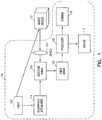
- a representative system 100 for creating a high resolution three-dimensional image of a scene of interest 101 is shown in Fig. 1 .
- a pulsed light source 102 typically a laser, is directed toward target scene 101. Some of the light is reflected back from the scene.
- An array of detectors 104 receives the light from portions of the scene. The distance from the system to the portion of the scene 101 in the field of view of a single detector is determined by the time required for the light to illuminate that portion and then return to the detectors 104.
- imaging system 100 includes a laser 102, optics 103, a detector array 104, a timer circuit 106, a processor 108, storage 110 and a display 112.
- system 100 also includes a resonator/attenuator 114 used to calibrate system 100 in a manner to be described below.
- System 100 measures the round trip time for reflected laser pulse from one or more targets for each of a two-dimensional array of pixels, providing an image with millimeter range accuracy and resolution.
- system 100 includes a pulse generator 130 connected to a laser 132.
- the pulse generator issues an electrical pulse which is turned into an optical pulse by laser 132. If the time from generation of the electrical pulse to the optical pulse is repeatable, transmit time can be determined from generation of the electrical pulse by pulse generator 130. If not, transmit time can be determined based on generation of the optical pulse by laser 132.
- System 100 measures the round trip time for reflected laser pulse from one or more targets for each of a one or two-dimensional array of pixels, providing an image with millimeter range accuracy and resolution.
- optics 134 and detector 136 receive light reflected from object 101.
- Each detector 136 is connected to a timing circuit 138.
- each timing circuit 138 includes a plurality of interpolators.
- An optical pulse is transmitted toward object 101 so that a portion of the optical pulse is reflected from the object as a reflected pulse.
- the reflected pulse passes through optics 134 and falls on detector 136.
- the time for the optical pulse to bounce off object 101 and arrive at one or more of the detectors 136 is used to determine range to object 101.
- detecting arrival of the reflected pulse includes integrating the reflected pulse over a predetermined interval of time to determine a reflected pulse characteristic and recording a value representative of when the reflected pulse arrived at detector 136. Range is then calculated as a function of the transmit time, the receive time and the reflected pulse characteristic.
- system 100 includes a detector 140 and a timing circuit 142 which can be used to determine transmit time for the optical pulse.
- a detector 140 and a timing circuit 142 which can be used to determine transmit time for the optical pulse.
- Fig. 3 One such embodiment is shown in Fig. 3 .
- a portion of the optical pulse is directed to detectors 136. That portion uses detectors 136 and timing circuits 138 to determine a transmit time and amplitude for the optical pulse.
- detector array 104 and timer array 106 are implemented as a hybrid of two chips, an array of detectors connected to an array of processing electronics unit cells. Each detector on one chip is connected to its own processing-electronics unit cell on the other chip. This defines one voxel in the image. Each processing-electronics unit cell on the array contains an identical and unique integrated circuit which can store one or more reflected-pulse transit times and either the associated reflected-pulse energy or peak amplitude. Transit-time and pulse amplitude information for all pixels is read out preferably between laser pulses.
- the array of detectors and their associated processing-electronics unit cells are distributed throughout an integrated circuit. While this has the disadvantage of providing a smaller proportion of surface area to collect photons, it can be produced much more economically since the two chips do not need to be mated.
- a core principle of any pulsed lidar system is to measure the time between when a pulse is emitted and when a reflected pulse is received.
- Light travels at the speed of light, c m , for the medium in which it travels.
- the fundamental problem in a millimeter resolution pulsed lidar is to measure time to an accuracy of a few picoseconds.
- a timing circuit 138 can be used in system 100 of Figs. 1-4 is shown in Fig. 5 .
- the returning light is detected by detector 150 and converted to an electrical signal.
- the signal is amplified by transimpedance amplifier (TIA) 152, and then converted into a signal appropriate to trigger a flip-flop by discriminator 154.
- the output of flip-flop 156 goes high when a first pulse is detected, and the output of flip-flop 158 goes high only when a second pulse is detected.
- the time of arrival of the two pulses is converted to a digital signal by time converters 160 and 162 and read out through multiplexer 168.
- timing circuit 138 includes gated integrators 164 and 166.
- the amplitude of the two pulses is determined by integrating the signal from slightly before the pulse starts until shortly after the pulse ends.
- a peak detector can be employed rather than a gated integrator. While simpler to implement, this is likely to provide poorer performance as the peak of a pulse is not a good monotonic indicator of pulse energy, particularly when the detector is operating in a non-linear region.
- the measurement of pulse intensity is critical in making accurate range measurements when the associated timing measurements are made between times at which the pulses exceed a threshold and the required precision is significantly smaller than the pulse rise time.
- the threshold is exceeded sooner, and this leads to an apparently shorter distance (ranging error).
- An accurate measure of pulse intensity such as provided by a gated integrator, provides an effective means of compensating for this apparent error in range measurement.
- a peak detector can be used to estimate pulse intensity; however this provides much less accurate range compensation - particularly when the detector is operating in saturation.
- the gated integrator can be triggered in advance of the arrival of the received pulse by the introduction of a delay line of a few nanoseconds.
- the introduction of such a delay line at each pixel would be prohibitive.
- each gated integrator block includes a pair of gated integrators which are ping-ponged to find the intensity of each of these pulses.
- each gated integrator can be integrated over a time that is at least as long as the longest pulse that will be observed. When the return pulse is detected, the alternation between integrators is stopped, and the last integrated pulse is utilized to compensate the range measurement.
- reflected pulses are 1-20 ns in length when they reach detector 136. In such an embodiment, one could design gated integrators 164 and 166 to integrate over 20 ns, with an overlap of 10 ns.
- a method of determining the transit time for an optical pulse will be described next.
- the simplest approach to measuring time interval between two pulses is to enable a counter when the first pulse arrives, stop the counter when the second pulse arrives, and record the number of counts.
- the number of counts times the clock period will be the time.
- the basic problem with this is that in order to have a resolution of 1mm, the clock frequency would have to be approximately 200GHz. This is neither economic nor practical for a large array of sensors.
- Timing circuit 138 stretches the time interval two or more times, so that a more modest clock frequency can be utilized to achieve the required accuracy.
- each time converter 160 and 162 includes at least one interpolator.
- An interpolator measures the time between an asynchronous event and a subsequent master clock pulse.
- each interpolator includes an interpolator circuit 180 which charges a capacitor at a different rate than it discharges.
- An example interpolator circuit 180 is shown in Fig. 6 .
- An example timing diagram is shown in Fig. 7
- This interpolator The fundamental concept of this interpolator is to create a linear charging ramp on a capacitor when the first pulse arrives, begin discharging this capacitor at a different rate after a fixed number of master clock pulses, and enable a counter on the master clock pulses until the capacitor arrives at its original state. Implementations of this process have been previously called Nutt interpolators.
- timing circuit 138 counts the number of clock pulses of the master clock that occur between the arrival of the first pulse and the arrival of the second pulse.
- the time intervals T A and T B can be estimated by a pair of interpolators that effectively stretch the time by a potentially large factor, enabling accurate measurement by counting with the same master clock.
- integrating capacitor 182 is held at a high level by upper current source 184.
- flip-flop 186 waits for a pulse and the coarse counter is enabled.
- flip-flop 186 is clocked, and that in turn causes integrating capacitor 182to be discharged by a lower current source 185 at a high rate, and the fine counter is enabled.
- the transition of flip-flop 188 propagates through the synchronizing flip-flops 188 and 190, integrating capacitor 182 is then charged again by upper current source 184.
- the output of comparator 192 shows that the integrating capacitor has returned to its original level, the fine counter is disabled.
- two or more separate interpolator circuits 180 are cascaded, with the discharge of one triggered when the previous capacitor has returned to a threshold value.
- An example timing diagram for an interpolator having two interpolator circuits 180 is shown in Fig. 8 .
- an interpolator includes five or six cascaded interpolator circuits 180; the discharge of one interpolator circuit 180 is triggered when the previous capacitor has returned to a threshold value.
- the clock operates at 100 Mhz and the rate of charging for each capacitor is 8-16 (corresponding to 3 or 4 bits) times the rate of discharging. If the rate of charging is 8 times that of discharging, such an embodiment leads to a total interpolation of 8 ⁇ 5 or 32,768 times the rate of discharging.
- Interpolation capacitors may, for instance, be on the order of 8-20 fF, with the charging/discharging currents about 200-800nA.
- the value of the intensity measurement can be either digitized at the pixel and multiplexed as a digital value or it can be multiplexed as an analog voltage to an off-chip analog-to-digital converter. Nearly identical circuitry will suffice to digitize the intensity as was used to measure the interpolated voltage - a counter will determine how long it takes to reduce the stored voltage to an original value.
- Timing interpolation An alternative approach is to provide a single slope measurement of the timing interpolation, saving the voltage on the interpolator until after all the pixel measurements are performed. At that point the interpolated value can be multiplexed off the chip with an analog multiplexer, rather than a digital multiplexer as provided in the dual slope implementation. These values would then be converted by an off-chip analog-to-digital converter.
- An example timing diagram for such an approach is shown in Fig. 9 .
- a capacitor When a pulse is detected, a capacitor will be charged at a fixed rate until a subsequent transition of the master clock. The value of the voltage on the capacitor will be proportional to the time between the pulse and this clock edge.
- the multiplexer in this case, will transmit an analog voltage off chip.
- system 100 also may include a resonator/attenuator 114 used to calibrate system 100.
- a resonator/attenuator 114 used to calibrate system 100.
- One impediment to making highly accurate measurements with an individual pixel is the variation of circuit properties that can occur during operation, including variations of laser pulse properties, environmental conditions and aging. Additionally, within an array individual pixels may behave differently, and the variation of their behavior may not track with environmental conditions or time. Also, when the detectors operate in saturation, the intensity measurement may not be linear. Consequently it is important to incorporate components which can allow the system to compensate for these behaviors across the array.
- a fiber resonator/attenuator is added to characterize the properties of individual pixels and their variation as a function of pulse properties, environmental conditions, and aging; and the variation of behavior within the array.
- the principle function of this assembly is to provide a known range of signals to the receiver, essentially simulating the circumstances the receiver would experience when presented with a test object but within the confines of the instrument.
- the instrument When in calibration mode, the instrument will be presented with a sequence of pulses from the resonator/attenuator 114, and measured results from this will be subsequently used to adjust the measurements taken from real objects.
- Resonator/attenuator 114 includes a variable attenuator 200, a fiber coupler 202, a fiber resonator 204 and a fiber collimator 206.
- a small sample of pulse from laser 102 is passed through a variable attenuator 200 on its way to the fiber coupler 202.
- the attenuator 200 permits simulating a wide range of return signal amplitudes, and determining their effect on the apparent round trip time delay. It can also be set to prevent the laser pulses from reaching detector array 104 through this path; in that case the only energy reaching the detector array is from a remote object being measured.
- fiber resonator 204 is assembled using an optical fiber 208 and a 2x2 coupler 210, as shown in Fig. 11 .
- Optical fiber 208 can be a multimode fiber if the bandwidth of the laser pulse is small enough, but it will need to be a single mode fiber if the bandwidth of the fiber is large enough to cause significant dispersion over the desired fiber length compared to the required timing precision.
- Coupler 210 distributes the incoming pulse between the two output ports, with any convenient distribution.
- a pulse delivered to the input of a 50-50 coupler would send half the power to each output port, so half the power would be delivered to the detector array, and the other half would be delivered to the input of the coupler, with a delay proportional to the length of the connecting fiber. This would continuously repeat, delivering a sequence of pulses to fiber collimator 206.
- Fiber collimator 204 couples the emerging laser pulse onto detector array 104.
- the emerging pulse it is preferable for the emerging pulse to arrive at every pixel in the detector array simultaneously, but it is acceptable if the time variation across the array is geometrically deterministic and repeatable.
- a bundle 212 with multiple fibers is used to simulate multiple time delays. These can be selected with a set of ranges approximately the same as experienced by the detector when the system is operated to acquire data. Such an approach is shown in Fig. 12 .
- the fiber resonator is either a single mode or multimode fiber with the ends coated so that they are partially reflective.
- This approach has two significant disadvantages over the other approaches: 1) the first pulse arrives faster than subsequent pulses that have to traverse the fiber twice; and 2) the reflective coating on the input facet will attenuate all the pulses, and will be reflected back towards laser 102.
- the number and spacing of the pulses coming from resonator/attenuator 114 will depend on the particular architecture for the resonator. However, the spacing will be highly stable at a particular temperature of the fiber.
- the effective fiber length, corresponding to the spacing between these pulses, can be characterized as a function of temperature. Alternatively, a fiber whose propagation is nearly independent of temperature can be utilized, though this is can be more difficult and expensive to produce.
- the calibrator compensates for the apparent ranges of objects measured in the field.
- timing circuit 106 or 138 will be used to measure the apparent ranges of the pulses coming from resonator/attenuator 114. These values are recorded.
- the fibers in the resonator/attenuator 114 will not change length or refractive index over time.
- the measured ranges of the object will be altered depending on the apparent ranges from the calibration. For instance, if the calibrator measurements suggest that time intervals are all being measured .5% longer, then the same amount will be added to the measurements for the real object.
- the calibrator can also be used to determine variations in measured range due to variations in return intensity. Since the spacing of the pulses from the calibrator is independent of intensity, the attenuation can be varied and both pulse intensity measurements and time interval measurements can be recorded. This can be used to produce a table of measured intensity vs. measured time. This table can then be used as a correction to measurements taken from real objects, so that objects of differing intensity but the same range will appear to have the same range as long as the environmental conditions of the sensor remain unchanged. When the environment does change, a new table of corrections must be acquired. This procedure adds significantly to the system resolution and accuracy
- the laser pulse rise time is comparable to the desired precision, range walk compensation will not be necessary, and the pulse intensity measurement will not be needed.
- the receiving detector array is operated in non-linear Geiger mode as in Marino above, a single received photon can cause a state transition in the receiver. In this case, the measurement of received pulse intensity can only be determined on a statistical basis. However, if the pulse is large enough to have a high likelihood of being detected, then it is most likely that the received photon appears in the rise time of the laser. Thus, if the laser pulse rise time is comparable to the desired precision, no pulse intensity measurement will be needed to compensate for any apparent range walk. So to achieve 5mm resolution, a laser pulse with a rise time shorter than 35psec will be adequate to ensure that no range walk correction will be required.
- the correction table is created in the factory, the corrections are unlikely to remain constant over time and temperature to millimeter accuracy, principally because of variations in component parameters with temperature or aging.
- the procedure would have to be applied periodically. However, the procedure cannot be conveniently applied in the field, as suitable flat surfaces are unlikely to be conveniently available. Even if suitable fixtures were available, it would be unknown when or how often they should be applied. Further, the system operator would be required to execute a special procedure, and his future results would be dependent on how well the procedure was followed.
- the resonator array imposes the same pulse delay pattern across the detector array every time since the geometry of the components will be unchanged.
- a single factory calibration of the apparent differences across the array can be supplemented with the apparent differences at the moment the array uniformity is being field evaluated, and the sum of these corrections can be applied to every pixel when applied to real objects.
- timing interpolators are designed to provide an accurate, linear measure of the elapsed time between asynchronous events and system clock pulses
- real circuits can only provide an approximation. The difference can become exceedingly important when attempting to make measurements with picosecond precision, and also when the interpolation ratios are large.
- a two step process is applied to obtain enhanced range information on inclined surfaces While the ranges to inclined surfaces will be underestimated, the normal to these surfaces will be well approximated if adjacent samples are on the same region. Therefore, a good approximation of the surface normal can be obtained uncorrected data. Then, in a second step, the range to the center of the laser spot can be determined by increasing the first range estimate in accordance with this normal estimate.
- o(x,y) represent the range distribution associated with an object
- r(x,y) represent the range distribution associated with a blurred image of that object.
- the blur the image has been subjected to is a linear, space-invariant transformation, describable by a known space-invariant point-spread function s(x,y).
- the present invention provides a device for three dimensional imaging of objects using a single laser pulse. It overcomes the problems of prior systems in providing millimeter accuracy and resolution.
- the device comprises a pulsed light source, means for projecting the light towards the object, optics for collecting the reflected light, sensors for detecting the reflected light, conditioning for analog signals produced by the sensors, processors for recording intensity and timing data from the sensors, and a computer and software for converting the sensor data to a highly accurate three dimensional image.
- An array of optics and electromechanical devices are operated in concert with an algorithm to calibrate the system in situ to provide highly accurate measurements.
- computer and "processor” are defined to include any digital or analog data processing unit. Examples include any personal computer, workstation, set top box, mainframe, server, supercomputer, laptop or personal digital assistant capable of embodying the inventions described herein.
- Examples of articles comprising computer readable media are floppy disks, hard drives, CD-ROM or DVD media or any other read-write or read-only memory device.
Landscapes
- Engineering & Computer Science (AREA)
- Physics & Mathematics (AREA)
- Computer Networks & Wireless Communication (AREA)
- General Physics & Mathematics (AREA)
- Radar, Positioning & Navigation (AREA)
- Remote Sensing (AREA)
- Electromagnetism (AREA)
- Optical Radar Systems And Details Thereof (AREA)
- Length Measuring Devices By Optical Means (AREA)
- Measurement Of Optical Distance (AREA)
Claims (6)
- Verfahren zum Abbilden eines Objekts, umfassend:Montieren eines Arrays von Detektoren (104, 136) in einer Bildebene;Verbinden jedes Detektors in dem Array von Detektoren (104, 136) mit einer Zeitgeberschaltung (106, 138) mit einem oder mehreren Interpolatoren, wobei jeder Interpolator zwei oder mehr Interpolatorschaltungen (180) umfasst, die in einer Kaskade verbunden sind, wobei jede Interpolatorschaltung (180) dazu konfiguriert ist, einen Kondensator mit einer anderen Rate zu laden, als sie ihn entlädt;Übertragen eines optischen Pulses zu einem Objekt (101) hin, so dass ein Teil des optischen Pulses von dem Objekt (101) als ein reflektierter Puls reflektiert wird, wobei das Übertragen des optischen Pulses das Aufzeichnen eines ersten Werts umfasst, wobei der erste Wert darstellt, wann der optische Puls zu dem Objekt hin übertragen wurde;Erfassen des Ankommens des reflektierten Pulses an einem oder mehreren Detektoren innerhalb des Arrays von Detektoren (104, 136), wobei das Erfassen des Ankommens des reflektierten Pulses umfasst:Bestimmen eines Charakteristikums des reflektierten Pulses, das die Amplitude des reflektierten Pulses darstellt; undAufzeichnen eines zweiten Werts, wobei der zweite Wert darstellt, wann der reflektierte Puls an dem Detektor ankam, und wobei das Aufzeichnen des zweiten Werts das Initiieren einer ersten Interpolatorschaltung bei Ankommen des reflektierten Pulses an dem Detektor und das Initiieren einer zweiten Interpolatorschaltung, nachdem der Kondensator der ersten Interpolatorschaltung eine vorherbestimmte Spannung erreicht hat, umfasst; undMessen einer Entfernung zu dem Objekt in Abhängigkeit von dem ersten und dem zweiten Wert und dem Charakteristikum des reflektierten Pulses.
- Verfahren nach Anspruch 1, wobei das Bestimmen eines Charakteristikums des reflektierten Pulses das Integrieren des reflektierten Pulses über ein vorherbestimmtes Zeitintervall umfasst.
- Verfahren nach Anspruch 1, wobei das Bestimmen eines Charakteristikums des reflektierten Pulses das Erfassen einer Spitzenamplitude umfasst.
- Verfahren nach Anspruch 1, wobei das Aufzeichnen eines zweiten Werts das Überwachen des Detektors, um zu erfassen, wann der reflektierte Puls einen Grenzwert durchläuft, das Aufzeichnen einer Erfassungszeit, die dem entspricht, wann der reflektierte Puls den Grenzwert durchlief, und das Korrigieren der Erfassungszeit in Abhängigkeit von dem Charakteristikum des reflektierten Pulses umfasst.
- Verfahren nach Anspruch 1, wobei das Übertragen eines optischen Pulses das Leiten eines Teils des optischen Pulses zu einem Detektor umfasst und wobei das Aufzeichnen eines ersten Werts das Erfassen des Ankommens des Teils des optischen Pulses an dem Detektor umfasst.
- System (100) zum Abbilden eines Objekts, umfassend Mittel, die dazu konfiguriert sind, die Verfahrensschritte nach einem der Ansprüche 1 bis 5 durchzuführen.
Applications Claiming Priority (2)
| Application Number | Priority Date | Filing Date | Title |
|---|---|---|---|
| US10/886,073 US7236235B2 (en) | 2004-07-06 | 2004-07-06 | System and method for determining range in 3D imaging systems |
| EP05764423A EP1782099B1 (de) | 2004-07-06 | 2005-07-06 | Entfernungsbestimmung in 3d-abbildungssystemen |
Related Parent Applications (2)
| Application Number | Title | Priority Date | Filing Date |
|---|---|---|---|
| EP05764423A Division EP1782099B1 (de) | 2004-07-06 | 2005-07-06 | Entfernungsbestimmung in 3d-abbildungssystemen |
| EP05764423.9 Division | 2005-07-06 |
Publications (3)
| Publication Number | Publication Date |
|---|---|
| EP2357491A2 EP2357491A2 (de) | 2011-08-17 |
| EP2357491A3 EP2357491A3 (de) | 2012-05-16 |
| EP2357491B1 true EP2357491B1 (de) | 2017-08-30 |
Family
ID=35064673
Family Applications (5)
| Application Number | Title | Priority Date | Filing Date |
|---|---|---|---|
| EP05764423A Revoked EP1782099B1 (de) | 2004-07-06 | 2005-07-06 | Entfernungsbestimmung in 3d-abbildungssystemen |
| EP11162886A Withdrawn EP2357492A3 (de) | 2004-07-06 | 2005-07-06 | Entfernungsbestimmung in 3D-Abbildungssystemen |
| EP11162885A Withdrawn EP2348333A3 (de) | 2004-07-06 | 2005-07-06 | Entfernungsbestimmung in 3D-Abbildungssystemen |
| EP11162884A Withdrawn EP2348332A3 (de) | 2004-07-06 | 2005-07-06 | Entfernungsbestimmung in 3D-Abbildungssystemen |
| EP11162883.0A Active EP2357491B1 (de) | 2004-07-06 | 2005-07-06 | Entfernungsbestimmung in 3d-abbildungssystemen |
Family Applications Before (4)
| Application Number | Title | Priority Date | Filing Date |
|---|---|---|---|
| EP05764423A Revoked EP1782099B1 (de) | 2004-07-06 | 2005-07-06 | Entfernungsbestimmung in 3d-abbildungssystemen |
| EP11162886A Withdrawn EP2357492A3 (de) | 2004-07-06 | 2005-07-06 | Entfernungsbestimmung in 3D-Abbildungssystemen |
| EP11162885A Withdrawn EP2348333A3 (de) | 2004-07-06 | 2005-07-06 | Entfernungsbestimmung in 3D-Abbildungssystemen |
| EP11162884A Withdrawn EP2348332A3 (de) | 2004-07-06 | 2005-07-06 | Entfernungsbestimmung in 3D-Abbildungssystemen |
Country Status (5)
| Country | Link |
|---|---|
| US (3) | US7236235B2 (de) |
| EP (5) | EP1782099B1 (de) |
| JP (1) | JP5325420B2 (de) |
| CN (5) | CN102411146A (de) |
| WO (1) | WO2006014470A2 (de) |
Families Citing this family (92)
| Publication number | Priority date | Publication date | Assignee | Title |
|---|---|---|---|---|
| US7697748B2 (en) * | 2004-07-06 | 2010-04-13 | Dimsdale Engineering, Llc | Method and apparatus for high resolution 3D imaging as a function of camera position, camera trajectory and range |
| US7236235B2 (en) * | 2004-07-06 | 2007-06-26 | Dimsdale Engineering, Llc | System and method for determining range in 3D imaging systems |
| US8294809B2 (en) | 2005-05-10 | 2012-10-23 | Advanced Scientific Concepts, Inc. | Dimensioning system |
| JP2007255977A (ja) * | 2006-03-22 | 2007-10-04 | Nissan Motor Co Ltd | 物体検出方法および物体検出装置 |
| CN100365436C (zh) * | 2006-04-26 | 2008-01-30 | 浙江大学 | 一种区域化照明探测方法 |
| JP5073273B2 (ja) * | 2006-11-21 | 2012-11-14 | スタンレー電気株式会社 | 遠近判定方法およびその装置 |
| US7855778B2 (en) * | 2007-04-27 | 2010-12-21 | Robert Bosch Company Limited | Method and apparatus for locating and measuring the distance to a target |
| DE102007034950B4 (de) * | 2007-07-26 | 2009-10-29 | Siemens Ag | Verfahren zur selektiven sicherheitstechnischen Überwachung von Flugstrom-Vergasungsreaktoren |
| KR20090025959A (ko) * | 2007-09-07 | 2009-03-11 | 삼성전자주식회사 | 거리 측정 방법 및 장치 |
| US7945408B2 (en) | 2007-09-20 | 2011-05-17 | Voxis, Inc. | Time delay estimation |
| WO2009078002A1 (en) * | 2007-12-19 | 2009-06-25 | Microsoft International Holdings B.V. | 3d camera and methods of gating thereof |
| US8077294B1 (en) | 2008-01-17 | 2011-12-13 | Ball Aerospace & Technologies Corp. | Optical autocovariance lidar |
| US8119971B2 (en) * | 2008-01-17 | 2012-02-21 | Ball Corporation | Pulse data recorder in which a value held by a bit of a memory is determined by a state of a switch |
| FR2927196B1 (fr) * | 2008-02-01 | 2010-02-12 | Commissariat Energie Atomique | Pixel pour imagerie active 3d. |
| US7961301B2 (en) * | 2008-05-09 | 2011-06-14 | Ball Aerospace & Technologies Corp. | Flash LADAR system |
| US9041915B2 (en) | 2008-05-09 | 2015-05-26 | Ball Aerospace & Technologies Corp. | Systems and methods of scene and action capture using imaging system incorporating 3D LIDAR |
| US7929215B1 (en) | 2009-02-20 | 2011-04-19 | Ball Aerospace & Technologies Corp. | Field widening lens |
| US20110285981A1 (en) * | 2010-05-18 | 2011-11-24 | Irvine Sensors Corporation | Sensor Element and System Comprising Wide Field-of-View 3-D Imaging LIDAR |
| US8306273B1 (en) | 2009-12-28 | 2012-11-06 | Ball Aerospace & Technologies Corp. | Method and apparatus for LIDAR target identification and pose estimation |
| US8587637B1 (en) * | 2010-05-07 | 2013-11-19 | Lockheed Martin Corporation | Three dimensional ladar imaging and methods using voxels |
| US9052381B2 (en) | 2010-05-07 | 2015-06-09 | Flir Systems, Inc. | Detector array for high speed sampling of an optical pulse |
| TWI448666B (zh) | 2010-06-15 | 2014-08-11 | Pixart Imaging Inc | 依據環境溫度以校正測距裝置所量測之待測物之待測距離之校正方法與其相關裝置 |
| CN102472622B (zh) * | 2010-06-17 | 2015-12-02 | 松下电器产业株式会社 | 距离推定装置以及距离推定方法 |
| CN102346030B (zh) * | 2010-07-30 | 2016-09-14 | 原相科技股份有限公司 | 依据温度校正测距装置量测的待测距离的方法及其装置 |
| US8736818B2 (en) | 2010-08-16 | 2014-05-27 | Ball Aerospace & Technologies Corp. | Electronically steered flash LIDAR |
| KR101669412B1 (ko) * | 2010-11-01 | 2016-10-26 | 삼성전자주식회사 | 3d 카메라를 위한 깊이 정보 측정 방법 및 장치 |
| US8619239B2 (en) * | 2011-01-28 | 2013-12-31 | Analog Modules Inc. | Accuracy of a laser rangefinder receiver |
| US9069061B1 (en) | 2011-07-19 | 2015-06-30 | Ball Aerospace & Technologies Corp. | LIDAR with analog memory |
| US8913784B2 (en) | 2011-08-29 | 2014-12-16 | Raytheon Company | Noise reduction in light detection and ranging based imaging |
| US8744126B1 (en) | 2012-03-07 | 2014-06-03 | Ball Aerospace & Technologies Corp. | Morphology based hazard detection |
| US9823351B2 (en) | 2012-12-18 | 2017-11-21 | Uber Technologies, Inc. | Multi-clad fiber based optical apparatus and methods for light detection and ranging sensors |
| CN103033818A (zh) * | 2012-12-25 | 2013-04-10 | 中国电子科技集团公司第十三研究所 | 一种抗云雾干扰激光探测装置 |
| US9619934B2 (en) * | 2013-01-21 | 2017-04-11 | Vricon Systems Aktiebolag | Method and an apparatus for estimating values for a set of parameters of an imaging system |
| GB2510891A (en) * | 2013-02-18 | 2014-08-20 | St Microelectronics Res & Dev | Apparatus |
| JP2013137324A (ja) * | 2013-03-07 | 2013-07-11 | Toyota Motor Corp | 画像取得装置及び方法 |
| US9470520B2 (en) | 2013-03-14 | 2016-10-18 | Apparate International C.V. | LiDAR scanner |
| EP2806248B1 (de) * | 2013-04-12 | 2018-09-12 | Leica Geosystems AG | Verfahren zur Kalibrierung einer Erfassungseinrichtung und Erfassungseinrichtung |
| CN104416285B (zh) * | 2013-08-19 | 2016-03-30 | 昆山国显光电有限公司 | 一种定量修补装置及其定量修补方法 |
| US10203399B2 (en) | 2013-11-12 | 2019-02-12 | Big Sky Financial Corporation | Methods and apparatus for array based LiDAR systems with reduced interference |
| CA2931055C (en) | 2013-11-22 | 2022-07-12 | Ottomotto Llc | Lidar scanner calibration |
| CN103698770A (zh) * | 2013-12-11 | 2014-04-02 | 中国科学院长春光学精密机械与物理研究所 | 基于fpga芯片的多通道激光回波时间测量系统 |
| CN103760567B (zh) * | 2014-01-27 | 2016-06-15 | 中国科学院半导体研究所 | 一种具有测距功能的被动成像系统及其测距方法 |
| US9110154B1 (en) * | 2014-02-19 | 2015-08-18 | Raytheon Company | Portable programmable ladar test target |
| US9360554B2 (en) | 2014-04-11 | 2016-06-07 | Facet Technology Corp. | Methods and apparatus for object detection and identification in a multiple detector lidar array |
| EP3195010A4 (de) | 2014-08-15 | 2018-04-11 | Aeye, Inc. | Verfahren und systeme zur ladar-übertragung |
| US9658336B2 (en) | 2014-08-20 | 2017-05-23 | Omnivision Technologies, Inc. | Programmable current source for a time of flight 3D image sensor |
| US9720076B2 (en) * | 2014-08-29 | 2017-08-01 | Omnivision Technologies, Inc. | Calibration circuitry and method for a time of flight imaging system |
| EP2998700B2 (de) | 2014-09-18 | 2022-12-21 | Hexagon Technology Center GmbH | Elektrooptischer Distanzmesser und Distanzmessverfahren |
| DE102014117097B3 (de) * | 2014-11-21 | 2016-01-21 | Odos Imaging Ltd. | Abstandsmessvorrichtung und Verfahren zum Bestimmen eines Abstands |
| TWI565960B (zh) * | 2014-11-21 | 2017-01-11 | 專家科技有限公司 | 測距方法、測距裝置、定位裝置與定位方法 |
| TWI574026B (zh) * | 2014-11-21 | 2017-03-11 | 專家科技有限公司 | 測距方法、測距裝置、定位裝置與定位方法 |
| US10036801B2 (en) | 2015-03-05 | 2018-07-31 | Big Sky Financial Corporation | Methods and apparatus for increased precision and improved range in a multiple detector LiDAR array |
| US10408926B2 (en) * | 2015-09-18 | 2019-09-10 | Qualcomm Incorporated | Implementation of the focal plane 2D APD array for hyperion lidar system |
| WO2017058901A1 (en) | 2015-09-28 | 2017-04-06 | Ball Aerospace & Technologies Corp. | Differential absorption lidar |
| US11131756B2 (en) * | 2015-09-29 | 2021-09-28 | Qualcomm Incorporated | LIDAR system with reflected signal strength measurement |
| US10042159B2 (en) | 2016-02-18 | 2018-08-07 | Aeye, Inc. | Ladar transmitter with optical field splitter/inverter |
| US10754015B2 (en) | 2016-02-18 | 2020-08-25 | Aeye, Inc. | Adaptive ladar receiver |
| US20170242104A1 (en) | 2016-02-18 | 2017-08-24 | Aeye, Inc. | Ladar Transmitter with Induced Phase Drift for Improved Gaze on Scan Area Portions |
| US9933513B2 (en) | 2016-02-18 | 2018-04-03 | Aeye, Inc. | Method and apparatus for an adaptive ladar receiver |
| CZ306524B6 (cs) * | 2016-02-20 | 2017-02-22 | MAXPROGRES, s.r.o. | Metoda monitorování pomocí kamerového systému s prostorovou detekcí pohybu |
| EP3423858B1 (de) * | 2016-02-29 | 2023-12-06 | nLIGHT, Inc. | System und verfahren zur 3d-bildgebung |
| US9866816B2 (en) | 2016-03-03 | 2018-01-09 | 4D Intellectual Properties, Llc | Methods and apparatus for an active pulsed 4D camera for image acquisition and analysis |
| US10451740B2 (en) * | 2016-04-26 | 2019-10-22 | Cepton Technologies, Inc. | Scanning lidar systems for three-dimensional sensing |
| CN105954733B (zh) * | 2016-06-17 | 2018-11-13 | 南京理工大学 | 基于光子飞行时间相关性的时域滤波方法 |
| CN106500604A (zh) * | 2016-11-10 | 2017-03-15 | 西安科技大学 | 基于光影的平面凸点高度测量装置及方法 |
| EP3339901B1 (de) * | 2016-12-21 | 2019-04-24 | Hexagon Technology Center GmbH | Laserdistanzmessmodul mit adc-fehlerkompensation durch variation der samplingzeitpunkte |
| CN110431439A (zh) | 2017-02-17 | 2019-11-08 | 艾耶股份有限公司 | 用于激光雷达脉冲冲突消除的方法和系统 |
| US10556585B1 (en) * | 2017-04-13 | 2020-02-11 | Panosense Inc. | Surface normal determination for LIDAR range samples by detecting probe pulse stretching |
| CN107101596A (zh) * | 2017-06-12 | 2017-08-29 | 昆山锐芯微电子有限公司 | 距离传感器和3d图像传感器 |
| US10739140B2 (en) | 2017-09-08 | 2020-08-11 | Apple Inc. | Iterative estimation of non-holonomic constraints in an inertial navigation system |
| KR102429879B1 (ko) * | 2017-09-13 | 2022-08-05 | 삼성전자주식회사 | 라이다 장치 및 이의 동작 방법 |
| US11002857B2 (en) | 2017-09-15 | 2021-05-11 | Aeye, Inc. | Ladar system with intelligent selection of shot list frames based on field of view data |
| EP3502744B1 (de) * | 2017-12-20 | 2020-04-22 | Leica Geosystems AG | Nahfeldimpulsdetektion |
| US10921245B2 (en) | 2018-06-08 | 2021-02-16 | Ball Aerospace & Technologies Corp. | Method and systems for remote emission detection and rate determination |
| US11493615B2 (en) * | 2018-09-11 | 2022-11-08 | Velodyne Lidar Usa, Inc. | Systems and methods for detecting an electromagnetic signal in a constant interference environment |
| US11061119B2 (en) | 2018-10-10 | 2021-07-13 | Sensors Unlimited, Inc. | Pixels for time of flight (TOF) imaging |
| JP2020060433A (ja) * | 2018-10-10 | 2020-04-16 | ソニーセミコンダクタソリューションズ株式会社 | 測距システム、キャリブレーション方法、プログラム、及び電子機器 |
| US10656277B1 (en) | 2018-10-25 | 2020-05-19 | Aeye, Inc. | Adaptive control of ladar system camera using spatial index of prior ladar return data |
| US11585909B2 (en) * | 2018-11-02 | 2023-02-21 | Waymo Llc | Laser safety comparator |
| EP3696568A1 (de) * | 2019-02-15 | 2020-08-19 | Trimble AB | Verbesserter elektronischer entfernungsmesser |
| US11681030B2 (en) * | 2019-03-05 | 2023-06-20 | Waymo Llc | Range calibration of light detectors |
| US10656272B1 (en) | 2019-04-24 | 2020-05-19 | Aeye, Inc. | Ladar system and method with polarized receivers |
| JP7240947B2 (ja) | 2019-05-09 | 2023-03-16 | 株式会社アドバンテスト | 光学試験用装置 |
| EP3816657B1 (de) * | 2019-10-29 | 2024-04-24 | Hexagon Technology Center GmbH | Mehrstrahlmessvorrichtung zur 3d-abtastung einer umgebung mit nahtlos gestapelten empfangsmodulen |
| CN111398976B (zh) * | 2020-04-01 | 2022-08-23 | 宁波飞芯电子科技有限公司 | 探测装置及方法 |
| US11474212B1 (en) | 2021-03-26 | 2022-10-18 | Aeye, Inc. | Hyper temporal lidar with dynamic laser control and shot order simulation |
| US11630188B1 (en) | 2021-03-26 | 2023-04-18 | Aeye, Inc. | Hyper temporal lidar with dynamic laser control using safety models |
| US11467263B1 (en) | 2021-03-26 | 2022-10-11 | Aeye, Inc. | Hyper temporal lidar with controllable variable laser seed energy |
| US11822016B2 (en) | 2021-03-26 | 2023-11-21 | Aeye, Inc. | Hyper temporal lidar using multiple matched filters to orient a lidar system to a frame of reference |
| US20230044929A1 (en) | 2021-03-26 | 2023-02-09 | Aeye, Inc. | Multi-Lens Lidar Receiver with Multiple Readout Channels |
| US11635495B1 (en) | 2021-03-26 | 2023-04-25 | Aeye, Inc. | Hyper temporal lidar with controllable tilt amplitude for a variable amplitude scan mirror |
| US11686845B2 (en) | 2021-03-26 | 2023-06-27 | Aeye, Inc. | Hyper temporal lidar with controllable detection intervals based on regions of interest |
Family Cites Families (58)
| Publication number | Priority date | Publication date | Assignee | Title |
|---|---|---|---|---|
| US3983481A (en) * | 1975-08-04 | 1976-09-28 | Ortec Incorporated | Digital intervalometer |
| US4167328A (en) * | 1977-09-28 | 1979-09-11 | Westinghouse Electric Corp. | Passive optical range simulator device |
| DE3034942C2 (de) * | 1980-09-16 | 1982-10-28 | Siemens AG, 1000 Berlin und 8000 München | Meßeinrichtung zur Bestimmung des Extinktionswertes von Laserentfernungsmessern |
| DE3034922C2 (de) * | 1980-09-16 | 1982-11-25 | Siemens AG, 1000 Berlin und 8000 München | Justier- und Prüfeinrichtung für ein Laserentfernungsmeßsystem |
| CH641308B (de) * | 1982-07-13 | Wild Heerbrugg Ag | Vorrichtung zur laufzeitmessung von impulssignalen. | |
| GB2247583B (en) * | 1982-11-05 | 1992-05-27 | Hughes Aircraft Co | Vector filter for optical moving target detection |
| JPS62288597A (ja) * | 1986-06-06 | 1987-12-15 | Yokogawa Electric Corp | 時間計測装置 |
| JPS63274889A (ja) * | 1987-05-07 | 1988-11-11 | Kasuga Denki Kk | 光波距離計の受信装置 |
| JPH0476480A (ja) * | 1990-07-17 | 1992-03-11 | Nikon Corp | パルス測距装置 |
| DE4109844C1 (en) | 1991-03-26 | 1992-06-11 | Eltro Gmbh, Gesellschaft Fuer Strahlungstechnik, 6900 Heidelberg, De | Laser range finder with fibre=optic propagation time component - couples two glass fibres to photodiode, one being in closed ring form or bounded at both sides by reflectors |
| DE69215760T2 (de) * | 1991-06-10 | 1998-02-05 | Eastman Kodak Co | Kreuzkorrelationsausrichtsystem für einen Bildsensor |
| US5463443A (en) | 1992-03-06 | 1995-10-31 | Nikon Corporation | Camera for preventing camera shake |
| US5446529A (en) * | 1992-03-23 | 1995-08-29 | Advanced Scientific Concepts, Inc. | 3D imaging underwater laser radar |
| US6133989A (en) * | 1993-02-09 | 2000-10-17 | Advanced Scientific Concepts, Inc. | 3D imaging laser radar |
| DE4304290C1 (de) * | 1993-02-12 | 1994-03-03 | Sick Optik Elektronik Erwin | Vorrichtung zur Messung der Laufzeit von elektromagnetischen Wellen |
| JPH06289127A (ja) * | 1993-03-31 | 1994-10-18 | Mazda Motor Corp | 距離計測装置 |
| GB2292605B (en) | 1994-08-24 | 1998-04-08 | Guy Richard John Fowler | Scanning arrangement and method |
| JP3294726B2 (ja) * | 1994-12-20 | 2002-06-24 | 本田技研工業株式会社 | レーダ装置 |
| EP0804714A4 (de) * | 1995-01-19 | 1999-05-12 | Laser Technology Inc | Laserentfernungsmesser |
| WO1996024216A1 (en) | 1995-01-31 | 1996-08-08 | Transcenic, Inc. | Spatial referenced photography |
| JPH09189766A (ja) * | 1996-01-09 | 1997-07-22 | Nikon Corp | 時間・電圧変換回路及び距離測定装置 |
| KR100509128B1 (ko) * | 1996-04-01 | 2005-08-18 | 록히드 마틴 코포레이션 | 화상 포커싱 방법 및 장치 |
| US5988862A (en) * | 1996-04-24 | 1999-11-23 | Cyra Technologies, Inc. | Integrated system for quickly and accurately imaging and modeling three dimensional objects |
| US5892575A (en) * | 1996-05-10 | 1999-04-06 | Massachusetts Institute Of Technology | Method and apparatus for imaging a scene using a light detector operating in non-linear geiger-mode |
| US5790241A (en) | 1996-08-07 | 1998-08-04 | The United States Of America As Represented By The Secretary Of The Army | Laser rangefinder |
| JPH10153660A (ja) * | 1996-11-22 | 1998-06-09 | Olympus Optical Co Ltd | 距離測定装置 |
| JP3076527B2 (ja) * | 1997-02-14 | 2000-08-14 | 株式会社イースタン | 配線基板 |
| US6420698B1 (en) * | 1997-04-24 | 2002-07-16 | Cyra Technologies, Inc. | Integrated system for quickly and accurately imaging and modeling three-dimensional objects |
| JPH1123697A (ja) * | 1997-07-04 | 1999-01-29 | Nissan Motor Co Ltd | レーダ装置 |
| JP3860412B2 (ja) * | 1997-12-23 | 2006-12-20 | シーメンス アクチエンゲゼルシヤフト | 3次元距離画像を撮影するための方法及び装置 |
| US6094215A (en) * | 1998-01-06 | 2000-07-25 | Intel Corporation | Method of determining relative camera orientation position to create 3-D visual images |
| US6176837B1 (en) * | 1998-04-17 | 2001-01-23 | Massachusetts Institute Of Technology | Motion tracking system |
| CA2300400A1 (en) | 1999-03-22 | 2000-09-22 | Michael George Taranowski | Electronic optical target ranging and imaging |
| US6522395B1 (en) * | 1999-04-30 | 2003-02-18 | Canesta, Inc. | Noise reduction techniques suitable for three-dimensional information acquirable with CMOS-compatible image sensor ICS |
| US6323942B1 (en) * | 1999-04-30 | 2001-11-27 | Canesta, Inc. | CMOS-compatible three-dimensional image sensor IC |
| US6619406B1 (en) * | 1999-07-14 | 2003-09-16 | Cyra Technologies, Inc. | Advanced applications for 3-D autoscanning LIDAR system |
| US6448572B1 (en) * | 1999-09-29 | 2002-09-10 | Innovative Technology Licensing, Llc | Ranging three-dimensional laser imager and method |
| US6414746B1 (en) * | 1999-11-24 | 2002-07-02 | Advanced Scientific Concepts, Inc. | 3-D imaging multiple target laser radar |
| US6535114B1 (en) | 2000-03-22 | 2003-03-18 | Toyota Jidosha Kabushiki Kaisha | Method and apparatus for environment recognition |
| AU2001272980A1 (en) | 2000-06-23 | 2002-01-08 | Sportvision, Inc. | Gps based tracking system |
| US6664529B2 (en) * | 2000-07-19 | 2003-12-16 | Utah State University | 3D multispectral lidar |
| US6535275B2 (en) * | 2000-08-09 | 2003-03-18 | Dialog Semiconductor Gmbh | High resolution 3-D imaging range finder |
| US7233351B1 (en) | 2001-02-23 | 2007-06-19 | Nextengine, Inc. | Method for high resolution incremental imaging |
| DE10112833C1 (de) * | 2001-03-16 | 2003-03-13 | Hilti Ag | Verfahren und Einrichtung zur elektrooptischen Distanzmessung |
| DE10143107A1 (de) | 2001-09-03 | 2003-03-20 | Sick Ag | Optoelektronische Entfernungsmeßeinrichtung |
| US6583863B1 (en) * | 2001-10-15 | 2003-06-24 | The Regents Of The University Of California | Single photon imaging and timing array sensor apparatus and method |
| US6759979B2 (en) | 2002-01-22 | 2004-07-06 | E-Businesscontrols Corp. | GPS-enhanced system and method for automatically capturing and co-registering virtual models of a site |
| FR2836215B1 (fr) * | 2002-02-21 | 2004-11-05 | Yodea | Systeme et procede de modelisation et de restitution tridimensionnelle d'un objet |
| US6810207B2 (en) | 2002-05-13 | 2004-10-26 | Olympus Corporation | Camera |
| JP3668470B2 (ja) | 2002-08-21 | 2005-07-06 | 積水ハウス株式会社 | 仮設トイレ囲い |
| DE10256659A1 (de) * | 2002-12-04 | 2004-07-08 | Siemens Ag | Engabevorrichtung zur Orientierung in einer dreidimensionalen Visualisierung, Verfahren zur Visualisierung von dreidimensionalen Datensätzen, Darstellungsvorrichtung zur Darstellung einer Visualisierung von dreidimensionalen Datensätzen, Verfahren zum Betrieb eines bildgebenden medizinischen Üntersuchungsgeräts und Verfahren zur graphischen Positionierung einer mittels eines bildgebenden medizinischen Untersuchungsgeräts zu messenden Schicht in einem dreidimensionalen Datensatz einer Vorbereitungsmessung |
| KR100464054B1 (ko) | 2002-12-27 | 2005-01-03 | 엘지전자 주식회사 | 일체형 캐비넷/터브를 구비한 드럼 세탁기 |
| US7697748B2 (en) * | 2004-07-06 | 2010-04-13 | Dimsdale Engineering, Llc | Method and apparatus for high resolution 3D imaging as a function of camera position, camera trajectory and range |
| US7236235B2 (en) | 2004-07-06 | 2007-06-26 | Dimsdale Engineering, Llc | System and method for determining range in 3D imaging systems |
| JP4866748B2 (ja) | 2007-01-24 | 2012-02-01 | 東芝機械株式会社 | シート成形装置 |
| JP2009189766A (ja) | 2008-02-17 | 2009-08-27 | Tadashi Imai | 心肺停止蘇生用マスク装置 |
| JP5379469B2 (ja) | 2008-12-25 | 2013-12-25 | 古河電気工業株式会社 | 薬液処理方法 |
| KR101046138B1 (ko) | 2009-07-17 | 2011-07-01 | 삼성전기주식회사 | 다층 배선판 및 그 제조방법 |
-
2004
- 2004-07-06 US US10/886,073 patent/US7236235B2/en active Active
-
2005
- 2005-07-06 CN CN2011102409353A patent/CN102411146A/zh active Pending
- 2005-07-06 CN CN2011102408859A patent/CN102411144A/zh active Pending
- 2005-07-06 CN CN2005800292672A patent/CN101027574B/zh not_active Expired - Fee Related
- 2005-07-06 EP EP05764423A patent/EP1782099B1/de not_active Revoked
- 2005-07-06 EP EP11162886A patent/EP2357492A3/de not_active Withdrawn
- 2005-07-06 CN CN2011102409207A patent/CN102411145A/zh active Pending
- 2005-07-06 EP EP11162885A patent/EP2348333A3/de not_active Withdrawn
- 2005-07-06 JP JP2007520459A patent/JP5325420B2/ja active Active
- 2005-07-06 WO PCT/US2005/023922 patent/WO2006014470A2/en active Application Filing
- 2005-07-06 EP EP11162884A patent/EP2348332A3/de not_active Withdrawn
- 2005-07-06 EP EP11162883.0A patent/EP2357491B1/de active Active
- 2005-07-06 CN CN201110240938.7A patent/CN102426364B/zh not_active Expired - Fee Related
-
2007
- 2007-03-26 US US11/691,256 patent/US7453553B2/en active Active
-
2008
- 2008-11-17 US US12/272,095 patent/US8547532B2/en active Active
Non-Patent Citations (1)
| Title |
|---|
| None * |
Also Published As
| Publication number | Publication date |
|---|---|
| US7453553B2 (en) | 2008-11-18 |
| EP2348333A3 (de) | 2012-05-30 |
| CN101027574A (zh) | 2007-08-29 |
| US8547532B2 (en) | 2013-10-01 |
| EP1782099A2 (de) | 2007-05-09 |
| WO2006014470A3 (en) | 2006-03-09 |
| EP2348333A2 (de) | 2011-07-27 |
| JP2008506115A (ja) | 2008-02-28 |
| EP2357492A2 (de) | 2011-08-17 |
| US20070252974A1 (en) | 2007-11-01 |
| EP2357492A3 (de) | 2012-05-30 |
| CN102411146A (zh) | 2012-04-11 |
| US7236235B2 (en) | 2007-06-26 |
| JP5325420B2 (ja) | 2013-10-23 |
| CN102411144A (zh) | 2012-04-11 |
| EP2357491A2 (de) | 2011-08-17 |
| CN102411145A (zh) | 2012-04-11 |
| EP2357491A3 (de) | 2012-05-16 |
| EP2348332A2 (de) | 2011-07-27 |
| US20060007422A1 (en) | 2006-01-12 |
| CN102426364B (zh) | 2014-01-01 |
| CN102426364A (zh) | 2012-04-25 |
| EP1782099B1 (de) | 2012-12-05 |
| EP2348332A3 (de) | 2012-12-05 |
| WO2006014470A2 (en) | 2006-02-09 |
| US20090076758A1 (en) | 2009-03-19 |
| CN101027574B (zh) | 2011-10-19 |
Similar Documents
| Publication | Publication Date | Title |
|---|---|---|
| EP2357491B1 (de) | Entfernungsbestimmung in 3d-abbildungssystemen | |
| US7991222B2 (en) | Method and apparatus for high resolution 3D imaging as a function of camera position, camera trajectory and range | |
| US10416293B2 (en) | Histogram readout method and circuit for determining the time of flight of a photon | |
| Maatta et al. | A high-precision time-to-digital converter for pulsed time-of-flight laser radar applications | |
| JP2008506115A5 (de) | ||
| WO2018208843A1 (en) | Lidar data acquisition and control | |
| CN113661407A (zh) | 测量飞行时间传感器中的光学串扰的方法和对应的飞行时间传感器 | |
| JP5107440B2 (ja) | 三次元アクティブ画像処理デバイス | |
| JP2003510561A (ja) | Cmos互換3次元画像センサic | |
| EP2260325B1 (de) | Lichtintegrierende entfernungsbestimmungseinrichtung und verfahren | |
| CN114577138A (zh) | 用于环境的三维几何捕获的测量装置 | |
| EP3730967B1 (de) | Verfahren zum erzeugen einer zeitbereichsechowellenform und system zum erzeugen einer elektromagnetischen strahlungsechowellenform | |
| Zygmunt et al. | Real-time measurement technique of the echo signal magnitude in ToF laser scanners | |
| Montgomery et al. | Evaluating the accuracy of optical‐streak‐camera sweep rates using uncertain data | |
| RU2155322C1 (ru) | Оптический дальномер | |
| JPH1138136A (ja) | 距離測定装置 | |
| JP2021025986A (ja) | レーザ測距装置 | |
| JPH05288858A (ja) | レーザ測距装置 |
Legal Events
| Date | Code | Title | Description |
|---|---|---|---|
| PUAI | Public reference made under article 153(3) epc to a published international application that has entered the european phase |
Free format text: ORIGINAL CODE: 0009012 |
|
| AC | Divisional application: reference to earlier application |
Ref document number: 1782099 Country of ref document: EP Kind code of ref document: P |
|
| AK | Designated contracting states |
Kind code of ref document: A2 Designated state(s): AT BE BG CH CY CZ DE DK EE ES FI FR GB GR HU IE IS IT LI LT LU LV MC NL PL PT RO SE SI SK TR |
|
| AX | Request for extension of the european patent |
Extension state: AL BA HR MK YU |
|
| PUAL | Search report despatched |
Free format text: ORIGINAL CODE: 0009013 |
|
| AK | Designated contracting states |
Kind code of ref document: A3 Designated state(s): AT BE BG CH CY CZ DE DK EE ES FI FR GB GR HU IE IS IT LI LT LU LV MC NL PL PT RO SE SI SK TR |
|
| AX | Request for extension of the european patent |
Extension state: AL BA HR MK YU |
|
| RIC1 | Information provided on ipc code assigned before grant |
Ipc: G01S 17/89 20060101AFI20120410BHEP Ipc: G01S 7/486 20060101ALI20120410BHEP |
|
| REG | Reference to a national code |
Ref country code: HK Ref legal event code: DE Ref document number: 1161358 Country of ref document: HK |
|
| RAP1 | Party data changed (applicant data changed or rights of an application transferred) |
Owner name: TOPCON POSITIONING SYSTEMS, INC. |
|
| 17P | Request for examination filed |
Effective date: 20121116 |
|
| 17Q | First examination report despatched |
Effective date: 20130301 |
|
| STAA | Information on the status of an ep patent application or granted ep patent |
Free format text: STATUS: EXAMINATION IS IN PROGRESS |
|
| REG | Reference to a national code |
Ref country code: DE Ref legal event code: R079 Ref document number: 602005052653 Country of ref document: DE Free format text: PREVIOUS MAIN CLASS: G01S0017890000 Ipc: G01S0017100000 |
|
| GRAP | Despatch of communication of intention to grant a patent |
Free format text: ORIGINAL CODE: EPIDOSNIGR1 |
|
| STAA | Information on the status of an ep patent application or granted ep patent |
Free format text: STATUS: GRANT OF PATENT IS INTENDED |
|
| RIC1 | Information provided on ipc code assigned before grant |
Ipc: G01S 17/89 20060101ALI20170214BHEP Ipc: G01S 7/486 20060101ALI20170214BHEP Ipc: G01S 7/497 20060101ALI20170214BHEP Ipc: G01S 17/10 20060101AFI20170214BHEP |
|
| INTG | Intention to grant announced |
Effective date: 20170302 |
|
| GRAS | Grant fee paid |
Free format text: ORIGINAL CODE: EPIDOSNIGR3 |
|
| GRAA | (expected) grant |
Free format text: ORIGINAL CODE: 0009210 |
|
| STAA | Information on the status of an ep patent application or granted ep patent |
Free format text: STATUS: THE PATENT HAS BEEN GRANTED |
|
| AC | Divisional application: reference to earlier application |
Ref document number: 1782099 Country of ref document: EP Kind code of ref document: P |
|
| AK | Designated contracting states |
Kind code of ref document: B1 Designated state(s): AT BE BG CH CY CZ DE DK EE ES FI FR GB GR HU IE IS IT LI LT LU LV MC NL PL PT RO SE SI SK TR |
|
| REG | Reference to a national code |
Ref country code: GB Ref legal event code: FG4D |
|
| REG | Reference to a national code |
Ref country code: CH Ref legal event code: EP |
|
| REG | Reference to a national code |
Ref country code: AT Ref legal event code: REF Ref document number: 924090 Country of ref document: AT Kind code of ref document: T Effective date: 20170915 |
|
| REG | Reference to a national code |
Ref country code: IE Ref legal event code: FG4D |
|
| REG | Reference to a national code |
Ref country code: DE Ref legal event code: R096 Ref document number: 602005052653 Country of ref document: DE |
|
| REG | Reference to a national code |
Ref country code: CH Ref legal event code: NV Representative=s name: ISLER AND PEDRAZZINI AG, CH |
|
| REG | Reference to a national code |
Ref country code: NL Ref legal event code: MP Effective date: 20170830 |
|
| REG | Reference to a national code |
Ref country code: LT Ref legal event code: MG4D |
|
| REG | Reference to a national code |
Ref country code: AT Ref legal event code: MK05 Ref document number: 924090 Country of ref document: AT Kind code of ref document: T Effective date: 20170830 |
|
| PG25 | Lapsed in a contracting state [announced via postgrant information from national office to epo] |
Ref country code: AT Free format text: LAPSE BECAUSE OF FAILURE TO SUBMIT A TRANSLATION OF THE DESCRIPTION OR TO PAY THE FEE WITHIN THE PRESCRIBED TIME-LIMIT Effective date: 20170830 Ref country code: SE Free format text: LAPSE BECAUSE OF FAILURE TO SUBMIT A TRANSLATION OF THE DESCRIPTION OR TO PAY THE FEE WITHIN THE PRESCRIBED TIME-LIMIT Effective date: 20170830 Ref country code: FI Free format text: LAPSE BECAUSE OF FAILURE TO SUBMIT A TRANSLATION OF THE DESCRIPTION OR TO PAY THE FEE WITHIN THE PRESCRIBED TIME-LIMIT Effective date: 20170830 Ref country code: LT Free format text: LAPSE BECAUSE OF FAILURE TO SUBMIT A TRANSLATION OF THE DESCRIPTION OR TO PAY THE FEE WITHIN THE PRESCRIBED TIME-LIMIT Effective date: 20170830 |
|
| PG25 | Lapsed in a contracting state [announced via postgrant information from national office to epo] |
Ref country code: BG Free format text: LAPSE BECAUSE OF FAILURE TO SUBMIT A TRANSLATION OF THE DESCRIPTION OR TO PAY THE FEE WITHIN THE PRESCRIBED TIME-LIMIT Effective date: 20171130 Ref country code: GR Free format text: LAPSE BECAUSE OF FAILURE TO SUBMIT A TRANSLATION OF THE DESCRIPTION OR TO PAY THE FEE WITHIN THE PRESCRIBED TIME-LIMIT Effective date: 20171201 Ref country code: ES Free format text: LAPSE BECAUSE OF FAILURE TO SUBMIT A TRANSLATION OF THE DESCRIPTION OR TO PAY THE FEE WITHIN THE PRESCRIBED TIME-LIMIT Effective date: 20170830 Ref country code: LV Free format text: LAPSE BECAUSE OF FAILURE TO SUBMIT A TRANSLATION OF THE DESCRIPTION OR TO PAY THE FEE WITHIN THE PRESCRIBED TIME-LIMIT Effective date: 20170830 Ref country code: IS Free format text: LAPSE BECAUSE OF FAILURE TO SUBMIT A TRANSLATION OF THE DESCRIPTION OR TO PAY THE FEE WITHIN THE PRESCRIBED TIME-LIMIT Effective date: 20171230 |
|
| PG25 | Lapsed in a contracting state [announced via postgrant information from national office to epo] |
Ref country code: NL Free format text: LAPSE BECAUSE OF FAILURE TO SUBMIT A TRANSLATION OF THE DESCRIPTION OR TO PAY THE FEE WITHIN THE PRESCRIBED TIME-LIMIT Effective date: 20170830 |
|
| PG25 | Lapsed in a contracting state [announced via postgrant information from national office to epo] |
Ref country code: RO Free format text: LAPSE BECAUSE OF FAILURE TO SUBMIT A TRANSLATION OF THE DESCRIPTION OR TO PAY THE FEE WITHIN THE PRESCRIBED TIME-LIMIT Effective date: 20170830 Ref country code: PL Free format text: LAPSE BECAUSE OF FAILURE TO SUBMIT A TRANSLATION OF THE DESCRIPTION OR TO PAY THE FEE WITHIN THE PRESCRIBED TIME-LIMIT Effective date: 20170830 Ref country code: DK Free format text: LAPSE BECAUSE OF FAILURE TO SUBMIT A TRANSLATION OF THE DESCRIPTION OR TO PAY THE FEE WITHIN THE PRESCRIBED TIME-LIMIT Effective date: 20170830 Ref country code: CZ Free format text: LAPSE BECAUSE OF FAILURE TO SUBMIT A TRANSLATION OF THE DESCRIPTION OR TO PAY THE FEE WITHIN THE PRESCRIBED TIME-LIMIT Effective date: 20170830 |
|
| PG25 | Lapsed in a contracting state [announced via postgrant information from national office to epo] |
Ref country code: SK Free format text: LAPSE BECAUSE OF FAILURE TO SUBMIT A TRANSLATION OF THE DESCRIPTION OR TO PAY THE FEE WITHIN THE PRESCRIBED TIME-LIMIT Effective date: 20170830 Ref country code: EE Free format text: LAPSE BECAUSE OF FAILURE TO SUBMIT A TRANSLATION OF THE DESCRIPTION OR TO PAY THE FEE WITHIN THE PRESCRIBED TIME-LIMIT Effective date: 20170830 Ref country code: IT Free format text: LAPSE BECAUSE OF FAILURE TO SUBMIT A TRANSLATION OF THE DESCRIPTION OR TO PAY THE FEE WITHIN THE PRESCRIBED TIME-LIMIT Effective date: 20170830 |
|
| REG | Reference to a national code |
Ref country code: DE Ref legal event code: R097 Ref document number: 602005052653 Country of ref document: DE |
|
| PLBE | No opposition filed within time limit |
Free format text: ORIGINAL CODE: 0009261 |
|
| STAA | Information on the status of an ep patent application or granted ep patent |
Free format text: STATUS: NO OPPOSITION FILED WITHIN TIME LIMIT |
|
| 26N | No opposition filed |
Effective date: 20180531 |
|
| PG25 | Lapsed in a contracting state [announced via postgrant information from national office to epo] |
Ref country code: SI Free format text: LAPSE BECAUSE OF FAILURE TO SUBMIT A TRANSLATION OF THE DESCRIPTION OR TO PAY THE FEE WITHIN THE PRESCRIBED TIME-LIMIT Effective date: 20170830 |
|
| REG | Reference to a national code |
Ref country code: HK Ref legal event code: WD Ref document number: 1161358 Country of ref document: HK |
|
| GBPC | Gb: european patent ceased through non-payment of renewal fee |
Effective date: 20180706 |
|
| PG25 | Lapsed in a contracting state [announced via postgrant information from national office to epo] |
Ref country code: LU Free format text: LAPSE BECAUSE OF NON-PAYMENT OF DUE FEES Effective date: 20180706 Ref country code: MC Free format text: LAPSE BECAUSE OF FAILURE TO SUBMIT A TRANSLATION OF THE DESCRIPTION OR TO PAY THE FEE WITHIN THE PRESCRIBED TIME-LIMIT Effective date: 20170830 |
|
| REG | Reference to a national code |
Ref country code: BE Ref legal event code: MM Effective date: 20180731 |
|
| REG | Reference to a national code |
Ref country code: IE Ref legal event code: MM4A |
|
| PG25 | Lapsed in a contracting state [announced via postgrant information from national office to epo] |
Ref country code: FR Free format text: LAPSE BECAUSE OF NON-PAYMENT OF DUE FEES Effective date: 20180731 Ref country code: IE Free format text: LAPSE BECAUSE OF NON-PAYMENT OF DUE FEES Effective date: 20180706 Ref country code: GB Free format text: LAPSE BECAUSE OF NON-PAYMENT OF DUE FEES Effective date: 20180706 |
|
| PG25 | Lapsed in a contracting state [announced via postgrant information from national office to epo] |
Ref country code: BE Free format text: LAPSE BECAUSE OF NON-PAYMENT OF DUE FEES Effective date: 20180731 |
|
| PG25 | Lapsed in a contracting state [announced via postgrant information from national office to epo] |
Ref country code: TR Free format text: LAPSE BECAUSE OF FAILURE TO SUBMIT A TRANSLATION OF THE DESCRIPTION OR TO PAY THE FEE WITHIN THE PRESCRIBED TIME-LIMIT Effective date: 20170830 |
|
| PG25 | Lapsed in a contracting state [announced via postgrant information from national office to epo] |
Ref country code: HU Free format text: LAPSE BECAUSE OF FAILURE TO SUBMIT A TRANSLATION OF THE DESCRIPTION OR TO PAY THE FEE WITHIN THE PRESCRIBED TIME-LIMIT; INVALID AB INITIO Effective date: 20050706 Ref country code: PT Free format text: LAPSE BECAUSE OF FAILURE TO SUBMIT A TRANSLATION OF THE DESCRIPTION OR TO PAY THE FEE WITHIN THE PRESCRIBED TIME-LIMIT Effective date: 20170830 |
|
| PG25 | Lapsed in a contracting state [announced via postgrant information from national office to epo] |
Ref country code: CY Free format text: LAPSE BECAUSE OF FAILURE TO SUBMIT A TRANSLATION OF THE DESCRIPTION OR TO PAY THE FEE WITHIN THE PRESCRIBED TIME-LIMIT Effective date: 20170830 |
|
| PGFP | Annual fee paid to national office [announced via postgrant information from national office to epo] |
Ref country code: CH Payment date: 20230802 Year of fee payment: 19 |
|
| PGFP | Annual fee paid to national office [announced via postgrant information from national office to epo] |
Ref country code: DE Payment date: 20230727 Year of fee payment: 19 |