EP2357353A2 - Verfahren zur Erkennung des Schließzeitpunktes eines Einspritzventilgliedes in einem Kraftstoffeinspritzventil sowie Kraftstoffeinspritzventil - Google Patents
Verfahren zur Erkennung des Schließzeitpunktes eines Einspritzventilgliedes in einem Kraftstoffeinspritzventil sowie Kraftstoffeinspritzventil Download PDFInfo
- Publication number
- EP2357353A2 EP2357353A2 EP11150104A EP11150104A EP2357353A2 EP 2357353 A2 EP2357353 A2 EP 2357353A2 EP 11150104 A EP11150104 A EP 11150104A EP 11150104 A EP11150104 A EP 11150104A EP 2357353 A2 EP2357353 A2 EP 2357353A2
- Authority
- EP
- European Patent Office
- Prior art keywords
- coil
- injection valve
- magnetic circuit
- spring element
- solenoid valve
- Prior art date
- Legal status (The legal status is an assumption and is not a legal conclusion. Google has not performed a legal analysis and makes no representation as to the accuracy of the status listed.)
- Granted
Links
- 238000002347 injection Methods 0.000 title claims abstract description 82
- 239000007924 injection Substances 0.000 title claims abstract description 82
- 239000000446 fuel Substances 0.000 title claims abstract description 53
- 238000000034 method Methods 0.000 title claims abstract description 22
- 230000008859 change Effects 0.000 claims abstract description 54
- 230000008878 coupling Effects 0.000 claims abstract description 29
- 238000010168 coupling process Methods 0.000 claims abstract description 29
- 238000005859 coupling reaction Methods 0.000 claims abstract description 29
- 230000005489 elastic deformation Effects 0.000 claims abstract description 23
- 238000002485 combustion reaction Methods 0.000 claims abstract description 10
- 230000004907 flux Effects 0.000 claims description 7
- 238000013519 translation Methods 0.000 claims description 4
- 230000000694 effects Effects 0.000 claims 1
- 238000013461 design Methods 0.000 description 3
- 238000001514 detection method Methods 0.000 description 3
- 238000010586 diagram Methods 0.000 description 3
- 238000004891 communication Methods 0.000 description 2
- 238000004026 adhesive bonding Methods 0.000 description 1
- 238000006243 chemical reaction Methods 0.000 description 1
- 238000011161 development Methods 0.000 description 1
- 230000018109 developmental process Effects 0.000 description 1
- 238000006073 displacement reaction Methods 0.000 description 1
- 230000005415 magnetization Effects 0.000 description 1
- 238000004519 manufacturing process Methods 0.000 description 1
- 230000004048 modification Effects 0.000 description 1
- 238000012986 modification Methods 0.000 description 1
- 230000010355 oscillation Effects 0.000 description 1
- 230000000737 periodic effect Effects 0.000 description 1
- 230000008569 process Effects 0.000 description 1
- 238000007789 sealing Methods 0.000 description 1
Images


Classifications
-
- F—MECHANICAL ENGINEERING; LIGHTING; HEATING; WEAPONS; BLASTING
- F02—COMBUSTION ENGINES; HOT-GAS OR COMBUSTION-PRODUCT ENGINE PLANTS
- F02M—SUPPLYING COMBUSTION ENGINES IN GENERAL WITH COMBUSTIBLE MIXTURES OR CONSTITUENTS THEREOF
- F02M51/00—Fuel-injection apparatus characterised by being operated electrically
- F02M51/005—Arrangement of electrical wires and connections, e.g. wire harness, sockets, plugs; Arrangement of electronic control circuits in or on fuel injection apparatus
-
- F—MECHANICAL ENGINEERING; LIGHTING; HEATING; WEAPONS; BLASTING
- F02—COMBUSTION ENGINES; HOT-GAS OR COMBUSTION-PRODUCT ENGINE PLANTS
- F02D—CONTROLLING COMBUSTION ENGINES
- F02D41/00—Electrical control of supply of combustible mixture or its constituents
- F02D41/20—Output circuits, e.g. for controlling currents in command coils
-
- F—MECHANICAL ENGINEERING; LIGHTING; HEATING; WEAPONS; BLASTING
- F02—COMBUSTION ENGINES; HOT-GAS OR COMBUSTION-PRODUCT ENGINE PLANTS
- F02M—SUPPLYING COMBUSTION ENGINES IN GENERAL WITH COMBUSTIBLE MIXTURES OR CONSTITUENTS THEREOF
- F02M47/00—Fuel-injection apparatus operated cyclically with fuel-injection valves actuated by fluid pressure
- F02M47/02—Fuel-injection apparatus operated cyclically with fuel-injection valves actuated by fluid pressure of accumulator-injector type, i.e. having fuel pressure of accumulator tending to open, and fuel pressure in other chamber tending to close, injection valves and having means for periodically releasing that closing pressure
- F02M47/027—Electrically actuated valves draining the chamber to release the closing pressure
-
- F—MECHANICAL ENGINEERING; LIGHTING; HEATING; WEAPONS; BLASTING
- F02—COMBUSTION ENGINES; HOT-GAS OR COMBUSTION-PRODUCT ENGINE PLANTS
- F02M—SUPPLYING COMBUSTION ENGINES IN GENERAL WITH COMBUSTIBLE MIXTURES OR CONSTITUENTS THEREOF
- F02M57/00—Fuel-injectors combined or associated with other devices
- F02M57/005—Fuel-injectors combined or associated with other devices the devices being sensors
-
- F—MECHANICAL ENGINEERING; LIGHTING; HEATING; WEAPONS; BLASTING
- F02—COMBUSTION ENGINES; HOT-GAS OR COMBUSTION-PRODUCT ENGINE PLANTS
- F02M—SUPPLYING COMBUSTION ENGINES IN GENERAL WITH COMBUSTIBLE MIXTURES OR CONSTITUENTS THEREOF
- F02M63/00—Other fuel-injection apparatus having pertinent characteristics not provided for in groups F02M39/00 - F02M57/00 or F02M67/00; Details, component parts, or accessories of fuel-injection apparatus, not provided for in, or of interest apart from, the apparatus of groups F02M39/00 - F02M61/00 or F02M67/00; Combination of fuel pump with other devices, e.g. lubricating oil pump
- F02M63/0012—Valves
- F02M63/0014—Valves characterised by the valve actuating means
- F02M63/0015—Valves characterised by the valve actuating means electrical, e.g. using solenoid
- F02M63/0017—Valves characterised by the valve actuating means electrical, e.g. using solenoid using electromagnetic operating means
-
- F—MECHANICAL ENGINEERING; LIGHTING; HEATING; WEAPONS; BLASTING
- F02—COMBUSTION ENGINES; HOT-GAS OR COMBUSTION-PRODUCT ENGINE PLANTS
- F02M—SUPPLYING COMBUSTION ENGINES IN GENERAL WITH COMBUSTIBLE MIXTURES OR CONSTITUENTS THEREOF
- F02M63/00—Other fuel-injection apparatus having pertinent characteristics not provided for in groups F02M39/00 - F02M57/00 or F02M67/00; Details, component parts, or accessories of fuel-injection apparatus, not provided for in, or of interest apart from, the apparatus of groups F02M39/00 - F02M61/00 or F02M67/00; Combination of fuel pump with other devices, e.g. lubricating oil pump
- F02M63/0012—Valves
- F02M63/007—Details not provided for in, or of interest apart from, the apparatus of the groups F02M63/0014 - F02M63/0059
- F02M63/0073—Pressure balanced valves
-
- F—MECHANICAL ENGINEERING; LIGHTING; HEATING; WEAPONS; BLASTING
- F02—COMBUSTION ENGINES; HOT-GAS OR COMBUSTION-PRODUCT ENGINE PLANTS
- F02M—SUPPLYING COMBUSTION ENGINES IN GENERAL WITH COMBUSTIBLE MIXTURES OR CONSTITUENTS THEREOF
- F02M65/00—Testing fuel-injection apparatus, e.g. testing injection timing ; Cleaning of fuel-injection apparatus
- F02M65/005—Measuring or detecting injection-valve lift, e.g. to determine injection timing
-
- F—MECHANICAL ENGINEERING; LIGHTING; HEATING; WEAPONS; BLASTING
- F02—COMBUSTION ENGINES; HOT-GAS OR COMBUSTION-PRODUCT ENGINE PLANTS
- F02D—CONTROLLING COMBUSTION ENGINES
- F02D41/00—Electrical control of supply of combustible mixture or its constituents
- F02D41/20—Output circuits, e.g. for controlling currents in command coils
- F02D2041/202—Output circuits, e.g. for controlling currents in command coils characterised by the control of the circuit
- F02D2041/2055—Output circuits, e.g. for controlling currents in command coils characterised by the control of the circuit with means for determining actual opening or closing time
-
- F—MECHANICAL ENGINEERING; LIGHTING; HEATING; WEAPONS; BLASTING
- F02—COMBUSTION ENGINES; HOT-GAS OR COMBUSTION-PRODUCT ENGINE PLANTS
- F02D—CONTROLLING COMBUSTION ENGINES
- F02D2200/00—Input parameters for engine control
- F02D2200/02—Input parameters for engine control the parameters being related to the engine
- F02D2200/06—Fuel or fuel supply system parameters
- F02D2200/063—Lift of the valve needle
Definitions
- the invention relates to a method for detecting the closing time of an injection valve member in a fuel injection valve for injecting fuel into the combustion chamber of an internal combustion engine and a suitable fuel injection valve.
- the closing time of the injection valve member allows conclusions about the injection duration, wherein the injection duration and the injection pressure determine the injected amount of fuel.
- factors such as manufacturing tolerances, wear of components and pressure waves occurring in the system, which can lead to inaccuracies in the amount of fuel injected.
- These influencing variables gain in importance, in particular, when the actuation of the injection valve member takes place indirectly via an actuator-operated servo valve.
- deviations often occur which have an influence on the opening duration of the injection valve member and thus on the injection duration.
- a decisive factor is the dynamic behavior of the servo valve.
- a fuel injector with a measuring device for detecting the end of an injection process or the detection of the stop of an opening stroke of a nozzle needle is known.
- the measuring device is designed as an eddy current sensor with a measuring body.
- the measuring body surrounds a movement device, in particular a nozzle needle, which has a magnetization at least in the area of its enclosure by the measuring body.
- the measuring device is operated with constant direct current or with a constant direct voltage, wherein a deviation from the direct current or the direct current serves as a measuring signal.
- the change in the periodic nozzle needle movement results in a change in the measuring signal output by means of the measuring device in the form of a discontinuity.
- the Hubanschlags- or closing times of periodically consecutive opening or closing cycles are determined.
- the proposed measuring device is an additional component, which applies to be integrated into a housing part of the injector.
- separate electrical connections for the measuring device are required. The design effort is therefore high.
- the invention has for its object to provide a simple method and a simple design fuel injector, which allow the detection of the closing time of the nozzle needle and consequently a high accuracy in the determination of the injection quantity.
- the injection valve member is controlled by a solenoid valve by a valve opening in the closing direction acting hydraulic pressure in a control chamber is changed by opening or closing of the solenoid valve.
- the solenoid valve comprises an axially displaceably mounted and supported on a spring element anchor bolt, which is acted upon by an axial force which is proportional to the hydraulic pressure in the control chamber.
- coupling means are used, via which the spring element and a coil of at least one magnetic circuit are coupled and via which a detectable parameter change, preferably a change in the coil voltage or the coil current, is effected in at least one magnetic circuit during an elastic deformation of the spring element.
- the elastic deformation of the spring element is in turn caused by an axial displacement of the anchored on the spring element anchor bolt, which takes place when the hydraulic pressure in the control chamber and thus increase the force acting on the anchor bolt axial force. This is the case immediately after the closing time of the injection valve member, so that the closing time can be determined or recognized on the basis of the parameter change in the magnetic circuit.
- the parameter change in the magnetic circuit is preferably effected via a change in position of the coil relative to a magnetic core, preferably the magnetic core of the magnetic actuator.
- the spring element and the are preferred Coil of the magnetic circuit mechanically coupled via the coupling means. With an elastic deformation of the spring element, a detectable parameter change in the magnetic circuit is then effected by a change in the position of the coil relative to the magnetic core.
- the parameter change preferably relates to a change in the coil voltage or the coil current.
- the spring element and the coil of the magnetic circuit are coupled to a second coil via a second magnetic circuit serving as a coupling means.
- a detectable parameter change is then effected at least in the second magnetic circuit.
- the coupling via the second magnetic circuit replaces a mechanical coupling.
- the second coil can be inserted into the spring element, so that when there is an elastic deformation of the spring element, a change in position of the second coil and thus a parameter change in the second magnetic circuit are also effected.
- the second coil is arranged such that there is an air gap between the coil and spring element. With an elastic deformation of the spring element, this air gap and thus the inductance of this magnetic circuit changes.
- the second magnetic circuit is preferably formed from the spring element, the magnetic core of the magnetic actuator and the second coil, wherein the coil may be part of the spring element or the magnetic core.
- the coil may for example be designed as a printed flat coil; which is glued to the spring element.
- the second coil of the second magnetic circuit is connected in parallel or in series with the first coil of the first magnetic circuit. In this way, no further electrical connections are required. Another line to a control unit is not required. The connections of the fuel injection valve therefore remain unchanged.
- the second coil in a parallel circuit, the second coil must have a very high inductance compared to the first coil, so that the function of the first magnetic circuit is ensured. That is, the number of turns of the second coil is large compared to the first coil. In a series connection, it behaves vice versa. That is, the second coil has a low inductance and a small number of turns compared to the first coil.
- the parameter change in a magnetic circuit is determined in the presence of a residual flux.
- a magnetic flux sufficient for determining the parameter change is established by renewed energization of the solenoid valve before the expected closing time of the injection valve member.
- the energization is to be designed such that the solenoid valve does not open again.
- a fuel injection valve for injecting fuel into the combustion chamber of an internal combustion engine with a solenoid valve for driving an injection valve member is proposed, wherein opening or closing of the solenoid valve, the injection valve member in the closing direction acting hydraulic pressure is changed in a control room.
- the solenoid valve of the proposed fuel injection valve comprises an axially displaceably mounted and supported on a spring element anchor bolt, which is acted upon by an axial force which is proportional to the hydraulic pressure in the control chamber.
- coupling means are provided, via which the spring element and a coil of at least one magnetic circuit are coupled and which cause a detectable parameter change, preferably a change in the coil voltage or the coil current, in at least one magnetic circuit during an elastic deformation of the spring element.
- the solenoid valve is also preferably a pressure balanced solenoid valve, wherein the pressure compensation takes place via the anchor bolt, which is guided in a guide bore of the armature.
- the guide diameter of the armature and the seat diameter of the solenoid valve is approximately the same.
- the spring element may for example also be an elastically deformable support plate.
- the proposed fuel injection valve allows one of the above-described methods according to the invention to be carried out, the advantages described in connection with the method also apply to the fuel injection valve.
- the proposed fuel injection valve is simple and inexpensive to produce.
- the spring element and the coil of the magnetic circuit are mechanically coupled via the coupling means.
- An elastic deformation of the spring element also causes a change in position of the coil relative to a magnetic core and consequently a detectable parameter change in the magnetic circuit.
- a mechanical coupling is easy to produce, for example via rod-shaped coupling elements, which are connected on the one hand with the coil and on the other hand with the spring element.
- rod-shaped coupling elements which are connected on the one hand with the coil and on the other hand with the spring element.
- the coupling means may for example be designed such that they bring about a reversal of direction and / or a path translation.
- the position change of the coil can therefore be set counter to the direction of movement of the anchor bolt and / or the path of the coil may be greater or smaller than the path of the anchor bolt. It is essential that the coil is arranged such that it can also change its position. Preferably, therefore, the coil is mounted at least axially displaceable.
- a second magnetic circuit with a second coil is provided as the coupling means, and an elastic deformation of the spring element causes a detectable parameter change at least in the second magnetic circuit.
- the coil of the second magnetic circuit can be arranged in or on the spring element, for example as a printed flat coil fastened by gluing, or in or on the magnetic core of the primary circuit. In this case - depending on the selected arrangement - an air gap between the coil and the magnetic core or the coil and the spring element formed, which changes in an elastic deformation of the spring element and thus leads to a change in the inductance of the magnetic circuit.
- the second coil of the second magnetic circuit and the first coil of the first magnetic circuit are connected in parallel or in series. These measures make the arrangement of other electrical lines outside the fuel injector dispensable.
- the solenoid valve of a fuel injection valve according to the invention is substantially balanced.
- the armature pin of the solenoid valve is received in a guide bore of an armature, wherein the diameter of the guide bore and the diameter of a valve seat cooperating with the armature are approximately equal.
- the hydraulic force does not act on the movable armature via the surface enclosed by the seat line of the valve as an opening force, but on the anchor bolt supported on the spring element.
- the spring element can be designed as an elastically deformable support plate. To increase the elasticity of the support plate may be provided in this recesses. These are to be designed such that the magnetic flux is not affected in the second magnetic circuit.
- the inventive method utilizes the fact that the solenoid valve is closed during the closing phase of the fuel injection valve and in the pressure chamber of the solenoid valve, the control chamber pressure prevails.
- This control chamber pressure - and thus acting on the anchor bolt axial force - have at the closing time of the injector to a significant minimum.
- This change in force results in a fuel injector according to the invention to an elastic deformation of the spring element, wherein the provided coupling means translate the elastic deformation of the spring element in a change in position of a coil of a magnetic circuit and / or in a change in size of an air gap, which in turn a parameter change in which the coil and / or the air gap Magnetic circuit entails. Based on this parameter change, the closing time of the injection valve member can then be determined.
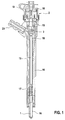
- a known fuel injection valve has a in a first housing part 16 (nozzle body) liftably guided injection valve member 1 in the form of a nozzle needle, to which a valve piston 15 is attached as an extension.
- the valve piston 15 is also guided in a liftable manner in a second housing part 16 (injector body) and received in a valve piece 18 at its end facing away from the nozzle needle.
- a control chamber 3 Inside the valve piece 18 is limited by the valve piston 15, a control chamber 3, in which in the closed position of a solenoid valve 2, a valve piston 15 and thus the injection valve member 1 in the closing direction acting hydraulic pressure prevails.
- the hydraulic pressure in the control chamber 3 that acts on the injection valve member 1 in the closing direction is ensured by an inlet throttle 21, which is in communication with a high-pressure port 20 for the supply of fuel under high pressure.
- the high pressure port 20 is further in communication with a high pressure bore 17 through which the high pressure fuel is supplied to at least one injection port of the fuel injection valve.
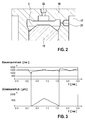
- the control chamber 3 a further throttle, namely an outlet throttle 22, via which a hydraulic connection of the control chamber 3 is made with a pressure chamber 24 of the solenoid valve 2 (see also Fig. 4 and 5 ).
- a further throttle namely an outlet throttle 22
- fuel can flow out of the control chamber 3 and the pressure chamber 24 of the solenoid valve 2 via the outlet throttle 22 and the valve seat 14 in the pressure chamber 24 of the solenoid valve 2.
- the result is a pressure drop in the control chamber 3, which has an opening stroke of the injection valve member 1 result.
- this is energized, so that cooperating with the valve seat 14 armature 13 of the solenoid valve 2 is lifted from its sealing seat and the valve seat 14 opens.
- an electrical connection 19 is provided on the fuel injection valve (see Fig. 1 ).
- control chamber pressure reaches its minimum immediately before the start of the opening stroke of the injection valve member.
- the spring element 4 is formed as a plate spring and supported on a serving as a support plate housing part 16.
- the anchor bolt 5 is surrounded by a magnetic core 11 in which a coil 7 is received.
- coupling means 6 are provided which mechanically connect the coil 7 with the spring element 4 in such a way that an elastic deformation of the spring element 4 causes a change in position of the coil 7 relative to the magnetic core 11.
- the coil 7 is axially displaceable for this purpose received in the magnetic core 11 and the magnetic core 11 via a clamping element 23 which biases the magnetic core 11 relative to a radial shoulder on the housing part 16, fixed in position.
- the change in position of the coil 7 leads to a parameter change, for example a change in the coil voltage or the coil current, in the existing magnetic circuit 9, so that the closing time of the injection valve member 1 can be reliably detected via the detection of the parameter change.
- FIG. 5 An alternative embodiment is from the Fig. 5 out.
- the spring element 4 is designed differently and the mechanical coupling of the spring element 4 with the coil 7 via the coupling means 6 in such a way that the change in position of the coil 7 takes place in the opposite direction to the movement of the anchor bolt 5. It can thus be effected a direction reversal.
- the path of the coil 7 differ from the path of the anchor bolt 5, so that further a path translation is realized.
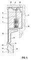
- FIG. 6 Another alternative embodiment is in Fig. 6 shown.
- a coupling means 6 a further magnetic circuit 10 with a further coil. 8 used.
- the housing-side support plate forms the spring element 4, which is therefore designed elastically deformable.
- the second coil 8 is received in the magnetic core 11 and between the magnetic core 11 and the spring element 4, an air gap 25 is formed, which changes in an elastic deformation of the spring element 4, in this case enlarged.
- This has the consequence that the inductance in the magnetic circuit 10 changes.
- There is a parameter change which in turn is detectable and allows a conclusion on the closing time of the injection valve member 1.
- the Fig. 7 shows a modification of the embodiment of the Fig. 6 , The difference is that the second coil 8 is integrated into the spring element 4. In the case of an elastic deformation of the spring element 4, a change in the position of the coil 8 takes place, which likewise results in the air gap 25 being enlarged.
- the respective second coil 8 is connected in parallel or in series with the coil 7 of the primary circuit.
- the parallel connection is exemplary for the embodiment of the Fig. 7 in Fig. 8 shown.
- Fig. 9 shows the corresponding series connection. While in parallel connection, the inductance of the second coil 8 must be selected to be high in comparison to the first coil 7 in order not to impair the function of the primary circuit, it is the other way round in the series connection. That is, in the series connection, the number of turns of the second coil 8 may be smaller than that of the first coil 7.
- the invention By detecting the closing time of the injection valve member, not only the dynamic behavior of the servo valve is taken into account in the determination of the injection duration, but all possible inaccuracies within the entire switching chain from the actuator to the nozzle needle or to the injection valve member.
- the invention is capable of compensating for example scattering of similar valves, as well as their drift over the life and the influence of variable influencing variables, such as the influence of pressure oscillations.
- the injected amount of fuel is therefore determinable and adjustable with higher accuracy.
Landscapes
- Engineering & Computer Science (AREA)
- Chemical & Material Sciences (AREA)
- Combustion & Propulsion (AREA)
- Mechanical Engineering (AREA)
- General Engineering & Computer Science (AREA)
- Physics & Mathematics (AREA)
- Analytical Chemistry (AREA)
- Fluid Mechanics (AREA)
- Electromagnetism (AREA)
- Fuel-Injection Apparatus (AREA)
Abstract
Description
- Die Erfindung betrifft ein Verfahren zur Erkennung des Schließzeitpunktes eines Einspritzventilgliedes in einem Kraftstoffeinspritzventil zum Einspritzen von Kraftstoff in den Brennraum einer Brennkraftmaschine sowie ein hierzu geeignetes Kraftstoffeinspritzventil.
- Der Schließzeitpunkt des Einspritzventilgliedes lässt Rückschlüsse auf die Einspritzdauer zu, wobei die Einspritzdauer und der Einspritzdruck die eingespritzte Kraftstoffmenge bestimmen. Darüber hinaus gibt es weitere Einflussgrößen, wie beispielsweise Fertigungstoleranzen, Verschleiß von Bauteilen und im System auftretende Druckwellen, die zu Ungenauigkeiten in Bezug auf die eingespritzte Kraftstoffmenge führen können. Diese Einflussgrößen gewinnen insbesondere dann an Bedeutung, wenn die Betätigung des Einspritzventilgliedes indirekt über ein aktorbetätigtes Servoventil erfolgt. Denn innerhalb der Schaltkette vom Aktor, über das Servoventil und die Hochdruckhydraulik bis hin zum Einspritzventilglied kommt es oftmals zu Abweichungen, die Einfluss auf die Öffnungsdauer des Einspritzventilgliedes und damit auf die Einspritzdauer haben. Einen mitbestimmenden Faktor stellt dabei auch das dynamische Verhalten des Servoventils dar.
- Aus dem Stand der Technik sind bereits verschiedene Verfahren und/oder Vorrichtungen zur Bestimmung der Öffnungsdauer eines Einspritzventilgliedes bekannt, um die Genauigkeit der eingespritzten Kraftstoffmenge zu optimieren.
- Aus der Offenlegungsschrift
DE 10 2007 031 552 A1 ist beispielsweise ein Verfahren zum Ermitteln der Position eines Ankers in einem Magnetventil sowie eine Vorrichtung zum Betreiben eines Magnetventils mit einem Anker bekannt. Da bei Kraftstoffinjektoren, die mittels eines Magnetventils betrieben werden, die Öffnungsdauer des Magnetventils einen entscheidenden Einfluss auf die eingespritzte Menge Kraftstoff hat, wird die Öffnungsdauer über die Ansteuerdauer einer Magnetspule des Magnetventils mittelbar eingestellt. Um die geeignete Ansteuerdauer zu ermitteln, müssen die Verzugszeit und die Schließzeit des Magnetventils unter den aktuellen Bedingungen bekannt sein. Während die Verzugszeit mit guter Genauigkeit vorhersagbar ist, hängt die Schließzeit von vielen Faktoren ab, die Schwankungen bewirken können, und ist daher nur unzureichend vorhersagbar. Die Schließzeit wird daher über die Position des Ankers des Magnetventils ermittelt. Über die Erkennung des Schließzeitpunktes des Magnetventils lassen sich jedoch keine Fehler und/oder Streuungen innerhalb der Hochdruckhydraulik erkennen. - Aus der Offenlegungsschrift
DE 10 2006 051 206 A1 ist des Weiteren ein Kraftstoffinjektor mit einer Messeinrichtung zur Erfassung des Endes eines Einspritzvorgangs bzw. der Erfassung des Anschlags eines Öffnungshubes einer Düsennadel bekannt. Die Messeinrichtung ist als Wirbelstromsensor mit einem Messkörper ausgeführt. Der Messkörper umgibt eine Bewegungseinrichtung, insbesondere eine Düsennadel, welche wenigstens im Bereich ihrer Umschließung durch den Messkörper eine Magnetisierung aufweist. Die Messeinrichtung wird mit konstantem Gleichstrom oder mit einer konstanten Gleichspannung betrieben, wobei eine Abweichung von der Gleichspannung bzw. vom Gleichstrom als Messsignal dient. Insbesondere ergibt sich aus der Änderung der periodischen Düsennadelbewegung eine Änderung des mittels der Messeinrichtung ausgegebenen Messsignals in Form einer Unstetigkeit. Mittels dieser Unstetigkeit werden die Hubanschlags- oder Schließzeitpunkte periodisch aufeinander folgender Öffnungs- oder Schließzyklen ermittelt. Die vorgesehene Messeinrichtung stellt jedoch ein zusätzliches Bauteil dar, das es in einen Gehäuseteil des Injektors zu integrieren gilt. Zudem sind separate elektrische Anschlüsse für die Messeinrichtung erforderlich. Der konstruktive Aufwand ist dementsprechend hoch. - Der Erfindung liegt die Aufgabe zugrunde, ein einfaches Verfahren und einen einfach aufgebauten Kraftstoffinjektor bereit zu stellen, welche die Erkennung des Schließzeitpunktes der Düsennadel und demzufolge eine hohe Genauigkeit in der Bestimmung der Einspritzmenge ermöglichen.
- Die Aufgabe wird gelöst von einem Verfahren gemäß Anspruch 1 und von einem Kraftstoffeinspritzventil gemäß Anspruch 7. Vorteilhafte Weiterbildungen der Erfindung sind in den jeweiligen Unteransprüchen angegeben.
- Bei dem vorgeschlagenen Verfahren zur Erkennung des Schließzeitpunktes eines Einspritzventilgliedes in einem Kraftstoffeinspritzventil wird das Einspritzventilglied über ein Magnetventil angesteuert, indem durch Öffnen oder Schließen des Magnetventils ein das Einspritzventilglied in Schließrichtung beaufschlagender hydraulischer Druck in einem Steuerraum verändert wird. Das Magnetventil umfasst dabei einen axial verschiebbar gelagerten und an einem Federelement abgestützten Ankerbolzen, der von einer Axialkraft beaufschlagt wird, die proportional zum hydraulischen Druck im Steuerraum ist. Erfindungsgemäß werden Kopplungsmittel eingesetzt, über welche das Federelement und eine Spule wenigstens eines Magnetkreises gekoppelt sind und über welche bei einer elastischen Verformung des Federelementes eine detektierbare Parameteränderung, vorzugsweise eine Änderung der Spulenspannung oder des Spulenstroms, in zumindest einem Magnetkreis bewirkt werden. Die elastische Verformung des Federelementes wird wiederum über eine axiale Verschiebung des an dem Federelement abgestützten Ankerbolzens bewirkt, die dann erfolgt, wenn der hydraulische Druck im Steuerraum und damit die auf den Ankerbolzen wirkende Axialkraft ansteigen. Dies ist unmittelbar nach dem Schließzeitpunkt des Einspritzventilgliedes der Fall, so dass der Schließzeitpunkt anhand der Parameteränderung im Magnetkreis ermittelt bzw. erkannt werden kann.
- Zur Erkennung des Schließzeitpunktes des Einspritzventilgliedes bedarf es vorliegend keiner separaten Messeinrichtung, da der Magnetkreis eines zur Betätigung des Kraftstoffeinspritzventils vorgesehenen Magnetaktors herangezogen werden kann. Zusätzliche elektrische Anschlüsse sind ebenfalls nicht erforderlich. Das zur Durchführung des vorgeschlagenen Verfahrens eingesetzte Kraftstoffeinspritzventil kann demnach einfach aufgebaut sein.
- Bevorzugt wird die Parameteränderung im Magnetkreis über eine Positionsänderung der Spule gegenüber einem Magnetkern, vorzugsweise dem Magnetkern des Magnetaktors, bewirkt. Bevorzugt werden hierzu das Federelement und die Spule des Magnetkreises über die Kopplungsmittel mechanisch gekoppelt. Bei einer elastischen Verformung des Federelementes wird dann durch eine Positionsänderung der Spule gegenüber dem Magnetkern eine detektierbare Parameteränderung im Magnetkreis bewirkt wird. Die Parameteränderung betrifft vorzugsweise eine Änderung der Spulenspannung oder des Spulenstromes.
- Weiterhin bevorzugt werden über die Kopplungsmittel eine Richtungsumkehr und/oder eine Wegübersetzung bewirkt. Die Positionsänderung der Spule kann demnach in eine der Ankerbolzenbewegung entgegen gesetzte Richtung erfolgen und/oder die Spule kann einen größeren oder kleineren Weg als der Ankerbolzen zurücklegen.
- Gemäß einem alternativen Verfahren werden das Federelement und die Spule des Magnetkreises über einen als Kopplungsmittel dienenden zweiten Magnetkreis mit einer zweiten Spule gekoppelt. Bei einer elastischen Verformung des Federelementes wird dann eine detektierbare Parameteränderung zumindest im zweiten Magnetkreis bewirkt. Die Kopplung über den zweiten Magnetkreis ersetzt eine mechanische Kopplung. Die zweite Spule kann dabei in das Federelement eingesetzt sein, so dass bei einer elastischen Verformung des Federelementes auch eine Positionsänderung der zweiten Spule und damit eine Parameteränderung im zweiten Magnetkreis erfolgt. Alternativ ist die zweite Spule derart angeordnet, dass zwischen Spule und Federelement ein Luftspalt besteht. Bei einer elastischen Verformung des Federelementes verändert sich dieser Luftspalt und somit die Induktivität dieses Magnetkreises. Der zweite Magnetkreis wird vorzugsweise aus dem Federelement, dem Magnetkern des Magnetaktors und der zweiten Spule gebildet, wobei die Spule Bestandteil des Federelementes oder des Magnetkerns sein kann. Als Bestandteil des Federelementes kann die Spule beispielsweise als gedruckte Flachspule ausgeführt sein; die auf das Federelement aufgeklebt wird.
- Vorzugsweise wird die zweite Spule des zweiten Magnetkreises parallel oder in Reihe mit der ersten Spule des ersten Magnetkreises geschaltet. Auf diese Weise sind keine weiteren elektrischen Anschlüsse erforderlich. Einer weiteren Leitung zu einem Steuergerät bedarf es ebenfalls nicht. Die Anschlüsse des Kraftstoffeinspritzventils bleiben demnach unverändert.
- Es gilt jedoch zu beachten, dass bei einer parallelen Schaltung die zweite Spule eine sehr hohe Induktivität im Vergleich zur ersten Spule aufweisen muss, damit die Funktion des ersten Magnetkreises sichergestellt ist. Das heißt, dass die Windungszahl der zweiten Spule im Vergleich zur ersten Spule groß ist. Bei einer Reihenschaltung verhält es sich umgekehrt. Das heißt, dass die zweite Spule eine geringe Induktivität und eine geringe Windungszahl im Vergleich zur ersten Spule aufweist.
- Die Parameteränderung in einem Magnetkreis wird bei Vorhandensein eines Restflusses ermittelt. Alternativ oder ergänzend wird durch erneute Bestromung des Magnetventils vor dem erwarteten Schließzeitpunkt des Einspritzventilgliedes ein zur Ermittlung der Parameteränderung ausreichender Magnetfluss aufgebaut. Die Bestromung ist dabei derart zu gestalten, dass das Magnetventil nicht erneut öffnet.
- Ferner wird ein Kraftstoffeinspritzventil zum Einspritzen von Kraftstoff in den Brennraum einer Brennkraftmaschine mit einem Magnetventil zum Ansteuern eines Einspritzventilgliedes vorgeschlagen, wobei durch Öffnen oder Schließen des Magnetventils ein das Einspritzventilglied in Schließrichtung beaufschlagender hydraulischer Druck in einem Steuerraum verändert wird. Das Magnetventil des vorgeschlagenen Kraftstoffeinspritzventils umfasst einen axial verschiebbar gelagerten und an einem Federelement abgestützten Ankerbolzen, der von einer Axialkraft beaufschlagbar ist, die proportional zum hydraulischen Druck im Steuerraum ist. Erfindungsgemäß sind Kupplungsmittel vorgesehen, über welche das Federelement und eine Spule wenigstens eines Magnetkreises gekoppelt sind und welche bei einer elastischen Verformung des Federelementes eine detektierbare Parameteränderung, vorzugsweise eine Änderung der Spulenspannung oder des Spulenstroms, in zumindest einem Magnetkreis bewirken.
- Wesentliches Merkmal des erfindungsgemäßen Kraftstoffeinspritzventils sind demnach die Kopplungsmittel, welche die Durchführung des vorstehend beschriebenen erfindungsgemäßen Verfahrens ermöglichen. Bei dem Magnetventil handelt es sich zudem bevorzugt um ein druckausgeglichenes Magnetventil, wobei der Druckausgleich über den Ankerbolzen erfolgt, der in einer Führungsbohrung des Ankers geführt. Dabei ist der Führungsdurchmesser des Ankers und der Sitzdurchmesser des Magnetventils näherungsweise gleich gewählt. Dadurch wirkt die hydraulische Kraft über die von der Sitzlinie des Ventils umschlossene Fläche nicht als Öffnungskraft auf den beweglichen Anker, sondern auf den am Federelement abgestützten Ankerbolzen. Das Federelement kann beispielsweise auch eine elastisch verformbare Abstützplatte sein.
- Da das vorgeschlagene Kraftstoffeinspritzventil die Durchführung eines der vorstehend beschriebenen erfindungsgemäßen Verfahren ermöglicht, gelten die im Zusammenhang mit den Verfahren beschriebenen Vorteile auch für das Kraftstoffeinspritzventil. Darüber hinaus ist das vorgeschlagene Kraftstoffeinspritzventil einfach aufgebaut und kostengünstig herstellbar.
- Gemäß einer ersten bevorzugten Ausführungsform sind das Federelement und die Spule des Magnetkreises über die Kopplungsmittel mechanisch gekoppelt. Eine elastische Verformung des Federelementes bewirkt zudem eine Positionsänderung der Spule gegenüber einem Magnetkern und demzufolge eine detektierbare Parameteränderung im Magnetkreis. Eine mechanische Kopplung ist einfach herzustellen, beispielsweise über stangenförmige Kopplungselemente, das einerseits mit der Spule und andererseits mit dem Federelement verbunden sind. Darüber hinaus besteht eine Vielzahl an weiteren Kopplungsmöglichkeiten.
- Die Kopplungsmittel können beispielsweise derart ausgebildet sein, dass sie eine Richtungsumkehr und/oder eine Wegübersetzung bewirken. Die Positionsänderung der Spule kann demnach der Bewegungsrichtung des Ankerbolzens entgegen gesetzt sein und/oder der Weg der Spule kann größer oder kleiner als der Weg des Ankerbolzens sein. Wesentlich ist, dass die Spule derart angeordnet ist, dass sie ihre Position auch ändern kann. Vorzugsweise ist die Spule daher zumindest axial verschiebbar gelagert.
- Gemäß einer bevorzugten weiteren Ausführungsform ist als Kopplungsmittel ein zweiter Magnetkreis mit einer zweiten Spule vorgesehen und eine elastische Verformung des Federelementes bewirkt eine detektierbare Parameteränderung zumindest im zweiten Magnetkreis. Die Spule des zweiten Magnetkreises kann hierzu im bzw. am Federelement, beispielsweise als gedruckte und mittels Kleben befestigte Flachspule, oder im bzw. am Magnetkern des Primärkreises angeordnet sein. Hierbei wird - in Abhängigkeit von der gewählten Anordnung - ein Luftspalt zwischen der Spule und dem Magnetkern oder der Spule und dem Federelement ausgebildet, der sich bei einer elastischen Verformung des Federelementes verändert und somit zu einer Änderung der Induktivität des Magnetkreises führt.
- Bevorzugt sind die zweite Spule des zweiten Magnetkreises und die erste Spule des ersten Magnetkreises parallel oder in Reihe geschaltet. Diese Maßnahmen machen die Anordnung weiterer elektrischer Leitungen außerhalb des Kraftstoffeinspritzventils entbehrlich.
- Vorteilhafterweise ist das Magnetventil eines erfindungsgemäßen Kraftstoffeinspritzventils im Wesentlichen durckausgeglichen. Hierzu ist der Ankerbolzen des Magnetventils in einer Führungsbohrung eines Ankers aufgenommen, wobei der Durchmesser der Führungsbohrung und der Durchmesser eines mit dem Anker zusammenwirkenden Ventilsitzes näherungsweise gleich sind. Dadurch wirkt die hydraulische Kraft über die von der Sitzlinie des Ventils umschlossene Fläche nicht als Öffnungskraft auf den beweglichen Anker, sondern auf den am Federelement abgestützten Ankerbolzen. Das Federelement kann hierzu als elastisch verformbare Abstützplatte ausgebildet sein. Um die Elastizität der Abstützplatte zu erhöhen, können in dieser Aussparungen vorgesehen sein. Diese sind derart zu gestalten, dass der Magnetfluss im zweiten Magnetkreis nicht beeinträchtigt wird.
- Die erfindungsgemäße Verfahren nutzt die Tatsache, dass das Magnetventil während der Schließphase des Kraftstoffeinspritzventils geschlossen ist und in der Druckkammer des Magnetventils der Steuerraumdruck herrscht. Dieser Steuerraumdruck - und folglich die auf den Ankerbolzen wirkende Axialkraft - weisen im Schließzeitpunkt des Einspritzventils ein deutliches Minimum auf. Unmittelbar nach dem Schließen des Einspritzventilgliedes kommt es zu einem schnellen Anstieg des Steuerraumdrucks, der ferner einen Anstieg der auf den Ankerbolzen wirkenden Axialkraft bewirkt. Diese Kraftänderung führt bei einem erfindungsgemäßen Kraftstoffinjektor zu einer elastischen Verformung des Federelementes, wobei die vorgesehenen Kopplungsmittel die elastische Verformung des Federelementes in eine Positionsänderung einer Spule eines Magnetkreises und/oder in eine Größenveränderung eines Luftspaltes übersetzen, was wiederum eine Parameteränderung in dem die Spule und/oder den Luftspalt aufweisenden Magnetkreis zur Folge hat. Anhand dieser Parameteränderung kann dann der Schließzeitpunkt des Einspritzventilgliedes bestimmt werden.
- Bevorzugte Ausführungsformen der Erfindung werden nachfolgend anhand der Zeichnungen näher beschrieben. Diese zeigen:
-
Fig. 1 einen Längsschnitt durch ein Kraftstoffeinspritzventil gemäß dem Stand der Technik, -
Fig. 2 einen Detailausschnitt ausFig. 1 im Bereich des Steuerraums, -
Fig. 3 ein Diagramm zur Darstellung des zeitlichen Verlaufs und der Zusammenhänge des Hubes des Einspritzventilgliedes und des Steuerraumdrucks, -
Fig. 4 einen Längsschnitt durch ein erstes erfindungsgemäßes Kraftstoffeinspritzventil im Bereich des Magnetventils, -
Fig. 5 einen Längsschnitt durch ein zweites erfindungsgemäßes Kraftstoffeinspritzventil im Bereich des Magnetventils, -
Fig. 6 einen Längsschnitt durch ein Magnetventil eines dritten erfindungsgemäßen Kraftstoffeinspritzventils, -
Fig. 7 einen Längsschnitt durch ein Magnetventil eines vierten erfindungsgemäßen Kraftstoffeinspritzventils und -
Fig. 8 und 9 jeweils ein Schaltschema eines Magnetventils gemäß derFig. 7 . - Das in der
Fig. 1 dargestellte bekannte Kraftstoffeinspritzventil weist ein in einem ersten Gehäuseteil 16 (Düsenkörper) hubbeweglich geführtes Einspritzventilglied 1 in Form einer Düsennadel auf, an welche ein Ventilkolben 15 als Verlängerung angesetzt ist. Der Ventilkolben 15 ist in einem zweiten Gehäuseteil 16 (Injektorkörper) ebenfalls hubbeweglich geführt und an seinem der Düsennadel abgewandtem Ende in einem Ventilstück 18 aufgenommen. Innerhalb des Ventilstücks 18 wird durch den Ventilkolben 15 ein Steuerraum 3 begrenzt, in welchem in Schließstellung eines Magnetventils 2 ein den Ventilkolben 15 und damit das Einspritzventilglied 1 in Schließrichtung beaufschlagender hydraulischer Druck herrscht. Der das Einspritzventilglied 1 in Schließrichtung beaufschlagende hydraulische Druck im Steuerraum 3 wird durch eine Zulaufdrossel 21 sichergestellt, welche in Verbindung mit einem Hochdruck-Anschluss 20 für die Zuleitung von unter hohem Druck stehenden Kraftstoff steht. Der Hochdruck-Anschluss 20 steht ferner in Verbindung mit einer Hochdruckbohrung 17, über welche der unter hohem Druck stehende Kraftstoff wenigstens einer Einspritzöffnung des Kraftstoffeinspritzventils zugeführt wird. - Wie aus
Fig. 2 ersichtlich weist der Steuerraum 3 eine weitere Drossel, nämlich eine Ablaufdrossel 22 auf, über welche eine hydraulische Verbindung des Steuerraums 3 mit einer Druckkammer 24 des Magnetventils 2 hergestellt wird (siehe auchFig. 4 und5 ). In der Druckkammer 24 des Magnetventils 2 herrscht somit bei geschlossenem Magnetventil 2 der hydraulische Druck des Steuerraums 3. Wird nun das Magnetventil 2 geöffnet, kann über die Ablaufdrossel 22 und den Ventilsitz 14 Kraftstoff aus dem Steuerraum 3 und der Druckkammer 24 des Magnetventils 2 abströmen. Die Folge ist ein Druckabfall im Steuerraum 3, der einen Öffnungshub des Einspritzventilgliedes 1 zur Folge hat. Zum Öffnen des Magnetventils 2 wird dieses bestromt, so dass ein mit dem Ventilsitz 14 zusammenwirkender Anker 13 des Magnetventils 2 aus seinem Dichtsitz gehoben wird und den Ventilsitz 14 öffnet. Zur Bestromung des Magnetventils 2 ist am Kraftstoffeinspritzventil ein elektrischer Anschluss 19 vorgesehen (sieheFig. 1 ). - Die Zusammenhänge zwischen dem Steuerraumdruck und dem Öffnungshub der Düsennadel bzw. des Einspritzventilgliedes 1 gehen aus dem Diagramm der
Fig. 3 hervor. Die Rückwirkung von Öffnen und Schließen des Einspritzventilgliedes 1 auf den Steuerraumdruck sind deutlich zu sehen. So erreicht der Steuerraumdruck sein Minimum unmittelbar vor Beginn des Öffnungshubes des Einspritzventilgliedes 1. - Diese Zusammenhänge kommen insbesondere zum Tragen, wenn ein druckausgeglichenes Magnetventil 2 zur Ansteuerung des Einspritzventilgliedes 1 Verwendung findet (siehe
Fig. 4 und5 ). Der Druckausgleich erfolgt über einen Ankerbolzen 5, der in einer Führungsbohrung 12 des Ankers 13 axial verschiebbar geführt ist, wobei der Durchmesser der Führungsbohrung 12 zumindest näherungsweise gleich dem Durchmesser des Ventilsitzes 14 gewählt ist. Dadurch wirkt keine hydraulische Kraft auf den Anker 13, sondern lediglich auf den Ankerbolzen 5, der an einem Federelement 4 abgestützt ist. Dabei wird der Ankerbolzen 5 von einer Axialkraft beaufschlagt, die proportional zum hydraulischen Druck im Steuerraum 3 ist. Die Axialkraft bewirkt, dass der Ankerbolzen 5 in Richtung des Federelementes 4 axial verschoben wird, wobei das Federelement 4 eine elastische Verformung erfährt. - Bei dem in der
Fig. 4 dargestellten ersten erfindungsgemäßen Kraftstoffeinspritzventil ist das Federelement 4 als Tellerfeder ausgebildet und an einem als Abstützplatte dienenden Gehäuseteil 16 abgestützt. Der Ankerbolzen 5 ist von einem Magnetkern 11 umgeben, in dem eine Spule 7 aufgenommen ist. Ferner sind Kopplungsmittel 6 vorgesehen, welche die Spule 7 mit dem Federelement 4 in der Weise mechanisch verbinden, dass eine elastische Verformung des Federelementes 4 eine Positionsänderung der Spule 7 gegenüber dem Magnetkern 11 bewirkt. Die Spule 7 ist hierzu axial verschiebbar im Magnetkern 11 aufgenommen und der Magnetkern 11 über ein Spannelement 23, das den Magnetkern 11 gegenüber einem radialen Absatz am Gehäuseteil 16 vorspannt, lagefixiert. Die Positionsänderung der Spule 7 führt zu einer Parameteränderung, beispielsweise einer Änderung der Spulenspannung oder des Spulenstroms, im vorhandenen Magnetkreis 9, so dass über die Detektion der Parameteränderung der Schließzeitpunkt des Einspritzventilgliedes 1 zuverlässig erkannt werden kann. - Eine alternative Ausführungsform geht aus der
Fig. 5 hervor. Diese unterscheidet sich von der derFig. 4 dadurch, dass das Federelement 4 unterschiedlich ausgebildet ist und die mechanische Kopplung des Federelementes 4 mit der Spule 7 über die Kopplungsmittel 6 in der Weise erfolgt, dass die Positionsänderung der Spule 7 in entgegengesetzter Richtung zur Bewegung des Ankerbolzens 5 erfolgt. Es kann somit eine Richtungsumkehr bewirkt werden. Zudem unterscheiden sich der Weg der Spule 7 vom Weg des Ankerbolzens 5, so dass ferner eine Wegübersetzung realisiert wird. - Eine weitere alternative Ausführungsform ist in der
Fig. 6 gezeigt. Hier werden als Kopplungsmittel 6 ein weiterer Magnetkreis 10 mit einer weiteren Spule 8 eingesetzt. Zudem bildet die gehäuseseitige Abstützplatte das Federelement 4 aus, welche demnach elastisch verformbar ausgeführt ist. Die zweite Spule 8 ist in dem Magnetkern 11 aufgenommen und zwischen dem Magnetkern 11 und dem Federelement 4 ist ein Luftspalt 25 ausgebildet, der sich bei einer elastischen Verformung des Federelementes 4 verändert, vorliegend vergrößert. Dies hat zur Folge, dass sich die Induktivität im Magnetkreis 10 ändert. Es erfolgt eine Parameteränderung, die wiederum detektierbar ist und einen Rückschluss auf den Schließzeitpunkt des Einspritzventilgliedes 1 zulässt. - Die
Fig. 7 zeigt eine Abwandlung der Ausführungsform derFig. 6 . Der Unterschied besteht darin, dass die zweite Spule 8 in das Federelement 4 integriert ist. Bei einer elastischen Verformung des Federelementes 4 erfolgt demnach eine Positionsänderung der Spule 8, die ebenfalls dazu führt, dass der Luftspalt 25 eine Vergrößerung erfährt. - Um weitere elektrische Leitungen bzw. einen weiteren elektrischen Anschluss 19 zu vermeiden, ist die jeweils zweite Spule 8 parallel oder in Reihe mit der Spule 7 des Primärkreises geschaltet. Die Parallelschaltung ist beispielhaft für die Ausführungsform der
Fig. 7 inFig. 8 dargestellt.Fig. 9 zeigt die entsprechende Reihenschaltung. Während bei der Parallelschaltung die Induktivität der zweiten Spule 8 im Vergleich zur ersten Spule 7 hoch gewählt sein muss, um die Funktion des Primärkreises nicht zu beeinträchtigen, verhält es sich bei der Reihenschaltung anders herum. Das heißt, dass bei der Reihenschaltung die Windungszahl der zweiten Spule 8 geringer als die der ersten Spule 7 sein kann. - Allen dargestellten Ausführungsformen eines erfindungsgemäßen Kraftstoffeinspritzventils gemeinsam ist, dass das Magnetventil 2 jeweils derart ausgelegt und konstruiert ist, dass das Schließen des Einspritzventilgliedes 1 eine detektierbare Parameteränderung in einem Magnetkreis des Magnetventils 2 zur Folge hat. Über die Parameteränderung kann demnach in zuverlässiger Weise der Schließzeitpunkt des Einspritzventilgliedes 1 ermittelt werden.
- Zur Durchführung des Verfahrens ist es erforderlich, das ein ausreichender Restfluss im jeweiligen Magnetkreis vorhanden ist. Sofern dies nicht der Fall ist, wird vorgeschlagen, das Magnetventil 2 erneut kurz zu bestromen, um einen ausreichenden Magnetfluss zu gewährleisten. Dabei ist jedoch Sorge zu tragen, dass das Magnetventil 2 nicht erneut öffnet. Denn dies hätte einen Druckabfall im Steuerraum 3 und ggf. einen erneuten Öffnungshub des Einspritzventilgliedes 1 zur Folge.
- Indem der Schließzeitpunkt des Einspritzventilgliedes erfasst wird, findet bei der Ermittlung der Einspritzdauer nicht nur das dynamische Verhalten des Servoventils Berücksichtigung, sondern sämtliche etwaige Ungenauigkeiten innerhalb der gesamten Schaltkette vom Aktor bis zur Düsennadel bzw. bis zum Einspritzventilglied. Die Erfindung vermag sowohl Exemplarstreuungen gleichartiger Ventile auszugleichen, als auch deren Drift über die Lebensdauer sowie den Einfluss variabler Einflussgrößen, wie beispielsweise den Einfluss von Druckschwingungen. Die eingespritzte Kraftstoffmenge ist demnach mit höherer Genauigkeit bestimmbar und einstellbar.
Claims (12)
- Verfahren zur Erkennung des Schließzeitpunktes eines Einspritzventilgliedes (1) in einem Kraftstoffeinspritzventil zum Einspritzen von Kraftstoff in den Brennraum einer Brennkraftmaschine, wobei das Einspritzventilglied (1) über ein Magnetventil (2) angesteuert wird, indem durch Öffnen oder Schließen des Magnetventils(2) ein das Einspritzventilglied (1) in Schließrichtung beaufschlagender hydraulischer Druck in einem Steuerraum (3) verändert wird, und wobei das Magnetventil (2) einen axial verschiebbar gelagerten und an einem Federelement (4) abgestützten Ankerbolzen (5) umfasst, der von einer Axialkraft beaufschlagt wird, die proportional zum hydraulischen Druck im Steuerraum (3) ist,
dadurch gekennzeichnet, dass Kopplungsmittel (6) eingesetzt werden, über welche das Federelement (4) und eine Spule (7, 8) wenigstens eines Magnetkreises (9, 10) gekoppelt sind und über welche bei einer elastischen Verformung des Federelementes (4) eine detektierbare Parameteränderung, vorzugsweise eine Änderung der Spulenspannung oder des Spulenstroms, in zumindest einem Magnetkreis (9, 10) bewirkt werden. - Verfahren nach Anspruch 1,
dadurch gekennzeichnet, dass das Federelement (4) und die Spule (7) des Magnetkreises (9) über die Kopplungsmittel (6) mechanisch gekoppelt werden und bei einer elastischen Verformung des Federelementes (4) eine detektierbare Parameteränderung im Magnetkreis (9) durch eine Positionsänderung der Spule (7) gegenüber einem Magnetkern (11) bewirkt wird. - Verfahren nach Anspruch 1 oder 2,
dadurch gekennzeichnet, dass über die Kopplungsmittel (6) eine Richtungsumkehr und/oder eine Wegübersetzung bewirkt werden. - Verfahren nach Anspruch 1,
dadurch gekennzeichnet, dass das Federelement (4) und die Spule (7) des Magnetkreises (9) über einen als Kopplungsmittel (6) dienenden zweiten Magnetkreis (10) mit einer zweiten Spule (8) gekoppelt werden und bei einer elastischen Verformung des Federelementes (4) eine detektierbare Parameteränderung zumindest im zweiten Magnetkreis (10) bewirkt wird. - Verfahren nach Anspruch 4,
dadurch gekennzeichnet, dass die zweite Spule (8) des zweiten Magnetkreises (10) parallel oder in Reihe mit der ersten Spule (7) des ersten Magnetkreises (9) geschaltet wird. - Verfahren nach einem der vorhergehenden Ansprüche,
dadurch gekennzeichnet, dass die Parameteränderung in einem Magnetkreis (9, 10) bei Vorhandensein eines Restflusses ermittelt wird und/oder durch erneute Bestromung des Magnetventils (2) vor dem erwarteten Schließzeitpunkt des Einspritzventilgliedes (1) ein zur Ermittlung der Parameteränderung ausreichender Magnetfluss aufgebaut wird. - Kraftstoffeinspritzventil zum Einspritzen von Kraftstoff in den Brennraum einer Brennkraftmaschine mit einem Magnetventil (2) zum Ansteuern eines Einspritzventilgliedes (1), indem durch Öffnen oder Schließen des Magnetventils (2) ein das Einspritzventilglied (1) in Schließrichtung beaufschlagender hydraulischer Druck in einem Steuerraum (3) verändert wird und wobei das Magnetventil (2) einen axial verschiebbar gelagerten und an einem Federelement (4) abgestützten Ankerbolzen (5) umfasst, der von einer Axialkraft beaufschlagbar ist, die proportional zum hydraulischen Druck im Steuerraum (3) ist,
dadurch gekennzeichnet, dass Kupplungsmittel (6) vorgesehen sind, über welche das Federelement (4) und eine Spule (7, 8) wenigstens eines Magnetkreises (9, 10) gekoppelt sind und welche bei einer elastischen Verformung des Federelementes (4) eine detektierbare Parameteränderung, vorzugsweise eine Änderung der Spulenspannung oder des Spulenstroms, in zumindest einem Magnetkreis (9, 10) bewirken. - Kraftstoffeinspritzventil nach Anspruch 7,
dadurch gekennzeichnet, dass das Federelement (4) und die Spule (7) des Magnetkreises (9) über die Kopplungsmittel (6) mechanisch gekoppelt sind und eine elastische Verformung des Federelementes (4) eine Positionsänderung der Spule (7) gegenüber einem Magnetkern (11) und demzufolge eine detektierbare Parameteränderung im Magnetkreis (9) bewirkt. - Kraftstoffeinspritzventil nach Anspruch 7 oder 8,
dadurch gekennzeichnet, dass die Kopplungsmittel (6) eine Richtungsumkehr und/oder eine Wegübersetzung bewirken. - Kraftstoffeinspritzventil nach einem der Ansprüche 7 bis 9,
dadurch gekennzeichnet, dass ein zweiter Magnetkreis (10) mit einer zweiten Spule (8) als Kopplungsmittel (6) vorgesehen ist und eine elastische Verformung des Federelementes (4) eine detektierbare Parameteränderung zumindest im zweiten Magnetkreis (10) bewirkt. - Kraftstoffeinspritzventil nach Anspruch 10,
dadurch gekennzeichnet, dass die zweite Spule (8) des zweiten Magnetkreises (10) und die erste Spule (7) des ersten Magnetkreises (9) parallel oder in Reihe geschaltet sind. - Kraftstoffeinspritzventil nach einem der Ansprüche 7 bis 11,
dadurch gekennzeichnet, dass der Ankerbolzen des Magnetventils (2) in einer Führungsbohrung (12) eines Ankers (13) aufgenommen ist, wobei der Durchmesser der Führungsbohrung (12) und der Durchmesser eines mit dem Anker (13) zusammenwirkenden Ventilsitzes (14) näherungsweise gleich sind, so dass das Magnetventil (2) im Wesentlichen druckausgeglichen ist.
Applications Claiming Priority (1)
| Application Number | Priority Date | Filing Date | Title |
|---|---|---|---|
| DE102010001960A DE102010001960A1 (de) | 2010-02-16 | 2010-02-16 | Verfahren zur Erkennung des Schließzeitpunktes eines Einspritzventilgliedes in einem Kraftstoffeinspritzventil sowie Kraftstoffeinspritzventil |
Publications (3)
| Publication Number | Publication Date |
|---|---|
| EP2357353A2 true EP2357353A2 (de) | 2011-08-17 |
| EP2357353A3 EP2357353A3 (de) | 2015-08-26 |
| EP2357353B1 EP2357353B1 (de) | 2017-08-09 |
Family
ID=43927623
Family Applications (1)
| Application Number | Title | Priority Date | Filing Date |
|---|---|---|---|
| EP11150104.5A Active EP2357353B1 (de) | 2010-02-16 | 2011-01-04 | Verfahren zur Erkennung des Schließzeitpunktes eines Einspritzventilgliedes in einem Kraftstoffeinspritzventil sowie Kraftstoffeinspritzventil |
Country Status (2)
| Country | Link |
|---|---|
| EP (1) | EP2357353B1 (de) |
| DE (1) | DE102010001960A1 (de) |
Families Citing this family (1)
| Publication number | Priority date | Publication date | Assignee | Title |
|---|---|---|---|---|
| DE102014210605A1 (de) | 2013-09-17 | 2015-03-19 | Robert Bosch Gmbh | Kraftstoffinjektor |
Citations (2)
| Publication number | Priority date | Publication date | Assignee | Title |
|---|---|---|---|---|
| DE102006051206A1 (de) | 2006-10-30 | 2008-05-08 | Robert Bosch Gmbh | Kraftstoffinjektor mit einer Messeinrichtung |
| DE102007031552A1 (de) | 2007-07-06 | 2009-01-08 | Robert Bosch Gmbh | Verfahren zum Ermitteln einer Position eines Ankers in einem Magnetventil und Vorrichtung zum Betreiben eines Magnetventils mit einem Anker |
Family Cites Families (1)
| Publication number | Priority date | Publication date | Assignee | Title |
|---|---|---|---|---|
| DE102008001425A1 (de) * | 2008-04-28 | 2009-10-29 | Robert Bosch Gmbh | Kraftstoff-Einspritzvorrichtung |
-
2010
- 2010-02-16 DE DE102010001960A patent/DE102010001960A1/de not_active Withdrawn
-
2011
- 2011-01-04 EP EP11150104.5A patent/EP2357353B1/de active Active
Patent Citations (2)
| Publication number | Priority date | Publication date | Assignee | Title |
|---|---|---|---|---|
| DE102006051206A1 (de) | 2006-10-30 | 2008-05-08 | Robert Bosch Gmbh | Kraftstoffinjektor mit einer Messeinrichtung |
| DE102007031552A1 (de) | 2007-07-06 | 2009-01-08 | Robert Bosch Gmbh | Verfahren zum Ermitteln einer Position eines Ankers in einem Magnetventil und Vorrichtung zum Betreiben eines Magnetventils mit einem Anker |
Also Published As
| Publication number | Publication date |
|---|---|
| DE102010001960A1 (de) | 2011-08-18 |
| EP2357353A3 (de) | 2015-08-26 |
| EP2357353B1 (de) | 2017-08-09 |
Similar Documents
| Publication | Publication Date | Title |
|---|---|---|
| EP2478200B1 (de) | Verfahren und vorrichtung zum bestimmen einer bewegung eines nadels eines einspritzventils | |
| EP3114346B1 (de) | Verfahren zur regelung eines common-rail-injektors | |
| DE102010000827A1 (de) | Kraftstoffinjektor | |
| DE102015208573B3 (de) | Druckbestimmung in einem Kraftstoff-Einspritzventil | |
| EP1925814A1 (de) | Kraftstoffinjektor mit einer Messeinrichtung | |
| DE102014220795A1 (de) | Verfahren zur Vorgabe eines Stroms in einem Magnetventil | |
| DE102012206586A1 (de) | Verfahren zum Betreiben eines Kraftstoffinjektors | |
| EP2726723B1 (de) | Kraftstoffeinspritzventil | |
| EP2357353B1 (de) | Verfahren zur Erkennung des Schließzeitpunktes eines Einspritzventilgliedes in einem Kraftstoffeinspritzventil sowie Kraftstoffeinspritzventil | |
| DE102011086151A1 (de) | Verfahren zum Betreiben mindestens eines Magnetventils | |
| DE102017216942A1 (de) | Verfahren zum Kalibrieren eines Kraft- oder Drucksensors | |
| EP2392815B1 (de) | Magnetbaugruppe sowie Einspritzventil mit einer Magnetbaugruppe | |
| EP2496824B1 (de) | Steuerventilanordnung | |
| DE102014210561A1 (de) | Verfahren zur Steuerung von Mehrfacheinspritzungen insbesondere bei einem Kraftstoff-Einspritzsystem einer Brennkraftmaschine | |
| EP1925813B1 (de) | Kraftstoffinjektor mit einer Messeinrichtung | |
| DE102015217776A1 (de) | Verfahren zur Erkennung einer Schädigung einer Düsennadel eines Kraftstoffinjektors oder des Düsennadelsitzes | |
| EP2990639B1 (de) | Kraftstoffinjektor | |
| DE102018208712A1 (de) | Verfahren zur Korrektur eines ermittelten Einspritzbeginns | |
| DE102018210612A1 (de) | Verfahren zur Ermittlung eines Zeitpunkts eines Einspritzbeginns | |
| EP2426348A1 (de) | Brennstoffeinspritzventil | |
| DE102013207162B4 (de) | Verfahren und Datenverarbeitungseinrichtung zum Reduzieren eines Einschaltstroms für ein Ventil einer Hochdruckpumpe | |
| DE102016221062A1 (de) | Verfahren zum Betreiben eines Magnetventils | |
| DE10202324A1 (de) | Magnetventil und Verfahren zu seiner Herstellung | |
| DE102017205695A1 (de) | Verfahren zum Ermitteln eines Ankerhubes eines Kraftstoffinjektors | |
| DE102009044965A1 (de) | Verfahren zum Kontrollieren des Betriebs einer Enspritzdüse |
Legal Events
| Date | Code | Title | Description |
|---|---|---|---|
| PUAI | Public reference made under article 153(3) epc to a published international application that has entered the european phase |
Free format text: ORIGINAL CODE: 0009012 |
|
| AK | Designated contracting states |
Kind code of ref document: A2 Designated state(s): AL AT BE BG CH CY CZ DE DK EE ES FI FR GB GR HR HU IE IS IT LI LT LU LV MC MK MT NL NO PL PT RO RS SE SI SK SM TR |
|
| AX | Request for extension of the european patent |
Extension state: BA ME |
|
| PUAL | Search report despatched |
Free format text: ORIGINAL CODE: 0009013 |
|
| AK | Designated contracting states |
Kind code of ref document: A3 Designated state(s): AL AT BE BG CH CY CZ DE DK EE ES FI FR GB GR HR HU IE IS IT LI LT LU LV MC MK MT NL NO PL PT RO RS SE SI SK SM TR |
|
| AX | Request for extension of the european patent |
Extension state: BA ME |
|
| RIC1 | Information provided on ipc code assigned before grant |
Ipc: F02M 57/00 20060101ALI20150720BHEP Ipc: F02M 51/00 20060101AFI20150720BHEP Ipc: F02M 63/00 20060101ALI20150720BHEP Ipc: F02M 65/00 20060101ALI20150720BHEP Ipc: F02M 47/02 20060101ALI20150720BHEP Ipc: F02D 41/20 20060101ALI20150720BHEP |
|
| 17P | Request for examination filed |
Effective date: 20160226 |
|
| RBV | Designated contracting states (corrected) |
Designated state(s): AL AT BE BG CH CY CZ DE DK EE ES FI FR GB GR HR HU IE IS IT LI LT LU LV MC MK MT NL NO PL PT RO RS SE SI SK SM TR |
|
| GRAP | Despatch of communication of intention to grant a patent |
Free format text: ORIGINAL CODE: EPIDOSNIGR1 |
|
| RIC1 | Information provided on ipc code assigned before grant |
Ipc: F02M 63/00 20060101ALI20170324BHEP Ipc: F02M 47/02 20060101ALI20170324BHEP Ipc: F02D 41/20 20060101ALI20170324BHEP Ipc: F02M 65/00 20060101ALI20170324BHEP Ipc: F02M 57/00 20060101ALI20170324BHEP Ipc: F02M 51/00 20060101AFI20170324BHEP |
|
| INTG | Intention to grant announced |
Effective date: 20170428 |
|
| GRAS | Grant fee paid |
Free format text: ORIGINAL CODE: EPIDOSNIGR3 |
|
| GRAA | (expected) grant |
Free format text: ORIGINAL CODE: 0009210 |
|
| AK | Designated contracting states |
Kind code of ref document: B1 Designated state(s): AL AT BE BG CH CY CZ DE DK EE ES FI FR GB GR HR HU IE IS IT LI LT LU LV MC MK MT NL NO PL PT RO RS SE SI SK SM TR |
|
| REG | Reference to a national code |
Ref country code: GB Ref legal event code: FG4D Free format text: NOT ENGLISH |
|
| REG | Reference to a national code |
Ref country code: CH Ref legal event code: EP Ref country code: AT Ref legal event code: REF Ref document number: 917144 Country of ref document: AT Kind code of ref document: T Effective date: 20170815 |
|
| REG | Reference to a national code |
Ref country code: IE Ref legal event code: FG4D Free format text: LANGUAGE OF EP DOCUMENT: GERMAN |
|
| REG | Reference to a national code |
Ref country code: DE Ref legal event code: R096 Ref document number: 502011012754 Country of ref document: DE |
|
| REG | Reference to a national code |
Ref country code: NL Ref legal event code: MP Effective date: 20170809 |
|
| REG | Reference to a national code |
Ref country code: LT Ref legal event code: MG4D |
|
| REG | Reference to a national code |
Ref country code: FR Ref legal event code: PLFP Year of fee payment: 8 |
|
| PG25 | Lapsed in a contracting state [announced via postgrant information from national office to epo] |
Ref country code: NL Free format text: LAPSE BECAUSE OF FAILURE TO SUBMIT A TRANSLATION OF THE DESCRIPTION OR TO PAY THE FEE WITHIN THE PRESCRIBED TIME-LIMIT Effective date: 20170809 Ref country code: HR Free format text: LAPSE BECAUSE OF FAILURE TO SUBMIT A TRANSLATION OF THE DESCRIPTION OR TO PAY THE FEE WITHIN THE PRESCRIBED TIME-LIMIT Effective date: 20170809 Ref country code: LT Free format text: LAPSE BECAUSE OF FAILURE TO SUBMIT A TRANSLATION OF THE DESCRIPTION OR TO PAY THE FEE WITHIN THE PRESCRIBED TIME-LIMIT Effective date: 20170809 Ref country code: FI Free format text: LAPSE BECAUSE OF FAILURE TO SUBMIT A TRANSLATION OF THE DESCRIPTION OR TO PAY THE FEE WITHIN THE PRESCRIBED TIME-LIMIT Effective date: 20170809 Ref country code: NO Free format text: LAPSE BECAUSE OF FAILURE TO SUBMIT A TRANSLATION OF THE DESCRIPTION OR TO PAY THE FEE WITHIN THE PRESCRIBED TIME-LIMIT Effective date: 20171109 Ref country code: SE Free format text: LAPSE BECAUSE OF FAILURE TO SUBMIT A TRANSLATION OF THE DESCRIPTION OR TO PAY THE FEE WITHIN THE PRESCRIBED TIME-LIMIT Effective date: 20170809 |
|
| PG25 | Lapsed in a contracting state [announced via postgrant information from national office to epo] |
Ref country code: IS Free format text: LAPSE BECAUSE OF FAILURE TO SUBMIT A TRANSLATION OF THE DESCRIPTION OR TO PAY THE FEE WITHIN THE PRESCRIBED TIME-LIMIT Effective date: 20171209 Ref country code: RS Free format text: LAPSE BECAUSE OF FAILURE TO SUBMIT A TRANSLATION OF THE DESCRIPTION OR TO PAY THE FEE WITHIN THE PRESCRIBED TIME-LIMIT Effective date: 20170809 Ref country code: GR Free format text: LAPSE BECAUSE OF FAILURE TO SUBMIT A TRANSLATION OF THE DESCRIPTION OR TO PAY THE FEE WITHIN THE PRESCRIBED TIME-LIMIT Effective date: 20171110 Ref country code: BG Free format text: LAPSE BECAUSE OF FAILURE TO SUBMIT A TRANSLATION OF THE DESCRIPTION OR TO PAY THE FEE WITHIN THE PRESCRIBED TIME-LIMIT Effective date: 20171109 Ref country code: PL Free format text: LAPSE BECAUSE OF FAILURE TO SUBMIT A TRANSLATION OF THE DESCRIPTION OR TO PAY THE FEE WITHIN THE PRESCRIBED TIME-LIMIT Effective date: 20170809 Ref country code: LV Free format text: LAPSE BECAUSE OF FAILURE TO SUBMIT A TRANSLATION OF THE DESCRIPTION OR TO PAY THE FEE WITHIN THE PRESCRIBED TIME-LIMIT Effective date: 20170809 Ref country code: ES Free format text: LAPSE BECAUSE OF FAILURE TO SUBMIT A TRANSLATION OF THE DESCRIPTION OR TO PAY THE FEE WITHIN THE PRESCRIBED TIME-LIMIT Effective date: 20170809 |
|
| PG25 | Lapsed in a contracting state [announced via postgrant information from national office to epo] |
Ref country code: CZ Free format text: LAPSE BECAUSE OF FAILURE TO SUBMIT A TRANSLATION OF THE DESCRIPTION OR TO PAY THE FEE WITHIN THE PRESCRIBED TIME-LIMIT Effective date: 20170809 Ref country code: DK Free format text: LAPSE BECAUSE OF FAILURE TO SUBMIT A TRANSLATION OF THE DESCRIPTION OR TO PAY THE FEE WITHIN THE PRESCRIBED TIME-LIMIT Effective date: 20170809 Ref country code: RO Free format text: LAPSE BECAUSE OF FAILURE TO SUBMIT A TRANSLATION OF THE DESCRIPTION OR TO PAY THE FEE WITHIN THE PRESCRIBED TIME-LIMIT Effective date: 20170809 |
|
| REG | Reference to a national code |
Ref country code: DE Ref legal event code: R097 Ref document number: 502011012754 Country of ref document: DE |
|
| PG25 | Lapsed in a contracting state [announced via postgrant information from national office to epo] |
Ref country code: SK Free format text: LAPSE BECAUSE OF FAILURE TO SUBMIT A TRANSLATION OF THE DESCRIPTION OR TO PAY THE FEE WITHIN THE PRESCRIBED TIME-LIMIT Effective date: 20170809 Ref country code: EE Free format text: LAPSE BECAUSE OF FAILURE TO SUBMIT A TRANSLATION OF THE DESCRIPTION OR TO PAY THE FEE WITHIN THE PRESCRIBED TIME-LIMIT Effective date: 20170809 Ref country code: IT Free format text: LAPSE BECAUSE OF FAILURE TO SUBMIT A TRANSLATION OF THE DESCRIPTION OR TO PAY THE FEE WITHIN THE PRESCRIBED TIME-LIMIT Effective date: 20170809 Ref country code: SM Free format text: LAPSE BECAUSE OF FAILURE TO SUBMIT A TRANSLATION OF THE DESCRIPTION OR TO PAY THE FEE WITHIN THE PRESCRIBED TIME-LIMIT Effective date: 20170809 |
|
| PLBE | No opposition filed within time limit |
Free format text: ORIGINAL CODE: 0009261 |
|
| STAA | Information on the status of an ep patent application or granted ep patent |
Free format text: STATUS: NO OPPOSITION FILED WITHIN TIME LIMIT |
|
| 26N | No opposition filed |
Effective date: 20180511 |
|
| PG25 | Lapsed in a contracting state [announced via postgrant information from national office to epo] |
Ref country code: SI Free format text: LAPSE BECAUSE OF FAILURE TO SUBMIT A TRANSLATION OF THE DESCRIPTION OR TO PAY THE FEE WITHIN THE PRESCRIBED TIME-LIMIT Effective date: 20170809 |
|
| REG | Reference to a national code |
Ref country code: CH Ref legal event code: PL |
|
| GBPC | Gb: european patent ceased through non-payment of renewal fee |
Effective date: 20180104 |
|
| PG25 | Lapsed in a contracting state [announced via postgrant information from national office to epo] |
Ref country code: MT Free format text: LAPSE BECAUSE OF FAILURE TO SUBMIT A TRANSLATION OF THE DESCRIPTION OR TO PAY THE FEE WITHIN THE PRESCRIBED TIME-LIMIT Effective date: 20170809 |
|
| PG25 | Lapsed in a contracting state [announced via postgrant information from national office to epo] |
Ref country code: LU Free format text: LAPSE BECAUSE OF NON-PAYMENT OF DUE FEES Effective date: 20180104 |
|
| REG | Reference to a national code |
Ref country code: IE Ref legal event code: MM4A |
|
| REG | Reference to a national code |
Ref country code: BE Ref legal event code: MM Effective date: 20180131 |
|
| PG25 | Lapsed in a contracting state [announced via postgrant information from national office to epo] |
Ref country code: LI Free format text: LAPSE BECAUSE OF NON-PAYMENT OF DUE FEES Effective date: 20180131 Ref country code: CH Free format text: LAPSE BECAUSE OF NON-PAYMENT OF DUE FEES Effective date: 20180131 Ref country code: GB Free format text: LAPSE BECAUSE OF NON-PAYMENT OF DUE FEES Effective date: 20180104 Ref country code: BE Free format text: LAPSE BECAUSE OF NON-PAYMENT OF DUE FEES Effective date: 20180131 |
|
| PG25 | Lapsed in a contracting state [announced via postgrant information from national office to epo] |
Ref country code: IE Free format text: LAPSE BECAUSE OF NON-PAYMENT OF DUE FEES Effective date: 20180104 |
|
| REG | Reference to a national code |
Ref country code: AT Ref legal event code: MM01 Ref document number: 917144 Country of ref document: AT Kind code of ref document: T Effective date: 20180104 |
|
| PG25 | Lapsed in a contracting state [announced via postgrant information from national office to epo] |
Ref country code: AT Free format text: LAPSE BECAUSE OF NON-PAYMENT OF DUE FEES Effective date: 20180104 |
|
| PG25 | Lapsed in a contracting state [announced via postgrant information from national office to epo] |
Ref country code: MC Free format text: LAPSE BECAUSE OF FAILURE TO SUBMIT A TRANSLATION OF THE DESCRIPTION OR TO PAY THE FEE WITHIN THE PRESCRIBED TIME-LIMIT Effective date: 20170809 |
|
| PG25 | Lapsed in a contracting state [announced via postgrant information from national office to epo] |
Ref country code: TR Free format text: LAPSE BECAUSE OF FAILURE TO SUBMIT A TRANSLATION OF THE DESCRIPTION OR TO PAY THE FEE WITHIN THE PRESCRIBED TIME-LIMIT Effective date: 20170809 |
|
| PG25 | Lapsed in a contracting state [announced via postgrant information from national office to epo] |
Ref country code: HU Free format text: LAPSE BECAUSE OF FAILURE TO SUBMIT A TRANSLATION OF THE DESCRIPTION OR TO PAY THE FEE WITHIN THE PRESCRIBED TIME-LIMIT; INVALID AB INITIO Effective date: 20110104 Ref country code: PT Free format text: LAPSE BECAUSE OF FAILURE TO SUBMIT A TRANSLATION OF THE DESCRIPTION OR TO PAY THE FEE WITHIN THE PRESCRIBED TIME-LIMIT Effective date: 20170809 |
|
| PG25 | Lapsed in a contracting state [announced via postgrant information from national office to epo] |
Ref country code: MK Free format text: LAPSE BECAUSE OF NON-PAYMENT OF DUE FEES Effective date: 20170809 Ref country code: CY Free format text: LAPSE BECAUSE OF FAILURE TO SUBMIT A TRANSLATION OF THE DESCRIPTION OR TO PAY THE FEE WITHIN THE PRESCRIBED TIME-LIMIT Effective date: 20170809 |
|
| PG25 | Lapsed in a contracting state [announced via postgrant information from national office to epo] |
Ref country code: AL Free format text: LAPSE BECAUSE OF FAILURE TO SUBMIT A TRANSLATION OF THE DESCRIPTION OR TO PAY THE FEE WITHIN THE PRESCRIBED TIME-LIMIT Effective date: 20170809 |
|
| PGFP | Annual fee paid to national office [announced via postgrant information from national office to epo] |
Ref country code: FR Payment date: 20230123 Year of fee payment: 13 |
|
| PGFP | Annual fee paid to national office [announced via postgrant information from national office to epo] |
Ref country code: DE Payment date: 20240322 Year of fee payment: 14 |