EP2357322B1 - Mounting apparatus for low-ductility turbine shroud - Google Patents
Mounting apparatus for low-ductility turbine shroud Download PDFInfo
- Publication number
- EP2357322B1 EP2357322B1 EP11152436.9A EP11152436A EP2357322B1 EP 2357322 B1 EP2357322 B1 EP 2357322B1 EP 11152436 A EP11152436 A EP 11152436A EP 2357322 B1 EP2357322 B1 EP 2357322B1
- Authority
- EP
- European Patent Office
- Prior art keywords
- shroud
- support member
- turbine
- spring
- turbine shroud
- Prior art date
- Legal status (The legal status is an assumption and is not a legal conclusion. Google has not performed a legal analysis and makes no representation as to the accuracy of the status listed.)
- Active
Links
- 239000000463 material Substances 0.000 claims description 22
- 239000011153 ceramic matrix composite Substances 0.000 claims description 20
- 230000003068 static effect Effects 0.000 claims description 11
- 230000008901 benefit Effects 0.000 description 2
- 239000000919 ceramic Substances 0.000 description 2
- 238000001816 cooling Methods 0.000 description 2
- 239000000835 fiber Substances 0.000 description 2
- 230000033001 locomotion Effects 0.000 description 2
- 239000002184 metal Substances 0.000 description 2
- 229910052751 metal Inorganic materials 0.000 description 2
- 229910001092 metal group alloy Inorganic materials 0.000 description 2
- PZNSFCLAULLKQX-UHFFFAOYSA-N Boron nitride Chemical compound N#B PZNSFCLAULLKQX-UHFFFAOYSA-N 0.000 description 1
- 238000005452 bending Methods 0.000 description 1
- 238000005219 brazing Methods 0.000 description 1
- 230000006835 compression Effects 0.000 description 1
- 238000007906 compression Methods 0.000 description 1
- 239000000446 fuel Substances 0.000 description 1
- 239000011159 matrix material Substances 0.000 description 1
- 239000007769 metal material Substances 0.000 description 1
- 150000002739 metals Chemical class 0.000 description 1
- 238000012986 modification Methods 0.000 description 1
- 230000004048 modification Effects 0.000 description 1
- 230000000717 retained effect Effects 0.000 description 1
- 238000003466 welding Methods 0.000 description 1
Images


Classifications
-
- F—MECHANICAL ENGINEERING; LIGHTING; HEATING; WEAPONS; BLASTING
- F01—MACHINES OR ENGINES IN GENERAL; ENGINE PLANTS IN GENERAL; STEAM ENGINES
- F01D—NON-POSITIVE DISPLACEMENT MACHINES OR ENGINES, e.g. STEAM TURBINES
- F01D25/00—Component parts, details, or accessories, not provided for in, or of interest apart from, other groups
- F01D25/24—Casings; Casing parts, e.g. diaphragms, casing fastenings
- F01D25/246—Fastening of diaphragms or stator-rings
-
- F—MECHANICAL ENGINEERING; LIGHTING; HEATING; WEAPONS; BLASTING
- F01—MACHINES OR ENGINES IN GENERAL; ENGINE PLANTS IN GENERAL; STEAM ENGINES
- F01D—NON-POSITIVE DISPLACEMENT MACHINES OR ENGINES, e.g. STEAM TURBINES
- F01D11/00—Preventing or minimising internal leakage of working-fluid, e.g. between stages
- F01D11/08—Preventing or minimising internal leakage of working-fluid, e.g. between stages for sealing space between rotor blade tips and stator
- F01D11/12—Preventing or minimising internal leakage of working-fluid, e.g. between stages for sealing space between rotor blade tips and stator using a rubstrip, e.g. erodible. deformable or resiliently-biased part
Definitions
- This invention relates generally to gas turbine apparatus.
- a typical gas turbine engine includes a turbomachinery core having a high pressure compressor, a combustor, and a high pressure turbine in serial flow relationship.
- the core is operable in a known manner to generate a primary gas flow.
- the high pressure turbine also referred to as a gas generator turbine
- Each rotor comprises an annular array of blades or buckets carried by a rotating disk.
- the flowpath through the rotor is defined in part by a shroud, which is a stationary structure which circumscribes the tips of the blades or buckets.
- CMCs ceramic matrix composites
- These materials have unique mechanical properties that must be considered during design and application of an article such as a shroud segment.
- CMC materials have relatively low tensile ductility or low strain to failure when compared with metallic materials.
- CMCs have a coefficient of thermal expansion (CTE) in the range of about (2.7-9)X10 -6 /K (1.5-5 microinch/inch/degree F.), significantly different from commercial metal alloys used as supports for metallic shrouds.
- Such metal alloys typically have a CTE in the range of about (12.6-18)X10 -6 /K (7-10 microinch/inch/degree F). Therefore, if a CMC type of shroud is restrained by a metallic support during operation, forces can be developed in the CMC type shroud sufficient to cause failure.
- FR 2 580 033 discloses an elastically suspended turbine ring for a turbine machine.
- the present invention provides a turbine shroud mounting assembly that supports a turbine shroud while permitting thermal growth.
- a turbine shroud apparatus for a gas turbine engine having a central axis.
- the apparatus includes: (a) an annular support member; (b) a turbine shroud disposed in the support member, the shroud being a continuous ring comprising a low-ductility material and having opposed flowpath and back surfaces, and opposed forward and aft ends; (c) a spring mounted between the support member and the shroud and arranged to resiliently urge the shroud to a concentric position within the structural member, and a spring element disposed between the turbine shroud and an axially adjacent static element arranged to resiliently urge the shroud axially against a portion of the support member.
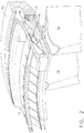
- Figures 1 and 2 depict a portion of a high pressure turbine in gas turbine engine.
- a row of airfoil-shaped turbine blades 10 are carried by a rotating disk (not shown) in a conventional manner. It will be understood that the disk rotates about a longitudinal central axis of the engine.
- the blades 10 are surrounded by an annular turbine shroud 12 which is supported within the central aperture of an encircling support member.
- the support member is an annular "shroud hanger" 14 which is itself supported by a stationary casing (not shown).
- the shroud hanger 14 may be continuous or segmented.
- the shroud 12 is a one-piece 360° component. It is generally cylindrical and has a radially inner flowpath surface 16 and an a radially outer back surface 18.
- the cross-sectional shape of the shroud 12 includes, from front to rear, a first generally cylindrical portion 20, a raised step 22, a radially-outwardly-extending flange 24, and a second generally cylindrical portion 26. As best seen in Figure 2 , one or more longitudinal grooves 28 are formed in the step 22.
- the shroud 12 is constructed from a ceramic matrix composite (CMC) material of a known type.
- CMC materials include a ceramic type fiber for example SiC, forms of which are coated with a compliant material such as Boron Nitride (BN). The fibers are carried in a ceramic type matrix, one form of which is SiC.
- CMC type materials have a room temperature tensile ductility of no greater than about 1%, herein used to define and mean a low tensile ductility material.
- CMC type materials have a room temperature tensile ductility in the range of about 0.4 to about 0.7%. This is compared with metals having a room temperature tensile ductility of at least about 5%, for example in the range of about 5 to about 15%.
- the shroud 12 could also be constructed from other low-ductility, high-temperature-capable materials.
- the flowpath surface 16 of the shroud 12 is coated with a layer of an abradable material 30 of a known type suitable for use with CMC materials. This layer is sometimes referred to as a "rub coat".
- the abradable material 30 is about 0.762 mm (0.030 in.) thick.
- a spring 32 is disposed between the shroud hanger 14 and the shroud 12 and serves to provide a radial centering force on the shroud 12.
- the spring 32 is a continuous ring with a cylindrical portion 34 and an array of longitudinally-extending spring fingers 36 that press against the first generally cylindrical portion 20 of the shroud 12, in an inboard direction.
- the shroud hanger 14 is generally "L" shaped in cross-section and includes an axially-extending body 38 and a radially-inwardly-extending flange 40. It may be a continuous ring or segmented. The flange 40 bears against the forward edge of the shroud 12 and restrains it from moving axially forward.
- One or more anti-rotation pins 48 are carried by the shroud hanger 14. Three or more equally-spaced anti-rotation pins 48 provide complete centering of the shroud 12. The outer end of each anti-rotation pin 48 is securely retained in the shroud hanger 14, for example by interference fit, mechanical fit, or bonding (e.g. welding or brazing). The anti-rotation pins 48extend radially inward and are received in the grooves 28. The anti-rotation pins 48 and the grooves 28 are sized to provide a tight fit in a tangential direction in order to provide effective anti-rotation.
- the term "tight fit" means that the shroud 12 has the minimum practical clearance in the tangential direction, while also being free to move radially relative to the anti-rotation pin 48.
- the gap between the groove 28 and the end of the anti-rotation pin 48 is sized so that radially outward movement of the shroud 12 will be stopped by the anti-rotation pin 48 before the turbine blade 10 can penetrate the abradable material 30 and contact the CMC portion of the shroud 12.
- the range of motion permitted by the anti-rotation pin 48 is less than the thickness of the abradable material 30. This configuration prevents severe blade tip damage.
- anti-rotation may be provided as an integral feature of the shroud hanger 14.
- Figure 3 illustrates a shroud hanger 14' with an integral pin 48' extending from a radially inner end of a flange 40'. The pin 48' is received in a blind slot 28' formed at the forward end of the shroud 12'.
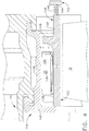
- the shroud 112 is a one-piece 360° component constructed from a ceramic matrix composite (CMC) material as described above, and may include an abradable material or "rub coat” as described above (not shown).
- the shroud 112 is generally cylindrical and has a radially inner flowpath surface 122 and an a radially outer back surface 124.
- the cross-sectional shape bounded by the back surface 124 includes, from front to rear, a first generally cylindrical portion 126, a radially-outwardly-extending flange 128, and a second generally cylindrical portion 130.
- one or more longitudinal ribs 132 extend radially outward from the back surface 124.
- the shroud hanger 114 is generally "L" shaped in cross-section and includes an axially-extending body 138 and a radially-inwardly-extending flange 140 (see Figure 4 ). It may be a continuous ring or segmented. The flange 140 bears against the forward edge of the shroud 112 and restrains it from moving axially forward.
- a static element 142 is disposed just aft of the shroud 112.
- the static element 142 is a portion of a second-stage turbine nozzle.
- the primary function of the static element 142 is not critical to the present invention, which may also be implemented in a single-stage turbine.
- the static element 142 includes an axially-forward facing front face 144.
- a spring element 146 is disposed between the front face 144 and the shroud 112 and serves to elastically load the shroud 112 against the flange 140 of the shroud hanger 114.
- the spring element 146 is an annular "W" seal with a convoluted cross-section. The shroud 112 is free to move against the spring element 146 as it expands and contracts without breakage.
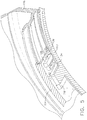
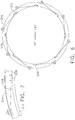
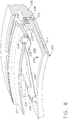
- FIGS. 6-8 depict an alternative shroud 212 supported by a support member, this embodiment not being part of the claimed invention.
- the support member is an annular "shroud hanger" 214 which is itself supported by a stationary casing (not shown) . It is also here not critical whether or not a separate shroud hanger 214 is present, as the shroud 212 may be mounted directly to the casing.
- the shroud 212 is a one-piece 360° component constructed from a ceramic matrix composite (CMC) material as described above, and may include an abradable material or "rub coat” as described above (not shown).
- the shroud 212 is generally cylindrical and has a radially inner flowpath surface 216 and an a radially outer back surface 218.
- the cross-sectional shape bounded by the back surface 218 includes, from front to rear, a first generally cylindrical portion 220, a radially-outwardly-extending flange 222, and a second generally cylindrical portion 224.
- One or more longitudinal ribs 226 extend radially outward from the back surface 218.
- Each spring 228 is substantially rigid in the tangential direction, and will oppose radial forces acting on the shroud at a location 90° from the spring 228. In combination they serve to provide complete radial centering of the shroud 212, while allowing thermal (diametrical) growth.
- the forward end of the shroud hanger 214 is not shown in Figure 8 .
- it is generally "L" shaped in cross-section and includes a radially-inwardly-extending flange which bears against the forward edge of the shroud 212 to restrain the shroud 212 from moving axially forward.
- a static element 236 including an axially-forward facing front face 238 is disposed just aft of the shroud 212.
- a spring element 240 is disposed between the front face 238 and the shroud 212 and serves to elastically load the shroud 212 against the shroud hanger 214.
- the shroud 212 is free to move against the spring element 240 as it expands and contracts without breakage.
- the shroud and mounting apparatus described herein has several advantages over a conventional design.
- the mounting apparatus supports and center the shroud within the turbine case while allowing for unrestricted radial growth.
- a single piece, 360 degree CMC turbine shroud ring weighs less (approximately 66% reduction) and utilizes less cooling flow (approximately 50%) compared to prior art shroud designs.
- the associated part count reduction (approximately 80%) improves maintainability of the turbine.
Landscapes
- Engineering & Computer Science (AREA)
- Mechanical Engineering (AREA)
- General Engineering & Computer Science (AREA)
- Turbine Rotor Nozzle Sealing (AREA)
Applications Claiming Priority (1)
| Application Number | Priority Date | Filing Date | Title |
|---|---|---|---|
| US12/696,566 US8079807B2 (en) | 2010-01-29 | 2010-01-29 | Mounting apparatus for low-ductility turbine shroud |
Publications (3)
| Publication Number | Publication Date |
|---|---|
| EP2357322A2 EP2357322A2 (en) | 2011-08-17 |
| EP2357322A3 EP2357322A3 (en) | 2011-11-16 |
| EP2357322B1 true EP2357322B1 (en) | 2020-01-01 |
Family
ID=43733160
Family Applications (1)
| Application Number | Title | Priority Date | Filing Date |
|---|---|---|---|
| EP11152436.9A Active EP2357322B1 (en) | 2010-01-29 | 2011-01-27 | Mounting apparatus for low-ductility turbine shroud |
Country Status (4)
| Country | Link |
|---|---|
| US (1) | US8079807B2 (enExample) |
| EP (1) | EP2357322B1 (enExample) |
| JP (1) | JP6183943B2 (enExample) |
| CA (1) | CA2729528C (enExample) |
Families Citing this family (77)
| Publication number | Priority date | Publication date | Assignee | Title |
|---|---|---|---|---|
| US8568091B2 (en) * | 2008-02-18 | 2013-10-29 | United Technologies Corporation | Gas turbine engine systems and methods involving blade outer air seals |
| FR2938873B1 (fr) * | 2008-11-21 | 2014-06-27 | Turbomeca | Organe de positionnement pour segment d'anneau |
| FR2964145B1 (fr) * | 2010-08-26 | 2018-06-15 | Safran Helicopter Engines | Procede d'accrochage de blindage sur carter de turbine et ensemble d'accrochage pour sa mise en oeuvre |
| US8998573B2 (en) * | 2010-10-29 | 2015-04-07 | General Electric Company | Resilient mounting apparatus for low-ductility turbine shroud |
| US8985944B2 (en) | 2011-03-30 | 2015-03-24 | General Electric Company | Continuous ring composite turbine shroud |
| US20130011248A1 (en) * | 2011-07-05 | 2013-01-10 | United Technologies Corporation | Reduction in thermal stresses in monolithic ceramic or ceramic matrix composite shroud |
| US9726043B2 (en) | 2011-12-15 | 2017-08-08 | General Electric Company | Mounting apparatus for low-ductility turbine shroud |
| US9255489B2 (en) * | 2012-02-06 | 2016-02-09 | United Technologies Corporation | Clearance control for gas turbine engine section |
| US9551238B2 (en) * | 2012-09-28 | 2017-01-24 | United Technologies Corporation | Pin connector for ceramic matrix composite turbine frame |
| US9771818B2 (en) * | 2012-12-29 | 2017-09-26 | United Technologies Corporation | Seals for a circumferential stop ring in a turbine exhaust case |
| WO2014120334A1 (en) * | 2013-01-29 | 2014-08-07 | Sippel Aaron D | Turbine shroud |
| GB201302125D0 (en) * | 2013-02-07 | 2013-03-20 | Rolls Royce Plc | A panel mounting arrangement |
| CA2900687C (en) * | 2013-03-05 | 2019-06-18 | Rolls-Royce Corporation | Structure and method for providing compliance and sealing between ceramic and metallic structures |
| EP2971577B1 (en) | 2013-03-13 | 2018-08-29 | Rolls-Royce Corporation | Turbine shroud |
| JP6114878B2 (ja) | 2013-05-17 | 2017-04-12 | ゼネラル・エレクトリック・カンパニイ | Cmcシュラウド支持システム |
| JP6643225B2 (ja) * | 2013-06-11 | 2020-02-12 | ゼネラル・エレクトリック・カンパニイ | クリアランス制御リング組立体 |
| GB2517203B (en) * | 2013-08-16 | 2016-07-20 | Rolls Royce Plc | A panel attachment system |
| WO2015041753A1 (en) * | 2013-09-18 | 2015-03-26 | United Technologies Corporation | Splined honeycomb seals |
| US9206700B2 (en) * | 2013-10-25 | 2015-12-08 | Siemens Aktiengesellschaft | Outer vane support ring including a strong back plate in a compressor section of a gas turbine engine |
| EP2881545B1 (de) * | 2013-12-04 | 2017-05-31 | MTU Aero Engines GmbH | Dichtelement, Dichteinrichtung und Strömungsmaschine |
| JP6529013B2 (ja) | 2013-12-12 | 2019-06-12 | ゼネラル・エレクトリック・カンパニイ | Cmcシュラウド支持システム |
| EP3102794B1 (en) | 2014-01-27 | 2019-12-18 | United Technologies Corporation | Blade outer air seal mount |
| CA2951431C (en) | 2014-06-12 | 2019-03-26 | General Electric Company | Multi-piece shroud hanger assembly |
| US11668207B2 (en) | 2014-06-12 | 2023-06-06 | General Electric Company | Shroud hanger assembly |
| US10400619B2 (en) | 2014-06-12 | 2019-09-03 | General Electric Company | Shroud hanger assembly |
| FR3022944B1 (fr) * | 2014-06-26 | 2020-02-14 | Safran Aircraft Engines | Ensemble rotatif pour turbomachine |
| US9945243B2 (en) | 2014-10-14 | 2018-04-17 | Rolls-Royce Corporation | Turbine shroud with biased blade track |
| US10190434B2 (en) | 2014-10-29 | 2019-01-29 | Rolls-Royce North American Technologies Inc. | Turbine shroud with locating inserts |
| US9976435B2 (en) * | 2014-12-19 | 2018-05-22 | United Technologies Corporation | Blade tip clearance systems |
| CA2915246A1 (en) | 2014-12-23 | 2016-06-23 | Rolls-Royce Corporation | Turbine shroud |
| CA2915370A1 (en) | 2014-12-23 | 2016-06-23 | Rolls-Royce Corporation | Full hoop blade track with axially keyed features |
| US10337353B2 (en) * | 2014-12-31 | 2019-07-02 | General Electric Company | Casing ring assembly with flowpath conduction cut |
| EP3045674B1 (en) | 2015-01-15 | 2018-11-21 | Rolls-Royce Corporation | Turbine shroud with tubular runner-locating inserts |
| US9874104B2 (en) | 2015-02-27 | 2018-01-23 | General Electric Company | Method and system for a ceramic matrix composite shroud hanger assembly |
| US10422244B2 (en) | 2015-03-16 | 2019-09-24 | General Electric Company | System for cooling a turbine shroud |
| US10100649B2 (en) | 2015-03-31 | 2018-10-16 | Rolls-Royce North American Technologies Inc. | Compliant rail hanger |
| CA2925588A1 (en) | 2015-04-29 | 2016-10-29 | Rolls-Royce Corporation | Brazed blade track for a gas turbine engine |
| CA2924855A1 (en) | 2015-04-29 | 2016-10-29 | Rolls-Royce Corporation | Keystoned blade track |
| US9828879B2 (en) | 2015-05-11 | 2017-11-28 | General Electric Company | Shroud retention system with keyed retention clips |
| US9945242B2 (en) * | 2015-05-11 | 2018-04-17 | General Electric Company | System for thermally isolating a turbine shroud |
| US9932901B2 (en) | 2015-05-11 | 2018-04-03 | General Electric Company | Shroud retention system with retention springs |
| US10221713B2 (en) | 2015-05-26 | 2019-03-05 | Rolls-Royce Corporation | Shroud cartridge having a ceramic matrix composite seal segment |
| US10370998B2 (en) | 2015-05-26 | 2019-08-06 | Rolls-Royce Corporation | Flexibly mounted ceramic matrix composite seal segments |
| US10087770B2 (en) | 2015-05-26 | 2018-10-02 | Rolls-Royce Corporation | Shroud cartridge having a ceramic matrix composite seal segment |
| US10370997B2 (en) | 2015-05-26 | 2019-08-06 | Rolls-Royce Corporation | Turbine shroud having ceramic matrix composite seal segment |
| US9963990B2 (en) | 2015-05-26 | 2018-05-08 | Rolls-Royce North American Technologies, Inc. | Ceramic matrix composite seal segment for a gas turbine engine |
| GB2541359A (en) * | 2015-06-25 | 2017-02-22 | S S Tube Tech Ltd | Ceramic composite component and support assembly |
| US10443417B2 (en) * | 2015-09-18 | 2019-10-15 | General Electric Company | Ceramic matrix composite ring shroud retention methods-finger seals with stepped shroud interface |
| US10077782B2 (en) | 2015-09-30 | 2018-09-18 | Siemens Aktiengesellschaft | Adaptive blade tip seal assembly |
| US10030542B2 (en) * | 2015-10-02 | 2018-07-24 | Honeywell International Inc. | Compliant coupling systems and methods for shrouds |
| GB201521937D0 (en) * | 2015-12-14 | 2016-01-27 | Rolls Royce Plc | Gas turbine engine turbine cooling system |
| US10240476B2 (en) | 2016-01-19 | 2019-03-26 | Rolls-Royce North American Technologies Inc. | Full hoop blade track with interstage cooling air |
| US9970310B2 (en) | 2016-01-21 | 2018-05-15 | United Technologies Corporation | System and method for an assembled ring shroud |
| US10138750B2 (en) * | 2016-03-16 | 2018-11-27 | United Technologies Corporation | Boas segmented heat shield |
| US10443616B2 (en) * | 2016-03-16 | 2019-10-15 | United Technologies Corporation | Blade outer air seal with centrally mounted seal arc segments |
| US10415415B2 (en) | 2016-07-22 | 2019-09-17 | Rolls-Royce North American Technologies Inc. | Turbine shroud with forward case and full hoop blade track |
| US10287906B2 (en) | 2016-05-24 | 2019-05-14 | Rolls-Royce North American Technologies Inc. | Turbine shroud with full hoop ceramic matrix composite blade track and seal system |
| US10746037B2 (en) | 2016-11-30 | 2020-08-18 | Rolls-Royce Corporation | Turbine shroud assembly with tandem seals |
| US10344612B2 (en) | 2017-01-13 | 2019-07-09 | United Technologies Corporation | Compact advanced passive tip clearance control |
| US10480337B2 (en) | 2017-04-18 | 2019-11-19 | Rolls-Royce North American Technologies Inc. | Turbine shroud assembly with multi-piece seals |
| FR3065481B1 (fr) * | 2017-04-19 | 2020-07-17 | Safran Aircraft Engines | Ensemble pour turbine, notamment pour une turbomachine |
| US10533446B2 (en) | 2017-05-15 | 2020-01-14 | United Technologies Corporation | Alternative W-seal groove arrangement |
| US10364707B2 (en) * | 2017-06-16 | 2019-07-30 | General Electric Company | Retention assembly for gas turbine engine components |
| US10392957B2 (en) | 2017-10-05 | 2019-08-27 | Rolls-Royce Corporation | Ceramic matrix composite blade track with mounting system having load distribution features |
| US10619514B2 (en) | 2017-10-18 | 2020-04-14 | Rolls-Royce Corporation | Ceramic matrix composite assembly with compliant pin attachment features |
| US11802486B2 (en) * | 2017-11-13 | 2023-10-31 | General Electric Company | CMC component and fabrication using mechanical joints |
| US10801350B2 (en) | 2018-02-23 | 2020-10-13 | Rolls-Royce Corporation | Actively cooled engine assembly with ceramic matrix composite components |
| US10724390B2 (en) * | 2018-03-16 | 2020-07-28 | General Electric Company | Collar support assembly for airfoils |
| US10711630B2 (en) * | 2018-03-20 | 2020-07-14 | Honeywell International Inc. | Retention and control system for turbine shroud ring |
| US10934877B2 (en) | 2018-10-31 | 2021-03-02 | Raytheon Technologies Corporation | CMC laminate pocket BOAS with axial attachment scheme |
| US11008894B2 (en) | 2018-10-31 | 2021-05-18 | Raytheon Technologies Corporation | BOAS spring clip |
| FR3103523B1 (fr) * | 2019-11-26 | 2021-11-05 | Safran Aircraft Engines | Dispositif d’équilibrage |
| US11326476B1 (en) * | 2020-10-22 | 2022-05-10 | Honeywell International Inc. | Compliant retention system for gas turbine engine |
| US11959389B2 (en) * | 2021-06-11 | 2024-04-16 | Pratt & Whitney Canada Corp. | Turbine shroud segments with angular locating feature |
| US12188359B2 (en) | 2022-09-30 | 2025-01-07 | Rtx Corporation | Blade outer air seal with retainer ring |
| US12416242B2 (en) | 2022-09-30 | 2025-09-16 | Rtx Corporation | Blade outer air seal with compliant seal |
| FR3155869A1 (fr) * | 2023-11-27 | 2025-05-30 | Safran Nacelles | Procédé de montage de deux pièces l’une sur l’autre par matage sacrificiel et assemblage ainsi réalisé |
Citations (2)
| Publication number | Priority date | Publication date | Assignee | Title |
|---|---|---|---|---|
| US20050152777A1 (en) * | 2004-01-08 | 2005-07-14 | Thompson Jeff B. | Resilent seal on leading edge of turbine inner shroud |
| US20080073861A1 (en) * | 2004-02-20 | 2008-03-27 | Eagle Engineering Aerospace Co., Ltd. | Seal device |
Family Cites Families (20)
| Publication number | Priority date | Publication date | Assignee | Title |
|---|---|---|---|---|
| US4411594A (en) | 1979-06-30 | 1983-10-25 | Rolls-Royce Limited | Support member and a component supported thereby |
| GB2254378B (en) | 1981-12-30 | 1993-03-31 | Rolls Royce | Gas turbine engine ring shroud ring mounting |
| FR2580033A1 (en) | 1985-04-03 | 1986-10-10 | Snecma | Elastically suspended turbine ring for a turbine machine |
| US5074748A (en) | 1990-07-30 | 1991-12-24 | General Electric Company | Seal assembly for segmented turbine engine structures |
| US5154577A (en) | 1991-01-17 | 1992-10-13 | General Electric Company | Flexible three-piece seal assembly |
| US5188507A (en) | 1991-11-27 | 1993-02-23 | General Electric Company | Low-pressure turbine shroud |
| US5927942A (en) | 1993-10-27 | 1999-07-27 | United Technologies Corporation | Mounting and sealing arrangement for a turbine shroud segment |
| US5423659A (en) * | 1994-04-28 | 1995-06-13 | United Technologies Corporation | Shroud segment having a cut-back retaining hook |
| US5655876A (en) | 1996-01-02 | 1997-08-12 | General Electric Company | Low leakage turbine nozzle |
| US6290459B1 (en) | 1999-11-01 | 2001-09-18 | General Electric Company | Stationary flowpath components for gas turbine engines |
| US6340285B1 (en) | 2000-06-08 | 2002-01-22 | General Electric Company | End rail cooling for combined high and low pressure turbine shroud |
| US6503051B2 (en) | 2001-06-06 | 2003-01-07 | General Electric Company | Overlapping interference seal and methods for forming the seal |
| US6733233B2 (en) * | 2002-04-26 | 2004-05-11 | Pratt & Whitney Canada Corp. | Attachment of a ceramic shroud in a metal housing |
| JP2004036443A (ja) * | 2002-07-02 | 2004-02-05 | Ishikawajima Harima Heavy Ind Co Ltd | ガスタービンシュラウド構造 |
| DE10247355A1 (de) * | 2002-10-10 | 2004-04-22 | Rolls-Royce Deutschland Ltd & Co Kg | Turbinendeckbandsegmentbefestigung |
| US6896484B2 (en) * | 2003-09-12 | 2005-05-24 | Siemens Westinghouse Power Corporation | Turbine engine sealing device |
| FR2875851B1 (fr) * | 2004-09-28 | 2006-12-29 | Snecma Moteurs Sa | Dispositif d'etancheite dispose entre un compresseur haute-pression et un diffuseur de turbomachine |
| GB0703827D0 (en) | 2007-02-28 | 2007-04-11 | Rolls Royce Plc | Rotor seal segment |
| FR2914707B1 (fr) | 2007-04-05 | 2009-10-30 | Snecma Propulsion Solide Sa | Procede d'assemblage avec recouvrement de deux pieces ayant des coefficients de dilatation differents et assemblage ainsi obtenu |
| DE102009003638A1 (de) * | 2008-03-31 | 2009-10-01 | General Electric Co. | System und Verfahren zur Halterung von Statorkomponenten |
-
2010
- 2010-01-29 US US12/696,566 patent/US8079807B2/en active Active
-
2011
- 2011-01-27 EP EP11152436.9A patent/EP2357322B1/en active Active
- 2011-01-27 CA CA2729528A patent/CA2729528C/en active Active
- 2011-01-28 JP JP2011015939A patent/JP6183943B2/ja active Active
Patent Citations (2)
| Publication number | Priority date | Publication date | Assignee | Title |
|---|---|---|---|---|
| US20050152777A1 (en) * | 2004-01-08 | 2005-07-14 | Thompson Jeff B. | Resilent seal on leading edge of turbine inner shroud |
| US20080073861A1 (en) * | 2004-02-20 | 2008-03-27 | Eagle Engineering Aerospace Co., Ltd. | Seal device |
Also Published As
| Publication number | Publication date |
|---|---|
| CA2729528A1 (en) | 2011-07-29 |
| US20110189009A1 (en) | 2011-08-04 |
| CA2729528C (en) | 2012-11-20 |
| JP2011157968A (ja) | 2011-08-18 |
| EP2357322A3 (en) | 2011-11-16 |
| US8079807B2 (en) | 2011-12-20 |
| JP6183943B2 (ja) | 2017-08-23 |
| EP2357322A2 (en) | 2011-08-17 |
Similar Documents
| Publication | Publication Date | Title |
|---|---|---|
| EP2357322B1 (en) | Mounting apparatus for low-ductility turbine shroud | |
| US8740552B2 (en) | Low-ductility turbine shroud and mounting apparatus | |
| EP2466073B1 (en) | Low-ductility turbine flowpath apparatus | |
| US8998573B2 (en) | Resilient mounting apparatus for low-ductility turbine shroud | |
| US9726043B2 (en) | Mounting apparatus for low-ductility turbine shroud | |
| EP2540994B1 (en) | Chordal mounting arrangement for low-ductility turbine shroud | |
| US8579580B2 (en) | Mounting apparatus for low-ductility turbine shroud | |
| US8753073B2 (en) | Turbine shroud sealing apparatus | |
| EP1643084B1 (en) | Turbine engine shroud segment, hanger and assembly | |
| EP3091187B1 (en) | Turbine component assembly with thermally stress-free fastener | |
| US20140212284A1 (en) | Hybrid turbine nozzle |
Legal Events
| Date | Code | Title | Description |
|---|---|---|---|
| PUAI | Public reference made under article 153(3) epc to a published international application that has entered the european phase |
Free format text: ORIGINAL CODE: 0009012 |
|
| AK | Designated contracting states |
Kind code of ref document: A2 Designated state(s): AL AT BE BG CH CY CZ DE DK EE ES FI FR GB GR HR HU IE IS IT LI LT LU LV MC MK MT NL NO PL PT RO RS SE SI SK SM TR |
|
| AX | Request for extension of the european patent |
Extension state: BA ME |
|
| PUAL | Search report despatched |
Free format text: ORIGINAL CODE: 0009013 |
|
| AK | Designated contracting states |
Kind code of ref document: A3 Designated state(s): AL AT BE BG CH CY CZ DE DK EE ES FI FR GB GR HR HU IE IS IT LI LT LU LV MC MK MT NL NO PL PT RO RS SE SI SK SM TR |
|
| AX | Request for extension of the european patent |
Extension state: BA ME |
|
| RIC1 | Information provided on ipc code assigned before grant |
Ipc: F01D 11/12 20060101ALI20111012BHEP Ipc: F01D 25/24 20060101AFI20111012BHEP |
|
| 17P | Request for examination filed |
Effective date: 20120516 |
|
| STAA | Information on the status of an ep patent application or granted ep patent |
Free format text: STATUS: EXAMINATION IS IN PROGRESS |
|
| 17Q | First examination report despatched |
Effective date: 20180111 |
|
| GRAP | Despatch of communication of intention to grant a patent |
Free format text: ORIGINAL CODE: EPIDOSNIGR1 |
|
| STAA | Information on the status of an ep patent application or granted ep patent |
Free format text: STATUS: GRANT OF PATENT IS INTENDED |
|
| INTG | Intention to grant announced |
Effective date: 20190207 |
|
| GRAJ | Information related to disapproval of communication of intention to grant by the applicant or resumption of examination proceedings by the epo deleted |
Free format text: ORIGINAL CODE: EPIDOSDIGR1 |
|
| STAA | Information on the status of an ep patent application or granted ep patent |
Free format text: STATUS: EXAMINATION IS IN PROGRESS |
|
| GRAP | Despatch of communication of intention to grant a patent |
Free format text: ORIGINAL CODE: EPIDOSNIGR1 |
|
| STAA | Information on the status of an ep patent application or granted ep patent |
Free format text: STATUS: GRANT OF PATENT IS INTENDED |
|
| INTC | Intention to grant announced (deleted) | ||
| INTG | Intention to grant announced |
Effective date: 20190711 |
|
| GRAS | Grant fee paid |
Free format text: ORIGINAL CODE: EPIDOSNIGR3 |
|
| GRAA | (expected) grant |
Free format text: ORIGINAL CODE: 0009210 |
|
| STAA | Information on the status of an ep patent application or granted ep patent |
Free format text: STATUS: THE PATENT HAS BEEN GRANTED |
|
| AK | Designated contracting states |
Kind code of ref document: B1 Designated state(s): AL AT BE BG CH CY CZ DE DK EE ES FI FR GB GR HR HU IE IS IT LI LT LU LV MC MK MT NL NO PL PT RO RS SE SI SK SM TR |
|
| REG | Reference to a national code |
Ref country code: GB Ref legal event code: FG4D |
|
| REG | Reference to a national code |
Ref country code: CH Ref legal event code: EP Ref country code: AT Ref legal event code: REF Ref document number: 1220037 Country of ref document: AT Kind code of ref document: T Effective date: 20200115 |
|
| REG | Reference to a national code |
Ref country code: IE Ref legal event code: FG4D |
|
| REG | Reference to a national code |
Ref country code: DE Ref legal event code: R096 Ref document number: 602011064318 Country of ref document: DE |
|
| REG | Reference to a national code |
Ref country code: NL Ref legal event code: MP Effective date: 20200101 |
|
| REG | Reference to a national code |
Ref country code: LT Ref legal event code: MG4D |
|
| PG25 | Lapsed in a contracting state [announced via postgrant information from national office to epo] |
Ref country code: CZ Free format text: LAPSE BECAUSE OF FAILURE TO SUBMIT A TRANSLATION OF THE DESCRIPTION OR TO PAY THE FEE WITHIN THE PRESCRIBED TIME-LIMIT Effective date: 20200101 Ref country code: NO Free format text: LAPSE BECAUSE OF FAILURE TO SUBMIT A TRANSLATION OF THE DESCRIPTION OR TO PAY THE FEE WITHIN THE PRESCRIBED TIME-LIMIT Effective date: 20200401 Ref country code: FI Free format text: LAPSE BECAUSE OF FAILURE TO SUBMIT A TRANSLATION OF THE DESCRIPTION OR TO PAY THE FEE WITHIN THE PRESCRIBED TIME-LIMIT Effective date: 20200101 Ref country code: NL Free format text: LAPSE BECAUSE OF FAILURE TO SUBMIT A TRANSLATION OF THE DESCRIPTION OR TO PAY THE FEE WITHIN THE PRESCRIBED TIME-LIMIT Effective date: 20200101 Ref country code: RS Free format text: LAPSE BECAUSE OF FAILURE TO SUBMIT A TRANSLATION OF THE DESCRIPTION OR TO PAY THE FEE WITHIN THE PRESCRIBED TIME-LIMIT Effective date: 20200101 Ref country code: PT Free format text: LAPSE BECAUSE OF FAILURE TO SUBMIT A TRANSLATION OF THE DESCRIPTION OR TO PAY THE FEE WITHIN THE PRESCRIBED TIME-LIMIT Effective date: 20200527 Ref country code: LT Free format text: LAPSE BECAUSE OF FAILURE TO SUBMIT A TRANSLATION OF THE DESCRIPTION OR TO PAY THE FEE WITHIN THE PRESCRIBED TIME-LIMIT Effective date: 20200101 |
|
| PG25 | Lapsed in a contracting state [announced via postgrant information from national office to epo] |
Ref country code: IS Free format text: LAPSE BECAUSE OF FAILURE TO SUBMIT A TRANSLATION OF THE DESCRIPTION OR TO PAY THE FEE WITHIN THE PRESCRIBED TIME-LIMIT Effective date: 20200501 Ref country code: GR Free format text: LAPSE BECAUSE OF FAILURE TO SUBMIT A TRANSLATION OF THE DESCRIPTION OR TO PAY THE FEE WITHIN THE PRESCRIBED TIME-LIMIT Effective date: 20200402 Ref country code: BG Free format text: LAPSE BECAUSE OF FAILURE TO SUBMIT A TRANSLATION OF THE DESCRIPTION OR TO PAY THE FEE WITHIN THE PRESCRIBED TIME-LIMIT Effective date: 20200401 Ref country code: LV Free format text: LAPSE BECAUSE OF FAILURE TO SUBMIT A TRANSLATION OF THE DESCRIPTION OR TO PAY THE FEE WITHIN THE PRESCRIBED TIME-LIMIT Effective date: 20200101 Ref country code: SE Free format text: LAPSE BECAUSE OF FAILURE TO SUBMIT A TRANSLATION OF THE DESCRIPTION OR TO PAY THE FEE WITHIN THE PRESCRIBED TIME-LIMIT Effective date: 20200101 Ref country code: HR Free format text: LAPSE BECAUSE OF FAILURE TO SUBMIT A TRANSLATION OF THE DESCRIPTION OR TO PAY THE FEE WITHIN THE PRESCRIBED TIME-LIMIT Effective date: 20200101 |
|
| REG | Reference to a national code |
Ref country code: CH Ref legal event code: PL |
|
| REG | Reference to a national code |
Ref country code: DE Ref legal event code: R097 Ref document number: 602011064318 Country of ref document: DE |
|
| REG | Reference to a national code |
Ref country code: BE Ref legal event code: MM Effective date: 20200131 |
|
| PG25 | Lapsed in a contracting state [announced via postgrant information from national office to epo] |
Ref country code: DK Free format text: LAPSE BECAUSE OF FAILURE TO SUBMIT A TRANSLATION OF THE DESCRIPTION OR TO PAY THE FEE WITHIN THE PRESCRIBED TIME-LIMIT Effective date: 20200101 Ref country code: ES Free format text: LAPSE BECAUSE OF FAILURE TO SUBMIT A TRANSLATION OF THE DESCRIPTION OR TO PAY THE FEE WITHIN THE PRESCRIBED TIME-LIMIT Effective date: 20200101 Ref country code: LU Free format text: LAPSE BECAUSE OF NON-PAYMENT OF DUE FEES Effective date: 20200127 Ref country code: MC Free format text: LAPSE BECAUSE OF FAILURE TO SUBMIT A TRANSLATION OF THE DESCRIPTION OR TO PAY THE FEE WITHIN THE PRESCRIBED TIME-LIMIT Effective date: 20200101 Ref country code: SK Free format text: LAPSE BECAUSE OF FAILURE TO SUBMIT A TRANSLATION OF THE DESCRIPTION OR TO PAY THE FEE WITHIN THE PRESCRIBED TIME-LIMIT Effective date: 20200101 Ref country code: RO Free format text: LAPSE BECAUSE OF FAILURE TO SUBMIT A TRANSLATION OF THE DESCRIPTION OR TO PAY THE FEE WITHIN THE PRESCRIBED TIME-LIMIT Effective date: 20200101 Ref country code: EE Free format text: LAPSE BECAUSE OF FAILURE TO SUBMIT A TRANSLATION OF THE DESCRIPTION OR TO PAY THE FEE WITHIN THE PRESCRIBED TIME-LIMIT Effective date: 20200101 Ref country code: SM Free format text: LAPSE BECAUSE OF FAILURE TO SUBMIT A TRANSLATION OF THE DESCRIPTION OR TO PAY THE FEE WITHIN THE PRESCRIBED TIME-LIMIT Effective date: 20200101 |
|
| PLBE | No opposition filed within time limit |
Free format text: ORIGINAL CODE: 0009261 |
|
| STAA | Information on the status of an ep patent application or granted ep patent |
Free format text: STATUS: NO OPPOSITION FILED WITHIN TIME LIMIT |
|
| REG | Reference to a national code |
Ref country code: AT Ref legal event code: MK05 Ref document number: 1220037 Country of ref document: AT Kind code of ref document: T Effective date: 20200101 |
|
| PG25 | Lapsed in a contracting state [announced via postgrant information from national office to epo] |
Ref country code: BE Free format text: LAPSE BECAUSE OF NON-PAYMENT OF DUE FEES Effective date: 20200131 Ref country code: LI Free format text: LAPSE BECAUSE OF NON-PAYMENT OF DUE FEES Effective date: 20200131 Ref country code: CH Free format text: LAPSE BECAUSE OF NON-PAYMENT OF DUE FEES Effective date: 20200131 |
|
| 26N | No opposition filed |
Effective date: 20201002 |
|
| PG25 | Lapsed in a contracting state [announced via postgrant information from national office to epo] |
Ref country code: IT Free format text: LAPSE BECAUSE OF FAILURE TO SUBMIT A TRANSLATION OF THE DESCRIPTION OR TO PAY THE FEE WITHIN THE PRESCRIBED TIME-LIMIT Effective date: 20200101 Ref country code: IE Free format text: LAPSE BECAUSE OF NON-PAYMENT OF DUE FEES Effective date: 20200127 Ref country code: AT Free format text: LAPSE BECAUSE OF FAILURE TO SUBMIT A TRANSLATION OF THE DESCRIPTION OR TO PAY THE FEE WITHIN THE PRESCRIBED TIME-LIMIT Effective date: 20200101 |
|
| PG25 | Lapsed in a contracting state [announced via postgrant information from national office to epo] |
Ref country code: PL Free format text: LAPSE BECAUSE OF FAILURE TO SUBMIT A TRANSLATION OF THE DESCRIPTION OR TO PAY THE FEE WITHIN THE PRESCRIBED TIME-LIMIT Effective date: 20200101 Ref country code: SI Free format text: LAPSE BECAUSE OF FAILURE TO SUBMIT A TRANSLATION OF THE DESCRIPTION OR TO PAY THE FEE WITHIN THE PRESCRIBED TIME-LIMIT Effective date: 20200101 |
|
| PG25 | Lapsed in a contracting state [announced via postgrant information from national office to epo] |
Ref country code: TR Free format text: LAPSE BECAUSE OF FAILURE TO SUBMIT A TRANSLATION OF THE DESCRIPTION OR TO PAY THE FEE WITHIN THE PRESCRIBED TIME-LIMIT Effective date: 20200101 Ref country code: MT Free format text: LAPSE BECAUSE OF FAILURE TO SUBMIT A TRANSLATION OF THE DESCRIPTION OR TO PAY THE FEE WITHIN THE PRESCRIBED TIME-LIMIT Effective date: 20200101 Ref country code: CY Free format text: LAPSE BECAUSE OF FAILURE TO SUBMIT A TRANSLATION OF THE DESCRIPTION OR TO PAY THE FEE WITHIN THE PRESCRIBED TIME-LIMIT Effective date: 20200101 |
|
| PG25 | Lapsed in a contracting state [announced via postgrant information from national office to epo] |
Ref country code: MK Free format text: LAPSE BECAUSE OF FAILURE TO SUBMIT A TRANSLATION OF THE DESCRIPTION OR TO PAY THE FEE WITHIN THE PRESCRIBED TIME-LIMIT Effective date: 20200101 Ref country code: AL Free format text: LAPSE BECAUSE OF FAILURE TO SUBMIT A TRANSLATION OF THE DESCRIPTION OR TO PAY THE FEE WITHIN THE PRESCRIBED TIME-LIMIT Effective date: 20200101 |
|
| P01 | Opt-out of the competence of the unified patent court (upc) registered |
Effective date: 20230414 |
|
| PGFP | Annual fee paid to national office [announced via postgrant information from national office to epo] |
Ref country code: GB Payment date: 20241219 Year of fee payment: 15 |
|
| PGFP | Annual fee paid to national office [announced via postgrant information from national office to epo] |
Ref country code: FR Payment date: 20241219 Year of fee payment: 15 |
|
| PGFP | Annual fee paid to national office [announced via postgrant information from national office to epo] |
Ref country code: DE Payment date: 20241218 Year of fee payment: 15 |