EP2466073B1 - Low-ductility turbine flowpath apparatus - Google Patents
Low-ductility turbine flowpath apparatus Download PDFInfo
- Publication number
- EP2466073B1 EP2466073B1 EP11191604.5A EP11191604A EP2466073B1 EP 2466073 B1 EP2466073 B1 EP 2466073B1 EP 11191604 A EP11191604 A EP 11191604A EP 2466073 B1 EP2466073 B1 EP 2466073B1
- Authority
- EP
- European Patent Office
- Prior art keywords
- flowpath
- annular
- flowpath member
- turbine
- centering spring
- Prior art date
- Legal status (The legal status is an assumption and is not a legal conclusion. Google has not performed a legal analysis and makes no representation as to the accuracy of the status listed.)
- Active
Links
- 239000000463 material Substances 0.000 claims description 21
- 239000011153 ceramic matrix composite Substances 0.000 claims description 14
- 239000007789 gas Substances 0.000 description 10
- 238000001816 cooling Methods 0.000 description 3
- XEEYBQQBJWHFJM-UHFFFAOYSA-N Iron Chemical compound [Fe] XEEYBQQBJWHFJM-UHFFFAOYSA-N 0.000 description 2
- 239000000919 ceramic Substances 0.000 description 2
- 239000000567 combustion gas Substances 0.000 description 2
- 239000000835 fiber Substances 0.000 description 2
- 239000000446 fuel Substances 0.000 description 2
- 238000009434 installation Methods 0.000 description 2
- 239000002184 metal Substances 0.000 description 2
- 229910052751 metal Inorganic materials 0.000 description 2
- 150000002739 metals Chemical class 0.000 description 2
- HBMJWWWQQXIZIP-UHFFFAOYSA-N silicon carbide Chemical compound [Si+]#[C-] HBMJWWWQQXIZIP-UHFFFAOYSA-N 0.000 description 2
- 230000007704 transition Effects 0.000 description 2
- PZNSFCLAULLKQX-UHFFFAOYSA-N Boron nitride Chemical compound N#B PZNSFCLAULLKQX-UHFFFAOYSA-N 0.000 description 1
- PXHVJJICTQNCMI-UHFFFAOYSA-N Nickel Chemical compound [Ni] PXHVJJICTQNCMI-UHFFFAOYSA-N 0.000 description 1
- 229910045601 alloy Inorganic materials 0.000 description 1
- 239000000956 alloy Substances 0.000 description 1
- 239000011248 coating agent Substances 0.000 description 1
- 238000000576 coating method Methods 0.000 description 1
- GUTLYIVDDKVIGB-UHFFFAOYSA-N cobalt atom Chemical compound [Co] GUTLYIVDDKVIGB-UHFFFAOYSA-N 0.000 description 1
- 230000001419 dependent effect Effects 0.000 description 1
- 238000010586 diagram Methods 0.000 description 1
- 230000008030 elimination Effects 0.000 description 1
- 238000003379 elimination reaction Methods 0.000 description 1
- 230000007613 environmental effect Effects 0.000 description 1
- 239000012530 fluid Substances 0.000 description 1
- NPURPEXKKDAKIH-UHFFFAOYSA-N iodoimino(oxo)methane Chemical compound IN=C=O NPURPEXKKDAKIH-UHFFFAOYSA-N 0.000 description 1
- 229910052742 iron Inorganic materials 0.000 description 1
- 239000011159 matrix material Substances 0.000 description 1
- 229910001092 metal group alloy Inorganic materials 0.000 description 1
- 239000007769 metal material Substances 0.000 description 1
- 238000000034 method Methods 0.000 description 1
- 230000036316 preload Effects 0.000 description 1
- 230000000452 restraining effect Effects 0.000 description 1
- 238000007789 sealing Methods 0.000 description 1
- 229910010271 silicon carbide Inorganic materials 0.000 description 1
- 229910000601 superalloy Inorganic materials 0.000 description 1
- 230000008646 thermal stress Effects 0.000 description 1
- 229910001247 waspaloy Inorganic materials 0.000 description 1
- 239000013585 weight reducing agent Substances 0.000 description 1
Images


Classifications
-
- F—MECHANICAL ENGINEERING; LIGHTING; HEATING; WEAPONS; BLASTING
- F01—MACHINES OR ENGINES IN GENERAL; ENGINE PLANTS IN GENERAL; STEAM ENGINES
- F01D—NON-POSITIVE DISPLACEMENT MACHINES OR ENGINES, e.g. STEAM TURBINES
- F01D9/00—Stators
- F01D9/02—Nozzles; Nozzle boxes; Stator blades; Guide conduits, e.g. individual nozzles
-
- F—MECHANICAL ENGINEERING; LIGHTING; HEATING; WEAPONS; BLASTING
- F01—MACHINES OR ENGINES IN GENERAL; ENGINE PLANTS IN GENERAL; STEAM ENGINES
- F01D—NON-POSITIVE DISPLACEMENT MACHINES OR ENGINES, e.g. STEAM TURBINES
- F01D11/00—Preventing or minimising internal leakage of working-fluid, e.g. between stages
- F01D11/08—Preventing or minimising internal leakage of working-fluid, e.g. between stages for sealing space between rotor blade tips and stator
-
- F—MECHANICAL ENGINEERING; LIGHTING; HEATING; WEAPONS; BLASTING
- F01—MACHINES OR ENGINES IN GENERAL; ENGINE PLANTS IN GENERAL; STEAM ENGINES
- F01D—NON-POSITIVE DISPLACEMENT MACHINES OR ENGINES, e.g. STEAM TURBINES
- F01D25/00—Component parts, details, or accessories, not provided for in, or of interest apart from, other groups
- F01D25/24—Casings; Casing parts, e.g. diaphragms, casing fastenings
- F01D25/246—Fastening of diaphragms or stator-rings
-
- F—MECHANICAL ENGINEERING; LIGHTING; HEATING; WEAPONS; BLASTING
- F05—INDEXING SCHEMES RELATING TO ENGINES OR PUMPS IN VARIOUS SUBCLASSES OF CLASSES F01-F04
- F05D—INDEXING SCHEME FOR ASPECTS RELATING TO NON-POSITIVE-DISPLACEMENT MACHINES OR ENGINES, GAS-TURBINES OR JET-PROPULSION PLANTS
- F05D2230/00—Manufacture
- F05D2230/60—Assembly methods
- F05D2230/64—Assembly methods using positioning or alignment devices for aligning or centring, e.g. pins
- F05D2230/642—Assembly methods using positioning or alignment devices for aligning or centring, e.g. pins using maintaining alignment while permitting differential dilatation
-
- F—MECHANICAL ENGINEERING; LIGHTING; HEATING; WEAPONS; BLASTING
- F05—INDEXING SCHEMES RELATING TO ENGINES OR PUMPS IN VARIOUS SUBCLASSES OF CLASSES F01-F04
- F05D—INDEXING SCHEME FOR ASPECTS RELATING TO NON-POSITIVE-DISPLACEMENT MACHINES OR ENGINES, GAS-TURBINES OR JET-PROPULSION PLANTS
- F05D2250/00—Geometry
- F05D2250/70—Shape
- F05D2250/75—Shape given by its similarity to a letter, e.g. T-shaped
-
- F—MECHANICAL ENGINEERING; LIGHTING; HEATING; WEAPONS; BLASTING
- F05—INDEXING SCHEMES RELATING TO ENGINES OR PUMPS IN VARIOUS SUBCLASSES OF CLASSES F01-F04
- F05D—INDEXING SCHEME FOR ASPECTS RELATING TO NON-POSITIVE-DISPLACEMENT MACHINES OR ENGINES, GAS-TURBINES OR JET-PROPULSION PLANTS
- F05D2260/00—Function
- F05D2260/30—Retaining components in desired mutual position
- F05D2260/38—Retaining components in desired mutual position by a spring, i.e. spring loaded or biased towards a certain position
-
- F—MECHANICAL ENGINEERING; LIGHTING; HEATING; WEAPONS; BLASTING
- F05—INDEXING SCHEMES RELATING TO ENGINES OR PUMPS IN VARIOUS SUBCLASSES OF CLASSES F01-F04
- F05D—INDEXING SCHEME FOR ASPECTS RELATING TO NON-POSITIVE-DISPLACEMENT MACHINES OR ENGINES, GAS-TURBINES OR JET-PROPULSION PLANTS
- F05D2300/00—Materials; Properties thereof
- F05D2300/50—Intrinsic material properties or characteristics
- F05D2300/518—Ductility
-
- F—MECHANICAL ENGINEERING; LIGHTING; HEATING; WEAPONS; BLASTING
- F05—INDEXING SCHEMES RELATING TO ENGINES OR PUMPS IN VARIOUS SUBCLASSES OF CLASSES F01-F04
- F05D—INDEXING SCHEME FOR ASPECTS RELATING TO NON-POSITIVE-DISPLACEMENT MACHINES OR ENGINES, GAS-TURBINES OR JET-PROPULSION PLANTS
- F05D2300/00—Materials; Properties thereof
- F05D2300/60—Properties or characteristics given to material by treatment or manufacturing
- F05D2300/603—Composites; e.g. fibre-reinforced
- F05D2300/6033—Ceramic matrix composites [CMC]
-
- Y—GENERAL TAGGING OF NEW TECHNOLOGICAL DEVELOPMENTS; GENERAL TAGGING OF CROSS-SECTIONAL TECHNOLOGIES SPANNING OVER SEVERAL SECTIONS OF THE IPC; TECHNICAL SUBJECTS COVERED BY FORMER USPC CROSS-REFERENCE ART COLLECTIONS [XRACs] AND DIGESTS
- Y02—TECHNOLOGIES OR APPLICATIONS FOR MITIGATION OR ADAPTATION AGAINST CLIMATE CHANGE
- Y02T—CLIMATE CHANGE MITIGATION TECHNOLOGIES RELATED TO TRANSPORTATION
- Y02T50/00—Aeronautics or air transport
- Y02T50/60—Efficient propulsion technologies, e.g. for aircraft
Definitions
- This invention relates generally to gas turbine engines, and more particularly to turbine flowpath components made of a low-ductility material in the turbine sections of such engines.
- a typical gas turbine engine includes one or more turbine rotors which extract energy from the primary gas flow.
- Each rotor comprises an annular array of blades or buckets carried by a rotating disk.
- the flowpath through the rotor is defined in part by a shroud, which is a stationary structure which circumscribes the tips of the blades or buckets.
- CMCs ceramic matrix composites
- CMC materials expand at different rates than surrounding metallic hardware, and are not as suitable as metals for forming small-scale mounting features such as hooks, grooves, rails, and the like.
- Conventional mechanical clamped joints are sometimes dependent on frictional forces which can be inconsistent when using a combination of metallic and CMC materials.
- US 2009/0053050 A1 relates to a gas turbine shroud support apparatus and discloses features generally corresponding to the preamble of claim 1.
- US 5,927,942 relates to a mounting and sealing arrangement for a turbine shroud segment.
- the present invention provides a turbine flowpath structure that serves as both a turbine shroud and a transition duct.
- the flowpath structure is made from a low-ductility material that does not require air cooling, and is trapped in place by surrounding hardware and centered by spring forces.
- a turbine flowpath apparatus for a gas turbine engine having a centerline axis.
- the apparatus includes: an annular flowpath member comprising ceramic matrix composite material, the flowpath member having a flowpath surface and an opposed back surface, and having a cross-sectional shape comprising a generally cylindrical forward section and an aft section that extends aft and radially outward at a non-perpendicular, non-parallel angle to the centerline axis; an annular stationary structure surrounding the flowpath member; and an annular centering spring disposed between the stationary structure and the flowpath member, the centering spring urging the flowpath member towards a centered position within the stationary structure.
- the apparatus further includes radial pins fixed to the centering spring and extending into corresponding slots formed in the back surface of the flowpath member, so as to prevent relative lateral movement and relative rotation of the flowpath member and the centering spring.
- a turbine flowpath apparatus for a gas turbine engine having a centerline axis.
- the apparatus includes: an annular shroud support; an annular shroud hanger engaged with the shroud support; an annular flowpath member comprising low-ductility material, the flowpath member having a flowpath surface and an opposed back surface, and having a cross-sectional shape comprising a generally cylindrical forward section and an aft section that extends aft and radially outward at a non-perpendicular, non-parallel angle to the centerline axis, where a forward end of the flowpath member abuts the hanger; an annular turbine case surrounding the flowpath member and the shroud support; and an annular centering spring disposed between the turbine case and the flowpath member, the centering spring urging the flowpath member towards a centered position within the turbine case.
- FIG. 1 depicts schematically the elements of an exemplary gas turbine engine 10 having a compressor 12, a combustor 14, and a high pressure or gas generator turbine (“GGT”) 16, all arranged in a serial flow relationship along a centerline axis "A".
- GGT gas generator turbine
- the compressor 12 provides compressed air that passes into the combustor 14 where fuel is introduced and burned, generating hot combustion gases.
- the hot combustion gases are discharged to the GGT 16 where they are expanded to extract energy therefrom.
- the GGT 16 drives the compressor 12 through a shaft 18.
- Pressurized air exiting from the GGT 16 is discharged to a low pressure turbine or power turbine ("LPT") 20 where it is further expanded to extract energy.
- the power turbine 20 is coupled to an external mechanical load such as a shaft, gearbox, or propeller (depicted schematically at block 21 in FIG. 1 ).
- While the illustrated engine 10 is a turboshaft engine, the principles described herein are equally applicable to turbojet and turbofan engines, as well as turbine engines used for other vehicles or in stationary applications.
- a GGT shroud structure is used as an example, it will be understood that the principles of the present invention may be applied to any turbine airfoil having shrouds, including without limitation high-pressure turbine (“HPT”) and intermediate-pressure turbine (“IPT”) blades.
- HPT high-pressure turbine
- IPT intermediate-pressure turbine
- the principles described herein are also applicable to turbines using working fluids other than air, such as steam turbines.
- the GGT 16 includes a nozzle comprising a plurality of circumferentially spaced airfoil-shaped hollow vanes 28, and a rotor comprising a rotating disk 30 that carries an array of airfoil-shaped turbine blades 32.
- the vanes 28, disk 30, and turbine blades 32 comprise the second of two axial stages in the GGT 16; however the principles of the present invention are equally applicable to single-stage turbines or any stage of a multiple-stage turbine.
- the vanes 28 are bounded at their tips by an annular outer band 34.
- An annular forward rail 36 with a forward-facing L-shaped cross-section extends radially outward from a forward end of the outer band 34, and an annular aft rail 38 with an aft-facing L-shaped cross-section extends radially outward from an aft end of the outer band 34.
- the vanes 28 are surrounded by and mounted to a stationary, annular shroud support 40.
- the aft portion of the shroud support 40 includes, in axial sequence beginning at its aft end and proceeding forward, an annular boss 42 with a radially-extending retaining ring groove 44 formed in its inner surface, an annular, aft-facing hanger groove 46, and an annular slot 48 which receives the aft rail 38 of the vane 28.
- An annular hanger 50 abuts the aft end of the aft rail 38.
- the hanger 50 includes a forward-facing hook 52 which engages the hanger groove 46.
- the hanger 50 clamps the aft rail 38 to the shroud support 40 in the radial direction.
- An annular retaining ring 54 with an L-shaped cross-section is installed against the inner surface of the shroud support 40, with one leg of the "L" in the retaining ring groove 44.
- the retaining ring 54 extends radially inward sufficiently far to overlap the hanger 50 in the radial direction and abut the hanger 50, thereby preventing the hanger from moving aft and disengaging the hanger groove 46.
- the above-noted components may all be constructed of known metallic alloys suitable for use in gas turbine engines, for example known nickel-, cobalt-, or iron-based superalloys. Such alloys are available commercially under trade names such as RENE, INCO, and WASPALLOY.
- An annular flowpath member 56 surrounds the turbine blades 32. It serves the functions of both a conventional turbine shroud and a conventional outer transition duct.
- the flowpath member 56 has a flowpath surface 58 and opposed back surface 60 and includes, from front to rear, a generally cylindrical forward section 62 and an aft section 64 that extends aft and radially outward at a non-perpendicular, non-parallel angle to the axis A.
- the forward section 62 surrounds the turbine blades 32 and defines part of the flowpath through the blades.
- An annular aft flange 65 extends radially outward at the aft end of the flowpath member 56.
- the forward end of the flowpath member 56 abuts the hanger 50 and the aft flange 65 abuts the downstream nozzle 66 of the power turbine 20. Collectively these locate the flowpath member 56 in the axial direction.
- the flowpath member 56 is mounted so that it can expand or contract in diameter (e.g. radial compliance) while being restrained against rotation relative to the turbine case 78 that surrounds it.
- Various types of mechanical structures may be used to provide this restraint.
- One configuration is seen in FIG. 3 , where axial pins 68 fixed in the turbine case 78 extend aft into radial slots 69 formed in the aft flange 65 of the flowpath member 56.
- the flowpath member 56 is also completely restrained against lateral deflection, i.e. held concentric to the turbine case 78.
- the flowpath member 56 is constructed from a ceramic matrix composite (CMC) material of a known type.
- CMC materials include a ceramic type fiber for example SiC, forms of which are coated with a compliant material such as Boron Nitride (BN). The fibers are carried in a ceramic type matrix, one form of which is Silicon Carbide (SiC).
- SiC Silicon Carbide
- CMC type materials have a room temperature tensile ductility of no greater than about 1%, herein used to define and mean a low tensile ductility material.
- CMC type materials have a room temperature tensile ductility in the range of about 0.4 to about 0.7%. This is compared with metals having a room temperature tensile ductility of at least about 5%, for example in the range of about 5 to about 15%.
- the flowpath member 56 could also be constructed from other low-ductility, high-temperature-capable materials.
- all or part of the flowpath surface 58 may incorporate a layer of an environmental coating, or an abradable or rub-tolerant material of a known type suitable for use with CMC materials.
- the flowpath member 56 is located in the radial direction by a metallic, annular centering spring 70.
- the centering spring 70 has a generally frustoconical shape with its smaller diameter at its forward end and a radially-outwardly-extending, L-shaped flange 71 at its aft end. As best seen in FIGS. 4 and 5 , the forward portion of the centering spring 70 is divided by slots 72 into an array of resilient spring fingers 74.
- the centering spring 70 is trapped between an annular rim 76 which is part of the turbine case 78, and the flowpath member 56 itself. In the installed position, the spring fingers 74 bear against the flowpath member 56.
- Each individual spring finger 74 urges the flowpath member 56 radially inward, with the complete ring of spring fingers 74 keeping the flowpath member 56 in a centered position.
- the characteristics of the centering spring 70 such as the material, temper, dimensions, etc. may be varied as required to provide a desired preload or centering force on the flowpath member 56.
- An array of spring tabs 80 extend axially forward and radially outward from the body of the centering spring 70.
- Each spring tab 80 has a radially-aligned flange 82 which bears against the C-clip 47 in an axial direction.
- the centering spring 70 reacts axially against the rim 76 of the turbine case 78, so the spring tabs 80 serve to urge the C-clip 47 forward and prevent it from backing off from its installed position.
- the centering spring 70 is fixed against rotation relative to the turbine case 78.
- tack welds 79 are applied between the flange 71 and the annular rim 76 of the turbine case 78.
- Alternate means of preventing rotation such as a mechanical joint or mechanical fasteners may be used instead.
- FIG. 6 An alternative method of restraining the flowpath member according to the invention is seen in FIG. 6 .
- Radial pins 84 are received in slots 86 machined in the flowpath member 56.
- the pins 84 extend through holes in the centering spring 70 and are fixed thereto, for example by tack welds.
- the radial pins 84 allow for differential thermal growth between the flowpath member 56 and the centering spring 70, but prevent transverse shroud movements during maneuvers or heavy rubs, and also prevent relative rotation of the flowpath member 56 to the centering spring 70, and thus the turbine case 78.
- the flowpath member 56 is completely restrained against lateral deflection, i.e. held concentric to the turbine case 78.
- W-seals Resilient annular metallic seals having convoluted cross-sections, commonly referred to as “W-seals”, may be provided to prevent air leakage between the flowpath member 56 and the surrounding structure. Examples of W-seals are shown as items 88 and 90 in FIG. 2 .
- the shroud configuration described herein has several advantages over conventional configurations.
- the flowpath member 56 provides a flowpath surface that can operate without air cooling, providing cycle performance benefits. Furthermore, there are no sectors, as the part is an axisymmetric, mechanically-trapped structure. This provides weight reduction benefits, as does the elimination of a separate shroud and duct structure. It also is expected that thermal stress in the flowpath member will be low due to the low thermal expansion coefficient of the CMC material.
Description
- This invention relates generally to gas turbine engines, and more particularly to turbine flowpath components made of a low-ductility material in the turbine sections of such engines.
- A typical gas turbine engine includes one or more turbine rotors which extract energy from the primary gas flow. Each rotor comprises an annular array of blades or buckets carried by a rotating disk. The flowpath through the rotor is defined in part by a shroud, which is a stationary structure which circumscribes the tips of the blades or buckets. These components operate in an extremely high temperature environment, and must be cooled by air flow to ensure adequate service life. Typically, the air used for cooling is extracted (bled) from the compressor. Bleed air usage negatively impacts specific fuel consumption ("SFC") and should generally be minimized.
- It has been proposed to replace metallic shroud structures with materials having better high-temperature capabilities, such as ceramic matrix composites (CMCs). These materials have unique mechanical properties that must be considered during design and application of an article such as a shroud segment. When compared with metallic materials, CMC materials have relatively low tensile ductility or low strain to failure, and a low coefficient of thermal expansion ("CTE").
- CMC materials expand at different rates than surrounding metallic hardware, and are not as suitable as metals for forming small-scale mounting features such as hooks, grooves, rails, and the like. Conventional mechanical clamped joints are sometimes dependent on frictional forces which can be inconsistent when using a combination of metallic and CMC materials.
- Accordingly, there is a need for a turbine flowpath structure which is light weight and high-temperature resistant, with a predictable mounting configuration.
-
US 2009/0053050 A1 relates to a gas turbine shroud support apparatus and discloses features generally corresponding to the preamble of claim 1.US 5,927,942 relates to a mounting and sealing arrangement for a turbine shroud segment. - This need is addressed by the present invention, which provides a turbine flowpath structure that serves as both a turbine shroud and a transition duct. The flowpath structure is made from a low-ductility material that does not require air cooling, and is trapped in place by surrounding hardware and centered by spring forces.
- According to one aspect of the invention as defined in the appended claims, a turbine flowpath apparatus is provided for a gas turbine engine having a centerline axis. The apparatus includes: an annular flowpath member comprising ceramic matrix composite material, the flowpath member having a flowpath surface and an opposed back surface, and having a cross-sectional shape comprising a generally cylindrical forward section and an aft section that extends aft and radially outward at a non-perpendicular, non-parallel angle to the centerline axis; an annular stationary structure surrounding the flowpath member; and an annular centering spring disposed between the stationary structure and the flowpath member, the centering spring urging the flowpath member towards a centered position within the stationary structure. The apparatus further includes radial pins fixed to the centering spring and extending into corresponding slots formed in the back surface of the flowpath member, so as to prevent relative lateral movement and relative rotation of the flowpath member and the centering spring.
- According to another aspect of the invention, a turbine flowpath apparatus is provided for a gas turbine engine having a centerline axis. The apparatus includes: an annular shroud support; an annular shroud hanger engaged with the shroud support; an annular flowpath member comprising low-ductility material, the flowpath member having a flowpath surface and an opposed back surface, and having a cross-sectional shape comprising a generally cylindrical forward section and an aft section that extends aft and radially outward at a non-perpendicular, non-parallel angle to the centerline axis, where a forward end of the flowpath member abuts the hanger; an annular turbine case surrounding the flowpath member and the shroud support; and an annular centering spring disposed between the turbine case and the flowpath member, the centering spring urging the flowpath member towards a centered position within the turbine case.
- The invention may be best understood by reference to the following description taken in conjunction with the accompanying drawing figures in which:
-
FIG. 1 is a schematic diagram of a gas turbine engine incorporating a turbine shroud and mounting apparatus constructed in accordance with an aspect of the present invention; -
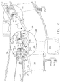
FIG. 2 is an enlarged view of a turbine section of the engine shown inFIG. 1 ; -
FIG. 3 is a cross-sectional view of a portion ofFIG. 2 , showing the installation of axial pins in the turbine section; -
FIG. 4 is a partial front elevation view of a centering spring shown inFIG. 2 ; and -
FIG. 5 is top view of the centering spring ofFIG. 4 ; and -
FIG. 6 is an enlarged view of a portion ofFIG. 2 , showing the installation of radial pins in the turbine section. - Referring to the drawings wherein identical reference numerals denote the same elements throughout the various views,
FIG. 1 depicts schematically the elements of an exemplarygas turbine engine 10 having acompressor 12, acombustor 14, and a high pressure or gas generator turbine ("GGT") 16, all arranged in a serial flow relationship along a centerline axis "A". As used herein, the terms "axial" or "longitudinal" refer to a direction parallel to the axis A, while the term "radial" refers to a direction perpendicular to the axis A. Collectively thecompressor 12, thecombustor 14, and the GGT 16 are referred to as a "core". Thecompressor 12 provides compressed air that passes into thecombustor 14 where fuel is introduced and burned, generating hot combustion gases. The hot combustion gases are discharged to the GGT 16 where they are expanded to extract energy therefrom. The GGT 16 drives thecompressor 12 through ashaft 18. Pressurized air exiting from the GGT 16 is discharged to a low pressure turbine or power turbine ("LPT") 20 where it is further expanded to extract energy. Thepower turbine 20 is coupled to an external mechanical load such as a shaft, gearbox, or propeller (depicted schematically atblock 21 inFIG. 1 ). - While the illustrated
engine 10 is a turboshaft engine, the principles described herein are equally applicable to turbojet and turbofan engines, as well as turbine engines used for other vehicles or in stationary applications. Furthermore, while a GGT shroud structure is used as an example, it will be understood that the principles of the present invention may be applied to any turbine airfoil having shrouds, including without limitation high-pressure turbine ("HPT") and intermediate-pressure turbine ("IPT") blades. Furthermore, the principles described herein are also applicable to turbines using working fluids other than air, such as steam turbines. - Referring to
FIG. 2 , the GGT 16 includes a nozzle comprising a plurality of circumferentially spaced airfoil-shapedhollow vanes 28, and a rotor comprising a rotatingdisk 30 that carries an array of airfoil-shaped turbine blades 32. In this example thevanes 28,disk 30, andturbine blades 32 comprise the second of two axial stages in theGGT 16; however the principles of the present invention are equally applicable to single-stage turbines or any stage of a multiple-stage turbine. - The
vanes 28 are bounded at their tips by an annularouter band 34. An annularforward rail 36 with a forward-facing L-shaped cross-section extends radially outward from a forward end of theouter band 34, and anannular aft rail 38 with an aft-facing L-shaped cross-section extends radially outward from an aft end of theouter band 34. - The
vanes 28 are surrounded by and mounted to a stationary,annular shroud support 40. The aft portion of theshroud support 40 includes, in axial sequence beginning at its aft end and proceeding forward, anannular boss 42 with a radially-extending retaining ring groove 44 formed in its inner surface, an annular, aft-facinghanger groove 46, and anannular slot 48 which receives theaft rail 38 of thevane 28. - An
annular hanger 50 abuts the aft end of theaft rail 38. Thehanger 50 includes a forward-facinghook 52 which engages thehanger groove 46. Thus assembled, thehanger 50 clamps theaft rail 38 to theshroud support 40 in the radial direction. - An annular retaining ring 54 with an L-shaped cross-section is installed against the inner surface of the
shroud support 40, with one leg of the "L" in the retaining ring groove 44. The retaining ring 54 extends radially inward sufficiently far to overlap thehanger 50 in the radial direction and abut thehanger 50, thereby preventing the hanger from moving aft and disengaging thehanger groove 46. - A resilient,
annular retainer 47 having a C-shaped cross-section, commonly referred to as a "C-clip", is mounted over theboss 42 of theshroud support 40 and the retaining ring 54, clamping them together. - The above-noted components may all be constructed of known metallic alloys suitable for use in gas turbine engines, for example known nickel-, cobalt-, or iron-based superalloys. Such alloys are available commercially under trade names such as RENE, INCO, and WASPALLOY.
- An
annular flowpath member 56 surrounds theturbine blades 32. It serves the functions of both a conventional turbine shroud and a conventional outer transition duct. Theflowpath member 56 has aflowpath surface 58 and opposedback surface 60 and includes, from front to rear, a generally cylindricalforward section 62 and an aft section 64 that extends aft and radially outward at a non-perpendicular, non-parallel angle to the axis A. Theforward section 62 surrounds theturbine blades 32 and defines part of the flowpath through the blades. Anannular aft flange 65 extends radially outward at the aft end of theflowpath member 56. The forward end of theflowpath member 56 abuts thehanger 50 and theaft flange 65 abuts thedownstream nozzle 66 of thepower turbine 20. Collectively these locate theflowpath member 56 in the axial direction. - The
flowpath member 56 is mounted so that it can expand or contract in diameter (e.g. radial compliance) while being restrained against rotation relative to theturbine case 78 that surrounds it. Various types of mechanical structures may be used to provide this restraint. One configuration is seen inFIG. 3 , whereaxial pins 68 fixed in theturbine case 78 extend aft intoradial slots 69 formed in theaft flange 65 of the flowpathmember 56. When at least three equally-spacedaxial pins 68 are used, theflowpath member 56 is also completely restrained against lateral deflection, i.e. held concentric to theturbine case 78. - The
flowpath member 56 is constructed from a ceramic matrix composite (CMC) material of a known type. Generally, commercially available CMC materials include a ceramic type fiber for example SiC, forms of which are coated with a compliant material such as Boron Nitride (BN). The fibers are carried in a ceramic type matrix, one form of which is Silicon Carbide (SiC). Typically, CMC type materials have a room temperature tensile ductility of no greater than about 1%, herein used to define and mean a low tensile ductility material. Generally CMC type materials have a room temperature tensile ductility in the range of about 0.4 to about 0.7%. This is compared with metals having a room temperature tensile ductility of at least about 5%, for example in the range of about 5 to about 15%. Theflowpath member 56 could also be constructed from other low-ductility, high-temperature-capable materials. - Optionally, all or part of the
flowpath surface 58 may incorporate a layer of an environmental coating, or an abradable or rub-tolerant material of a known type suitable for use with CMC materials. - Referring back to
FIG. 2 , theflowpath member 56 is located in the radial direction by a metallic, annular centeringspring 70. The centeringspring 70 has a generally frustoconical shape with its smaller diameter at its forward end and a radially-outwardly-extending, L-shapedflange 71 at its aft end. As best seen inFIGS. 4 and 5 , the forward portion of the centeringspring 70 is divided byslots 72 into an array ofresilient spring fingers 74. The centeringspring 70 is trapped between anannular rim 76 which is part of theturbine case 78, and theflowpath member 56 itself. In the installed position, thespring fingers 74 bear against theflowpath member 56. Eachindividual spring finger 74 urges theflowpath member 56 radially inward, with the complete ring ofspring fingers 74 keeping theflowpath member 56 in a centered position. The characteristics of the centeringspring 70, such as the material, temper, dimensions, etc. may be varied as required to provide a desired preload or centering force on theflowpath member 56. - An array of
spring tabs 80 extend axially forward and radially outward from the body of the centeringspring 70. Eachspring tab 80 has a radially-alignedflange 82 which bears against the C-clip 47 in an axial direction. The centeringspring 70 reacts axially against therim 76 of theturbine case 78, so thespring tabs 80 serve to urge the C-clip 47 forward and prevent it from backing off from its installed position. - The centering
spring 70 is fixed against rotation relative to theturbine case 78. In the illustrated example, tack welds 79 are applied between theflange 71 and theannular rim 76 of theturbine case 78. Alternate means of preventing rotation such as a mechanical joint or mechanical fasteners may be used instead. - An alternative method of restraining the flowpath member according to the invention is seen in
FIG. 6 . Radial pins 84 are received inslots 86 machined in theflowpath member 56. Thepins 84 extend through holes in the centeringspring 70 and are fixed thereto, for example by tack welds. The radial pins 84 allow for differential thermal growth between theflowpath member 56 and the centeringspring 70, but prevent transverse shroud movements during maneuvers or heavy rubs, and also prevent relative rotation of the flowpathmember 56 to the centeringspring 70, and thus theturbine case 78. When at least three equally-spaced radial pins 84 are used, theflowpath member 56 is completely restrained against lateral deflection, i.e. held concentric to theturbine case 78. - Resilient annular metallic seals having convoluted cross-sections, commonly referred to as "W-seals", may be provided to prevent air leakage between the
flowpath member 56 and the surrounding structure. Examples of W-seals are shown asitems FIG. 2 . - The shroud configuration described herein has several advantages over conventional configurations. The
flowpath member 56 provides a flowpath surface that can operate without air cooling, providing cycle performance benefits. Furthermore, there are no sectors, as the part is an axisymmetric, mechanically-trapped structure. This provides weight reduction benefits, as does the elimination of a separate shroud and duct structure. It also is expected that thermal stress in the flowpath member will be low due to the low thermal expansion coefficient of the CMC material.
Claims (10)
- A turbine flowpath apparatus for a gas turbine engine having a centerline axis, the apparatus comprising:an annular flowpath member (56) comprising ceramic matrix composite material, the flowpath member (56) having a flowpath surface (58) and an opposed back surface (60), and having a cross-sectional shape comprising a generally cylindrical forward section (62) and an aft section (64) that extends aft and radially outward at a non-perpendicular, non-parallel angle to the centerline axis;an annular stationary structure (78) surrounding the flowpath member (56); andan annular centering spring (70) disposed between the stationary structure (78) and the flowpath member (56), the centering spring (70) urging the flowpath member (56) towards a centered position within the stationary structure (78);characterized in that:
the apparatus further includes radial pins (84) fixed to the centering spring (70) and extending into corresponding slots (86) formed in the back surface of the flowpath member (56), so as to prevent relative lateral movement and relative rotation of the flowpath member (56) and the centering spring (70). - The apparatus of claim 1, the apparatus further comprising:an annular shroud support (40);an annular shroud hanger (50) engaged with the shroud support (40);wherein a forward end of the flowpath member (56) abuts the shroud hanger (50);the annular stationary structure (78) comprising an annular turbine case (78), the annular turbine case (78) surrounding the flowpath member (56) and the shroud support; andthe annular centering spring (70) disposed between the turbine case (78) and the flowpath member (56), the centering spring (70) urging the flowpath member (56) towards a centered position within the turbine case (78).
- The apparatus of any preceding claim, wherein the centering spring (70) has a generally frustoconical shape with a radially-outwardly-extending, L-shaped flange (71) at one axial end.
- The apparatus of any preceding claim, wherein the centering spring (70) includes an annular array of resilient spring fingers (74) separated by generally axially-aligned slots (72).
- The apparatus of claim 2, further comprising:a retaining ring (54) engaging a groove in the shroud support (40) and axially abutting the hanger (50); anda resilient, annular retainer (47) having a C-shaped cross-section clamping the shroud support (40) and the retaining ring (54) together.
- The apparatus of claim 5, wherein the centering spring (70) includes spring tabs (80) which abut the annular retainer (47), such that the centering spring (70) urges the retainer (47) axially against the shroud support (40).
- The apparatus of claim 2, wherein the flowpath member (56) includes an aft flange (65) which extends radially outward from an aft end thereof, the aft flange (65) abutting an axially downstream turbine nozzle (66).
- The apparatus of claim 7, further including axial pins (68) fixed to the turbine case (78) and extending into corresponding slots (69) formed in the aft flange of the flowpath member (56), so as to prevent relative lateral movement of the flowpath member (56) and the turbine case (78).
- The apparatus of claim 2, further including a rotor comprising a rotatable disk (30) that carries an array of airfoil-shaped turbine blades (32), wherein the forward section (62) of the flowpath member (56) surrounds the turbine blades (32) and defines a portion of a flowpath through the turbine blades (32).
- The apparatus of claim 1, further including axial pins (68) fixed to the stationary structure (78) and extending into corresponding slots (69) formed in a flange (65) of the flowpath member (56), so as to prevent relative lateral movement and relative rotation of the flowpath member (56) and the stationary structure (78).
Applications Claiming Priority (1)
| Application Number | Priority Date | Filing Date | Title |
|---|---|---|---|
| US12/971,893 US8926270B2 (en) | 2010-12-17 | 2010-12-17 | Low-ductility turbine shroud flowpath and mounting arrangement therefor |
Publications (3)
| Publication Number | Publication Date |
|---|---|
| EP2466073A2 EP2466073A2 (en) | 2012-06-20 |
| EP2466073A3 EP2466073A3 (en) | 2018-01-03 |
| EP2466073B1 true EP2466073B1 (en) | 2019-05-29 |
Family
ID=45098930
Family Applications (1)
| Application Number | Title | Priority Date | Filing Date |
|---|---|---|---|
| EP11191604.5A Active EP2466073B1 (en) | 2010-12-17 | 2011-12-01 | Low-ductility turbine flowpath apparatus |
Country Status (4)
| Country | Link |
|---|---|
| US (1) | US8926270B2 (en) |
| EP (1) | EP2466073B1 (en) |
| JP (1) | JP5981710B2 (en) |
| CA (1) | CA2760035C (en) |
Families Citing this family (60)
| Publication number | Priority date | Publication date | Assignee | Title |
|---|---|---|---|---|
| US9726043B2 (en) | 2011-12-15 | 2017-08-08 | General Electric Company | Mounting apparatus for low-ductility turbine shroud |
| WO2014120334A1 (en) | 2013-01-29 | 2014-08-07 | Sippel Aaron D | Turbine shroud |
| US10612407B2 (en) | 2013-02-28 | 2020-04-07 | United Technologies Corporation | Contoured blade outer air seal for a gas turbine engine |
| EP2964899B1 (en) | 2013-03-05 | 2018-12-05 | Rolls-Royce Corporation | Structure and method for providing compliance and sealing between ceramic and metallic structures |
| CA2897965C (en) | 2013-03-11 | 2020-02-25 | David J. Thomas | Compliant intermediate component of a gas turbine engine |
| EP2971587B1 (en) | 2013-03-12 | 2020-02-05 | Rolls-Royce Corporation | Turbine blade track assembly |
| EP2971588A1 (en) | 2013-03-13 | 2016-01-20 | Rolls-Royce Corporation | Dovetail retention system for blade tracks |
| US10094233B2 (en) | 2013-03-13 | 2018-10-09 | Rolls-Royce Corporation | Turbine shroud |
| JP6114878B2 (en) | 2013-05-17 | 2017-04-12 | ゼネラル・エレクトリック・カンパニイ | CMC shroud support system |
| CA2917765C (en) | 2013-07-19 | 2020-09-15 | General Electric Company | Turbine nozzle with impingement baffle |
| ES2935815T3 (en) * | 2013-09-06 | 2023-03-10 | MTU Aero Engines AG | (Dis)assembly of a gas turbine rotor, in particular front |
| US10801411B2 (en) | 2013-09-11 | 2020-10-13 | Raytheon Technologies Corporation | Ceramic liner for a turbine exhaust case |
| US9598981B2 (en) * | 2013-11-22 | 2017-03-21 | Siemens Energy, Inc. | Industrial gas turbine exhaust system diffuser inlet lip |
| WO2015088869A1 (en) | 2013-12-12 | 2015-06-18 | General Electric Company | Cmc shroud support system |
| FR3016391B1 (en) * | 2014-01-10 | 2017-12-29 | Snecma | DEVICE FOR SEALING AND THERMALLY PROTECTING A TURBOMACHINE |
| CN106460543B (en) | 2014-06-12 | 2018-12-21 | 通用电气公司 | Multi-piece type shield hangs device assembly |
| CN106460542B (en) | 2014-06-12 | 2018-11-02 | 通用电气公司 | Shield hanger component |
| CA2951425C (en) | 2014-06-12 | 2019-12-24 | General Electric Company | Shroud hanger assembly |
| US9957827B2 (en) * | 2014-10-24 | 2018-05-01 | United Technologies Corporation | Conformal seal |
| US10190434B2 (en) | 2014-10-29 | 2019-01-29 | Rolls-Royce North American Technologies Inc. | Turbine shroud with locating inserts |
| EP3034803A1 (en) | 2014-12-16 | 2016-06-22 | Rolls-Royce Corporation | Hanger system for a turbine engine component |
| US20160169038A1 (en) * | 2014-12-16 | 2016-06-16 | Rolls-Royce Corporation | Cooling feature for a turbine engine component |
| CA2915246A1 (en) | 2014-12-23 | 2016-06-23 | Rolls-Royce Corporation | Turbine shroud |
| CA2915370A1 (en) | 2014-12-23 | 2016-06-23 | Rolls-Royce Corporation | Full hoop blade track with axially keyed features |
| EP3045674B1 (en) | 2015-01-15 | 2018-11-21 | Rolls-Royce Corporation | Turbine shroud with tubular runner-locating inserts |
| US10934871B2 (en) | 2015-02-20 | 2021-03-02 | Rolls-Royce North American Technologies Inc. | Segmented turbine shroud with sealing features |
| US9874104B2 (en) | 2015-02-27 | 2018-01-23 | General Electric Company | Method and system for a ceramic matrix composite shroud hanger assembly |
| US10309257B2 (en) | 2015-03-02 | 2019-06-04 | Rolls-Royce North American Technologies Inc. | Turbine assembly with load pads |
| US9587502B2 (en) * | 2015-03-06 | 2017-03-07 | United Technologies Corporation | Sliding compliant seal |
| US10260364B2 (en) * | 2015-03-09 | 2019-04-16 | United Technologies Corporation | Sliding seal |
| CA2924855A1 (en) | 2015-04-29 | 2016-10-29 | Rolls-Royce Corporation | Keystoned blade track |
| CA2925588A1 (en) | 2015-04-29 | 2016-10-29 | Rolls-Royce Corporation | Brazed blade track for a gas turbine engine |
| US10550709B2 (en) | 2015-04-30 | 2020-02-04 | Rolls-Royce North American Technologies Inc. | Full hoop blade track with flanged segments |
| US10087770B2 (en) | 2015-05-26 | 2018-10-02 | Rolls-Royce Corporation | Shroud cartridge having a ceramic matrix composite seal segment |
| US10370997B2 (en) | 2015-05-26 | 2019-08-06 | Rolls-Royce Corporation | Turbine shroud having ceramic matrix composite seal segment |
| US10370998B2 (en) | 2015-05-26 | 2019-08-06 | Rolls-Royce Corporation | Flexibly mounted ceramic matrix composite seal segments |
| US9963990B2 (en) | 2015-05-26 | 2018-05-08 | Rolls-Royce North American Technologies, Inc. | Ceramic matrix composite seal segment for a gas turbine engine |
| US10221713B2 (en) | 2015-05-26 | 2019-03-05 | Rolls-Royce Corporation | Shroud cartridge having a ceramic matrix composite seal segment |
| EP3109043B1 (en) | 2015-06-22 | 2018-01-31 | Rolls-Royce Corporation | Method for integral joining infiltrated ceramic matrix composites |
| US10385718B2 (en) | 2015-06-29 | 2019-08-20 | Rolls-Royce North American Technologies, Inc. | Turbine shroud segment with side perimeter seal |
| US10184352B2 (en) | 2015-06-29 | 2019-01-22 | Rolls-Royce North American Technologies Inc. | Turbine shroud segment with integrated cooling air distribution system |
| US10196919B2 (en) | 2015-06-29 | 2019-02-05 | Rolls-Royce North American Technologies Inc. | Turbine shroud segment with load distribution springs |
| US10094234B2 (en) | 2015-06-29 | 2018-10-09 | Rolls-Royce North America Technologies Inc. | Turbine shroud segment with buffer air seal system |
| US10047624B2 (en) | 2015-06-29 | 2018-08-14 | Rolls-Royce North American Technologies Inc. | Turbine shroud segment with flange-facing perimeter seal |
| US10036269B2 (en) * | 2015-10-23 | 2018-07-31 | General Electric Company | Leaf seal reach over spring with retention mechanism |
| US20170198602A1 (en) * | 2016-01-11 | 2017-07-13 | General Electric Company | Gas turbine engine with a cooled nozzle segment |
| US10240476B2 (en) | 2016-01-19 | 2019-03-26 | Rolls-Royce North American Technologies Inc. | Full hoop blade track with interstage cooling air |
| US10247040B2 (en) | 2016-01-19 | 2019-04-02 | Rolls-Royce North American Technologies Inc. | Turbine shroud with mounted full hoop blade track |
| US10480342B2 (en) | 2016-01-19 | 2019-11-19 | Rolls-Royce Corporation | Gas turbine engine with health monitoring system |
| US11193392B2 (en) * | 2016-03-21 | 2021-12-07 | General Electric Company | CMC ply overlap ingestion restrictor |
| US10458268B2 (en) | 2016-04-13 | 2019-10-29 | Rolls-Royce North American Technologies Inc. | Turbine shroud with sealed box segments |
| US10415415B2 (en) | 2016-07-22 | 2019-09-17 | Rolls-Royce North American Technologies Inc. | Turbine shroud with forward case and full hoop blade track |
| US10287906B2 (en) | 2016-05-24 | 2019-05-14 | Rolls-Royce North American Technologies Inc. | Turbine shroud with full hoop ceramic matrix composite blade track and seal system |
| FR3056637B1 (en) * | 2016-09-27 | 2018-10-19 | Safran Aircraft Engines | TURBINE RING ASSEMBLY WITH COLD SETTING |
| US10544793B2 (en) | 2017-01-25 | 2020-01-28 | General Electric Company | Thermal isolation structure for rotating turbine frame |
| US10480337B2 (en) | 2017-04-18 | 2019-11-19 | Rolls-Royce North American Technologies Inc. | Turbine shroud assembly with multi-piece seals |
| US10533446B2 (en) * | 2017-05-15 | 2020-01-14 | United Technologies Corporation | Alternative W-seal groove arrangement |
| CA3000376A1 (en) * | 2017-05-23 | 2018-11-23 | Rolls-Royce Corporation | Turbine shroud assembly having ceramic matrix composite track segments with metallic attachment features |
| US11015485B2 (en) | 2019-04-17 | 2021-05-25 | Rolls-Royce Corporation | Seal ring for turbine shroud in gas turbine engine with arch-style support |
| US11428160B2 (en) | 2020-12-31 | 2022-08-30 | General Electric Company | Gas turbine engine with interdigitated turbine and gear assembly |
Family Cites Families (22)
| Publication number | Priority date | Publication date | Assignee | Title |
|---|---|---|---|---|
| US3825364A (en) * | 1972-06-09 | 1974-07-23 | Gen Electric | Porous abradable turbine shroud |
| US4087199A (en) * | 1976-11-22 | 1978-05-02 | General Electric Company | Ceramic turbine shroud assembly |
| GB2239678B (en) * | 1989-12-08 | 1993-03-03 | Rolls Royce Plc | Gas turbine engine blade shroud assembly |
| US5064727A (en) | 1990-01-19 | 1991-11-12 | Avco Corporation | Abradable hybrid ceramic wall structures |
| US5074748A (en) | 1990-07-30 | 1991-12-24 | General Electric Company | Seal assembly for segmented turbine engine structures |
| US5154577A (en) | 1991-01-17 | 1992-10-13 | General Electric Company | Flexible three-piece seal assembly |
| US5188507A (en) * | 1991-11-27 | 1993-02-23 | General Electric Company | Low-pressure turbine shroud |
| US5927942A (en) * | 1993-10-27 | 1999-07-27 | United Technologies Corporation | Mounting and sealing arrangement for a turbine shroud segment |
| US5655876A (en) | 1996-01-02 | 1997-08-12 | General Electric Company | Low leakage turbine nozzle |
| JP2957943B2 (en) * | 1996-02-26 | 1999-10-06 | 川崎重工業株式会社 | Turbine with ceramic shroud |
| DE19850732A1 (en) * | 1998-11-04 | 2000-05-11 | Asea Brown Boveri | Axial turbine |
| US6290459B1 (en) | 1999-11-01 | 2001-09-18 | General Electric Company | Stationary flowpath components for gas turbine engines |
| US6340285B1 (en) | 2000-06-08 | 2002-01-22 | General Electric Company | End rail cooling for combined high and low pressure turbine shroud |
| EP1243756A1 (en) * | 2001-03-23 | 2002-09-25 | Siemens Aktiengesellschaft | Turbine |
| US6503051B2 (en) | 2001-06-06 | 2003-01-07 | General Electric Company | Overlapping interference seal and methods for forming the seal |
| US6733233B2 (en) | 2002-04-26 | 2004-05-11 | Pratt & Whitney Canada Corp. | Attachment of a ceramic shroud in a metal housing |
| US6726448B2 (en) | 2002-05-15 | 2004-04-27 | General Electric Company | Ceramic turbine shroud |
| US7596954B2 (en) * | 2004-07-09 | 2009-10-06 | United Technologies Corporation | Blade clearance control |
| US7438520B2 (en) * | 2005-08-06 | 2008-10-21 | General Electric Company | Thermally compliant turbine shroud mounting assembly |
| GB0703827D0 (en) | 2007-02-28 | 2007-04-11 | Rolls Royce Plc | Rotor seal segment |
| US8047773B2 (en) * | 2007-08-23 | 2011-11-01 | General Electric Company | Gas turbine shroud support apparatus |
| FR2938872B1 (en) * | 2008-11-26 | 2015-11-27 | Snecma | ANTI-WEAR DEVICE FOR AUBES OF A TURBINE DISPENSER OF AERONAUTICAL TURBOMACHINE |
-
2010
- 2010-12-17 US US12/971,893 patent/US8926270B2/en active Active
-
2011
- 2011-12-01 CA CA2760035A patent/CA2760035C/en active Active
- 2011-12-01 EP EP11191604.5A patent/EP2466073B1/en active Active
- 2011-12-16 JP JP2011275136A patent/JP5981710B2/en active Active
Non-Patent Citations (1)
| Title |
|---|
| None * |
Also Published As
| Publication number | Publication date |
|---|---|
| JP2012132444A (en) | 2012-07-12 |
| CA2760035C (en) | 2019-04-30 |
| EP2466073A3 (en) | 2018-01-03 |
| US20120156029A1 (en) | 2012-06-21 |
| JP5981710B2 (en) | 2016-08-31 |
| EP2466073A2 (en) | 2012-06-20 |
| CA2760035A1 (en) | 2012-06-17 |
| US8926270B2 (en) | 2015-01-06 |
Similar Documents
| Publication | Publication Date | Title |
|---|---|---|
| EP2466073B1 (en) | Low-ductility turbine flowpath apparatus | |
| EP3091187B1 (en) | Turbine component assembly with thermally stress-free fastener | |
| EP2357322B1 (en) | Mounting apparatus for low-ductility turbine shroud | |
| CA2740538C (en) | Low-ductility turbine shroud and mounting apparatus | |
| US8579580B2 (en) | Mounting apparatus for low-ductility turbine shroud | |
| US8998573B2 (en) | Resilient mounting apparatus for low-ductility turbine shroud | |
| EP2540994B1 (en) | Chordal mounting arrangement for low-ductility turbine shroud | |
| US8905709B2 (en) | Low-ductility open channel turbine shroud | |
| US20140212284A1 (en) | Hybrid turbine nozzle | |
| EP3351740B1 (en) | Section of a gas turbine comprising a segmented blade outer air seal | |
| WO2015002673A2 (en) | Gas turbine engine seal assembly | |
| EP3030752A1 (en) | Mounting apparatus for low-ductility turbine nozzle |
Legal Events
| Date | Code | Title | Description |
|---|---|---|---|
| PUAI | Public reference made under article 153(3) epc to a published international application that has entered the european phase |
Free format text: ORIGINAL CODE: 0009012 |
|
| AK | Designated contracting states |
Kind code of ref document: A2 Designated state(s): AL AT BE BG CH CY CZ DE DK EE ES FI FR GB GR HR HU IE IS IT LI LT LU LV MC MK MT NL NO PL PT RO RS SE SI SK SM TR |
|
| AX | Request for extension of the european patent |
Extension state: BA ME |
|
| PUAL | Search report despatched |
Free format text: ORIGINAL CODE: 0009013 |
|
| AK | Designated contracting states |
Kind code of ref document: A3 Designated state(s): AL AT BE BG CH CY CZ DE DK EE ES FI FR GB GR HR HU IE IS IT LI LT LU LV MC MK MT NL NO PL PT RO RS SE SI SK SM TR |
|
| AX | Request for extension of the european patent |
Extension state: BA ME |
|
| RIC1 | Information provided on ipc code assigned before grant |
Ipc: F01D 11/08 20060101AFI20171129BHEP Ipc: F01D 25/24 20060101ALI20171129BHEP Ipc: F01D 9/04 20060101ALI20171129BHEP |
|
| STAA | Information on the status of an ep patent application or granted ep patent |
Free format text: STATUS: REQUEST FOR EXAMINATION WAS MADE |
|
| 17P | Request for examination filed |
Effective date: 20180703 |
|
| RBV | Designated contracting states (corrected) |
Designated state(s): AL AT BE BG CH CY CZ DE DK EE ES FI FR GB GR HR HU IE IS IT LI LT LU LV MC MK MT NL NO PL PT RO RS SE SI SK SM TR |
|
| REG | Reference to a national code |
Ref country code: DE Ref legal event code: R079 Ref document number: 602011059328 Country of ref document: DE Free format text: PREVIOUS MAIN CLASS: F01D0009020000 Ipc: F01D0011080000 |
|
| RIC1 | Information provided on ipc code assigned before grant |
Ipc: F01D 25/24 20060101ALI20181219BHEP Ipc: F01D 11/08 20060101AFI20181219BHEP |
|
| GRAP | Despatch of communication of intention to grant a patent |
Free format text: ORIGINAL CODE: EPIDOSNIGR1 |
|
| STAA | Information on the status of an ep patent application or granted ep patent |
Free format text: STATUS: GRANT OF PATENT IS INTENDED |
|
| INTG | Intention to grant announced |
Effective date: 20190129 |
|
| GRAS | Grant fee paid |
Free format text: ORIGINAL CODE: EPIDOSNIGR3 |
|
| GRAA | (expected) grant |
Free format text: ORIGINAL CODE: 0009210 |
|
| STAA | Information on the status of an ep patent application or granted ep patent |
Free format text: STATUS: THE PATENT HAS BEEN GRANTED |
|
| AK | Designated contracting states |
Kind code of ref document: B1 Designated state(s): AL AT BE BG CH CY CZ DE DK EE ES FI FR GB GR HR HU IE IS IT LI LT LU LV MC MK MT NL NO PL PT RO RS SE SI SK SM TR |
|
| REG | Reference to a national code |
Ref country code: GB Ref legal event code: FG4D |
|
| REG | Reference to a national code |
Ref country code: CH Ref legal event code: EP |
|
| REG | Reference to a national code |
Ref country code: DE Ref legal event code: R096 Ref document number: 602011059328 Country of ref document: DE |
|
| REG | Reference to a national code |
Ref country code: AT Ref legal event code: REF Ref document number: 1138378 Country of ref document: AT Kind code of ref document: T Effective date: 20190615 |
|
| REG | Reference to a national code |
Ref country code: IE Ref legal event code: FG4D |
|
| REG | Reference to a national code |
Ref country code: NL Ref legal event code: MP Effective date: 20190529 |
|
| REG | Reference to a national code |
Ref country code: LT Ref legal event code: MG4D |
|
| PG25 | Lapsed in a contracting state [announced via postgrant information from national office to epo] |
Ref country code: FI Free format text: LAPSE BECAUSE OF FAILURE TO SUBMIT A TRANSLATION OF THE DESCRIPTION OR TO PAY THE FEE WITHIN THE PRESCRIBED TIME-LIMIT Effective date: 20190529 Ref country code: LT Free format text: LAPSE BECAUSE OF FAILURE TO SUBMIT A TRANSLATION OF THE DESCRIPTION OR TO PAY THE FEE WITHIN THE PRESCRIBED TIME-LIMIT Effective date: 20190529 Ref country code: AL Free format text: LAPSE BECAUSE OF FAILURE TO SUBMIT A TRANSLATION OF THE DESCRIPTION OR TO PAY THE FEE WITHIN THE PRESCRIBED TIME-LIMIT Effective date: 20190529 Ref country code: ES Free format text: LAPSE BECAUSE OF FAILURE TO SUBMIT A TRANSLATION OF THE DESCRIPTION OR TO PAY THE FEE WITHIN THE PRESCRIBED TIME-LIMIT Effective date: 20190529 Ref country code: PT Free format text: LAPSE BECAUSE OF FAILURE TO SUBMIT A TRANSLATION OF THE DESCRIPTION OR TO PAY THE FEE WITHIN THE PRESCRIBED TIME-LIMIT Effective date: 20190930 Ref country code: SE Free format text: LAPSE BECAUSE OF FAILURE TO SUBMIT A TRANSLATION OF THE DESCRIPTION OR TO PAY THE FEE WITHIN THE PRESCRIBED TIME-LIMIT Effective date: 20190529 Ref country code: NO Free format text: LAPSE BECAUSE OF FAILURE TO SUBMIT A TRANSLATION OF THE DESCRIPTION OR TO PAY THE FEE WITHIN THE PRESCRIBED TIME-LIMIT Effective date: 20190829 Ref country code: HR Free format text: LAPSE BECAUSE OF FAILURE TO SUBMIT A TRANSLATION OF THE DESCRIPTION OR TO PAY THE FEE WITHIN THE PRESCRIBED TIME-LIMIT Effective date: 20190529 |
|
| PG25 | Lapsed in a contracting state [announced via postgrant information from national office to epo] |
Ref country code: LV Free format text: LAPSE BECAUSE OF FAILURE TO SUBMIT A TRANSLATION OF THE DESCRIPTION OR TO PAY THE FEE WITHIN THE PRESCRIBED TIME-LIMIT Effective date: 20190529 Ref country code: GR Free format text: LAPSE BECAUSE OF FAILURE TO SUBMIT A TRANSLATION OF THE DESCRIPTION OR TO PAY THE FEE WITHIN THE PRESCRIBED TIME-LIMIT Effective date: 20190830 Ref country code: BG Free format text: LAPSE BECAUSE OF FAILURE TO SUBMIT A TRANSLATION OF THE DESCRIPTION OR TO PAY THE FEE WITHIN THE PRESCRIBED TIME-LIMIT Effective date: 20190829 Ref country code: RS Free format text: LAPSE BECAUSE OF FAILURE TO SUBMIT A TRANSLATION OF THE DESCRIPTION OR TO PAY THE FEE WITHIN THE PRESCRIBED TIME-LIMIT Effective date: 20190529 |
|
| REG | Reference to a national code |
Ref country code: AT Ref legal event code: MK05 Ref document number: 1138378 Country of ref document: AT Kind code of ref document: T Effective date: 20190529 |
|
| PG25 | Lapsed in a contracting state [announced via postgrant information from national office to epo] |
Ref country code: SK Free format text: LAPSE BECAUSE OF FAILURE TO SUBMIT A TRANSLATION OF THE DESCRIPTION OR TO PAY THE FEE WITHIN THE PRESCRIBED TIME-LIMIT Effective date: 20190529 Ref country code: EE Free format text: LAPSE BECAUSE OF FAILURE TO SUBMIT A TRANSLATION OF THE DESCRIPTION OR TO PAY THE FEE WITHIN THE PRESCRIBED TIME-LIMIT Effective date: 20190529 Ref country code: CZ Free format text: LAPSE BECAUSE OF FAILURE TO SUBMIT A TRANSLATION OF THE DESCRIPTION OR TO PAY THE FEE WITHIN THE PRESCRIBED TIME-LIMIT Effective date: 20190529 Ref country code: NL Free format text: LAPSE BECAUSE OF FAILURE TO SUBMIT A TRANSLATION OF THE DESCRIPTION OR TO PAY THE FEE WITHIN THE PRESCRIBED TIME-LIMIT Effective date: 20190529 Ref country code: RO Free format text: LAPSE BECAUSE OF FAILURE TO SUBMIT A TRANSLATION OF THE DESCRIPTION OR TO PAY THE FEE WITHIN THE PRESCRIBED TIME-LIMIT Effective date: 20190529 Ref country code: AT Free format text: LAPSE BECAUSE OF FAILURE TO SUBMIT A TRANSLATION OF THE DESCRIPTION OR TO PAY THE FEE WITHIN THE PRESCRIBED TIME-LIMIT Effective date: 20190529 Ref country code: DK Free format text: LAPSE BECAUSE OF FAILURE TO SUBMIT A TRANSLATION OF THE DESCRIPTION OR TO PAY THE FEE WITHIN THE PRESCRIBED TIME-LIMIT Effective date: 20190529 |
|
| PG25 | Lapsed in a contracting state [announced via postgrant information from national office to epo] |
Ref country code: SM Free format text: LAPSE BECAUSE OF FAILURE TO SUBMIT A TRANSLATION OF THE DESCRIPTION OR TO PAY THE FEE WITHIN THE PRESCRIBED TIME-LIMIT Effective date: 20190529 Ref country code: IT Free format text: LAPSE BECAUSE OF FAILURE TO SUBMIT A TRANSLATION OF THE DESCRIPTION OR TO PAY THE FEE WITHIN THE PRESCRIBED TIME-LIMIT Effective date: 20190529 |
|
| REG | Reference to a national code |
Ref country code: DE Ref legal event code: R097 Ref document number: 602011059328 Country of ref document: DE |
|
| PG25 | Lapsed in a contracting state [announced via postgrant information from national office to epo] |
Ref country code: TR Free format text: LAPSE BECAUSE OF FAILURE TO SUBMIT A TRANSLATION OF THE DESCRIPTION OR TO PAY THE FEE WITHIN THE PRESCRIBED TIME-LIMIT Effective date: 20190529 |
|
| PLBE | No opposition filed within time limit |
Free format text: ORIGINAL CODE: 0009261 |
|
| STAA | Information on the status of an ep patent application or granted ep patent |
Free format text: STATUS: NO OPPOSITION FILED WITHIN TIME LIMIT |
|
| PG25 | Lapsed in a contracting state [announced via postgrant information from national office to epo] |
Ref country code: PL Free format text: LAPSE BECAUSE OF FAILURE TO SUBMIT A TRANSLATION OF THE DESCRIPTION OR TO PAY THE FEE WITHIN THE PRESCRIBED TIME-LIMIT Effective date: 20190529 |
|
| 26N | No opposition filed |
Effective date: 20200303 |
|
| PG25 | Lapsed in a contracting state [announced via postgrant information from national office to epo] |
Ref country code: SI Free format text: LAPSE BECAUSE OF FAILURE TO SUBMIT A TRANSLATION OF THE DESCRIPTION OR TO PAY THE FEE WITHIN THE PRESCRIBED TIME-LIMIT Effective date: 20190529 |
|
| REG | Reference to a national code |
Ref country code: CH Ref legal event code: PL |
|
| REG | Reference to a national code |
Ref country code: BE Ref legal event code: MM Effective date: 20191231 |
|
| PG25 | Lapsed in a contracting state [announced via postgrant information from national office to epo] |
Ref country code: MC Free format text: LAPSE BECAUSE OF FAILURE TO SUBMIT A TRANSLATION OF THE DESCRIPTION OR TO PAY THE FEE WITHIN THE PRESCRIBED TIME-LIMIT Effective date: 20190529 |
|
| PG25 | Lapsed in a contracting state [announced via postgrant information from national office to epo] |
Ref country code: IE Free format text: LAPSE BECAUSE OF NON-PAYMENT OF DUE FEES Effective date: 20191201 Ref country code: LU Free format text: LAPSE BECAUSE OF NON-PAYMENT OF DUE FEES Effective date: 20191201 |
|
| PG25 | Lapsed in a contracting state [announced via postgrant information from national office to epo] |
Ref country code: LI Free format text: LAPSE BECAUSE OF NON-PAYMENT OF DUE FEES Effective date: 20191231 Ref country code: BE Free format text: LAPSE BECAUSE OF NON-PAYMENT OF DUE FEES Effective date: 20191231 Ref country code: CH Free format text: LAPSE BECAUSE OF NON-PAYMENT OF DUE FEES Effective date: 20191231 |
|
| PG25 | Lapsed in a contracting state [announced via postgrant information from national office to epo] |
Ref country code: CY Free format text: LAPSE BECAUSE OF FAILURE TO SUBMIT A TRANSLATION OF THE DESCRIPTION OR TO PAY THE FEE WITHIN THE PRESCRIBED TIME-LIMIT Effective date: 20190529 |
|
| PG25 | Lapsed in a contracting state [announced via postgrant information from national office to epo] |
Ref country code: IS Free format text: LAPSE BECAUSE OF FAILURE TO SUBMIT A TRANSLATION OF THE DESCRIPTION OR TO PAY THE FEE WITHIN THE PRESCRIBED TIME-LIMIT Effective date: 20190929 |
|
| PG25 | Lapsed in a contracting state [announced via postgrant information from national office to epo] |
Ref country code: MT Free format text: LAPSE BECAUSE OF FAILURE TO SUBMIT A TRANSLATION OF THE DESCRIPTION OR TO PAY THE FEE WITHIN THE PRESCRIBED TIME-LIMIT Effective date: 20190529 Ref country code: HU Free format text: LAPSE BECAUSE OF FAILURE TO SUBMIT A TRANSLATION OF THE DESCRIPTION OR TO PAY THE FEE WITHIN THE PRESCRIBED TIME-LIMIT; INVALID AB INITIO Effective date: 20111201 |
|
| PG25 | Lapsed in a contracting state [announced via postgrant information from national office to epo] |
Ref country code: MK Free format text: LAPSE BECAUSE OF FAILURE TO SUBMIT A TRANSLATION OF THE DESCRIPTION OR TO PAY THE FEE WITHIN THE PRESCRIBED TIME-LIMIT Effective date: 20190529 |
|
| P01 | Opt-out of the competence of the unified patent court (upc) registered |
Effective date: 20230411 |
|
| PGFP | Annual fee paid to national office [announced via postgrant information from national office to epo] |
Ref country code: GB Payment date: 20231121 Year of fee payment: 13 |
|
| PGFP | Annual fee paid to national office [announced via postgrant information from national office to epo] |
Ref country code: FR Payment date: 20231122 Year of fee payment: 13 Ref country code: DE Payment date: 20231121 Year of fee payment: 13 |