EP3109043B1 - Method for integral joining infiltrated ceramic matrix composites - Google Patents
Method for integral joining infiltrated ceramic matrix composites Download PDFInfo
- Publication number
- EP3109043B1 EP3109043B1 EP16172531.2A EP16172531A EP3109043B1 EP 3109043 B1 EP3109043 B1 EP 3109043B1 EP 16172531 A EP16172531 A EP 16172531A EP 3109043 B1 EP3109043 B1 EP 3109043B1
- Authority
- EP
- European Patent Office
- Prior art keywords
- subpart
- green body
- ceramic
- biscuit
- green
- Prior art date
- Legal status (The legal status is an assumption and is not a legal conclusion. Google has not performed a legal analysis and makes no representation as to the accuracy of the status listed.)
- Active
Links
Images


Classifications
-
- B—PERFORMING OPERATIONS; TRANSPORTING
- B32—LAYERED PRODUCTS
- B32B—LAYERED PRODUCTS, i.e. PRODUCTS BUILT-UP OF STRATA OF FLAT OR NON-FLAT, e.g. CELLULAR OR HONEYCOMB, FORM
- B32B18/00—Layered products essentially comprising ceramics, e.g. refractory products
-
- C—CHEMISTRY; METALLURGY
- C04—CEMENTS; CONCRETE; ARTIFICIAL STONE; CERAMICS; REFRACTORIES
- C04B—LIME, MAGNESIA; SLAG; CEMENTS; COMPOSITIONS THEREOF, e.g. MORTARS, CONCRETE OR LIKE BUILDING MATERIALS; ARTIFICIAL STONE; CERAMICS; REFRACTORIES; TREATMENT OF NATURAL STONE
- C04B35/00—Shaped ceramic products characterised by their composition; Ceramics compositions; Processing powders of inorganic compounds preparatory to the manufacturing of ceramic products
- C04B35/515—Shaped ceramic products characterised by their composition; Ceramics compositions; Processing powders of inorganic compounds preparatory to the manufacturing of ceramic products based on non-oxide ceramics
- C04B35/56—Shaped ceramic products characterised by their composition; Ceramics compositions; Processing powders of inorganic compounds preparatory to the manufacturing of ceramic products based on non-oxide ceramics based on carbides or oxycarbides
- C04B35/565—Shaped ceramic products characterised by their composition; Ceramics compositions; Processing powders of inorganic compounds preparatory to the manufacturing of ceramic products based on non-oxide ceramics based on carbides or oxycarbides based on silicon carbide
- C04B35/573—Shaped ceramic products characterised by their composition; Ceramics compositions; Processing powders of inorganic compounds preparatory to the manufacturing of ceramic products based on non-oxide ceramics based on carbides or oxycarbides based on silicon carbide obtained by reaction sintering or recrystallisation
-
- C—CHEMISTRY; METALLURGY
- C04—CEMENTS; CONCRETE; ARTIFICIAL STONE; CERAMICS; REFRACTORIES
- C04B—LIME, MAGNESIA; SLAG; CEMENTS; COMPOSITIONS THEREOF, e.g. MORTARS, CONCRETE OR LIKE BUILDING MATERIALS; ARTIFICIAL STONE; CERAMICS; REFRACTORIES; TREATMENT OF NATURAL STONE
- C04B35/00—Shaped ceramic products characterised by their composition; Ceramics compositions; Processing powders of inorganic compounds preparatory to the manufacturing of ceramic products
- C04B35/71—Ceramic products containing macroscopic reinforcing agents
- C04B35/78—Ceramic products containing macroscopic reinforcing agents containing non-metallic materials
- C04B35/80—Fibres, filaments, whiskers, platelets, or the like
-
- C—CHEMISTRY; METALLURGY
- C04—CEMENTS; CONCRETE; ARTIFICIAL STONE; CERAMICS; REFRACTORIES
- C04B—LIME, MAGNESIA; SLAG; CEMENTS; COMPOSITIONS THEREOF, e.g. MORTARS, CONCRETE OR LIKE BUILDING MATERIALS; ARTIFICIAL STONE; CERAMICS; REFRACTORIES; TREATMENT OF NATURAL STONE
- C04B37/00—Joining burned ceramic articles with other burned ceramic articles or other articles by heating
- C04B37/001—Joining burned ceramic articles with other burned ceramic articles or other articles by heating directly with other burned ceramic articles
-
- C—CHEMISTRY; METALLURGY
- C04—CEMENTS; CONCRETE; ARTIFICIAL STONE; CERAMICS; REFRACTORIES
- C04B—LIME, MAGNESIA; SLAG; CEMENTS; COMPOSITIONS THEREOF, e.g. MORTARS, CONCRETE OR LIKE BUILDING MATERIALS; ARTIFICIAL STONE; CERAMICS; REFRACTORIES; TREATMENT OF NATURAL STONE
- C04B41/00—After-treatment of mortars, concrete, artificial stone or ceramics; Treatment of natural stone
- C04B41/80—After-treatment of mortars, concrete, artificial stone or ceramics; Treatment of natural stone of only ceramics
- C04B41/81—Coating or impregnation
- C04B41/85—Coating or impregnation with inorganic materials
- C04B41/87—Ceramics
-
- F—MECHANICAL ENGINEERING; LIGHTING; HEATING; WEAPONS; BLASTING
- F23—COMBUSTION APPARATUS; COMBUSTION PROCESSES
- F23R—GENERATING COMBUSTION PRODUCTS OF HIGH PRESSURE OR HIGH VELOCITY, e.g. GAS-TURBINE COMBUSTION CHAMBERS
- F23R3/00—Continuous combustion chambers using liquid or gaseous fuel
- F23R3/002—Wall structures
-
- F—MECHANICAL ENGINEERING; LIGHTING; HEATING; WEAPONS; BLASTING
- F23—COMBUSTION APPARATUS; COMBUSTION PROCESSES
- F23R—GENERATING COMBUSTION PRODUCTS OF HIGH PRESSURE OR HIGH VELOCITY, e.g. GAS-TURBINE COMBUSTION CHAMBERS
- F23R3/00—Continuous combustion chambers using liquid or gaseous fuel
- F23R3/007—Continuous combustion chambers using liquid or gaseous fuel constructed mainly of ceramic components
-
- C—CHEMISTRY; METALLURGY
- C04—CEMENTS; CONCRETE; ARTIFICIAL STONE; CERAMICS; REFRACTORIES
- C04B—LIME, MAGNESIA; SLAG; CEMENTS; COMPOSITIONS THEREOF, e.g. MORTARS, CONCRETE OR LIKE BUILDING MATERIALS; ARTIFICIAL STONE; CERAMICS; REFRACTORIES; TREATMENT OF NATURAL STONE
- C04B2235/00—Aspects relating to ceramic starting mixtures or sintered ceramic products
- C04B2235/02—Composition of constituents of the starting material or of secondary phases of the final product
- C04B2235/30—Constituents and secondary phases not being of a fibrous nature
- C04B2235/38—Non-oxide ceramic constituents or additives
- C04B2235/3817—Carbides
- C04B2235/3826—Silicon carbides
-
- C—CHEMISTRY; METALLURGY
- C04—CEMENTS; CONCRETE; ARTIFICIAL STONE; CERAMICS; REFRACTORIES
- C04B—LIME, MAGNESIA; SLAG; CEMENTS; COMPOSITIONS THEREOF, e.g. MORTARS, CONCRETE OR LIKE BUILDING MATERIALS; ARTIFICIAL STONE; CERAMICS; REFRACTORIES; TREATMENT OF NATURAL STONE
- C04B2235/00—Aspects relating to ceramic starting mixtures or sintered ceramic products
- C04B2235/02—Composition of constituents of the starting material or of secondary phases of the final product
- C04B2235/30—Constituents and secondary phases not being of a fibrous nature
- C04B2235/42—Non metallic elements added as constituents or additives, e.g. sulfur, phosphor, selenium or tellurium
- C04B2235/422—Carbon
-
- C—CHEMISTRY; METALLURGY
- C04—CEMENTS; CONCRETE; ARTIFICIAL STONE; CERAMICS; REFRACTORIES
- C04B—LIME, MAGNESIA; SLAG; CEMENTS; COMPOSITIONS THEREOF, e.g. MORTARS, CONCRETE OR LIKE BUILDING MATERIALS; ARTIFICIAL STONE; CERAMICS; REFRACTORIES; TREATMENT OF NATURAL STONE
- C04B2235/00—Aspects relating to ceramic starting mixtures or sintered ceramic products
- C04B2235/02—Composition of constituents of the starting material or of secondary phases of the final product
- C04B2235/50—Constituents or additives of the starting mixture chosen for their shape or used because of their shape or their physical appearance
- C04B2235/52—Constituents or additives characterised by their shapes
- C04B2235/5208—Fibers
- C04B2235/5216—Inorganic
- C04B2235/524—Non-oxidic, e.g. borides, carbides, silicides or nitrides
- C04B2235/5244—Silicon carbide
-
- C—CHEMISTRY; METALLURGY
- C04—CEMENTS; CONCRETE; ARTIFICIAL STONE; CERAMICS; REFRACTORIES
- C04B—LIME, MAGNESIA; SLAG; CEMENTS; COMPOSITIONS THEREOF, e.g. MORTARS, CONCRETE OR LIKE BUILDING MATERIALS; ARTIFICIAL STONE; CERAMICS; REFRACTORIES; TREATMENT OF NATURAL STONE
- C04B2235/00—Aspects relating to ceramic starting mixtures or sintered ceramic products
- C04B2235/60—Aspects relating to the preparation, properties or mechanical treatment of green bodies or pre-forms
- C04B2235/612—Machining
-
- C—CHEMISTRY; METALLURGY
- C04—CEMENTS; CONCRETE; ARTIFICIAL STONE; CERAMICS; REFRACTORIES
- C04B—LIME, MAGNESIA; SLAG; CEMENTS; COMPOSITIONS THEREOF, e.g. MORTARS, CONCRETE OR LIKE BUILDING MATERIALS; ARTIFICIAL STONE; CERAMICS; REFRACTORIES; TREATMENT OF NATURAL STONE
- C04B2235/00—Aspects relating to ceramic starting mixtures or sintered ceramic products
- C04B2235/60—Aspects relating to the preparation, properties or mechanical treatment of green bodies or pre-forms
- C04B2235/614—Gas infiltration of green bodies or pre-forms
-
- C—CHEMISTRY; METALLURGY
- C04—CEMENTS; CONCRETE; ARTIFICIAL STONE; CERAMICS; REFRACTORIES
- C04B—LIME, MAGNESIA; SLAG; CEMENTS; COMPOSITIONS THEREOF, e.g. MORTARS, CONCRETE OR LIKE BUILDING MATERIALS; ARTIFICIAL STONE; CERAMICS; REFRACTORIES; TREATMENT OF NATURAL STONE
- C04B2235/00—Aspects relating to ceramic starting mixtures or sintered ceramic products
- C04B2235/60—Aspects relating to the preparation, properties or mechanical treatment of green bodies or pre-forms
- C04B2235/616—Liquid infiltration of green bodies or pre-forms
-
- C—CHEMISTRY; METALLURGY
- C04—CEMENTS; CONCRETE; ARTIFICIAL STONE; CERAMICS; REFRACTORIES
- C04B—LIME, MAGNESIA; SLAG; CEMENTS; COMPOSITIONS THEREOF, e.g. MORTARS, CONCRETE OR LIKE BUILDING MATERIALS; ARTIFICIAL STONE; CERAMICS; REFRACTORIES; TREATMENT OF NATURAL STONE
- C04B2235/00—Aspects relating to ceramic starting mixtures or sintered ceramic products
- C04B2235/70—Aspects relating to sintered or melt-casted ceramic products
- C04B2235/74—Physical characteristics
- C04B2235/77—Density
-
- C—CHEMISTRY; METALLURGY
- C04—CEMENTS; CONCRETE; ARTIFICIAL STONE; CERAMICS; REFRACTORIES
- C04B—LIME, MAGNESIA; SLAG; CEMENTS; COMPOSITIONS THEREOF, e.g. MORTARS, CONCRETE OR LIKE BUILDING MATERIALS; ARTIFICIAL STONE; CERAMICS; REFRACTORIES; TREATMENT OF NATURAL STONE
- C04B2237/00—Aspects relating to ceramic laminates or to joining of ceramic articles with other articles by heating
- C04B2237/30—Composition of layers of ceramic laminates or of ceramic or metallic articles to be joined by heating, e.g. Si substrates
- C04B2237/32—Ceramic
- C04B2237/36—Non-oxidic
- C04B2237/365—Silicon carbide
-
- C—CHEMISTRY; METALLURGY
- C04—CEMENTS; CONCRETE; ARTIFICIAL STONE; CERAMICS; REFRACTORIES
- C04B—LIME, MAGNESIA; SLAG; CEMENTS; COMPOSITIONS THEREOF, e.g. MORTARS, CONCRETE OR LIKE BUILDING MATERIALS; ARTIFICIAL STONE; CERAMICS; REFRACTORIES; TREATMENT OF NATURAL STONE
- C04B2237/00—Aspects relating to ceramic laminates or to joining of ceramic articles with other articles by heating
- C04B2237/30—Composition of layers of ceramic laminates or of ceramic or metallic articles to be joined by heating, e.g. Si substrates
- C04B2237/32—Ceramic
- C04B2237/38—Fiber or whisker reinforced
-
- C—CHEMISTRY; METALLURGY
- C04—CEMENTS; CONCRETE; ARTIFICIAL STONE; CERAMICS; REFRACTORIES
- C04B—LIME, MAGNESIA; SLAG; CEMENTS; COMPOSITIONS THEREOF, e.g. MORTARS, CONCRETE OR LIKE BUILDING MATERIALS; ARTIFICIAL STONE; CERAMICS; REFRACTORIES; TREATMENT OF NATURAL STONE
- C04B2237/00—Aspects relating to ceramic laminates or to joining of ceramic articles with other articles by heating
- C04B2237/50—Processing aspects relating to ceramic laminates or to the joining of ceramic articles with other articles by heating
- C04B2237/60—Forming at the joining interface or in the joining layer specific reaction phases or zones, e.g. diffusion of reactive species from the interlayer to the substrate or from a substrate to the joining interface, carbide forming at the joining interface
-
- C—CHEMISTRY; METALLURGY
- C04—CEMENTS; CONCRETE; ARTIFICIAL STONE; CERAMICS; REFRACTORIES
- C04B—LIME, MAGNESIA; SLAG; CEMENTS; COMPOSITIONS THEREOF, e.g. MORTARS, CONCRETE OR LIKE BUILDING MATERIALS; ARTIFICIAL STONE; CERAMICS; REFRACTORIES; TREATMENT OF NATURAL STONE
- C04B2237/00—Aspects relating to ceramic laminates or to joining of ceramic articles with other articles by heating
- C04B2237/50—Processing aspects relating to ceramic laminates or to the joining of ceramic articles with other articles by heating
- C04B2237/61—Joining two substrates of which at least one is porous by infiltrating the porous substrate with a liquid, such as a molten metal, causing bonding of the two substrates, e.g. joining two porous carbon substrates by infiltrating with molten silicon
-
- C—CHEMISTRY; METALLURGY
- C04—CEMENTS; CONCRETE; ARTIFICIAL STONE; CERAMICS; REFRACTORIES
- C04B—LIME, MAGNESIA; SLAG; CEMENTS; COMPOSITIONS THEREOF, e.g. MORTARS, CONCRETE OR LIKE BUILDING MATERIALS; ARTIFICIAL STONE; CERAMICS; REFRACTORIES; TREATMENT OF NATURAL STONE
- C04B2237/00—Aspects relating to ceramic laminates or to joining of ceramic articles with other articles by heating
- C04B2237/50—Processing aspects relating to ceramic laminates or to the joining of ceramic articles with other articles by heating
- C04B2237/84—Joining of a first substrate with a second substrate at least partially inside the first substrate, where the bonding area is at the inside of the first substrate, e.g. one tube inside another tube
-
- F—MECHANICAL ENGINEERING; LIGHTING; HEATING; WEAPONS; BLASTING
- F05—INDEXING SCHEMES RELATING TO ENGINES OR PUMPS IN VARIOUS SUBCLASSES OF CLASSES F01-F04
- F05D—INDEXING SCHEME FOR ASPECTS RELATING TO NON-POSITIVE-DISPLACEMENT MACHINES OR ENGINES, GAS-TURBINES OR JET-PROPULSION PLANTS
- F05D2240/00—Components
- F05D2240/10—Stators
- F05D2240/11—Shroud seal segments
-
- F—MECHANICAL ENGINEERING; LIGHTING; HEATING; WEAPONS; BLASTING
- F05—INDEXING SCHEMES RELATING TO ENGINES OR PUMPS IN VARIOUS SUBCLASSES OF CLASSES F01-F04
- F05D—INDEXING SCHEME FOR ASPECTS RELATING TO NON-POSITIVE-DISPLACEMENT MACHINES OR ENGINES, GAS-TURBINES OR JET-PROPULSION PLANTS
- F05D2240/00—Components
- F05D2240/10—Stators
- F05D2240/15—Heat shield
-
- F—MECHANICAL ENGINEERING; LIGHTING; HEATING; WEAPONS; BLASTING
- F05—INDEXING SCHEMES RELATING TO ENGINES OR PUMPS IN VARIOUS SUBCLASSES OF CLASSES F01-F04
- F05D—INDEXING SCHEME FOR ASPECTS RELATING TO NON-POSITIVE-DISPLACEMENT MACHINES OR ENGINES, GAS-TURBINES OR JET-PROPULSION PLANTS
- F05D2300/00—Materials; Properties thereof
- F05D2300/20—Oxide or non-oxide ceramics
-
- F—MECHANICAL ENGINEERING; LIGHTING; HEATING; WEAPONS; BLASTING
- F05—INDEXING SCHEMES RELATING TO ENGINES OR PUMPS IN VARIOUS SUBCLASSES OF CLASSES F01-F04
- F05D—INDEXING SCHEME FOR ASPECTS RELATING TO NON-POSITIVE-DISPLACEMENT MACHINES OR ENGINES, GAS-TURBINES OR JET-PROPULSION PLANTS
- F05D2300/00—Materials; Properties thereof
- F05D2300/60—Properties or characteristics given to material by treatment or manufacturing
- F05D2300/603—Composites; e.g. fibre-reinforced
- F05D2300/6033—Ceramic matrix composites [CMC]
-
- F—MECHANICAL ENGINEERING; LIGHTING; HEATING; WEAPONS; BLASTING
- F23—COMBUSTION APPARATUS; COMBUSTION PROCESSES
- F23M—CASINGS, LININGS, WALLS OR DOORS SPECIALLY ADAPTED FOR COMBUSTION CHAMBERS, e.g. FIREBRIDGES; DEVICES FOR DEFLECTING AIR, FLAMES OR COMBUSTION PRODUCTS IN COMBUSTION CHAMBERS; SAFETY ARRANGEMENTS SPECIALLY ADAPTED FOR COMBUSTION APPARATUS; DETAILS OF COMBUSTION CHAMBERS, NOT OTHERWISE PROVIDED FOR
- F23M2900/00—Special features of, or arrangements for combustion chambers
- F23M2900/05004—Special materials for walls or lining
Definitions
- the present disclosure relates generally to ceramic matrix composite component manufacture, and more specifically to joining of ceramic matrix composite components.
- Reinforced ceramic matrix composites can be well suited for structural applications because of their potential toughness, thermal resistance, high temperature strength and chemical stability. These composites can be produced by the addition of whiskers, fibers, platelets, or other reinforcements to a ceramic matrix.
- joining ceramic matrix composite components to one another can present challenges.
- metallic braze joints couple separate ceramic matrix composite components to provide an integrated assembly. These metallic braze joints can degrade the mechanical integrity of the ceramic matrix composite components. In addition, these metallic braze joints can reduce the temperature capability of the ceramic matrix components due to suppression of a silicon melting point within the ceramic matrix composite components.
- EP 1 367 037 A2 describes the co-infiltration of an airfoil member, a platform member and a shear pin, all three in a green state. Said document mentions the beneficial effect of co-infiltrating to strengthen the joint and discloses slurry-infiltration, chemical vapour infiltration and melt-infiltration, but is silent about biscuit-joining.
- the present disclosure may comprise one or more of the following features and combinations thereof.
- a method of making an integrated ceramic matrix composite component for use in a gas turbine engine is disclosed in this paper.
- the method may include manufacturing a first green body subpart formed to include a first slot, manufacturing a second green body subpart formed to include a second slot, inserting a green body biscuit into the first slot of the first green body subpart and the second slot of the second green body subpart to create a green assembly with a joint between the first green body subpart and the second green body subpart, and slurry infiltrating the green assembly with ceramic-containing matrix to integrally join the green assembly and produce an integrated ceramic matrix composite component.
- the method may include vapor infiltrating the first green body subpart, the second green body subpart, and the green body biscuit with ceramic-containing matrix to at least partially rigidify the first green body subpart, the second green body subpart, and the green body biscuit.
- the step of vapor infiltrating may be performed before the step of inserting the green body biscuit into the first slot of the first green body subpart and the second slot of the second green body subpart to create a green assembly.
- manufacturing the first green body subpart may include laying up a plurality of reinforcement sheets.
- the method may include chemical vapor infiltrating the first green body subpart with ceramic-containing matrix to at least partially rigidify the first green body subpart after laying up the plurality of reinforcement sheets.
- At least some of the plurality of reinforcement sheets may be formed to include cutouts that cooperate to define the first slot before the step of vapor infiltrating the first green body subpart with ceramic-containing matrix.
- the method may include machining at least some of the plurality of reinforcement sheets to define the first slot. This machining may take place after the step of chemical vapor infiltrating the first green body subpart with ceramic-containing matrix.
- each of the plurality of reinforcement sheets included in the first green body subpart may comprise a ceramic-containing fiber.
- the ceramic-containing fiber may comprise silicon-carbide and the ceramic-containing matrix comprises silicon-carbide.
- the method may include melt infiltrating the first green body subpart, the second green body subpart, and the green body biscuit with ceramic-containing matrix to integrally join the green assembly.
- the step of melt infiltrating may be performed after the step of slurry infiltrating the green assembly with ceramic-containing matrix.
- a method of making an integrated ceramic matrix composite component for use in a gas turbine engine may include the steps of chemical vapor infiltrating a first green body subpart, a second green body subpart, and a green body biscuit to at least partially rigidify the first green body subpart, the second green body subpart, and the green body biscuit, inserting the green body biscuit into a first slot formed in the first green body subpart and a second slot formed in the second green body subpart, and slurry infiltrating the first green body subpart, the second green body subpart, and the green body biscuit to produce an integrated ceramic matrix composite component.
- the step of slurry infiltrating the first green body subpart, the second green body subpart, and the green body biscuit may be performed after inserting the green body biscuit into the first slot formed in the first green body subpart and the second slot formed in the second green body subpart.
- the step of chemical vapor infiltrating may be performed before the step of inserting the green body biscuit into the first slot of the first green body subpart and the second slot of the second green body subpart.
- the first green body subpart may include a plurality of reinforcement sheets adapted to be suspended in ceramic-containing matrix. At least some of the plurality of reinforcement sheets may be formed to include cutouts that cooperate to define the first slot before the step of vapor infiltrating the first green body subpart with ceramic-containing matrix.
- the method may include machining at least some of the plurality of reinforcement sheets to define the first slot after the step of chemically infiltrating the first green body subpart with ceramic-containing matrix.
- each of the plurality of reinforcement sheets included in the first green body subpart may comprise a ceramic-containing fiber.
- the method may include melt infiltrating the first green body subpart, the second green body subpart, and the green body biscuit with ceramic-containing matrix.
- an integrated ceramic-matrix composite component for use in a gas turbine engine.
- the component may include a first subpart formed to include a first blind slot, a second subpart formed to include a second blind slot, and a biscuit that extends into the first blind slot and the second blind slot to form a joint between the first subpart and the second subpart, wherein the joint is coinfiltrated with ceramic-containing matrix material to integrally join the first subpart, the second subpart, and the biscuit.
- the component 10 illustratively comprises ceramic matrix composite materials and is made up of a first subpart 12, a second subpart 14, and a biscuit 16.
- the biscuit 16 extends into a first blind slot 13 formed in the first subpart 12 and into a second blind slot 15 formed in the second subpart 14 to form a joint 20.
- the joint 20 is coinfiltrated with ceramic-containing matrix material to integrally join the first subpart 12, the second subpart 14, and the biscuit 16.
- the first subpart 12, the second subpart 14, and the biscuit 16 are each made up of stacked sheets or plies 121, 122, 141, 142, 161, 162 of reinforcement material that is suspended in a ceramic matrix as shown in Fig. 3 .
- fibers of the stacked plies comprise silicon-carbide but may comprise other ceramic-containing materials or other non-ceramic materials.
- one or more of the first subpart 12, the second subpart 14, and the biscuit 16 may comprise other configurations of reinforcement fibers suspended in a matrix, monolithic ceramic-containing materials, or other materials adapted for use in a gas turbine engine.
- the biscuit 16 is a round, disk-shaped component as shown in Fig. 2 .
- the first and the second blind slots 13, 15 are shaped to receive substantially all of the biscuit 16 so that end faces 22, 24 of the first subpart 12 and the second subpart 14 face and engage one another in the illustrative component 10.
- the biscuit 16 is spaced apart from an outer surface 25 of the component 10.
- the integrally joined component 10 or similar components may be used in a gas turbine engine to provide a turbine blade track, in a combustion liner, a heat shield or the like.
- the integrally joined component 10 may be adapted for use in very high temperature environments and may be used in various applications requiring high temperature service.
- a first method 1000 of making the integrally joined ceramic matrix composite component 10 is shown in illustratively in Fig. 3 and diagrammatically in Fig. 4 .
- a step 1100 of the method 1000 is manufacturing green bodies to be coinfiltrated. Particularly, in step 1100, a first green body subpart 1012 formed to include a first slot 1013, a second green body subpart 1014 formed to include a second slot 1015, and a green body biscuit 1016 are manufactured.
- the step 1100 of manufacturing green bodies includes laying up preshaped reinforcement sheets 121, 122, 141, 142, 161, 162 in a step 1110.
- the step 1100 of manufacturing green bodies also includes at least partially rigidifying the laid up reinforcement sheets 121, 122, 141, 142, 161, 162 via chemical vapor deposition (CVD) in a step 1120 as shown in Figs. 3 and 4 .
- rigidizing the reinforcement sheets 121, 122, 141, 142, 161, 162 in the step 1120 may alternatively or additionally include chemical vapor infiltration (CVI).
- the step 1100 may include an optional machining of the rigidized reinforcement sheets 121, 122, 141, 142, 161, 162 to provide green bodies in a specific shape in a step 1130 as shown in Fig. 4 .
- At least some of the plurality of reinforcement sheets 121, 122, 141, 142 that are used to make up the green body subparts 1012, 1014 are preshaped or formed to include cutouts 125, 145 that cooperate to define slots in the green body subparts 1012, 1014 as shown in Fig. 3 .
- the plurality of reinforcement sheets 161, 162 are preshaped to provide a round shape of the green body biscuit 1016 when rigidized.
- CVD or CVI may be used to build up one or more layers of matrix on the ceramic fibers included in the laid up reinforcement sheets 121, 122, 141, 142, 161, 162.
- the one or more layers may include a silicon carbide layer.
- an intermediate layer such as boron nitride may be deposited prior to the silicon carbide layer.
- CVD may follow the same thermodynamics and chemistry.
- CVI and CVD may be non-line of sight processes such that CVI and CVD may occur completely within a furnace as shown in Fig. 3 .
- the starting material for CVI may include a gaseous precursor that undergoes a chemical reaction to yield a solid and may be performed at temperatures between about 900°C and about 1300°C. CVI may be performed at relatively low pressure and may use multiple cycles in the furnace. Silicon carbide may also be deposited to build up one or more layers on the fibers while the preform is in the reactor. The silicon carbide may provide additional protection to the fibers and may also increase the stiffness of the laid up reinforcement sheets 121, 122, 141, 142, 161, 162 and the tip preform. In some embodiments, boron nitride may be deposited prior the silicon carbide to provide further beneficial mechanical properties to the fibers.
- the laid up reinforcement sheets 121, 122, 141, 142, 161, 162 may be taken out of the furnace after a first pass through the reactor and weighed. If the laid up reinforcement sheets 121, 122, 141, 142, 161, 162 are not at a target weight they may go through the reactor for another run, which may occur as many times as necessary in order to achieve the target weight. The target weight may be determined by the final part to be made. CVI or CVD may form a preform with a porosity of between about 40% and about 60%. If the laid up reinforcement sheets 121, 122, 141, 142, 161, 162 are at the target weight the method 1000 may proceed.
- a step 1200 of the method 1000 is assembling green bodies to be coinfiltrated as shown in Figs. 3 and 4 .
- the green body biscuit 1016 is inserted into a first slot 1013 of the first green body subpart 1012 and a second slot 1015 of the second green body subpart 1014 to create a green assembly 1010 with a green joint 1020 between the first green body subpart 1012 and the second green body subpart 1014.
- the biscuit 1016 may be fully processed (rigidized) prior to assembly in step 1200. Such fully processed biscuits 1016 may be preferred when machining of the biscuits 1016 ahead of assembly is required.
- a step 1300 of the method 1000 is slurry infiltrating the green assembly 1010 as shown in Figs. 3 and 4 .
- Slurry infiltration in step 1300 may include infiltrating the green assembly 1010 with slurry. Dispersing the slurry throughout the green assembly 1010 may include immersing the preforms in the slurry composition.
- the slurry may include particles of silicon carbide and optionally carbon.
- the slurry may flow into the spaces, pores, or openings between the fibers of the green assembly 1010 such that the slurry particles may uniformly impregnate the pores of the green assembly 1010 and reside in the interstices between fibers of the green assembly 1010.
- the slurry infiltration process may form a resultant matrix for the component with a porosity of between about, or between precisely, 35% and about 50%.
- the fibers of the green assembly 1010 may optionally be prepared for slurry infiltration by exposing the fibers to a solution including, for example, water, solvents, surfactants and the like to aid impregnation of the fibers.
- a vacuum may be drawn prior to slurry introduction to purge gas from the green assembly 1010 and further enhance impregnation.
- Slurry infiltration may be conducted at any suitable temperature such as at room temperature (about 20 °C to about 35 °C).
- the slurry infiltration may be enhanced by application of external pressure after slurry introduction such as at one atmosphere pressure gradient.
- a step 1400 of the method 1000 includes melt infiltration of the green assembly 1010 as shown in Figs. 3 and 4 .
- a molten metal or alloy may wick between the openings of the green assembly 1010.
- the molten metal or alloy may have composition that includes silicon, boron, aluminum, yttrium, titanium, zirconium, oxides thereof, carbides thereof, and mixtures and combinations thereof.
- carbonaceous powder may be added to assist the melt infiltration.
- the molten metal or alloy may wick into the remaining pores of the preform through capillary pressure.
- molten silicon metal may wick into the pores and form silicon carbide to create a matrix between the fibers resulting in a relatively dense integrally joined component 10 compared to the green assembly 1010.
- the integrally joined component 10 may have a porosity of between about 1 percent and about 10 percent by volume.
- a temperature for melt infiltration of silicon may be between about 1400 °C and about 1500 °C.
- the duration of the melt infiltration may be between about 15 minutes and 4 hours.
- the melt infiltration process may optionally be carried out under vacuum, but in other embodiments melt infiltration may be carried out with an inert gas under atmospheric pressure to limit evaporation losses.
- the co-infiltration processes described herein may create the integrally joined component 10 in which the first subpart 12, the second subpart 14, and the biscuit 16 are a one-piece, continuous structure.
- a second method 2000 of making the integrally joined ceramic matrix composite component 10 is shown in illustratively in Fig. 5 and diagrammatically in Fig. 6 .
- a step 2100 of the method 1000 is manufacturing green bodies to be coinfiltrated. Particularly, in step 2100, a first green body subpart 1012 formed to include a first slot 1013, a second green body subpart 1014 formed to include a second slot 1015, and a green body biscuit 1016 are manufactured.
- the step 2100 of manufacturing green bodies includes laying up reinforcement sheets 121, 122, 141, 142, 161, 162 in a step 2110.
- the step 2100 of manufacturing green bodies also includes at least partially rigidifying the laid up reinforcement sheets 121, 122, 141, 142, 161, 162 via chemical vapor deposition (CVD) in a step 2120 as shown in Figs. 5 and 6 .
- rigidizing the reinforcement sheets 121, 122, 141, 142, 161, 162 in the step 2120 may alternatively or additionally include chemical vapor infiltration (CVI).
- the step 2100 includes machining of the rigidized laid up reinforcement sheets 121, 122, 141, 142, 161, 162 to provide green bodies in a specific shape in a step 1130 as shown in Fig. 5 .
- CVD or CVI may be used to build up one or more layers of matrix on the ceramic fibers included in the laid up reinforcement sheets 121, 122, 141, 142, 161, 162.
- the one or more layers may include a silicon carbide layer.
- an intermediate layer such as boron nitride may be deposited prior to the silicon carbide layer.
- CVD may follow the same thermodynamics and chemistry.
- CVI and CVD may be non-line of sight processes such that CVI and CVD may occur completely within a furnace as shown in Fig. 5 .
- the starting material for CVI may include a gaseous precursor that undergoes a chemical reaction to yield a solid and may be performed at temperatures between about 900°C and about 1300°C.
- CVI may be performed at relatively low pressure and may use multiple cycles in the furnace.
- Silicon carbide may also be deposited to build up one or more layers on the fibers while the preform is in the furnace. The silicon carbide may provide additional protection to the fibers and may also increase the stiffness of the laid up reinforcement sheets 121, 122, 141, 142, 161, 162 and the tip preform.
- boron nitride may be deposited prior the silicon carbide to provide further beneficial mechanical properties to the fibers.
- the laid up reinforcement sheets 121, 122, 141, 142, 161, 162 may be taken out of the furnace after a first pass through the furnace and weighed. If the laid up reinforcement sheets 121, 122, 141, 142, 161, 162 are not at a target weight they may go through the furnace for another run, which may occur as many times as necessary in order to achieve the target weight. The target weight may be determined by the final part to be made. CVI or CVD may form a preform with a porosity of between about 40% and about 60%. If the laid up reinforcement sheets 121, 122, 141, 142, 161, 162 are at the target weight the method 2000 may proceed.
- the laid up reinforcement sheets 121, 122, 141, 142 are machined in step 2130 to form green body slots 1013, 1015 in the green body subparts 1012, 1014 as shown in Fig. 5 . Additionally, when rigidized, the laid up reinforcement sheets 161, 162 are machined in step 2130 to provide a round shape that characterizes the green body biscuit 1016.
- a step 2200 of the method 2000 is assembling green bodies to be coinfiltrated as shown in Figs. 5 and 6 .
- the green body biscuit 1016 is inserted into a first slot 1013 of the first green body subpart 1012 and a second slot 1015 of the second green body subpart 1014 to create a green assembly 1010 with a green joint 1020 between the first green body subpart 1012 and the second green body subpart 1014.
- the biscuit 1016 may be fully processed (rigidized) prior to assembly in step 2200. Such fully processed biscuits 1016 may be preferred when machining of the biscuits 1016 ahead of assembly is required.
- a step 2300 of the method 2000 is slurry infiltrating the green assembly 1010 as shown in Figs. 5 and 6 .
- Slurry infiltration in step 2300 may include infiltrating the green assembly 1010 with slurry. Dispersing the slurry throughout the green assembly 1010 may include immersing the preforms in the slurry composition.
- the slurry may include particles of carbon and optionally silicon carbide.
- the slurry may flow into the spaces, pores, or openings between the fibers of the green assembly 1010 such that the slurry particles may uniformly impregnate the pores of the green assembly 1010 and reside in the interstices between fibers of the green assembly 1010.
- the slurry infiltration process may form a resultant matrix for the component with a porosity of between about 35% and about 50%.
- the fibers of the green assembly 1010 may optionally be prepared for slurry infiltration by exposing the fibers to a solution including, for example, water, solvents, surfactants and the like to aid impregnation of the fibers.
- a vacuum may be drawn prior to slurry introduction to purge gas from the green assembly 1010 and further enhance impregnation.
- Slurry infiltration may be conducted at any suitable temperature such as at room temperature (about 20 °C to about 35 °C).
- the slurry infiltration may be enhanced by application of external pressure after slurry introduction such as at one atmosphere pressure gradient.
- a step 2400 of the method 2000 includes melt infiltration of the green assembly 1010 as shown in Figs. 5 and 6 .
- a molten metal or alloy may wick between the openings of the green assembly 1010.
- the molten metal or alloy may have composition that includes silicon, boron, aluminum, yttrium, titanium, zirconium, oxides thereof, and mixtures and combinations thereof.
- graphite powder may be added to assist the melt infiltration.
- the molten metal or alloy may wick into the remaining pores of the preform through capillary pressure.
- molten silicon metal may wick into the pores and form silicon carbide to create a matrix between the fibers resulting in a relatively dense integrally joined component 10 compared to the green assembly 1010.
- the integrally joined component 10 may have a porosity of between about 1 percent and about 10 percent by volume.
- a temperature for melt infiltration of silicon may be between about 1400 °C and about 1500 °C.
- the duration of the melt infiltration may be between about 15 minutes and 4 hours.
- the melt infiltration process may optionally be carried out under vacuum, but in other embodiments melt infiltration may be carried out with an inert gas under atmospheric pressure to limit evaporation losses.
- the co-infiltration processes described herein may create the integrally joined component 10 in which the first subpart 12, the second subpart 14, and the biscuit 16 are a one-piece, continuous structure.
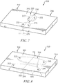
- a second integrally joined component 210 adapted for use in a gas turbine engine that may be made by method 1000 or 2000 is shown in Fig. 7 .
- the component 210 illustratively comprises ceramic matrix composite materials and is made up of a first subpart 212, a second subpart 214, and a pair of biscuits 216.
- the biscuits 216 extend into blind slots 213 formed in the first subpart 212 and into blind slots 215 formed in the second subpart 214 to form a joint 220.
- the joint 220 is coinfiltrated with ceramic-containing matrix material to integrally join the first subpart 212, the second subpart 214, and the biscuit 216.
- the first subpart 212, the second subpart 214, and the biscuits 216 are each made up of stacked sheets or plies of reinforcement material that are suspended in a ceramic matrix.
- fibers of the stacked plies comprise silicon-carbide but may comprise other ceramic-containing materials or other non-ceramic materials.
- one or more of the first subpart 212, the second subpart 214, and the biscuits 216 may comprise other configurations of reinforcement fibers suspended in a matrix, monolithic ceramic-containing materials, or other materials adapted for use in a gas turbine engine.
- the biscuits 216 are round, disk-shaped components as shown in Fig. 7 .
- the blind slots 213, 215 are shaped to receive substantially all of the biscuits 216 so that end faces 222, 224 of the first subpart 212 and the second subpart 214 face and engage one another in the illustrative component 210.
- the biscuits 216 are spaced apart from an outer surface 225 of the component 210.
- a third integrally joined component 310 adapted for use in a gas turbine engine that may be made by method 1000 or 2000 is shown in Fig. 8 .
- the component 310 illustratively comprises ceramic matrix composite materials and is made up of a first subpart 312, a second subpart 314, and a pair of biscuits 316.
- the biscuits 316 extend into blind slots 313 formed in the first subpart 312 and into blind slots 315 formed in the second subpart 314 to form a joint 320.
- the joint 320 is coinfiltrated with ceramic-containing matrix material to integrally join the first subpart 312, the second subpart 314, and the biscuits 316.
- the first subpart 312, the second subpart 314, and the biscuits 316 are each made up of stacked sheets or plies of reinforcement material that are suspended in a ceramic matrix.
- fibers of the stacked plies comprise silicon-carbide but may comprise other ceramic-containing materials or other non-ceramic materials.
- one or more of the first subpart 312, the second subpart 314, and the biscuits 316 may comprise other configurations of reinforcement fibers suspended in a matrix, monolithic ceramic-containing materials, or other materials adapted for use in a gas turbine engine.
- the biscuits 316 are oblong, disk-shaped components as shown in Fig. 8 .
- the blind slots 313, 315 are shaped to receive substantially all of the biscuits 316 so that end faces 322, 324 of the first subpart 312 and the second subpart 314 face and engage one another in the illustrative component 310.
- the biscuits 316 are spaced apart from an outer surface 325 of the component 310.
- a fourth integrally joined component 410 adapted for use in a gas turbine engine that may be made by method 1000 or 2000 is shown in Fig. 9 .
- the component 410 illustratively comprises ceramic matrix composite materials and is made up of a first subpart 412, a second subpart 414, and a biscuit 416.
- the biscuit 416 extends into a blind slot 413 formed in the first subpart 412 and into a blind slot 415 formed in the second subpart 414 to form a joint 420.
- the joint 420 is coinfiltrated with ceramic-containing matrix material to integrally join the first subpart 412, the second subpart 414, and the biscuit 416.
- the first subpart 412, the second subpart 414, and the biscuit 416 are each made up of stacked sheets or plies of reinforcement material that are suspended in a ceramic matrix.
- fibers of the stacked plies comprise silicon-carbide but may comprise other ceramic-containing materials or other non-ceramic materials.
- one or more of the first subpart 412, the second subpart 414, and the biscuits 416 may comprise other configurations of reinforcement fibers suspended in a matrix, monolithic ceramic-containing materials, or other materials adapted for use in a gas turbine engine.
- the biscuit 416 is an oblong, disk-shaped component as shown in Fig. 9 .
- the blind slots 413, 415 are shaped to receive substantially all of the biscuit 416 so that end faces 422, 424 of the first subpart 412 and the second subpart 414 face and engage one another in the illustrative component 410.
- the biscuit 416 is spaced apart from an outer surface 425 of the component 410.
- a fifth integrally joined component 510 adapted for use in a gas turbine engine that may be made by method 1000 or 2000 is shown in Fig. 10 .
- the component 510 illustratively comprises ceramic matrix composite materials and is made up of a first subpart 512, a second subpart 514, and a pair of biscuits 516.
- the biscuits 516 extend into blind slots 513 formed in the first subpart 512 and into blind slots 515 formed in the second subpart 514 to form a joint 520.
- the joint 520 is coinfiltrated with ceramic-containing matrix material to integrally join the first subpart 512, the second subpart 514, and the biscuits 516.
- the first subpart 512, the second subpart 514, and the biscuits 516 are each made up of stacked sheets or plies of reinforcement material that are suspended in a ceramic matrix.
- fibers of the stacked plies comprise silicon-carbide but may comprise other ceramic-containing materials or other non-ceramic materials.
- one or more of the first subpart 512, the second subpart 514, and the biscuits 516 may comprise other configurations of reinforcement fibers suspended in a matrix, monolithic ceramic-containing materials, or other materials adapted for use in a gas turbine engine.
- the biscuits 516 are rectangular components as shown in Fig. 10 .
- the blind slots 513, 515 are shaped to receive substantially all of the biscuits 516 so that end faces 522, 524 of the first subpart 512 and the second subpart 514 face and engage one another in the illustrative component 510.
- the biscuits 516 are spaced apart from an outer surface 525 of the component 510.
- a sixth integrally joined component 610 adapted for use in a gas turbine engine that may be made by method 1000 or 2000 is shown in Fig. 11 .
- the component 610 illustratively comprises ceramic matrix composite materials and is made up of a first subpart 612, a second subpart 614, and a biscuit 616.
- the biscuit 616 extends into a slot 613 formed in the first subpart 612 and into a slot 615 formed in the second subpart 614 to form a joint 620.
- the joint 620 is coinfiltrated with ceramic-containing matrix material to integrally join the first subpart 612, the second subpart 614, and the biscuit 616.
- the first subpart 612, the second subpart 614, and the biscuit 616 are each made up of stacked sheets or plies of reinforcement material that are suspended in a ceramic matrix.
- fibers of the stacked plies comprise silicon-carbide but may comprise other ceramic-containing materials or other non-ceramic materials.
- one or more of the first subpart 612, the second subpart 614, and the biscuit 616 may comprise other configurations of reinforcement fibers suspended in a matrix, monolithic ceramic-containing materials, or other materials adapted for use in a gas turbine engine.
- the biscuit 616 is a rectangular component as shown in Fig. 11 .
- the slots 613, 615 are shaped to receive substantially all of the biscuit 616 so that end faces 622, 624 of the first subpart 612 and the second subpart 614 face and engage one another in the illustrative component 610.
- the biscuit 616 illustratively forms a portion of an outer surface 625 of the component 610.
- a seventh integrally joined component 710 adapted for use in a gas turbine engine that may be made by method 1000 or 2000 is shown in Fig. 12 .
- the component 710 illustratively comprises ceramic matrix composite materials and is made up of a first subpart 712, a second subpart 714, and a biscuit 716.
- the biscuit 716 extends into a blind slot 713 formed in the first subpart 712 and into a blind slot 715 formed in the second subpart 714 to form a joint 720.
- the joint 720 is coinfiltrated with ceramic-containing matrix material to integrally join the first subpart 712, the second subpart 714, and the biscuit 716.
- the first subpart 712, the second subpart 714, and the biscuits 716 are each made up of stacked sheets or plies of reinforcement material that are suspended in a ceramic matrix.
- fibers of the stacked plies comprise silicon-carbide but may comprise other ceramic-containing materials or other non-ceramic materials.
- one or more of the first subpart 712, the second subpart 714, and the biscuit 716 may comprise other configurations of reinforcement fibers suspended in a matrix, monolithic ceramic-containing materials, or other materials adapted for use in a gas turbine engine.
- the biscuit 716 is a diamond shaped component as shown in Fig. 12 .
- the blind slots 713, 715 are shaped to receive substantially all of the biscuit 716 so that end faces 722, 724 of the first subpart 712 and the second subpart 714 face and engage one another in the illustrative component 710.
- the biscuit 716 is spaced apart from an outer surface 725 of the component 710.
- two or more silicon-carbide (SiC) fiber preforms with protective CVI can be joined with a third preform, or "biscuit", using the same slurry infiltration and subsequent melt infiltration as a single component.
- This may provide robust, simple, individual components that can be joined to make more robust complex components.
- a simple butt joint can be avoided to provide mechanical robustness.
- a third piece, or "biscuit” of different geometries is placed interlaminarly into two other components before slurry and melt infiltration is used to consolidate the part.
- a separate, or third, piece provides a joint that does not extend completely through a thickness of the resulting part and may give better interlaminar mechanical capability.
Description
- The present disclosure relates generally to ceramic matrix composite component manufacture, and more specifically to joining of ceramic matrix composite components.
- Reinforced ceramic matrix composites can be well suited for structural applications because of their potential toughness, thermal resistance, high temperature strength and chemical stability. These composites can be produced by the addition of whiskers, fibers, platelets, or other reinforcements to a ceramic matrix.
- Joining ceramic matrix composite components to one another can present challenges. In some joined ceramic matrix composite component assemblies, metallic braze joints couple separate ceramic matrix composite components to provide an integrated assembly. These metallic braze joints can degrade the mechanical integrity of the ceramic matrix composite components. In addition, these metallic braze joints can reduce the temperature capability of the ceramic matrix components due to suppression of a silicon melting point within the ceramic matrix composite components. The manufacture of an integral ceramic matrix composite component for a gas turbine engine is known from
EP 1 367 037 A2 - The present disclosure may comprise one or more of the following features and combinations thereof.
- A method of making an integrated ceramic matrix composite component for use in a gas turbine engine is disclosed in this paper. The method may include manufacturing a first green body subpart formed to include a first slot, manufacturing a second green body subpart formed to include a second slot, inserting a green body biscuit into the first slot of the first green body subpart and the second slot of the second green body subpart to create a green assembly with a joint between the first green body subpart and the second green body subpart, and slurry infiltrating the green assembly with ceramic-containing matrix to integrally join the green assembly and produce an integrated ceramic matrix composite component.
- In some embodiments, the method may include vapor infiltrating the first green body subpart, the second green body subpart, and the green body biscuit with ceramic-containing matrix to at least partially rigidify the first green body subpart, the second green body subpart, and the green body biscuit. The step of vapor infiltrating may be performed before the step of inserting the green body biscuit into the first slot of the first green body subpart and the second slot of the second green body subpart to create a green assembly.
- In some embodiments, manufacturing the first green body subpart may include laying up a plurality of reinforcement sheets. The method may include chemical vapor infiltrating the first green body subpart with ceramic-containing matrix to at least partially rigidify the first green body subpart after laying up the plurality of reinforcement sheets. At least some of the plurality of reinforcement sheets may be formed to include cutouts that cooperate to define the first slot before the step of vapor infiltrating the first green body subpart with ceramic-containing matrix.
- In some embodiments, the method may include machining at least some of the plurality of reinforcement sheets to define the first slot. This machining may take place after the step of chemical vapor infiltrating the first green body subpart with ceramic-containing matrix.
- In some embodiments, each of the plurality of reinforcement sheets included in the first green body subpart may comprise a ceramic-containing fiber. The ceramic-containing fiber may comprise silicon-carbide and the ceramic-containing matrix comprises silicon-carbide.
- In some embodiments, the method may include melt infiltrating the first green body subpart, the second green body subpart, and the green body biscuit with ceramic-containing matrix to integrally join the green assembly. The step of melt infiltrating may be performed after the step of slurry infiltrating the green assembly with ceramic-containing matrix.
- According to another aspect of the present disclosure, a method of making an integrated ceramic matrix composite component for use in a gas turbine engine is taught. The method may include the steps of chemical vapor infiltrating a first green body subpart, a second green body subpart, and a green body biscuit to at least partially rigidify the first green body subpart, the second green body subpart, and the green body biscuit, inserting the green body biscuit into a first slot formed in the first green body subpart and a second slot formed in the second green body subpart, and slurry infiltrating the first green body subpart, the second green body subpart, and the green body biscuit to produce an integrated ceramic matrix composite component.
- In some embodiments, the step of slurry infiltrating the first green body subpart, the second green body subpart, and the green body biscuit may be performed after inserting the green body biscuit into the first slot formed in the first green body subpart and the second slot formed in the second green body subpart. The step of chemical vapor infiltrating may be performed before the step of inserting the green body biscuit into the first slot of the first green body subpart and the second slot of the second green body subpart.
- In some embodiments, the first green body subpart may include a plurality of reinforcement sheets adapted to be suspended in ceramic-containing matrix. At least some of the plurality of reinforcement sheets may be formed to include cutouts that cooperate to define the first slot before the step of vapor infiltrating the first green body subpart with ceramic-containing matrix.
- In some embodiments, the method may include machining at least some of the plurality of reinforcement sheets to define the first slot after the step of chemically infiltrating the first green body subpart with ceramic-containing matrix.
- In some embodiments, each of the plurality of reinforcement sheets included in the first green body subpart may comprise a ceramic-containing fiber.
- In some embodiments, the method may include melt infiltrating the first green body subpart, the second green body subpart, and the green body biscuit with ceramic-containing matrix.
- According to yet another aspect of the present disclosure, an integrated ceramic-matrix composite component for use in a gas turbine engine is taught. The component may include a first subpart formed to include a first blind slot, a second subpart formed to include a second blind slot, and a biscuit that extends into the first blind slot and the second blind slot to form a joint between the first subpart and the second subpart, wherein the joint is coinfiltrated with ceramic-containing matrix material to integrally join the first subpart, the second subpart, and the biscuit.
- These and other features of the present disclosure will become more apparent from the following description of the illustrative embodiments.
-
-
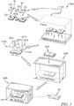
Fig. 1 is a perspective view of an integrally-joined ceramic matrix composite component showing that the component includes a first ceramic matrix composite subpart, a second ceramic matrix composite subpart, and a single round disk-shaped biscuit that is received in slots formed in the first and the second subparts to form a joint between the first and the second subparts; -
Fig. 2 is an exploded perspective view of the integrally-joined ceramic matrix composite component showing slots formed in the first ceramic matrix composite subpart and the second ceramic matrix composite subpart sized to receive the single round disk-shaped biscuit; -
Fig. 3 is a perspective view of a first method for making the integrally-joined ceramic matrix composite component ofFig. 1 ; -
Fig. 4 is a diagrammatic view of the first method shown inFig. 3 for making the integrally-joined ceramic matrix composite component ofFig. 1 ; -
Fig. 5 is a perspective view of a second method for making the integrally-joined ceramic matrix composite component ofFig. 1 ; -
Fig. 6 is a diagrammatic view of the second method shown inFig. 5 for making the integrally-joined ceramic matrix composite component ofFig. 1 ; -
Fig. 7 is a perspective view of a second integrally-joined ceramic matrix composite component adapted to be made by one of the methods shown inFigs. 3-6 showing that the component includes a first ceramic matrix composite subpart, a second ceramic matrix composite subpart, and a pair of round disk-shaped biscuits; -
Fig. 8 is a perspective view of a third integrally-joined ceramic matrix composite component adapted to be made by one of the methods shown inFigs. 3-6 showing that the component includes a first ceramic matrix composite subpart, a second ceramic matrix composite subpart, and a pair of oblong oval-shaped biscuits; -
Fig. 9 is a perspective view of a fourth integrally-joined ceramic matrix composite component adapted to be made by one of the methods shown inFigs. 3-6 showing that the component includes a first ceramic matrix composite subpart, a second ceramic matrix composite subpart, and a single oblong oval-shaped biscuit; -
Fig. 10 is a perspective view of a fifth integrally-joined ceramic matrix composite component adapted to be made by one of the methods shown inFigs. 3-6 showing that the component includes a first ceramic matrix composite subpart, a second ceramic matrix composite subpart, and a pair of rectangular biscuits; -
Fig. 11 is a perspective view of a sixth integrally-joined ceramic matrix composite component adapted to be made by one of the methods shown inFigs. 3-6 showing that the component includes a first ceramic matrix composite subpart, a second ceramic matrix composite subpart, and a single rectangular biscuit; and -
Fig. 12 is a perspective view of a seventh integrally-joined ceramic matrix composite component adapted to be made by one of the methods shown inFigs. 3-6 showing that the component includes a first ceramic matrix composite subpart, a second ceramic matrix composite subpart, and a single diamond-shaped biscuit. - For the purposes of promoting an understanding of the principles of the disclosure, reference will now be made to a number of illustrative embodiments illustrated in the drawings and specific language will be used to describe the same.
- An integrally joined
component 10 adapted for use in a gas turbine engine is shown inFig. 1 . Thecomponent 10 illustratively comprises ceramic matrix composite materials and is made up of afirst subpart 12, asecond subpart 14, and abiscuit 16. Thebiscuit 16 extends into a firstblind slot 13 formed in thefirst subpart 12 and into a secondblind slot 15 formed in thesecond subpart 14 to form ajoint 20. Thejoint 20 is coinfiltrated with ceramic-containing matrix material to integrally join thefirst subpart 12, thesecond subpart 14, and thebiscuit 16. - The
first subpart 12, thesecond subpart 14, and thebiscuit 16 are each made up of stacked sheets orplies Fig. 3 . In the illustrative embodiment, fibers of the stacked plies comprise silicon-carbide but may comprise other ceramic-containing materials or other non-ceramic materials. In other embodiments, one or more of thefirst subpart 12, thesecond subpart 14, and thebiscuit 16 may comprise other configurations of reinforcement fibers suspended in a matrix, monolithic ceramic-containing materials, or other materials adapted for use in a gas turbine engine. - In the illustrative embodiment, the
biscuit 16 is a round, disk-shaped component as shown inFig. 2 . The first and the secondblind slots biscuit 16 so that end faces 22, 24 of thefirst subpart 12 and thesecond subpart 14 face and engage one another in theillustrative component 10. Thebiscuit 16 is spaced apart from anouter surface 25 of thecomponent 10. - For example, the integrally joined
component 10 or similar components may be used in a gas turbine engine to provide a turbine blade track, in a combustion liner, a heat shield or the like. The integrally joinedcomponent 10 may be adapted for use in very high temperature environments and may be used in various applications requiring high temperature service. - A
first method 1000 of making the integrally joined ceramicmatrix composite component 10 is shown in illustratively inFig. 3 and diagrammatically inFig. 4 . Astep 1100 of themethod 1000 is manufacturing green bodies to be coinfiltrated. Particularly, instep 1100, a firstgreen body subpart 1012 formed to include afirst slot 1013, a secondgreen body subpart 1014 formed to include asecond slot 1015, and agreen body biscuit 1016 are manufactured. - The
step 1100 of manufacturing green bodies includes laying uppreshaped reinforcement sheets step 1110. Thestep 1100 of manufacturing green bodies also includes at least partially rigidifying the laid upreinforcement sheets step 1120 as shown inFigs. 3 and4 . In some embodiments, rigidizing thereinforcement sheets step 1120 may alternatively or additionally include chemical vapor infiltration (CVI). Additionally, in some embodiments, thestep 1100 may include an optional machining of therigidized reinforcement sheets step 1130 as shown inFig. 4 . - At least some of the plurality of
reinforcement sheets cutouts Fig. 3 . The plurality ofreinforcement sheets green body biscuit 1016 when rigidized. - During rigidization of the laid up
reinforcement sheets step 1120, CVD or CVI may be used to build up one or more layers of matrix on the ceramic fibers included in the laid upreinforcement sheets Fig. 3 . - The starting material for CVI may include a gaseous precursor that undergoes a chemical reaction to yield a solid and may be performed at temperatures between about 900°C and about 1300°C. CVI may be performed at relatively low pressure and may use multiple cycles in the furnace. Silicon carbide may also be deposited to build up one or more layers on the fibers while the preform is in the reactor. The silicon carbide may provide additional protection to the fibers and may also increase the stiffness of the laid up
reinforcement sheets - The laid up
reinforcement sheets reinforcement sheets reinforcement sheets method 1000 may proceed. - A
step 1200 of themethod 1000 is assembling green bodies to be coinfiltrated as shown inFigs. 3 and4 . Particularly, instep 1200, thegreen body biscuit 1016 is inserted into afirst slot 1013 of the firstgreen body subpart 1012 and asecond slot 1015 of the secondgreen body subpart 1014 to create agreen assembly 1010 with a green joint 1020 between the firstgreen body subpart 1012 and the secondgreen body subpart 1014. - In some embodiments, the
biscuit 1016 may be fully processed (rigidized) prior to assembly instep 1200. Such fully processedbiscuits 1016 may be preferred when machining of thebiscuits 1016 ahead of assembly is required. - A
step 1300 of themethod 1000 is slurry infiltrating thegreen assembly 1010 as shown inFigs. 3 and4 . Slurry infiltration instep 1300 may include infiltrating thegreen assembly 1010 with slurry. Dispersing the slurry throughout thegreen assembly 1010 may include immersing the preforms in the slurry composition. The slurry may include particles of silicon carbide and optionally carbon. The slurry may flow into the spaces, pores, or openings between the fibers of thegreen assembly 1010 such that the slurry particles may uniformly impregnate the pores of thegreen assembly 1010 and reside in the interstices between fibers of thegreen assembly 1010. The slurry infiltration process may form a resultant matrix for the component with a porosity of between about, or between precisely, 35% and about 50%. - Prior to immersion, the fibers of the
green assembly 1010 may optionally be prepared for slurry infiltration by exposing the fibers to a solution including, for example, water, solvents, surfactants and the like to aid impregnation of the fibers. Optionally, a vacuum may be drawn prior to slurry introduction to purge gas from thegreen assembly 1010 and further enhance impregnation. Slurry infiltration may be conducted at any suitable temperature such as at room temperature (about 20 °C to about 35 °C). The slurry infiltration may be enhanced by application of external pressure after slurry introduction such as at one atmosphere pressure gradient. - A
step 1400 of themethod 1000 includes melt infiltration of thegreen assembly 1010 as shown inFigs. 3 and4 . During melt infiltration a molten metal or alloy may wick between the openings of thegreen assembly 1010. In various embodiments, the molten metal or alloy may have composition that includes silicon, boron, aluminum, yttrium, titanium, zirconium, oxides thereof, carbides thereof, and mixtures and combinations thereof. In some instances, carbonaceous powder may be added to assist the melt infiltration. The molten metal or alloy may wick into the remaining pores of the preform through capillary pressure. For example, molten silicon metal may wick into the pores and form silicon carbide to create a matrix between the fibers resulting in a relatively dense integrally joinedcomponent 10 compared to thegreen assembly 1010. For example, after thegreen assembly 1010 has been densified, the integrally joinedcomponent 10 may have a porosity of between about 1 percent and about 10 percent by volume. - In one example, a temperature for melt infiltration of silicon may be between about 1400 °C and about 1500 °C. The duration of the melt infiltration may be between about 15 minutes and 4 hours. The melt infiltration process may optionally be carried out under vacuum, but in other embodiments melt infiltration may be carried out with an inert gas under atmospheric pressure to limit evaporation losses. The co-infiltration processes described herein may create the integrally joined
component 10 in which thefirst subpart 12, thesecond subpart 14, and thebiscuit 16 are a one-piece, continuous structure. - A
second method 2000 of making the integrally joined ceramicmatrix composite component 10 is shown in illustratively inFig. 5 and diagrammatically inFig. 6 . Astep 2100 of themethod 1000 is manufacturing green bodies to be coinfiltrated. Particularly, instep 2100, a firstgreen body subpart 1012 formed to include afirst slot 1013, a secondgreen body subpart 1014 formed to include asecond slot 1015, and agreen body biscuit 1016 are manufactured. - The
step 2100 of manufacturing green bodies includes laying upreinforcement sheets step 2110. Thestep 2100 of manufacturing green bodies also includes at least partially rigidifying the laid upreinforcement sheets step 2120 as shown inFigs. 5 and6 . In some embodiments, rigidizing thereinforcement sheets step 2120 may alternatively or additionally include chemical vapor infiltration (CVI). Additionally, thestep 2100 includes machining of the rigidized laid upreinforcement sheets step 1130 as shown inFig. 5 . - During rigidization of the laid up
reinforcement sheets step 2120, CVD or CVI may be used to build up one or more layers of matrix on the ceramic fibers included in the laid upreinforcement sheets Fig. 5 . - The starting material for CVI may include a gaseous precursor that undergoes a chemical reaction to yield a solid and may be performed at temperatures between about 900°C and about 1300°C. CVI may be performed at relatively low pressure and may use multiple cycles in the furnace. Silicon carbide may also be deposited to build up one or more layers on the fibers while the preform is in the furnace. The silicon carbide may provide additional protection to the fibers and may also increase the stiffness of the laid up
reinforcement sheets - The laid up
reinforcement sheets reinforcement sheets reinforcement sheets method 2000 may proceed. - Upon rigidization, the laid up
reinforcement sheets step 2130 to formgreen body slots Fig. 5 . Additionally, when rigidized, the laid upreinforcement sheets step 2130 to provide a round shape that characterizes thegreen body biscuit 1016. - A
step 2200 of themethod 2000 is assembling green bodies to be coinfiltrated as shown inFigs. 5 and6 . Particularly, instep 2200, thegreen body biscuit 1016 is inserted into afirst slot 1013 of the firstgreen body subpart 1012 and asecond slot 1015 of the secondgreen body subpart 1014 to create agreen assembly 1010 with a green joint 1020 between the firstgreen body subpart 1012 and the secondgreen body subpart 1014. - In some embodiments, the
biscuit 1016 may be fully processed (rigidized) prior to assembly instep 2200. Such fully processedbiscuits 1016 may be preferred when machining of thebiscuits 1016 ahead of assembly is required. - A
step 2300 of themethod 2000 is slurry infiltrating thegreen assembly 1010 as shown inFigs. 5 and6 . Slurry infiltration instep 2300 may include infiltrating thegreen assembly 1010 with slurry. Dispersing the slurry throughout thegreen assembly 1010 may include immersing the preforms in the slurry composition. The slurry may include particles of carbon and optionally silicon carbide. The slurry may flow into the spaces, pores, or openings between the fibers of thegreen assembly 1010 such that the slurry particles may uniformly impregnate the pores of thegreen assembly 1010 and reside in the interstices between fibers of thegreen assembly 1010. The slurry infiltration process may form a resultant matrix for the component with a porosity of between about 35% and about 50%. - Prior to immersion, the fibers of the
green assembly 1010 may optionally be prepared for slurry infiltration by exposing the fibers to a solution including, for example, water, solvents, surfactants and the like to aid impregnation of the fibers. Optionally, a vacuum may be drawn prior to slurry introduction to purge gas from thegreen assembly 1010 and further enhance impregnation. Slurry infiltration may be conducted at any suitable temperature such as at room temperature (about 20 °C to about 35 °C). The slurry infiltration may be enhanced by application of external pressure after slurry introduction such as at one atmosphere pressure gradient. - A
step 2400 of themethod 2000 includes melt infiltration of thegreen assembly 1010 as shown inFigs. 5 and6 . During melt infiltration a molten metal or alloy may wick between the openings of thegreen assembly 1010. In various embodiments, the molten metal or alloy may have composition that includes silicon, boron, aluminum, yttrium, titanium, zirconium, oxides thereof, and mixtures and combinations thereof. In some instances, graphite powder may be added to assist the melt infiltration. The molten metal or alloy may wick into the remaining pores of the preform through capillary pressure. For example, molten silicon metal may wick into the pores and form silicon carbide to create a matrix between the fibers resulting in a relatively dense integrally joinedcomponent 10 compared to thegreen assembly 1010. For example, after thegreen assembly 1010 has been densified, the integrally joinedcomponent 10 may have a porosity of between about 1 percent and about 10 percent by volume. - In one example, a temperature for melt infiltration of silicon may be between about 1400 °C and about 1500 °C. The duration of the melt infiltration may be between about 15 minutes and 4 hours. The melt infiltration process may optionally be carried out under vacuum, but in other embodiments melt infiltration may be carried out with an inert gas under atmospheric pressure to limit evaporation losses. The co-infiltration processes described herein may create the integrally joined
component 10 in which thefirst subpart 12, thesecond subpart 14, and thebiscuit 16 are a one-piece, continuous structure. - A second integrally joined
component 210 adapted for use in a gas turbine engine that may be made bymethod Fig. 7 . Thecomponent 210 illustratively comprises ceramic matrix composite materials and is made up of afirst subpart 212, asecond subpart 214, and a pair ofbiscuits 216. Thebiscuits 216 extend intoblind slots 213 formed in thefirst subpart 212 and intoblind slots 215 formed in thesecond subpart 214 to form a joint 220. The joint 220 is coinfiltrated with ceramic-containing matrix material to integrally join thefirst subpart 212, thesecond subpart 214, and thebiscuit 216. - The
first subpart 212, thesecond subpart 214, and thebiscuits 216 are each made up of stacked sheets or plies of reinforcement material that are suspended in a ceramic matrix. In the illustrative embodiment, fibers of the stacked plies comprise silicon-carbide but may comprise other ceramic-containing materials or other non-ceramic materials. In other embodiments, one or more of thefirst subpart 212, thesecond subpart 214, and thebiscuits 216 may comprise other configurations of reinforcement fibers suspended in a matrix, monolithic ceramic-containing materials, or other materials adapted for use in a gas turbine engine. - In the illustrative embodiment, the
biscuits 216 are round, disk-shaped components as shown inFig. 7 . Theblind slots biscuits 216 so that end faces 222, 224 of thefirst subpart 212 and thesecond subpart 214 face and engage one another in theillustrative component 210. Thebiscuits 216 are spaced apart from anouter surface 225 of thecomponent 210. - A third integrally joined
component 310 adapted for use in a gas turbine engine that may be made bymethod Fig. 8 . Thecomponent 310 illustratively comprises ceramic matrix composite materials and is made up of afirst subpart 312, asecond subpart 314, and a pair ofbiscuits 316. Thebiscuits 316 extend intoblind slots 313 formed in thefirst subpart 312 and intoblind slots 315 formed in thesecond subpart 314 to form a joint 320. The joint 320 is coinfiltrated with ceramic-containing matrix material to integrally join thefirst subpart 312, thesecond subpart 314, and thebiscuits 316. - The
first subpart 312, thesecond subpart 314, and thebiscuits 316 are each made up of stacked sheets or plies of reinforcement material that are suspended in a ceramic matrix. In the illustrative embodiment, fibers of the stacked plies comprise silicon-carbide but may comprise other ceramic-containing materials or other non-ceramic materials. In other embodiments, one or more of thefirst subpart 312, thesecond subpart 314, and thebiscuits 316 may comprise other configurations of reinforcement fibers suspended in a matrix, monolithic ceramic-containing materials, or other materials adapted for use in a gas turbine engine. - In the illustrative embodiment, the
biscuits 316 are oblong, disk-shaped components as shown inFig. 8 . Theblind slots biscuits 316 so that end faces 322, 324 of thefirst subpart 312 and thesecond subpart 314 face and engage one another in theillustrative component 310. Thebiscuits 316 are spaced apart from anouter surface 325 of thecomponent 310. - A fourth integrally joined
component 410 adapted for use in a gas turbine engine that may be made bymethod Fig. 9 . Thecomponent 410 illustratively comprises ceramic matrix composite materials and is made up of afirst subpart 412, asecond subpart 414, and abiscuit 416. Thebiscuit 416 extends into ablind slot 413 formed in thefirst subpart 412 and into ablind slot 415 formed in thesecond subpart 414 to form a joint 420. The joint 420 is coinfiltrated with ceramic-containing matrix material to integrally join thefirst subpart 412, thesecond subpart 414, and thebiscuit 416. - The
first subpart 412, thesecond subpart 414, and thebiscuit 416 are each made up of stacked sheets or plies of reinforcement material that are suspended in a ceramic matrix. In the illustrative embodiment, fibers of the stacked plies comprise silicon-carbide but may comprise other ceramic-containing materials or other non-ceramic materials. In other embodiments, one or more of thefirst subpart 412, thesecond subpart 414, and thebiscuits 416 may comprise other configurations of reinforcement fibers suspended in a matrix, monolithic ceramic-containing materials, or other materials adapted for use in a gas turbine engine. - In the illustrative embodiment, the
biscuit 416 is an oblong, disk-shaped component as shown inFig. 9 . Theblind slots biscuit 416 so that end faces 422, 424 of thefirst subpart 412 and thesecond subpart 414 face and engage one another in theillustrative component 410. Thebiscuit 416 is spaced apart from anouter surface 425 of thecomponent 410. - A fifth integrally joined
component 510 adapted for use in a gas turbine engine that may be made bymethod Fig. 10 . Thecomponent 510 illustratively comprises ceramic matrix composite materials and is made up of afirst subpart 512, asecond subpart 514, and a pair ofbiscuits 516. Thebiscuits 516 extend intoblind slots 513 formed in thefirst subpart 512 and intoblind slots 515 formed in thesecond subpart 514 to form a joint 520. The joint 520 is coinfiltrated with ceramic-containing matrix material to integrally join thefirst subpart 512, thesecond subpart 514, and thebiscuits 516. - The
first subpart 512, thesecond subpart 514, and thebiscuits 516 are each made up of stacked sheets or plies of reinforcement material that are suspended in a ceramic matrix. In the illustrative embodiment, fibers of the stacked plies comprise silicon-carbide but may comprise other ceramic-containing materials or other non-ceramic materials. In other embodiments, one or more of thefirst subpart 512, thesecond subpart 514, and thebiscuits 516 may comprise other configurations of reinforcement fibers suspended in a matrix, monolithic ceramic-containing materials, or other materials adapted for use in a gas turbine engine. - In the illustrative embodiment, the
biscuits 516 are rectangular components as shown inFig. 10 . Theblind slots biscuits 516 so that end faces 522, 524 of thefirst subpart 512 and thesecond subpart 514 face and engage one another in theillustrative component 510. Thebiscuits 516 are spaced apart from anouter surface 525 of thecomponent 510. - A sixth integrally joined
component 610 adapted for use in a gas turbine engine that may be made bymethod Fig. 11 . Thecomponent 610 illustratively comprises ceramic matrix composite materials and is made up of afirst subpart 612, asecond subpart 614, and abiscuit 616. Thebiscuit 616 extends into aslot 613 formed in thefirst subpart 612 and into aslot 615 formed in thesecond subpart 614 to form a joint 620. The joint 620 is coinfiltrated with ceramic-containing matrix material to integrally join thefirst subpart 612, thesecond subpart 614, and thebiscuit 616. - The
first subpart 612, thesecond subpart 614, and thebiscuit 616 are each made up of stacked sheets or plies of reinforcement material that are suspended in a ceramic matrix. In the illustrative embodiment, fibers of the stacked plies comprise silicon-carbide but may comprise other ceramic-containing materials or other non-ceramic materials. In other embodiments, one or more of thefirst subpart 612, thesecond subpart 614, and thebiscuit 616 may comprise other configurations of reinforcement fibers suspended in a matrix, monolithic ceramic-containing materials, or other materials adapted for use in a gas turbine engine. - In the illustrative embodiment, the
biscuit 616 is a rectangular component as shown inFig. 11 . Theslots biscuit 616 so that end faces 622, 624 of thefirst subpart 612 and thesecond subpart 614 face and engage one another in theillustrative component 610. Thebiscuit 616 illustratively forms a portion of anouter surface 625 of thecomponent 610. - A seventh integrally joined
component 710 adapted for use in a gas turbine engine that may be made bymethod Fig. 12 . Thecomponent 710 illustratively comprises ceramic matrix composite materials and is made up of afirst subpart 712, asecond subpart 714, and abiscuit 716. Thebiscuit 716 extends into ablind slot 713 formed in thefirst subpart 712 and into ablind slot 715 formed in thesecond subpart 714 to form a joint 720. The joint 720 is coinfiltrated with ceramic-containing matrix material to integrally join thefirst subpart 712, thesecond subpart 714, and thebiscuit 716. - The
first subpart 712, thesecond subpart 714, and thebiscuits 716 are each made up of stacked sheets or plies of reinforcement material that are suspended in a ceramic matrix. In the illustrative embodiment, fibers of the stacked plies comprise silicon-carbide but may comprise other ceramic-containing materials or other non-ceramic materials. In other embodiments, one or more of thefirst subpart 712, thesecond subpart 714, and thebiscuit 716 may comprise other configurations of reinforcement fibers suspended in a matrix, monolithic ceramic-containing materials, or other materials adapted for use in a gas turbine engine. - In the illustrative embodiment, the
biscuit 716 is a diamond shaped component as shown inFig. 12 . Theblind slots biscuit 716 so that end faces 722, 724 of thefirst subpart 712 and thesecond subpart 714 face and engage one another in theillustrative component 710. Thebiscuit 716 is spaced apart from anouter surface 725 of thecomponent 710. - According to the present disclosure, two or more silicon-carbide (SiC) fiber preforms with protective CVI can be joined with a third preform, or "biscuit", using the same slurry infiltration and subsequent melt infiltration as a single component. This may provide robust, simple, individual components that can be joined to make more robust complex components.
- The general process flows shown in
Figs. 3-6 of how the presently disclosed methods work provide two different paths with the first forming the general joint geometry in fiber layup and the other forming the general joint geometry with a machining process after CVI. Both form a joined component after the parts have been infiltrated with slurry and subsequently infiltrated with a molten medium (usually Si metal alloy). - Another aspect of the integral joining method taught in this disclosure is that a simple butt joint can be avoided to provide mechanical robustness. Illustratively, in the disclosed embodiments a third piece, or "biscuit", of different geometries is placed interlaminarly into two other components before slurry and melt infiltration is used to consolidate the part. A separate, or third, piece provides a joint that does not extend completely through a thickness of the resulting part and may give better interlaminar mechanical capability.
- While the disclosure has been illustrated and described in detail in the foregoing drawings and description, the same is to be considered as exemplary and not restrictive in character, it being understood that only illustrative embodiments thereof have been shown and described.
Claims (15)
- A method of making an integrated ceramic matrix composite component (10) for use in a gas turbine engine, the method comprising the steps of
manufacturing a first green body (1012) formed to include a first blind slot (1013), manufacturing a second green body subpart (1014) formed to include a second blind slot (1015), inserting a green body biscuit (1016) into the first blind slot (1013) of the first green body subpart (1012) and the second blind slot (1015) of the second green body subpart (1014) to create a green assembly (1010) with a joint between the first green body subpart (1012) and the second green body subpart (1014), and
slurry infiltrating the green assembly (1010) with ceramic-containing matrix to integrally join the green assembly (1010) and produce an integrated ceramic matrix composite component (10). - The method of claim 1, further comprising vapor infiltrating the first green body subpart, the second green body subpart, and the green body biscuit with ceramic-containing matrix to at least partially rigidify the first green body subpart, the second green body subpart, and the green body biscuit.
- The method of claim 2, wherein the step of vapor infiltrating is performed before the step of inserting the green body biscuit into the first blind slot of the first green body subpart and the second blind slot of the second green body subpart to create a green assembly.
- The method of claim 1, wherein manufacturing the first green body subpart includes laying up a plurality of reinforcement sheets (121, 122).
- The method of claim 4, further comprising chemical vapor infiltrating the first green body subpart with ceramic-containing matrix to at least partially rigidify the first green body subpart after laying up the plurality of reinforcement sheets (121, 122).
- The method of claim 5, wherein at least some of the plurality of reinforcement sheets are formed to include cutouts (125) that cooperate to define the first blind slot before the step of vapor infiltrating the first green body subpart with ceramic-containing matrix.
- The method of claim 5, further comprising machining at least some of the plurality of reinforcement sheets to define the first blind slot after the step of chemical vapor infiltrating the first green body subpart with ceramic-containing matrix.
- The method of claim 4, wherein each of the plurality of reinforcement sheets included in the first green body subpart comprises a ceramic-containing fiber, optionally wherein the ceramic-containing fiber comprises silicon-carbide and the ceramic-containing matrix comprises silicon-carbide.
- The method of claim 1, further comprising melt infiltrating the first green body subpart, the second green body subpart, and the green body biscuit with ceramic-containing matrix to integrally join the green assembly, optionally wherein the step of melt infiltrating is performed after the step of slurry infiltrating the green assembly with ceramic-containing matrix.
- A method of making an integrated ceramic matrix composite component (10) for use in a gas turbine engine, the method comprising the steps of
chemical vapor infiltrating a first green body subpart (1012), a second green body subpart (1014), and a green body biscuit (1016) to at least partially rigidify the first green body subpart (1012), the second green body subpart (1014), and the green body biscuit (1016), inserting the green body biscuit (1016) into a first blind slot (1013) formed in the first green body subpart (1012) and a second blind slot (1015) formed in the second green body subpart (1014), and
slurry infiltrating the first green body subpart (1012), the second green body subpart (1014), and the green body biscuit (1016) to produce an integrated ceramic matrix composite component (10). - The method of claim 10, wherein the step of slurry infiltrating the first green body subpart, the second green body subpart, and the green body biscuit is performed after inserting the green body biscuit into the first blind slot formed in the first green body subpart and the second blind slot formed in the second green body subpart, optionally wherein the step of chemical vapor infiltrating is performed before the step of inserting the green body biscuit into the first blind slot of the first green body subpart and the second blind slot of the second green body subpart.
- The method of claim 10, wherein the first green body subpart includes a plurality of reinforcement sheets adapted to be suspended in ceramic-containing matrix.
- The method of claim 12, wherein:(i) at least some of the plurality of reinforcement sheets are formed to include cutouts that cooperate to define the first blind slot before the step of vapor infiltrating the first green body subpart with ceramic-containing matrix; or(ii) the method further comprises machining at least some of the plurality of reinforcement sheets to define the first blind slot after the step of chemically infiltrating the first green body subpart with ceramic-containing matrix; or(iii) each of the plurality of reinforcement sheets included in the first green body subpart comprises a ceramic-containing fiber.
- The method of claim 10, further comprising melt infiltrating the first green body subpart, the second green body subpart, and the green body biscuit with ceramic-containing matrix.
- An integrated ceramic-matrix composite component for use in a gas turbine engine, the component comprising
a first subpart (12, 212, 312, 412, 512, 612, 712) formed to include a first blind slot (13, 213, 313, 413, 513, 613, 713), a second subpart (14, 214, 314, 414, 514, 614, 714) formed to include a second blind slot (15, 215, 315, 415, 515, 615, 715), and
a biscuit (16, 216, 316, 416, 516, 616, 716) that extends into the first blind slot (13, 213, 313, 413, 513, 613, 713) and the second blind slot (15, 215, 315, 415, 515, 615, 715) to form a joint (20, 220, 320, 420, 520, 620, 720) between the first subpart (12, 212, 312, 412, 512, 612, 712) and the second subpart (14, 214, 314, 414, 514, 614, 714), wherein the joint (20, 220, 320, 420, 520, 620, 720) is coinfiltrated with ceramic-containing matrix material to integrally join the first subpart (12, 212, 312, 412, 512, 612, 712), the second subpart (14, 214, 314, 414, 514, 614, 714), and the biscuit (16, 216, 316, 416, 516, 616, 716).
Applications Claiming Priority (1)
| Application Number | Priority Date | Filing Date | Title |
|---|---|---|---|
| US201562182882P | 2015-06-22 | 2015-06-22 |
Publications (2)
| Publication Number | Publication Date |
|---|---|
| EP3109043A1 EP3109043A1 (en) | 2016-12-28 |
| EP3109043B1 true EP3109043B1 (en) | 2018-01-31 |
Family
ID=56296472
Family Applications (1)
| Application Number | Title | Priority Date | Filing Date |
|---|---|---|---|
| EP16172531.2A Active EP3109043B1 (en) | 2015-06-22 | 2016-06-01 | Method for integral joining infiltrated ceramic matrix composites |
Country Status (2)
| Country | Link |
|---|---|
| US (1) | US9938198B2 (en) |
| EP (1) | EP3109043B1 (en) |
Families Citing this family (9)
| Publication number | Priority date | Publication date | Assignee | Title |
|---|---|---|---|---|
| US10472976B2 (en) * | 2015-06-05 | 2019-11-12 | Rolls-Royce Corporation | Machinable CMC insert |
| US10458653B2 (en) * | 2015-06-05 | 2019-10-29 | Rolls-Royce Corporation | Machinable CMC insert |
| US10465534B2 (en) * | 2015-06-05 | 2019-11-05 | Rolls-Royce North American Technologies, Inc. | Machinable CMC insert |
| EP3511308B1 (en) * | 2016-09-06 | 2021-03-03 | IHI Corporation | Production method of ceramic matrix composite |
| US11149590B2 (en) | 2017-06-21 | 2021-10-19 | Rolls-Royce Corporation | Ceramic matrix composite joints |
| US10954809B2 (en) | 2017-06-26 | 2021-03-23 | Rolls-Royce High Temperature Composites Inc. | Ceramic matrix full hoop blade track |
| US11031643B2 (en) * | 2018-07-02 | 2021-06-08 | Faraday&Future Inc. | Systems, methods, and apparatus for optimizing battery module coolant fluid flow |
| FR3115534B1 (en) * | 2020-10-27 | 2022-10-28 | Safran Ceram | METHOD FOR MANUFACTURING A TURBOMACHINE BLADE IN COMPOSITE MATERIAL |
| FR3132928B1 (en) | 2022-02-21 | 2024-02-16 | Safran Ceram | ASSEMBLY FOR AN AIRCRAFT TURBOMACHINE |
Family Cites Families (31)
| Publication number | Priority date | Publication date | Assignee | Title |
|---|---|---|---|---|
| US3923314A (en) | 1973-12-06 | 1975-12-02 | Carborundum Co | Non-rigid seal for joining silicon carbide tubes and tube sheets in heat exchangers |
| FR2645223B1 (en) | 1989-03-30 | 1991-07-19 | Europ Propulsion | METHOD OF JOINING ELEMENTS FOR THE MANUFACTURE OF PARTS OF THERMOSTRUCTURAL COMPOSITE MATERIAL |
| DE69107079T2 (en) | 1990-07-12 | 1995-06-01 | Lanxide Technology Co Ltd | CONNECTION METHODS FOR CERAMIC COMPOSITIONS. |
| US5296311A (en) | 1992-03-17 | 1994-03-22 | The Carborundum Company | Silicon carbide reinforced reaction bonded silicon carbide composite |
| US5447683A (en) | 1993-11-08 | 1995-09-05 | General Atomics | Braze for silicon carbide bodies |
| FR2732984B1 (en) | 1995-04-13 | 1997-07-04 | Europ Propulsion | PROCESS FOR MANUFACTURING COMPLEX ONE-PIECE STRUCTURAL PARTS IN COMPOSITE MATERIAL |
| US6280550B1 (en) | 1998-12-15 | 2001-08-28 | General Electric Company | Fabrication of composite articles having an infiltrated matrix |
| US6863759B2 (en) | 2001-01-24 | 2005-03-08 | M Cubed Technologies, Inc. | Methods for making composite bonded structures |
| US6648597B1 (en) * | 2002-05-31 | 2003-11-18 | Siemens Westinghouse Power Corporation | Ceramic matrix composite turbine vane |
| US7771160B2 (en) | 2006-08-10 | 2010-08-10 | United Technologies Corporation | Ceramic shroud assembly |
| US7665960B2 (en) | 2006-08-10 | 2010-02-23 | United Technologies Corporation | Turbine shroud thermal distortion control |
| FR2913717A1 (en) | 2007-03-15 | 2008-09-19 | Snecma Propulsion Solide Sa | Ring assembly for e.g. aircraft engine gas turbine, has centering unit constituted of metallic ring gear and bracket, and centering complete ring, where elastically deformable tab blocks rotation of ring around axis of ring |
| US8070427B2 (en) | 2007-10-31 | 2011-12-06 | General Electric Company | Gas turbines having flexible chordal hinge seals |
| US8568091B2 (en) | 2008-02-18 | 2013-10-29 | United Technologies Corporation | Gas turbine engine systems and methods involving blade outer air seals |
| FR2943942B1 (en) * | 2009-04-06 | 2016-01-29 | Snecma | PROCESS FOR MANUFACTURING A TURBOMACHINE BLADE OF COMPOSITE MATERIAL |
| US8167546B2 (en) | 2009-09-01 | 2012-05-01 | United Technologies Corporation | Ceramic turbine shroud support |
| US9506355B2 (en) | 2009-12-14 | 2016-11-29 | Snecma | Turbine engine blade or vane made of composite material, turbine nozzle or compressor stator incorporating such vanes and method of fabricating same |
| FR2957543B1 (en) | 2010-03-16 | 2012-07-27 | Commissariat Energie Atomique | METHOD FOR ASSEMBLING NON-REACTIVE BRAZING SIC-BASED MATERIAL PARTS, BRAZING COMPOSITIONS, AND JOINT AND ASSEMBLY OBTAINED THEREBY |
| US8753073B2 (en) | 2010-06-23 | 2014-06-17 | General Electric Company | Turbine shroud sealing apparatus |
| US8926270B2 (en) | 2010-12-17 | 2015-01-06 | General Electric Company | Low-ductility turbine shroud flowpath and mounting arrangement therefor |
| US8684689B2 (en) | 2011-01-14 | 2014-04-01 | Hamilton Sundstrand Corporation | Turbomachine shroud |
| US8985944B2 (en) | 2011-03-30 | 2015-03-24 | General Electric Company | Continuous ring composite turbine shroud |
| US20120301269A1 (en) | 2011-05-26 | 2012-11-29 | Ioannis Alvanos | Clearance control with ceramic matrix composite rotor assembly for a gas turbine engine |
| US8834106B2 (en) | 2011-06-01 | 2014-09-16 | United Technologies Corporation | Seal assembly for gas turbine engine |
| US9212560B2 (en) | 2011-06-30 | 2015-12-15 | United Technologies Corporation | CMC blade with integral 3D woven platform |
| US20130011248A1 (en) | 2011-07-05 | 2013-01-10 | United Technologies Corporation | Reduction in thermal stresses in monolithic ceramic or ceramic matrix composite shroud |
| US8511975B2 (en) | 2011-07-05 | 2013-08-20 | United Technologies Corporation | Gas turbine shroud arrangement |
| FR2980235B1 (en) | 2011-09-20 | 2015-04-17 | Snecma | RING FOR A TURBOMACHINE TURBINE |
| US9291060B2 (en) * | 2013-03-14 | 2016-03-22 | Rolls-Royce Corporation | High strength joints in ceramic matrix composite preforms |
| US9624786B2 (en) | 2013-03-15 | 2017-04-18 | Rolls-Royce Corporation | Braze materials and method for joining of ceramic matrix composites |
| CA2925588A1 (en) | 2015-04-29 | 2016-10-29 | Rolls-Royce Corporation | Brazed blade track for a gas turbine engine |
-
2016
- 2016-06-01 EP EP16172531.2A patent/EP3109043B1/en active Active
- 2016-06-21 US US15/188,159 patent/US9938198B2/en active Active
Non-Patent Citations (1)
| Title |
|---|
| None * |
Also Published As
| Publication number | Publication date |
|---|---|
| US20160368827A1 (en) | 2016-12-22 |
| US9938198B2 (en) | 2018-04-10 |
| EP3109043A1 (en) | 2016-12-28 |
Similar Documents
| Publication | Publication Date | Title |
|---|---|---|
| EP3109043B1 (en) | Method for integral joining infiltrated ceramic matrix composites | |
| US11008876B2 (en) | Abrasive tips for ceramic matrix composite blades and methods for making the same | |
| US10465534B2 (en) | Machinable CMC insert | |
| US10458653B2 (en) | Machinable CMC insert | |
| US8714932B2 (en) | Ceramic matrix composite blade having integral platform structures and methods of fabrication | |
| EP1676822B1 (en) | SiC/SiC composites incorporating uncoated fibers to improve interlaminar strength | |
| US6280550B1 (en) | Fabrication of composite articles having an infiltrated matrix | |
| EP1826362B1 (en) | Manufacture of CMC articles having small complex features | |
| JP2010229025A (en) | Process for joining silicon-containing ceramic article and components produced thereby | |
| US10370301B2 (en) | Ceramic matrix composite and method and article of manufacture | |
| US10401028B2 (en) | Machinable CMC insert | |
| US9328620B2 (en) | Method for making gas turbine engine composite structure | |
| US20210292245A1 (en) | Method for manufacturing a part made from cmc | |
| JP2016185901A (en) | Ceramic matrix composite articles and methods for forming the same | |
| EP2931679B1 (en) | Composite components with coated fiber reinforcements | |
| JP2014525386A (en) | Super heat resistant material stable in wet environment and method for producing the same | |
| CN110143824A (en) | A kind of without residual stress homogeneous high temperature resistant type SiCfThe preparation method of/SiC turbine blisk | |
| US10472976B2 (en) | Machinable CMC insert | |
| US20190023618A1 (en) | Composite material and method for making | |
| Udayakumar et al. | Carbon Fiber Reinforced Silicon Carbide Ceramic Matrix Composites: Processing and Characterization When Fabricated by CVI and Hybrid Technique | |
| JP7063675B2 (en) | Heat-resistant parts and their manufacturing methods | |
| EP3738768A1 (en) | Rapid processing of laminar composite components | |
| JPH05865A (en) | Turbine parts and its production |
Legal Events
| Date | Code | Title | Description |
|---|---|---|---|
| PUAI | Public reference made under article 153(3) epc to a published international application that has entered the european phase |
Free format text: ORIGINAL CODE: 0009012 |
|
| AK | Designated contracting states |
Kind code of ref document: A1 Designated state(s): AL AT BE BG CH CY CZ DE DK EE ES FI FR GB GR HR HU IE IS IT LI LT LU LV MC MK MT NL NO PL PT RO RS SE SI SK SM TR |
|
| AX | Request for extension of the european patent |
Extension state: BA ME |
|
| 17P | Request for examination filed |
Effective date: 20170510 |
|
| RBV | Designated contracting states (corrected) |
Designated state(s): AL AT BE BG CH CY CZ DE DK EE ES FI FR GB GR HR HU IE IS IT LI LT LU LV MC MK MT NL NO PL PT RO RS SE SI SK SM TR |
|
| GRAP | Despatch of communication of intention to grant a patent |
Free format text: ORIGINAL CODE: EPIDOSNIGR1 |
|
| INTG | Intention to grant announced |
Effective date: 20170913 |
|
| GRAJ | Information related to disapproval of communication of intention to grant by the applicant or resumption of examination proceedings by the epo deleted |
Free format text: ORIGINAL CODE: EPIDOSDIGR1 |
|
| GRAR | Information related to intention to grant a patent recorded |
Free format text: ORIGINAL CODE: EPIDOSNIGR71 |
|
| GRAS | Grant fee paid |
Free format text: ORIGINAL CODE: EPIDOSNIGR3 |
|
| GRAA | (expected) grant |
Free format text: ORIGINAL CODE: 0009210 |
|
| INTC | Intention to grant announced (deleted) | ||
| INTG | Intention to grant announced |
Effective date: 20171219 |
|
| AK | Designated contracting states |
Kind code of ref document: B1 Designated state(s): AL AT BE BG CH CY CZ DE DK EE ES FI FR GB GR HR HU IE IS IT LI LT LU LV MC MK MT NL NO PL PT RO RS SE SI SK SM TR |
|
| REG | Reference to a national code |
Ref country code: GB Ref legal event code: FG4D Ref country code: CH Ref legal event code: EP |
|
| REG | Reference to a national code |
Ref country code: AT Ref legal event code: REF Ref document number: 966970 Country of ref document: AT Kind code of ref document: T Effective date: 20180215 |
|
| REG | Reference to a national code |
Ref country code: IE Ref legal event code: FG4D |
|
| REG | Reference to a national code |
Ref country code: DE Ref legal event code: R096 Ref document number: 602016001522 Country of ref document: DE |
|
| REG | Reference to a national code |
Ref country code: NL Ref legal event code: MP Effective date: 20180131 |
|
| REG | Reference to a national code |
Ref country code: LT Ref legal event code: MG4D |
|
| REG | Reference to a national code |
Ref country code: AT Ref legal event code: MK05 Ref document number: 966970 Country of ref document: AT Kind code of ref document: T Effective date: 20180131 |
|
| REG | Reference to a national code |
Ref country code: FR Ref legal event code: PLFP Year of fee payment: 3 |
|
| PG25 | Lapsed in a contracting state [announced via postgrant information from national office to epo] |
Ref country code: FI Free format text: LAPSE BECAUSE OF FAILURE TO SUBMIT A TRANSLATION OF THE DESCRIPTION OR TO PAY THE FEE WITHIN THE PRESCRIBED TIME-LIMIT Effective date: 20180131 Ref country code: HR Free format text: LAPSE BECAUSE OF FAILURE TO SUBMIT A TRANSLATION OF THE DESCRIPTION OR TO PAY THE FEE WITHIN THE PRESCRIBED TIME-LIMIT Effective date: 20180131 Ref country code: NL Free format text: LAPSE BECAUSE OF FAILURE TO SUBMIT A TRANSLATION OF THE DESCRIPTION OR TO PAY THE FEE WITHIN THE PRESCRIBED TIME-LIMIT Effective date: 20180131 Ref country code: LT Free format text: LAPSE BECAUSE OF FAILURE TO SUBMIT A TRANSLATION OF THE DESCRIPTION OR TO PAY THE FEE WITHIN THE PRESCRIBED TIME-LIMIT Effective date: 20180131 Ref country code: NO Free format text: LAPSE BECAUSE OF FAILURE TO SUBMIT A TRANSLATION OF THE DESCRIPTION OR TO PAY THE FEE WITHIN THE PRESCRIBED TIME-LIMIT Effective date: 20180430 Ref country code: ES Free format text: LAPSE BECAUSE OF FAILURE TO SUBMIT A TRANSLATION OF THE DESCRIPTION OR TO PAY THE FEE WITHIN THE PRESCRIBED TIME-LIMIT Effective date: 20180131 |
|
| PG25 | Lapsed in a contracting state [announced via postgrant information from national office to epo] |
Ref country code: BG Free format text: LAPSE BECAUSE OF FAILURE TO SUBMIT A TRANSLATION OF THE DESCRIPTION OR TO PAY THE FEE WITHIN THE PRESCRIBED TIME-LIMIT Effective date: 20180430 Ref country code: LV Free format text: LAPSE BECAUSE OF FAILURE TO SUBMIT A TRANSLATION OF THE DESCRIPTION OR TO PAY THE FEE WITHIN THE PRESCRIBED TIME-LIMIT Effective date: 20180131 Ref country code: IS Free format text: LAPSE BECAUSE OF FAILURE TO SUBMIT A TRANSLATION OF THE DESCRIPTION OR TO PAY THE FEE WITHIN THE PRESCRIBED TIME-LIMIT Effective date: 20180531 Ref country code: SE Free format text: LAPSE BECAUSE OF FAILURE TO SUBMIT A TRANSLATION OF THE DESCRIPTION OR TO PAY THE FEE WITHIN THE PRESCRIBED TIME-LIMIT Effective date: 20180131 Ref country code: RS Free format text: LAPSE BECAUSE OF FAILURE TO SUBMIT A TRANSLATION OF THE DESCRIPTION OR TO PAY THE FEE WITHIN THE PRESCRIBED TIME-LIMIT Effective date: 20180131 Ref country code: GR Free format text: LAPSE BECAUSE OF FAILURE TO SUBMIT A TRANSLATION OF THE DESCRIPTION OR TO PAY THE FEE WITHIN THE PRESCRIBED TIME-LIMIT Effective date: 20180501 Ref country code: PL Free format text: LAPSE BECAUSE OF FAILURE TO SUBMIT A TRANSLATION OF THE DESCRIPTION OR TO PAY THE FEE WITHIN THE PRESCRIBED TIME-LIMIT Effective date: 20180131 Ref country code: AT Free format text: LAPSE BECAUSE OF FAILURE TO SUBMIT A TRANSLATION OF THE DESCRIPTION OR TO PAY THE FEE WITHIN THE PRESCRIBED TIME-LIMIT Effective date: 20180131 |
|
| PG25 | Lapsed in a contracting state [announced via postgrant information from national office to epo] |
Ref country code: RO Free format text: LAPSE BECAUSE OF FAILURE TO SUBMIT A TRANSLATION OF THE DESCRIPTION OR TO PAY THE FEE WITHIN THE PRESCRIBED TIME-LIMIT Effective date: 20180131 Ref country code: IT Free format text: LAPSE BECAUSE OF FAILURE TO SUBMIT A TRANSLATION OF THE DESCRIPTION OR TO PAY THE FEE WITHIN THE PRESCRIBED TIME-LIMIT Effective date: 20180131 Ref country code: EE Free format text: LAPSE BECAUSE OF FAILURE TO SUBMIT A TRANSLATION OF THE DESCRIPTION OR TO PAY THE FEE WITHIN THE PRESCRIBED TIME-LIMIT Effective date: 20180131 Ref country code: AL Free format text: LAPSE BECAUSE OF FAILURE TO SUBMIT A TRANSLATION OF THE DESCRIPTION OR TO PAY THE FEE WITHIN THE PRESCRIBED TIME-LIMIT Effective date: 20180131 |
|
| REG | Reference to a national code |
Ref country code: DE Ref legal event code: R097 Ref document number: 602016001522 Country of ref document: DE |
|
| PG25 | Lapsed in a contracting state [announced via postgrant information from national office to epo] |
Ref country code: DK Free format text: LAPSE BECAUSE OF FAILURE TO SUBMIT A TRANSLATION OF THE DESCRIPTION OR TO PAY THE FEE WITHIN THE PRESCRIBED TIME-LIMIT Effective date: 20180131 Ref country code: SK Free format text: LAPSE BECAUSE OF FAILURE TO SUBMIT A TRANSLATION OF THE DESCRIPTION OR TO PAY THE FEE WITHIN THE PRESCRIBED TIME-LIMIT Effective date: 20180131 Ref country code: CZ Free format text: LAPSE BECAUSE OF FAILURE TO SUBMIT A TRANSLATION OF THE DESCRIPTION OR TO PAY THE FEE WITHIN THE PRESCRIBED TIME-LIMIT Effective date: 20180131 Ref country code: SM Free format text: LAPSE BECAUSE OF FAILURE TO SUBMIT A TRANSLATION OF THE DESCRIPTION OR TO PAY THE FEE WITHIN THE PRESCRIBED TIME-LIMIT Effective date: 20180131 |
|
| PLBE | No opposition filed within time limit |
Free format text: ORIGINAL CODE: 0009261 |
|
| STAA | Information on the status of an ep patent application or granted ep patent |
Free format text: STATUS: NO OPPOSITION FILED WITHIN TIME LIMIT |
|
| 26N | No opposition filed |
Effective date: 20181102 |
|
| PG25 | Lapsed in a contracting state [announced via postgrant information from national office to epo] |
Ref country code: SI Free format text: LAPSE BECAUSE OF FAILURE TO SUBMIT A TRANSLATION OF THE DESCRIPTION OR TO PAY THE FEE WITHIN THE PRESCRIBED TIME-LIMIT Effective date: 20180131 |
|
| REG | Reference to a national code |
Ref country code: BE Ref legal event code: MM Effective date: 20180630 |
|
| REG | Reference to a national code |
Ref country code: IE Ref legal event code: MM4A |
|
| PG25 | Lapsed in a contracting state [announced via postgrant information from national office to epo] |
Ref country code: MC Free format text: LAPSE BECAUSE OF FAILURE TO SUBMIT A TRANSLATION OF THE DESCRIPTION OR TO PAY THE FEE WITHIN THE PRESCRIBED TIME-LIMIT Effective date: 20180131 Ref country code: LU Free format text: LAPSE BECAUSE OF NON-PAYMENT OF DUE FEES Effective date: 20180601 |
|
| PG25 | Lapsed in a contracting state [announced via postgrant information from national office to epo] |
Ref country code: IE Free format text: LAPSE BECAUSE OF NON-PAYMENT OF DUE FEES Effective date: 20180601 |
|
| PG25 | Lapsed in a contracting state [announced via postgrant information from national office to epo] |
Ref country code: BE Free format text: LAPSE BECAUSE OF NON-PAYMENT OF DUE FEES Effective date: 20180630 |
|
| PG25 | Lapsed in a contracting state [announced via postgrant information from national office to epo] |
Ref country code: MT Free format text: LAPSE BECAUSE OF NON-PAYMENT OF DUE FEES Effective date: 20180601 |
|
| REG | Reference to a national code |
Ref country code: CH Ref legal event code: PL |
|
| PG25 | Lapsed in a contracting state [announced via postgrant information from national office to epo] |
Ref country code: TR Free format text: LAPSE BECAUSE OF FAILURE TO SUBMIT A TRANSLATION OF THE DESCRIPTION OR TO PAY THE FEE WITHIN THE PRESCRIBED TIME-LIMIT Effective date: 20180131 |
|
| PG25 | Lapsed in a contracting state [announced via postgrant information from national office to epo] |
Ref country code: PT Free format text: LAPSE BECAUSE OF FAILURE TO SUBMIT A TRANSLATION OF THE DESCRIPTION OR TO PAY THE FEE WITHIN THE PRESCRIBED TIME-LIMIT Effective date: 20180131 Ref country code: CH Free format text: LAPSE BECAUSE OF NON-PAYMENT OF DUE FEES Effective date: 20190630 Ref country code: LI Free format text: LAPSE BECAUSE OF NON-PAYMENT OF DUE FEES Effective date: 20190630 |
|
| PG25 | Lapsed in a contracting state [announced via postgrant information from national office to epo] |
Ref country code: MK Free format text: LAPSE BECAUSE OF NON-PAYMENT OF DUE FEES Effective date: 20180131 Ref country code: CY Free format text: LAPSE BECAUSE OF FAILURE TO SUBMIT A TRANSLATION OF THE DESCRIPTION OR TO PAY THE FEE WITHIN THE PRESCRIBED TIME-LIMIT Effective date: 20180131 Ref country code: HU Free format text: LAPSE BECAUSE OF FAILURE TO SUBMIT A TRANSLATION OF THE DESCRIPTION OR TO PAY THE FEE WITHIN THE PRESCRIBED TIME-LIMIT; INVALID AB INITIO Effective date: 20160601 |
|
| GBPC | Gb: european patent ceased through non-payment of renewal fee |
Effective date: 20200601 |
|
| PG25 | Lapsed in a contracting state [announced via postgrant information from national office to epo] |
Ref country code: GB Free format text: LAPSE BECAUSE OF NON-PAYMENT OF DUE FEES Effective date: 20200601 |
|
| P01 | Opt-out of the competence of the unified patent court (upc) registered |
Effective date: 20230528 |
|
| PGFP | Annual fee paid to national office [announced via postgrant information from national office to epo] |
Ref country code: FR Payment date: 20230622 Year of fee payment: 8 Ref country code: DE Payment date: 20230627 Year of fee payment: 8 |