EP2356500B1 - Procédé et appareil pour dispositif hybride sensiblement insensible aux longueurs d'onde - Google Patents
Procédé et appareil pour dispositif hybride sensiblement insensible aux longueurs d'onde Download PDFInfo
- Publication number
- EP2356500B1 EP2356500B1 EP09826647.1A EP09826647A EP2356500B1 EP 2356500 B1 EP2356500 B1 EP 2356500B1 EP 09826647 A EP09826647 A EP 09826647A EP 2356500 B1 EP2356500 B1 EP 2356500B1
- Authority
- EP
- European Patent Office
- Prior art keywords
- optical
- input
- waveguides
- coupler
- offset
- Prior art date
- Legal status (The legal status is an assumption and is not a legal conclusion. Google has not performed a legal analysis and makes no representation as to the accuracy of the status listed.)
- Not-in-force
Links
Images


Classifications
-
- G—PHYSICS
- G02—OPTICS
- G02B—OPTICAL ELEMENTS, SYSTEMS OR APPARATUS
- G02B6/00—Light guides; Structural details of arrangements comprising light guides and other optical elements, e.g. couplings
- G02B6/24—Coupling light guides
- G02B6/26—Optical coupling means
- G02B6/28—Optical coupling means having data bus means, i.e. plural waveguides interconnected and providing an inherently bidirectional system by mixing and splitting signals
-
- G—PHYSICS
- G02—OPTICS
- G02B—OPTICAL ELEMENTS, SYSTEMS OR APPARATUS
- G02B6/00—Light guides; Structural details of arrangements comprising light guides and other optical elements, e.g. couplings
- G02B6/10—Light guides; Structural details of arrangements comprising light guides and other optical elements, e.g. couplings of the optical waveguide type
- G02B6/12—Light guides; Structural details of arrangements comprising light guides and other optical elements, e.g. couplings of the optical waveguide type of the integrated circuit kind
- G02B6/122—Basic optical elements, e.g. light-guiding paths
- G02B6/125—Bends, branchings or intersections
-
- G—PHYSICS
- G02—OPTICS
- G02B—OPTICAL ELEMENTS, SYSTEMS OR APPARATUS
- G02B6/00—Light guides; Structural details of arrangements comprising light guides and other optical elements, e.g. couplings
- G02B6/10—Light guides; Structural details of arrangements comprising light guides and other optical elements, e.g. couplings of the optical waveguide type
- G02B6/12—Light guides; Structural details of arrangements comprising light guides and other optical elements, e.g. couplings of the optical waveguide type of the integrated circuit kind
-
- G—PHYSICS
- G02—OPTICS
- G02B—OPTICAL ELEMENTS, SYSTEMS OR APPARATUS
- G02B6/00—Light guides; Structural details of arrangements comprising light guides and other optical elements, e.g. couplings
- G02B6/24—Coupling light guides
- G02B6/26—Optical coupling means
- G02B6/28—Optical coupling means having data bus means, i.e. plural waveguides interconnected and providing an inherently bidirectional system by mixing and splitting signals
- G02B6/2804—Optical coupling means having data bus means, i.e. plural waveguides interconnected and providing an inherently bidirectional system by mixing and splitting signals forming multipart couplers without wavelength selective elements, e.g. "T" couplers, star couplers
- G02B6/2808—Optical coupling means having data bus means, i.e. plural waveguides interconnected and providing an inherently bidirectional system by mixing and splitting signals forming multipart couplers without wavelength selective elements, e.g. "T" couplers, star couplers using a mixing element which evenly distributes an input signal over a number of outputs
- G02B6/2813—Optical coupling means having data bus means, i.e. plural waveguides interconnected and providing an inherently bidirectional system by mixing and splitting signals forming multipart couplers without wavelength selective elements, e.g. "T" couplers, star couplers using a mixing element which evenly distributes an input signal over a number of outputs based on multimode interference effect, i.e. self-imaging
Definitions
- the present invention relates to devices for processing electromagnetic signals and, more specifically, to hybrid electromagnetic processing devices.
- Optical processing and coupling devices such as hybrid optical couplers are known in the art. Such components utilize elements of carefully chosen physical dimensions to perform power division, combination and other functions. These types of devices are typically constructed to operate at specific optical frequencies.
- Document US 5,243,672 A shows a multiplexer comprising a pair of star couplers that are interconnected by a grating.
- Document US 5,706,377 A shows a similar multiplexer,
- Document EP 1 154 293 A2 shows an optical wave-guide type directional coupler comprising a first and a second optical waveguide.
- an optical device that include a free space optical region and input and output optical waveguides end connecting thereto. At least one of the optical waveguides has lateral offset between two segments thereof. The lateral offset is located near the free space optical region.
- the lateral offset produces lateral mode oscillation such that a wavelength dependency of the device is reduced with respect to a device without said offset.
- the apparatus includes a planar integrated optical device.
- the planar integrated optical device has at least one input optical waveguide, a free space optical region and a plurality of output optical waveguides.
- the optical waveguides end connecting to the free space optical region.
- the at least one input optical waveguide has an offset in a core thereof at joined ends of an input portion and an output portion of the at least one input optical waveguide.
- optical coupling/processing functions being performed within a dual input, quad output (2x4) 90 degree hybrid planar optical device.
- Other embodiments may have a different number of optical inputs, e.g., more than 2, and a different number of optical outputs.
- the wavelength dependence of such an optical device e.g., a star coupler
- the input optical waveguides with relatively abrupt offsets or displacements that cause the field to oscillate in the optical waveguide, which oscillation will be discussed herein.
- the period of oscillation will change with wavelength.
- the movement of the fields may be adapted to substantially reduce the wavelength dependence of the star coupler.
- FIG. 1 depicts an example of a planar optical device known in the art; namely, a star coupler 100.
- Star coupler 100 is a 2x4 planar optical coupler that acts as an optical 90 degree planar optical device for redistributing (e.g., splitting and/or combining) light.
- An optical 90 degree hybrid is a passive device.
- the first and second input ports receive signals A and B, respectively.
- the first, second, third, and fourth output ports transmit signals which are interferences between A and B with four different relative phases: 0, 90, 180, and 270 degrees, respectively.
- the output amplitudes from the first, second, third, and fourth output ports can be represented by (A+B)/2, (A+iB)/2, (A-B)/2, and (A-iB)/2, respectively, where i is the imaginary number.
- Star coupler 100 includes input waveguides 110 1-2 , a free space region 120, and output waveguides 130 1-4 .
- Star coupler 100 also may include optional unused dummy waveguides 140 to help make optical coupling and fabrication of star coupler 100 more uniform around the input and output waveguides 110 1-2 and 130 1-4 .
- EM waves i.e., optical signals
- Star coupler 100 is acting as an optical power splitter, electromagnetic (EM) waves (i.e., optical signals) of a given intensity enter the coupler 100 through input waveguides 110 1-2 , disperse through free space region 120 and are dividedly output through output waveguides 130 1-4 .
- EM electromagnetic
- a 90-degree optical hybrid in existing planar optical devices such as star coupler 100 is formed by a construction that suitably provides for differences in the optical path lengths over the different optical paths within the coupler through which EM waves propagate between inputs and outputs of the device.
- the optical path-length differences produce differing relative phases between light waves arriving at (and propagating through) respective output waveguides of the device.
- phase differences ( ⁇ ⁇ ) are a function of a precise design wavelength value ( ⁇ d ) based on the physical dimensions of the hybrid device.
- ⁇ is the wavelength of an EM wave passing through the device
- m 1 may equal integer values 2 or 3 (because the central two waveguides of the four possible waveguides are used on the input side of the 90-degree hybrid)
- m 2 may equal integer values 1, 2, 3 or 4.
- m 1 2 for waveguide 110 1
- m 1 3 for waveguide 110 2
- m 2 1, 2, 3, and 4 for waveguides 130 1 , 130 2 , 130 3 , and 130 4 , respectively.
- the operational characteristics of such existing hybrid devices are wavelength dependent, which may preclude their use in some wideband optical applications.
- FIG. 2 depicts a 90-degree, substantially wavelength-insensitive 2x4 hybrid optical device that functions according to some embodiments.
- the substantially wavelength insensitive 2x4 planar optical coupler 200 comprises a 2x4 planar optical coupler including input waveguides 210 1-2 , a free space region 220, output waveguides 230 1-4 and optional dummy waveguides 140.
- each input portions of the input waveguides 210 1-2 of coupler 200 has input portions 212 1-2 and output portions 214 1-2 , which are end-connected and are positioned to have a relative lateral offset 240 therebetween.
- the axis of the input portion 212 1-2 of each input waveguide 210 1-2 is laterally offset with respect to the axis of an output portion 214 1-2 of the same input waveguide input 210 1-2 .
- the sidewalls of the input portions 212 1-2 and output portions 214 1-2 of the input waveguides 210 1-2 have abrupt relative offsets at the joined ends.
- Each input portion 212 1-2 is, e.g., relatively displaced towards the center symmetry line of coupler 200 with respect to the output portion 214 1-2 of the same input waveguide 210 1-2 .
- the offset may be oriented away from the coupler 200.
- the offset 240 operates to produce lateral movement of modes within input waveguides 210 1-2 , causing oscillation of the modes in the guide and providing some degree of wavelength insensitivity of the device according to some embodiments, which will be explained below.
- the oscillation is transverse with respect to the length of the waveguide, referring to propagating waves moving in a "zig-zag" pattern longitudinally along the guide and leaving the guide at different positions with respect to the center of the guide.
- each offset 240 between an input portion 212 1-2 and an output portion 214 1-2 of the same input optical waveguide 210 1-2 is constructed to be non-adiabatic. That is, each input portion 212 1-2 of the input optical waveguide 210 1-2 is abruptly laterally shifted with respect the output portion 214 1-2 of the same optical waveguide 210 1-2 at the connecting region. Each respective input portion 212 1-2 and output portion 214 1-2 of input waveguides 210 1-2 is also wide enough to support multi-mode optical propagation therein.
- T osc depends on ⁇ .
- the inventor believes that if the number of excited modes is less than or equal to approximately 5, then there is an approximate beat length which is 3 times shorter than this. For simplicity in explanation, it will be assumed that the number of modes is less than or equal to approximately 5.
- the length of the multimode waveguide it is desirable to have the length of the multimode waveguide to equal approximately 1/4 + A/2 times the beat length, where A is any integer greater than or equal to zero.
- the input and output boundaries of the free space region of the coupler 200 have a radius of curvature R.
- the dimensions of coupler 200 include angles ⁇ 1 and ⁇ 2 .
- ⁇ 1 is the angle between the position (e.g., center of energy) of the center of the wavefront of a light wave at the input boundary 222 as the light wavefront exits input waveguide 210 1 according to various embodiments, and the intersection 252 of output waveguides 230 2 and 230 3 at the output boundary 222 of free space region 220 at the opposite side of the coupler 200, with respect to a vertical centerline 250.
- ⁇ 2 is the angle between the intersection 254 of input waveguides 210 1 and 210 2 at the input boundary 222 of free space region 220 and the center of output waveguide 230 4 with respect the centerline 250 at the output boundary 222.
- L b depends on wavelength ⁇ .
- ⁇ d is a standard telecom wavelength, such as the C-band telecom wavelength of 1,550 nm.
- the size of the lateral offsets 240 between the input portions 212 1-2 and the output portions 214 1-2 of the same input waveguides 210 1-2 may vary.
- the larger the lateral offset 240 the larger the transmission loss that will occur to an incident wave thereto. Too large an offset will produce too large a loss, while too small an offset will lead to a lack of sufficient lateral oscillation of the optical mode in the waveguide to significantly reduce the wavelength dependency of the optical coupler 200.
- Typical offsets 240 that have been utilized by the inventor include w eff /4.
- offset input portions of the input portions 212 1 and 212 2 of the input waveguides are set inward (toward the centerline of coupler 200) by a length of w eff / 4 with respect to the output portions 214 1 and 214 2 of the input waveguides.
- embodiments are also envisioned where one are more offsets are set outward with respect to the centerline of coupler 200.
- the offsets 240 of input portions 212 1-2 are positioned inward toward the centerline 250 of coupler 200.
- 'A' is an even integer
- the offsets 240 of input portions 212 1-2 are positioned outward away the centerline 250 of coupler 200.
- the position of the center of the propagating optical modelateral to the direction of propagation in the multi-mode waveguide at the star coupler free-space region boundary will change with ⁇ .
- This movement of the lateral center of a propagating mode can compensate for the wavelength-dependence in the relative phase difference between light received at the ends of adjacent output waveguides, i.e., at the second or output boundary 222 of the star coupler 220.
- the offset has a size of about w eff /4 ⁇ (0.1) w eff /4, wherein w eff /4 is a width of a core of the at least one of the one or more input optical waveguides.
- offsets of w eff / 2 or less when utilized in embodiments such as coupler 200, can keep the offsets substantially non-adiabatic and produce the desired oscillatory effects. It should be emphasized however, that any specific mention of a particular offset 240 value (e.g., w eff /2 and/or w eff /4) herein is provided purely as an example, and should not be construed as limiting the scope of any referenced or other embodiments to any particular dimensional constraint(s). Rather, any suitable offset value or other means of producing oscillation may be utilized while still adhering to the overall principles.
- teachings herein are broadly applicable to facilitating substantial wavelength independence of relative phases in adjacent output waveguides in planar optical devices.
- the embodiments adapt or cause various modes of optical or electrical oscillations in input and/or output waveguides of the device.
- an oscillation caused by an offset 240 in waveguides 210 1-2 is merely an example pertaining to one particular embodiment.
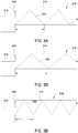
- FIGs. 3A-3C depict exemplary oscillation profiles 310, 320 and 330 of optical propagating modes, useful in understanding various embodiments such as the one described with respect to the embodiment of FIG. 2 .
- Mode oscillation profiles 310, 320 and 330 of the optical propagating mode are shown for illustrative purposes as occurring in waveguide 210 (of coupler 200), with offset 240 and offset and non-offset waveguide portions 212 and 214 respectively.
- Mode oscillation profiles 310, 320 and 330 are not drawn to any particular scale or with respect to any specific wavelengths, but are intended to be viewed in comparison to each other to illustrate the concept of how beat length changes with ⁇ relative to ⁇ d in waveguide structures such as waveguides 210 1-2 .
- Mode oscillation profile 310 depicts the path of the center energy of one or more modes laterally oscillating (due to offset 240) in a "zig-zag" pattern while propagating longitudinally along a non-offset waveguide portion 214 of a waveguide 210, to produce reduced wavelength sensitivity of the device (e.g., coupler 200) to which the waveguide is connected, according to various embodiments.
- the period of oscillation (T osc ) corresponds to beat length as defined by equations (3a) and (3b).
- mode oscillation profile 320 depicts an example of beat length (relative to mode oscillation profile 310) when ⁇ ⁇ ⁇ d .
- oscillating mode profile 330 illustrates an exemplary beat length according to ⁇ > ⁇ d , which is decreased relative to oscillation profile 310.
- the mode oscillation profiles discussed with respect to FIGs. 3A-3D may be adapted to influence response characteristics of devices according to various embodiments, such that wavelengths to which such devices are less sensitive to pass through the devices with little or no encumbrance, while wavelengths to which the device is more sensitive to are reduced or attenuated.
- Various embodiments impart mode oscillations using different structures and techniques, such as described herein in more detail.
- the mode oscillations are implemented in a manner adapted to the specific wavelength sensitivities of the device.
- the various equations discussed herein may be used to calculate the appropriate mode oscillation profile. Alternatively, the mode oscillation profile may be determined empirically.
- FIG. 3D depicts a coupler 340, similar to coupler 200, illustrating further details of how mode oscillation may be facilitated in the connection terminals of devices utilizing offsets such as offset 240 of FIG. 2 , to produce mode oscillation in the terminals (e.g., waveguides) and decrease wavelength sensitivity according to various embodiments.
- coupler 340 is a 90 degree, substantially wavelength insensitive 2x4 hybrid optical device, including input waveguides 210 1-2 , a free space region 220, output waveguides 230 1-4 , dummy waveguides 140, offsets 240 and respective offset portions 212 1-2 and non-offset portions 214 1-2 .
- a change in excitation wavelength ⁇ in the coupler 200 (and coupler 340) creates a shift of ⁇ 1 , providing wavelength insensitivity of the coupler(s) according to various embodiments.
- mode oscillations are implemented in a manner adapted to the specific wavelength sensitivities of the device.
- the various equations discussed herein may be used to calculate the appropriate mode oscillation profile.
- the appropriate mode oscillation profile may be determined empirically.
- FIGs. 2 and 3A-3D depict offsets 240 on the outer side of input waveguides 210 1-2 . That is, non-offset output portion 214 as an end positioned at the input boundary 222, between free space region 220 and offset portion 212.
- L b e.g., per equations 3a and/or 2b
- oscillation produced in the guided optical mode is adjustable. That is, oscillation profiles such as respective oscillation profiles 310, 320 and 330 of FIGs. 3A-3C are not based solely on the device's physical dimensions and material composition.
- a planar optical device such as coupler 200 is constructed on an Indium Phosphide (InP) semiconductor substrate with electrodes positioned along the length of a multi-mode waveguide (lead), such as 214 1-2 .
- a current is created in the guide changes the refractive index along its length.
- refractive index e.g., beat length
- the properties of the oscillation may be moved, and/or the coupler may be tuned.
Landscapes
- Physics & Mathematics (AREA)
- General Physics & Mathematics (AREA)
- Optics & Photonics (AREA)
- Engineering & Computer Science (AREA)
- Microelectronics & Electronic Packaging (AREA)
- Optical Integrated Circuits (AREA)
- Lasers (AREA)
- Semiconductor Lasers (AREA)
Claims (4)
- Dispositif optique (100, 200), comprenant :une zone optique en espace libre (120, 220) ;un ou plusieurs guides d'onde optiques d'entrée (110, 210) reliés à leur extrémité à la zone optique en espace libre (120, 220) le long d'une première surface de cette dernière ; etun ou plusieurs guides d'onde optiques de sortie (130, 230) reliés à leur extrémité à la zone optique en espace libre (120, 220) le long d'une deuxième surface de cette dernière, la deuxième surface faisant face à la première surface ;dans lequel l'ensemble des guides d'onde optiques d'entrée et de sortie (110, 210, 130, 230) inclut au moins trois guides d'onde optiques,dans lequel au moins l'un du ou des guides d'onde optiques d'entrée (210) prend en charge la propagation multimode et comporte un décalage (240) au niveau de la jonction des extrémités d'une partie d'entrée (212) et d'une partie de sortie (214) de ceux-ci, l'extrémité de la partie de sortie (214) étant reliée à la première surface ; etdans lequel le décalage (240) est adapté pour générer un mode d'oscillation dans le ou les guides d'onde optiques d'entrée de sorte que le mode d'oscillation se déplace transversalement selon un motif en zigzag le long d'une longueur du ou des guides d'onde optiques d'entrée.
- Dispositif optique selon la revendication 1, dans lequel la partie de sortie du ou des guides d'onde d'entrée (110, 210) a une longueur l exprimée par :
 nf = l'indice de réflexion du coeur du guide d'onde ;weff = une largeur effective du ou des guides d'onde optiques ;λd = une longueur d'onde télécom standard ; etA = un entier ≥ 0.
 - Dispositif optique selon la revendication 1, dans lequel le décalage a une dimension d'environ w eff /4 ± (0,1) weff /4, où weffl4 est la largeur du coeur du ou des guides d'onde d'entrée.
- Dispositif optique selon la revendication 1, dans lequel le dispositif optique est un coupleur en étoile.
Applications Claiming Priority (2)
| Application Number | Priority Date | Filing Date | Title |
|---|---|---|---|
| US12/268,705 US7876983B2 (en) | 2008-11-11 | 2008-11-11 | Method and apparatus for a wavelength insensitive 90-degree hybrid device |
| PCT/US2009/063984 WO2010056713A2 (fr) | 2008-11-11 | 2009-11-11 | Procédé et appareil pour dispositif hybride sensiblement insensible aux longueurs d'onde |
Publications (3)
| Publication Number | Publication Date |
|---|---|
| EP2356500A2 EP2356500A2 (fr) | 2011-08-17 |
| EP2356500A4 EP2356500A4 (fr) | 2012-05-30 |
| EP2356500B1 true EP2356500B1 (fr) | 2017-08-30 |
Family
ID=42165285
Family Applications (1)
| Application Number | Title | Priority Date | Filing Date |
|---|---|---|---|
| EP09826647.1A Not-in-force EP2356500B1 (fr) | 2008-11-11 | 2009-11-11 | Procédé et appareil pour dispositif hybride sensiblement insensible aux longueurs d'onde |
Country Status (6)
| Country | Link |
|---|---|
| US (1) | US7876983B2 (fr) |
| EP (1) | EP2356500B1 (fr) |
| JP (1) | JP5410541B2 (fr) |
| KR (1) | KR101313491B1 (fr) |
| CN (1) | CN102209922B (fr) |
| WO (1) | WO2010056713A2 (fr) |
Families Citing this family (6)
| Publication number | Priority date | Publication date | Assignee | Title |
|---|---|---|---|---|
| SE0850021L (sv) * | 2008-09-23 | 2009-12-29 | Syntune Ab | Vågledare för utkoppling med låg reflex. |
| CN104965258B (zh) * | 2015-07-22 | 2018-03-27 | 湖南晶图科技有限公司 | 一种功率均匀分配的星型耦合器及其设置方法 |
| CN106443882B (zh) * | 2016-11-29 | 2019-07-23 | 华中科技大学 | 一种硅基超材料光星形交叉连接器及其制备方法 |
| US11500154B1 (en) * | 2019-10-18 | 2022-11-15 | Apple Inc. | Asymmetric optical power splitting system and method |
| US11906778B2 (en) | 2020-09-25 | 2024-02-20 | Apple Inc. | Achromatic light splitting device with a high V number and a low V number waveguide |
| US11971574B2 (en) | 2021-09-24 | 2024-04-30 | Apple Inc. | Multi-mode devices for multiplexing and de-multiplexing |
Family Cites Families (17)
| Publication number | Priority date | Publication date | Assignee | Title |
|---|---|---|---|---|
| US4904042A (en) * | 1988-05-03 | 1990-02-27 | American Telephone And Telegraph Company | N×N optical star coupler |
| US5136671A (en) * | 1991-08-21 | 1992-08-04 | At&T Bell Laboratories | Optical switch, multiplexer, and demultiplexer |
| US5243672A (en) * | 1992-08-04 | 1993-09-07 | At&T Bell Laboratories | Planar waveguide having optimized bend |
| JP2817565B2 (ja) * | 1993-03-18 | 1998-10-30 | 日立電線株式会社 | 光スターカップラ |
| US5359687A (en) * | 1993-08-23 | 1994-10-25 | Alliedsignal Inc. | Polymer microstructures which facilitate fiber optic to waveguide coupling |
| US5706377A (en) * | 1996-07-17 | 1998-01-06 | Lucent Technologies Inc. | Wavelength routing device having wide and flat passbands |
| US6222955B1 (en) * | 1998-01-30 | 2001-04-24 | Jds Fitel Inc. | Integrated 1×N optical switch |
| GB2334594A (en) * | 1998-02-20 | 1999-08-25 | Fujitsu Telecommunications Eur | Arrayed waveguide grating device |
| CA2346130A1 (fr) * | 1998-11-10 | 2000-05-18 | Lightwave Microsystems Corporation | Dispositifs photoniques comprenant un polymere thermo-optique |
| US6385373B1 (en) * | 1999-10-29 | 2002-05-07 | Lucent Technologies Inc. | Compensated cascaded waveguides |
| US6289147B1 (en) * | 1999-11-01 | 2001-09-11 | Bbv Design Bv | Passband flattening of a phasar |
| JP2001318253A (ja) * | 2000-05-12 | 2001-11-16 | Furukawa Electric Co Ltd:The | 光導波路型方向性結合器およびこの光導波路型方向性結合器を用いた光導波回路 |
| EP1239311A1 (fr) * | 2001-03-05 | 2002-09-11 | Corning O.T.I. S.p.A. | Dispositif optique intégrée avec jonction adiabatique |
| KR100383586B1 (ko) | 2001-06-20 | 2003-05-14 | 삼성전자주식회사 | 옵셋을 이용한 와이-분기형 광도파로 |
| JP3543138B2 (ja) * | 2002-04-24 | 2004-07-14 | Tdk株式会社 | 光分岐回路及び装置 |
| EP1426799A3 (fr) * | 2002-11-29 | 2005-05-18 | Matsushita Electric Industrial Co., Ltd. | Démultiplexeur optique, multiplexeur/démultiplexeur optique, et dispositif optique |
| US7330618B2 (en) * | 2005-11-30 | 2008-02-12 | Lucent Technologies Inc. | Waveguide structure |
-
2008
- 2008-11-11 US US12/268,705 patent/US7876983B2/en not_active Expired - Fee Related
-
2009
- 2009-11-11 EP EP09826647.1A patent/EP2356500B1/fr not_active Not-in-force
- 2009-11-11 JP JP2011536434A patent/JP5410541B2/ja not_active Expired - Fee Related
- 2009-11-11 KR KR1020117010723A patent/KR101313491B1/ko not_active IP Right Cessation
- 2009-11-11 WO PCT/US2009/063984 patent/WO2010056713A2/fr active Application Filing
- 2009-11-11 CN CN200980144916.1A patent/CN102209922B/zh not_active Expired - Fee Related
Non-Patent Citations (1)
| Title |
|---|
| None * |
Also Published As
| Publication number | Publication date |
|---|---|
| JP5410541B2 (ja) | 2014-02-05 |
| US7876983B2 (en) | 2011-01-25 |
| EP2356500A4 (fr) | 2012-05-30 |
| JP2012508403A (ja) | 2012-04-05 |
| KR101313491B1 (ko) | 2013-10-01 |
| WO2010056713A3 (fr) | 2010-07-22 |
| EP2356500A2 (fr) | 2011-08-17 |
| WO2010056713A2 (fr) | 2010-05-20 |
| US20100119195A1 (en) | 2010-05-13 |
| CN102209922A (zh) | 2011-10-05 |
| KR20110067164A (ko) | 2011-06-21 |
| CN102209922B (zh) | 2014-01-15 |
Similar Documents
| Publication | Publication Date | Title |
|---|---|---|
| EP2356500B1 (fr) | Procédé et appareil pour dispositif hybride sensiblement insensible aux longueurs d'onde | |
| KR100739522B1 (ko) | 전자기파 주파수 필터 | |
| US7302137B2 (en) | Optical coupler apparatus and method | |
| Yasa et al. | High extinction ratio polarization beam splitter design by low-symmetric photonic crystals | |
| US20100322555A1 (en) | Grating Structures for Simultaneous Coupling to TE and TM Waveguide Modes | |
| Rawal et al. | Design, analysis and optimization of silicon-on-insulator photonic crystal dual band wavelength demultiplexer | |
| US7546014B2 (en) | Optical directional coupler | |
| JP2018514001A (ja) | 高インデックスコントラストのフォトニックデバイスおよびその応用 | |
| CN103238093A (zh) | 光分支元件、使用光分支元件的光波导设备,以及制造光分支元件的方法,制造光波导设备的方法 | |
| JP2006284791A (ja) | マルチモード干渉光カプラ | |
| Mou et al. | Ultrahigh Q SOI ring resonator with a strip waveguide | |
| Franchi et al. | The infinity-loop microresonator: A new integrated photonic structure working on an exceptional surface | |
| KR101023254B1 (ko) | 플라즈몬 투과 필터 | |
| US20050152649A1 (en) | Device for directional and wavelength-selective optical coupling | |
| WO2013124502A1 (fr) | Dispositif de couplage de guides d'onde et procédé de conception dudit dispositif | |
| JP2008065104A (ja) | マルチモード干渉光カプラ | |
| Lourenço et al. | Simulation analysis of a thin film semiconductor MMI 3dB splitter operating in the visible range | |
| Franchi | The taiji and infinity-loop microresonators: examples of non-Hermitian photonic systems | |
| US20150117809A1 (en) | Silicon waveguide having polarization insensitive and temperature insensitive phase delay | |
| Tsarev | Novel multi-splitting widely tunable filter on SOI technology | |
| JPH04346301A (ja) | 光合分岐器 | |
| Rizal et al. | Nanoscale Silicon Waveguide Based Thermo-Optic Sensor Using a Compact Mach-Zehnder Interferometer | |
| Gauthier et al. | 2D FDTD simulation of low loss small angle bend and Y branch configurations in a photonic crystal waveguide layout with a Mach–Zehnder device design configuration | |
| Sawada et al. | CMOS-compatible Si-wire polarization beam splitter based on wavelength-insensitive coupler | |
| Niraula et al. | 2x4 Hybrid MZI-MMI Configuration with MMI Phase-shifters as a High-speed Optical Switch with Low Power Consumption |
Legal Events
| Date | Code | Title | Description |
|---|---|---|---|
| PUAI | Public reference made under article 153(3) epc to a published international application that has entered the european phase |
Free format text: ORIGINAL CODE: 0009012 |
|
| 17P | Request for examination filed |
Effective date: 20110614 |
|
| AK | Designated contracting states |
Kind code of ref document: A2 Designated state(s): AT BE BG CH CY CZ DE DK EE ES FI FR GB GR HR HU IE IS IT LI LT LU LV MC MK MT NL NO PL PT RO SE SI SK SM TR |
|
| DAX | Request for extension of the european patent (deleted) | ||
| A4 | Supplementary search report drawn up and despatched |
Effective date: 20120427 |
|
| RIC1 | Information provided on ipc code assigned before grant |
Ipc: G02B 6/12 20060101ALI20120423BHEP Ipc: G02B 6/125 20060101ALI20120423BHEP Ipc: G02B 6/28 20060101AFI20120423BHEP |
|
| 111Z | Information provided on other rights and legal means of execution |
Free format text: AT BE BG CH CY CZ DE DK EE ES FI FR GB GR HR HU IE IS IT LI LT LU LV MC MK MT NL NO PL PT RO SE SI SK SM TR Effective date: 20130410 |
|
| 17Q | First examination report despatched |
Effective date: 20131011 |
|
| D11X | Information provided on other rights and legal means of execution (deleted) | ||
| GRAP | Despatch of communication of intention to grant a patent |
Free format text: ORIGINAL CODE: EPIDOSNIGR1 |
|
| INTG | Intention to grant announced |
Effective date: 20160715 |
|
| GRAJ | Information related to disapproval of communication of intention to grant by the applicant or resumption of examination proceedings by the epo deleted |
Free format text: ORIGINAL CODE: EPIDOSDIGR1 |
|
| INTC | Intention to grant announced (deleted) | ||
| GRAP | Despatch of communication of intention to grant a patent |
Free format text: ORIGINAL CODE: EPIDOSNIGR1 |
|
| INTG | Intention to grant announced |
Effective date: 20170105 |
|
| GRAJ | Information related to disapproval of communication of intention to grant by the applicant or resumption of examination proceedings by the epo deleted |
Free format text: ORIGINAL CODE: EPIDOSDIGR1 |
|
| INTC | Intention to grant announced (deleted) | ||
| GRAP | Despatch of communication of intention to grant a patent |
Free format text: ORIGINAL CODE: EPIDOSNIGR1 |
|
| INTG | Intention to grant announced |
Effective date: 20170330 |
|
| GRAS | Grant fee paid |
Free format text: ORIGINAL CODE: EPIDOSNIGR3 |
|
| GRAA | (expected) grant |
Free format text: ORIGINAL CODE: 0009210 |
|
| AK | Designated contracting states |
Kind code of ref document: B1 Designated state(s): AT BE BG CH CY CZ DE DK EE ES FI FR GB GR HR HU IE IS IT LI LT LU LV MC MK MT NL NO PL PT RO SE SI SK SM TR |
|
| REG | Reference to a national code |
Ref country code: GB Ref legal event code: FG4D |
|
| REG | Reference to a national code |
Ref country code: CH Ref legal event code: EP |
|
| REG | Reference to a national code |
Ref country code: AT Ref legal event code: REF Ref document number: 924108 Country of ref document: AT Kind code of ref document: T Effective date: 20170915 |
|
| REG | Reference to a national code |
Ref country code: IE Ref legal event code: FG4D |
|
| REG | Reference to a national code |
Ref country code: DE Ref legal event code: R096 Ref document number: 602009048099 Country of ref document: DE |
|
| REG | Reference to a national code |
Ref country code: FR Ref legal event code: PLFP Year of fee payment: 9 |
|
| REG | Reference to a national code |
Ref country code: NL Ref legal event code: MP Effective date: 20170830 |
|
| REG | Reference to a national code |
Ref country code: LT Ref legal event code: MG4D |
|
| REG | Reference to a national code |
Ref country code: AT Ref legal event code: MK05 Ref document number: 924108 Country of ref document: AT Kind code of ref document: T Effective date: 20170830 |
|
| PG25 | Lapsed in a contracting state [announced via postgrant information from national office to epo] |
Ref country code: SE Free format text: LAPSE BECAUSE OF FAILURE TO SUBMIT A TRANSLATION OF THE DESCRIPTION OR TO PAY THE FEE WITHIN THE PRESCRIBED TIME-LIMIT Effective date: 20170830 Ref country code: HR Free format text: LAPSE BECAUSE OF FAILURE TO SUBMIT A TRANSLATION OF THE DESCRIPTION OR TO PAY THE FEE WITHIN THE PRESCRIBED TIME-LIMIT Effective date: 20170830 Ref country code: LT Free format text: LAPSE BECAUSE OF FAILURE TO SUBMIT A TRANSLATION OF THE DESCRIPTION OR TO PAY THE FEE WITHIN THE PRESCRIBED TIME-LIMIT Effective date: 20170830 Ref country code: NO Free format text: LAPSE BECAUSE OF FAILURE TO SUBMIT A TRANSLATION OF THE DESCRIPTION OR TO PAY THE FEE WITHIN THE PRESCRIBED TIME-LIMIT Effective date: 20171130 Ref country code: AT Free format text: LAPSE BECAUSE OF FAILURE TO SUBMIT A TRANSLATION OF THE DESCRIPTION OR TO PAY THE FEE WITHIN THE PRESCRIBED TIME-LIMIT Effective date: 20170830 Ref country code: FI Free format text: LAPSE BECAUSE OF FAILURE TO SUBMIT A TRANSLATION OF THE DESCRIPTION OR TO PAY THE FEE WITHIN THE PRESCRIBED TIME-LIMIT Effective date: 20170830 |
|
| PG25 | Lapsed in a contracting state [announced via postgrant information from national office to epo] |
Ref country code: BG Free format text: LAPSE BECAUSE OF FAILURE TO SUBMIT A TRANSLATION OF THE DESCRIPTION OR TO PAY THE FEE WITHIN THE PRESCRIBED TIME-LIMIT Effective date: 20171130 Ref country code: LV Free format text: LAPSE BECAUSE OF FAILURE TO SUBMIT A TRANSLATION OF THE DESCRIPTION OR TO PAY THE FEE WITHIN THE PRESCRIBED TIME-LIMIT Effective date: 20170830 Ref country code: ES Free format text: LAPSE BECAUSE OF FAILURE TO SUBMIT A TRANSLATION OF THE DESCRIPTION OR TO PAY THE FEE WITHIN THE PRESCRIBED TIME-LIMIT Effective date: 20170830 Ref country code: GR Free format text: LAPSE BECAUSE OF FAILURE TO SUBMIT A TRANSLATION OF THE DESCRIPTION OR TO PAY THE FEE WITHIN THE PRESCRIBED TIME-LIMIT Effective date: 20171201 Ref country code: IS Free format text: LAPSE BECAUSE OF FAILURE TO SUBMIT A TRANSLATION OF THE DESCRIPTION OR TO PAY THE FEE WITHIN THE PRESCRIBED TIME-LIMIT Effective date: 20171230 |
|
| PG25 | Lapsed in a contracting state [announced via postgrant information from national office to epo] |
Ref country code: NL Free format text: LAPSE BECAUSE OF FAILURE TO SUBMIT A TRANSLATION OF THE DESCRIPTION OR TO PAY THE FEE WITHIN THE PRESCRIBED TIME-LIMIT Effective date: 20170830 |
|
| PG25 | Lapsed in a contracting state [announced via postgrant information from national office to epo] |
Ref country code: DK Free format text: LAPSE BECAUSE OF FAILURE TO SUBMIT A TRANSLATION OF THE DESCRIPTION OR TO PAY THE FEE WITHIN THE PRESCRIBED TIME-LIMIT Effective date: 20170830 Ref country code: RO Free format text: LAPSE BECAUSE OF FAILURE TO SUBMIT A TRANSLATION OF THE DESCRIPTION OR TO PAY THE FEE WITHIN THE PRESCRIBED TIME-LIMIT Effective date: 20170830 Ref country code: PL Free format text: LAPSE BECAUSE OF FAILURE TO SUBMIT A TRANSLATION OF THE DESCRIPTION OR TO PAY THE FEE WITHIN THE PRESCRIBED TIME-LIMIT Effective date: 20170830 Ref country code: CZ Free format text: LAPSE BECAUSE OF FAILURE TO SUBMIT A TRANSLATION OF THE DESCRIPTION OR TO PAY THE FEE WITHIN THE PRESCRIBED TIME-LIMIT Effective date: 20170830 |
|
| PG25 | Lapsed in a contracting state [announced via postgrant information from national office to epo] |
Ref country code: SK Free format text: LAPSE BECAUSE OF FAILURE TO SUBMIT A TRANSLATION OF THE DESCRIPTION OR TO PAY THE FEE WITHIN THE PRESCRIBED TIME-LIMIT Effective date: 20170830 Ref country code: IT Free format text: LAPSE BECAUSE OF FAILURE TO SUBMIT A TRANSLATION OF THE DESCRIPTION OR TO PAY THE FEE WITHIN THE PRESCRIBED TIME-LIMIT Effective date: 20170830 Ref country code: EE Free format text: LAPSE BECAUSE OF FAILURE TO SUBMIT A TRANSLATION OF THE DESCRIPTION OR TO PAY THE FEE WITHIN THE PRESCRIBED TIME-LIMIT Effective date: 20170830 Ref country code: SM Free format text: LAPSE BECAUSE OF FAILURE TO SUBMIT A TRANSLATION OF THE DESCRIPTION OR TO PAY THE FEE WITHIN THE PRESCRIBED TIME-LIMIT Effective date: 20170830 |
|
| REG | Reference to a national code |
Ref country code: DE Ref legal event code: R097 Ref document number: 602009048099 Country of ref document: DE |
|
| PG25 | Lapsed in a contracting state [announced via postgrant information from national office to epo] |
Ref country code: MC Free format text: LAPSE BECAUSE OF FAILURE TO SUBMIT A TRANSLATION OF THE DESCRIPTION OR TO PAY THE FEE WITHIN THE PRESCRIBED TIME-LIMIT Effective date: 20170830 |
|
| PLBE | No opposition filed within time limit |
Free format text: ORIGINAL CODE: 0009261 |
|
| STAA | Information on the status of an ep patent application or granted ep patent |
Free format text: STATUS: NO OPPOSITION FILED WITHIN TIME LIMIT |
|
| PG25 | Lapsed in a contracting state [announced via postgrant information from national office to epo] |
Ref country code: LI Free format text: LAPSE BECAUSE OF NON-PAYMENT OF DUE FEES Effective date: 20171130 Ref country code: CH Free format text: LAPSE BECAUSE OF NON-PAYMENT OF DUE FEES Effective date: 20171130 |
|
| 26N | No opposition filed |
Effective date: 20180531 |
|
| PG25 | Lapsed in a contracting state [announced via postgrant information from national office to epo] |
Ref country code: LU Free format text: LAPSE BECAUSE OF NON-PAYMENT OF DUE FEES Effective date: 20171111 Ref country code: SI Free format text: LAPSE BECAUSE OF FAILURE TO SUBMIT A TRANSLATION OF THE DESCRIPTION OR TO PAY THE FEE WITHIN THE PRESCRIBED TIME-LIMIT Effective date: 20170830 |
|
| REG | Reference to a national code |
Ref country code: BE Ref legal event code: MM Effective date: 20171130 |
|
| REG | Reference to a national code |
Ref country code: IE Ref legal event code: MM4A |
|
| PG25 | Lapsed in a contracting state [announced via postgrant information from national office to epo] |
Ref country code: MT Free format text: LAPSE BECAUSE OF NON-PAYMENT OF DUE FEES Effective date: 20171111 |
|
| REG | Reference to a national code |
Ref country code: FR Ref legal event code: PLFP Year of fee payment: 10 |
|
| PG25 | Lapsed in a contracting state [announced via postgrant information from national office to epo] |
Ref country code: IE Free format text: LAPSE BECAUSE OF NON-PAYMENT OF DUE FEES Effective date: 20171111 |
|
| PG25 | Lapsed in a contracting state [announced via postgrant information from national office to epo] |
Ref country code: BE Free format text: LAPSE BECAUSE OF NON-PAYMENT OF DUE FEES Effective date: 20171130 |
|
| PGFP | Annual fee paid to national office [announced via postgrant information from national office to epo] |
Ref country code: DE Payment date: 20181030 Year of fee payment: 10 |
|
| PGFP | Annual fee paid to national office [announced via postgrant information from national office to epo] |
Ref country code: GB Payment date: 20181107 Year of fee payment: 10 Ref country code: FR Payment date: 20181011 Year of fee payment: 10 |
|
| PG25 | Lapsed in a contracting state [announced via postgrant information from national office to epo] |
Ref country code: HU Free format text: LAPSE BECAUSE OF FAILURE TO SUBMIT A TRANSLATION OF THE DESCRIPTION OR TO PAY THE FEE WITHIN THE PRESCRIBED TIME-LIMIT; INVALID AB INITIO Effective date: 20091111 |
|
| PG25 | Lapsed in a contracting state [announced via postgrant information from national office to epo] |
Ref country code: CY Free format text: LAPSE BECAUSE OF NON-PAYMENT OF DUE FEES Effective date: 20170830 |
|
| PG25 | Lapsed in a contracting state [announced via postgrant information from national office to epo] |
Ref country code: MK Free format text: LAPSE BECAUSE OF FAILURE TO SUBMIT A TRANSLATION OF THE DESCRIPTION OR TO PAY THE FEE WITHIN THE PRESCRIBED TIME-LIMIT Effective date: 20170830 |
|
| PG25 | Lapsed in a contracting state [announced via postgrant information from national office to epo] |
Ref country code: TR Free format text: LAPSE BECAUSE OF FAILURE TO SUBMIT A TRANSLATION OF THE DESCRIPTION OR TO PAY THE FEE WITHIN THE PRESCRIBED TIME-LIMIT Effective date: 20170830 |
|
| PG25 | Lapsed in a contracting state [announced via postgrant information from national office to epo] |
Ref country code: PT Free format text: LAPSE BECAUSE OF FAILURE TO SUBMIT A TRANSLATION OF THE DESCRIPTION OR TO PAY THE FEE WITHIN THE PRESCRIBED TIME-LIMIT Effective date: 20170830 |
|
| REG | Reference to a national code |
Ref country code: DE Ref legal event code: R119 Ref document number: 602009048099 Country of ref document: DE |
|
| GBPC | Gb: european patent ceased through non-payment of renewal fee |
Effective date: 20191111 |
|
| PG25 | Lapsed in a contracting state [announced via postgrant information from national office to epo] |
Ref country code: DE Free format text: LAPSE BECAUSE OF NON-PAYMENT OF DUE FEES Effective date: 20200603 Ref country code: FR Free format text: LAPSE BECAUSE OF NON-PAYMENT OF DUE FEES Effective date: 20191130 Ref country code: GB Free format text: LAPSE BECAUSE OF NON-PAYMENT OF DUE FEES Effective date: 20191111 |