EP2354018A1 - Container structure for removal of vacuum pressure - Google Patents
Container structure for removal of vacuum pressure Download PDFInfo
- Publication number
- EP2354018A1 EP2354018A1 EP10190382A EP10190382A EP2354018A1 EP 2354018 A1 EP2354018 A1 EP 2354018A1 EP 10190382 A EP10190382 A EP 10190382A EP 10190382 A EP10190382 A EP 10190382A EP 2354018 A1 EP2354018 A1 EP 2354018A1
- Authority
- EP
- European Patent Office
- Prior art keywords
- container
- base
- panel
- pressure
- pressure panel
- Prior art date
- Legal status (The legal status is an assumption and is not a legal conclusion. Google has not performed a legal analysis and makes no representation as to the accuracy of the status listed.)
- Withdrawn
Links
Images


Classifications
-
- B—PERFORMING OPERATIONS; TRANSPORTING
- B65—CONVEYING; PACKING; STORING; HANDLING THIN OR FILAMENTARY MATERIAL
- B65D—CONTAINERS FOR STORAGE OR TRANSPORT OF ARTICLES OR MATERIALS, e.g. BAGS, BARRELS, BOTTLES, BOXES, CANS, CARTONS, CRATES, DRUMS, JARS, TANKS, HOPPERS, FORWARDING CONTAINERS; ACCESSORIES, CLOSURES, OR FITTINGS THEREFOR; PACKAGING ELEMENTS; PACKAGES
- B65D1/00—Containers having bodies formed in one piece, e.g. by casting metallic material, by moulding plastics, by blowing vitreous material, by throwing ceramic material, by moulding pulped fibrous material, by deep-drawing operations performed on sheet material
- B65D1/02—Bottles or similar containers with necks or like restricted apertures, designed for pouring contents
-
- B—PERFORMING OPERATIONS; TRANSPORTING
- B65—CONVEYING; PACKING; STORING; HANDLING THIN OR FILAMENTARY MATERIAL
- B65D—CONTAINERS FOR STORAGE OR TRANSPORT OF ARTICLES OR MATERIALS, e.g. BAGS, BARRELS, BOTTLES, BOXES, CANS, CARTONS, CRATES, DRUMS, JARS, TANKS, HOPPERS, FORWARDING CONTAINERS; ACCESSORIES, CLOSURES, OR FITTINGS THEREFOR; PACKAGING ELEMENTS; PACKAGES
- B65D79/00—Kinds or details of packages, not otherwise provided for
- B65D79/005—Packages having deformable parts for indicating or neutralizing internal pressure-variations by other means than venting
- B65D79/008—Packages having deformable parts for indicating or neutralizing internal pressure-variations by other means than venting the deformable part being located in a rigid or semi-rigid container, e.g. in bottles or jars
- B65D79/0081—Packages having deformable parts for indicating or neutralizing internal pressure-variations by other means than venting the deformable part being located in a rigid or semi-rigid container, e.g. in bottles or jars in the bottom part thereof
-
- B—PERFORMING OPERATIONS; TRANSPORTING
- B65—CONVEYING; PACKING; STORING; HANDLING THIN OR FILAMENTARY MATERIAL
- B65B—MACHINES, APPARATUS OR DEVICES FOR, OR METHODS OF, PACKAGING ARTICLES OR MATERIALS; UNPACKING
- B65B3/00—Packaging plastic material, semiliquids, liquids or mixed solids and liquids, in individual containers or receptacles, e.g. bags, sacks, boxes, cartons, cans, or jars
- B65B3/04—Methods of, or means for, filling the material into the containers or receptacles
-
- B—PERFORMING OPERATIONS; TRANSPORTING
- B65—CONVEYING; PACKING; STORING; HANDLING THIN OR FILAMENTARY MATERIAL
- B65D—CONTAINERS FOR STORAGE OR TRANSPORT OF ARTICLES OR MATERIALS, e.g. BAGS, BARRELS, BOTTLES, BOXES, CANS, CARTONS, CRATES, DRUMS, JARS, TANKS, HOPPERS, FORWARDING CONTAINERS; ACCESSORIES, CLOSURES, OR FITTINGS THEREFOR; PACKAGING ELEMENTS; PACKAGES
- B65D1/00—Containers having bodies formed in one piece, e.g. by casting metallic material, by moulding plastics, by blowing vitreous material, by throwing ceramic material, by moulding pulped fibrous material, by deep-drawing operations performed on sheet material
- B65D1/02—Bottles or similar containers with necks or like restricted apertures, designed for pouring contents
- B65D1/0223—Bottles or similar containers with necks or like restricted apertures, designed for pouring contents characterised by shape
- B65D1/0261—Bottom construction
- B65D1/0276—Bottom construction having a continuous contact surface, e.g. Champagne-type bottom
-
- B—PERFORMING OPERATIONS; TRANSPORTING
- B65—CONVEYING; PACKING; STORING; HANDLING THIN OR FILAMENTARY MATERIAL
- B65D—CONTAINERS FOR STORAGE OR TRANSPORT OF ARTICLES OR MATERIALS, e.g. BAGS, BARRELS, BOTTLES, BOXES, CANS, CARTONS, CRATES, DRUMS, JARS, TANKS, HOPPERS, FORWARDING CONTAINERS; ACCESSORIES, CLOSURES, OR FITTINGS THEREFOR; PACKAGING ELEMENTS; PACKAGES
- B65D1/00—Containers having bodies formed in one piece, e.g. by casting metallic material, by moulding plastics, by blowing vitreous material, by throwing ceramic material, by moulding pulped fibrous material, by deep-drawing operations performed on sheet material
- B65D1/12—Cans, casks, barrels, or drums
- B65D1/14—Cans, casks, barrels, or drums characterised by shape
-
- B—PERFORMING OPERATIONS; TRANSPORTING
- B65—CONVEYING; PACKING; STORING; HANDLING THIN OR FILAMENTARY MATERIAL
- B65D—CONTAINERS FOR STORAGE OR TRANSPORT OF ARTICLES OR MATERIALS, e.g. BAGS, BARRELS, BOTTLES, BOXES, CANS, CARTONS, CRATES, DRUMS, JARS, TANKS, HOPPERS, FORWARDING CONTAINERS; ACCESSORIES, CLOSURES, OR FITTINGS THEREFOR; PACKAGING ELEMENTS; PACKAGES
- B65D79/00—Kinds or details of packages, not otherwise provided for
-
- B—PERFORMING OPERATIONS; TRANSPORTING
- B29—WORKING OF PLASTICS; WORKING OF SUBSTANCES IN A PLASTIC STATE IN GENERAL
- B29C—SHAPING OR JOINING OF PLASTICS; SHAPING OF MATERIAL IN A PLASTIC STATE, NOT OTHERWISE PROVIDED FOR; AFTER-TREATMENT OF THE SHAPED PRODUCTS, e.g. REPAIRING
- B29C49/00—Blow-moulding, i.e. blowing a preform or parison to a desired shape within a mould; Apparatus therefor
- B29C49/42—Component parts, details or accessories; Auxiliary operations
- B29C49/4273—Auxiliary operations after the blow-moulding operation not otherwise provided for
- B29C49/4283—Deforming the finished article
-
- B—PERFORMING OPERATIONS; TRANSPORTING
- B65—CONVEYING; PACKING; STORING; HANDLING THIN OR FILAMENTARY MATERIAL
- B65B—MACHINES, APPARATUS OR DEVICES FOR, OR METHODS OF, PACKAGING ARTICLES OR MATERIALS; UNPACKING
- B65B61/00—Auxiliary devices, not otherwise provided for, for operating on sheets, blanks, webs, binding material, containers or packages
- B65B61/24—Auxiliary devices, not otherwise provided for, for operating on sheets, blanks, webs, binding material, containers or packages for shaping or reshaping completed packages
-
- B—PERFORMING OPERATIONS; TRANSPORTING
- B67—OPENING, CLOSING OR CLEANING BOTTLES, JARS OR SIMILAR CONTAINERS; LIQUID HANDLING
- B67C—CLEANING, FILLING WITH LIQUIDS OR SEMILIQUIDS, OR EMPTYING, OF BOTTLES, JARS, CANS, CASKS, BARRELS, OR SIMILAR CONTAINERS, NOT OTHERWISE PROVIDED FOR; FUNNELS
- B67C3/00—Bottling liquids or semiliquids; Filling jars or cans with liquids or semiliquids using bottling or like apparatus; Filling casks or barrels with liquids or semiliquids
- B67C3/02—Bottling liquids or semiliquids; Filling jars or cans with liquids or semiliquids using bottling or like apparatus
- B67C3/22—Details
- B67C2003/226—Additional process steps or apparatuses related to filling with hot liquids, e.g. after-treatment
Definitions
- This invention relates generally to a container structure that allows for the removal of vacuum pressure. This is achieved by inverting a transversely oriented vacuum pressure panel located in the lower end-wall, or base region of the container.
- So called 'hot fill' containers are well known in prior art, whereby manufacturers supply PET containers for various liquids which are filled into the containers and the liquid product is at an elevated temperature, typically at or around 85 degrees C (185 degrees F).
- the container is manufactured to withstand the thermal shock of holding a heated liquid, resulting in a 'heat-set' plastic container. This thermal shock is a result of either introducing the liquid hot at filling, or heating the liquid after it is introduced into the container.
- vacuum pressures have been accommodated by the use of vacuum panels, which distort inwardly under vacuum pressure.
- Prior art reveals many vertically oriented vacuum panels that allow containers to withstand the rigors of "hot fill procedure. Such vertically oriented vacuum panels generally lie parallel to the longitudinal axis of a container and flex inwardly under vacuum pressure toward this longitudinal axis.
- Silvers does provide for the base region to be strengthened by coupling it to the standing ring of the container, in order to assist preventing unwanted outward movement of the inwardly inclined or flat portion when a heated liquid builds up initial internal pressure in a newly filled and capped container.
- This coupling is achieved by rib structures, which also serve to strengthen the flat region. Whilst this may strengthen the region in order to allow more vacuum force to be applied to it, the ribs conversely further reduce flexibility within the base region, and therefore reduce flexibility.
- the present invention relates to a hot-fill container which is a development of the hot-fill container described in our international application WO 02/18213 (the PCT specification), which specification is incorporated herein in its entirety where appropriate.
- a semi-rigid container was provided that had a substantially vertically folding vacuum panel portion.
- Such a transversely oriented vacuum panel portion included an initiator portion and a control portion which generally resisted being expanded from the collapsed state.
- a further and alternative object of the present invention in all its embodiments, all the objects to be read disjunctively, is to at least provide the public with a useful choice.
- a container having a longitudinal axis, an upper portion having an opening into said container, a body portion extending from said upper portion to a lower portion, said lower portion including a base, said base closing off an end of said container, said container having at least, one substantially transversely oriented pressure panel portion located in said lower portion, said pressure panel portion being capable of folding from one longitudinally inclined position to an inverted position to compensate for a change of pressure induced within the container.
- a container has a longitudinal axis and a base, and at least one substantially transversely oriented vacuum panel portion located adjacent to said base, said vacuum panel portion being adapted in use to fold from a longitudinally inclined position to an inverted position to compensate for a change of pressure induced within the container following cooling of a liquid within the container after it has been capped, such that less force is exerted on the internal walls of said container.
- a container has a longitudinal axis, a side wall and a base closing off one end, said container having a single substantially transversely oriented vacuum panel portion located within the base and joined to the side wall by a decoupling or hinge structure, said vacuum panel portion being adapted in use to fold from a longitudinally inclined position to an inverted position to compensate for a change of pressure induced within the container.
- the vacuum panel portion may include an initiator section and a control section, said initiator section providing for folding before said control section.
- a decoupling structure connects the pressure panel portion with the body portion and is of an area which allows for greater inward and upward longitudinal movement of the pressure panel.
- the vacuum panel portion has no strengthening ribs to restrain substantial longitundinal movement and inversion.
- the vacuum panel portion may include fluting structures or the like to allow an even circumferential distribution of folding forces to provide for increased control over folding the panel portion from one inclined position to another and to assist in preventing unwanted return to the original position.
- the container standing support is provided by a lower part of the container sidewall that provides a replacement container standing support.
- a method of compensating for a change in pressure in a container as defined in any one of the preceding eight paragraphs includes applying a force to the or each said panel portion to cause said folding to occur.
- containers have typically been provided with a series of vacuum panels around their sidewalls and an optimized base portion.
- the vacuum panels deform inwardly, and the base deforms upwardly, under the influence of the vacuum forces. This prevents unwanted distortion elsewhere in the container.
- the container is still subjected to internal vacuum force.
- the panels and base merely provide a suitably resistant structure against that force. The more resistant the structure the more vacuum force will be present. Additionally, end users can feel the vacuum panels when holding the containers.
- the present invention relates to hot-fill containers and a structure that provides for the substantial removal or substantial negation of vacuum pressure. This allows much greater design freedom and light weighting opportunities as there is no longer any requirement for the structure to be resistant to vacuum forces which would otherwise mechanically distort the container.
- the hot-fill container of the PCT specification has positioned an outwardly inclined and transversely oriented vacuum panel between the lower portion of the side wall and the inwardly domed base region. In this position the container has poor stability, insofar as the base region is very narrow in diameter and does not allow for a good standing ring support.
- a decoupling structure that provides a hinge joint to the juncture of the vacuum panel and the lower sidewall. This decoupling structure provides for a larger range of longitudinal movement of the vacuum panel than would occur if the panel was coupled to the side wall by way of ribs for example.
- the decoupling structure therefore provides for increased deflection of the initiator portion, allowing increased movement of the panel portion longitudinally away from the previously outwardly inclined position, enabling the panel portion to fold inwardly relative to the container and upwardly relative to the initial base position.
- the lower sidewall is therefore subjected to lower force during such inversion. During this action, the base portion is translated longitudinally upward and into the container.
- the decoupling structure allows for the vacuum panel to now form part of the container base portion. This development has at least two important advantages.
- the transversely oriented vacuum panel is effectively completely removed from view as it is forced from an outward position to an inward position.
- any design or shape can now be utilized, without regard for integrity against vacuum forces found in other hot-fill packages.
- the decoupling structure provides for the panel to become displaced longitudinally so that there is no contact between any part of the panel or upwardly domed base portion with the contact surface below. A standing ring is then provided by the lower sidewall immediately adjacent the decoupling structure.
- the initiator portion by gaining greater control over the inverting motion and forces, it is possible to allow the initiator portion to share the same steep angle as the control portion. This allows for increased volume displacement during inversion and increased resistance to any reversion back to the original position.
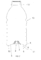
- Figure 1 shows, by way of example only, and in a diagrammatic cross sectional view, a container in the form of a bottle. This is referenced generally by arrow 10 with a typical neck portion 12 and a side wall 9 extending to a lower portion of the side wall 11 and an underneath base portion 2.
- the container 10 will typically be blow moulded from any suitable plastics material but typically this will be polyethylene terephthalate (PET).
- PET polyethylene terephthalate
- the base 2 is shown provided with a plurality of reinforcing ribs 3 so as to form the typical "champagne" base although this is merely by way of example only.
- FIG. 1 the lower side wall portion 11, which operates as a pressure panel, is shown in its unfolded position so that a ring or annular portion 6 is positioned above the level of the bottom of the base 2 which is forming the standing ring or support 4 for the container 10.
- an instep or recess 8 and decoupling structure 13 immediately adjacent the ring or annular portion 6 there may be an instep or recess 8 and decoupling structure 13, in this case a substantially flat, non-ribbed region, which after folding enables the base portion 2 to effectively completely disappear within the bottom of the container and above the line A-A.
- decoupling structure 13 Many other configurations for the decoupling structure 13 are envisioned, however.
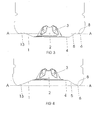
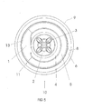
- the base 2 with its strengthening ribs 3 is shown surrounded by the bottom annular portion 11 of the side wall 9 and the annular structure 13.
- the bottom portion 11 is shown in this particular embodiment as having an initiator portion 1 which forms part of the collapsing or inverting section which yields to a longitudinally-directed collapsing force before the rest of the collapsing or folding section.
- the base 2 is shown provided within the typical base standing ring 4, which will be the first support position for the container 10 prior to the inversion of the folding panel.
- control portion 5 Associated with the initiator portion 1 is a control portion 5 which in this embodiment is a more steeply angled inverting section which will resist expanding from the collapsed state.
- the panel control portion 5 is generally set with an angle varying between 30 degrees and 45 degrees. It is preferable to ensure an angle is set above 10 degrees at least.
- the initiator portion 1 may in this embodiment have a lesser angle of perhaps at least 10 degrees less than the control portion.
- control portion 5 may be initially set to be outwardly inclined by approximately 35 degrees and will then provide an inversion and angle change of approximately 70 degrees.
- the initiator portion may in this example be 20 degrees.
- the initiator portion may be reconfigured so that control portion 18 would provide essentially a continuous conical area about the base 2.
- initiator portion 1 and the control portion 5 of the embodiment of the preceding figures will now be at a common angle, such that they form a uniformly inclined panel portion.
- initiator portion 1 may still be configured to provide the area of least resistance to inversion, such that although it shares the same angular extent as the control portion 18, it still provides an initial area of collapse or inversion.
- initiator portion 1 causes the pressure panel 11 to begin inversion from the widest diameter adjacent the decoupling structure 13.
- the container side walls 9 are 'glass-like' in construction in that there are no additional strengthening ribs or panels as might be typically found on a container, particularly if required to withstand the forces of vacuum pressure. Additional, however, structures may be added to the conical portions of the vacuum panel 11 in order to add further control over the inversion process.
- the conical portion of the vacuum panel 11 may be divided into fluted regions. Referring to Figures 8a and 9 especially, panel portions that are convex outwardly, and evenly distributed around the central axis create regions of greater angular set 19 and regions of lesser angular set 18, may provide for greater control over inversion of the panel. Such geometry provides increased resistance to reversion of the panel, and a more even distribution of forces when in the inverted position.
- Concave or inwardly directed fluting arrangements are also envisioned, in addition to outwardly directed flutes.
- Inwardly directed flutes offer less resistance to initial inverting forces, coupled with increased resistance to reverting back out to the original position. In this way they behave in much the same manner as ribs to prevent the panel being forced back out to the outwardly inclined position, but allow for hinge movement from the first outwardly inclined position to the inwardly inclined position.
- Such inwardly or outwardly directed flutes or projections function as ribs to increase the force required to invert the panel.
- the mechanical action applied to invert the panel will be sufficient to overcome any rib-strengthened panel, and when the mechanical action is removed the rib-strengthened panel, for example by strong flutes, will be very resistant to reversion to the original position if the container is dropped or shocked.
- the container may be blow moulded with the pressure panel 20 in the inwardly or upwardly inclined position.
- a force could be imposed on the folding panel 20 such as by means of a mechanical pusher 21 introduced through the neck region and forced downwardly in order to place the panel in the outwardly inclined position prior to use as a vacuum container for example, as shown in Figure 11d .
- a force could be imposed on the folding panel 20 such as by means of a mechanical pusher 22 or the creation of some relative movement of the bottle base relative to a punch or the like, in order to force the panel 20 from an outwardly inclined position to an inwardly inclined position.
- Any deformation whereby the bottle shape was distorted prior to inversion of the panel 20 would be removed as internal volume is forcibly reduced.
- the vacuum within the container is removed as the inversion of the panel 20 causes a rise in pressure. Such a rise in pressure reduces vacuum pressure until ambient pressure is reached or even a slightly positive pressure is achieved.
- the panel may be inverted in the manner shown in Figures 12a-d in order to provide a panel to accommodate internal force such as is found in pasteurization and the like. In such a way the panel will provide relief against the internal pressure generated and then be capable of accommodating the resulting vacuum force generated when the product cools down.
- the panel will be inverted from an upwardly inclined position Figures 11 a to 11 b to a downwardly inclined position as shown in Figures 12a-d , except that the mechanical action is not provided.
- the force is instead provided by the internal pressure of the contents.
- decoupling or hinge structures 13 may also be provided many different decoupling or hinge structures 13 without departing from the scope of the invention. With' particular reference to Figures 6 and 7 , it can be seen that the side of the decoupling structure 13 that is provided for the pressure panel 11 may be of an enlarged area to provide for increased longitudinal movement upwards into the container following inversion.
- the widest portions 30 of the pressure panel 11 may invert earlier than the narrower portions 31.
- the initiator portion may be constructed with this in mind, to allow for thinner material and so on, to provide for the panel 11 to begin inverting where it has the greater diameter, ahead of the narrower sections of the panel.
- the portion 30 of the panel which is radially set more distant from the central axis of the container inverts ahead of portion 31 to act as the initiator portion.
Abstract
Description
- This invention relates generally to a container structure that allows for the removal of vacuum pressure. This is achieved by inverting a transversely oriented vacuum pressure panel located in the lower end-wall, or base region of the container.
- So called 'hot fill' containers are well known in prior art, whereby manufacturers supply PET containers for various liquids which are filled into the containers and the liquid product is at an elevated temperature, typically at or around 85 degrees C (185 degrees F).
- The container is manufactured to withstand the thermal shock of holding a heated liquid, resulting in a 'heat-set' plastic container. This thermal shock is a result of either introducing the liquid hot at filling, or heating the liquid after it is introduced into the container.
- Once the liquid cools down in a capped container, however, the volume of the liquid in the container reduces, creating a vacuum within the container. This liquid shrinkage results in vacuum pressures that pull inwardly on the side and end walls of the container. This in turn leads to deformation in the walls of plastic bottles if they are not constructed rigidly enough to resist such force.
- Typically, vacuum pressures have been accommodated by the use of vacuum panels, which distort inwardly under vacuum pressure. Prior art reveals many vertically oriented vacuum panels that allow containers to withstand the rigors of "hot fill procedure. Such vertically oriented vacuum panels generally lie parallel to the longitudinal axis of a container and flex inwardly under vacuum pressure toward this longitudinal axis.
- In addition to the vertically oriented vacuum panels, many prior art containers also have flexible base regions to provide additional vacuum compensation. Many prior art containers designed for hot-filling have various modifications to their end-walls, or base regions to allow for as much inward flexure as possible to accommodate at least some of the vacuum pressure generated within the container.
- All such prior art, however, provides for flat or inwardly inclined, or recessed base surfaces. These have been modified to be susceptible to as much further inward deflection as possible. As the base region yields to the force, it is drawn into a more inclined position than prior to having vacuum force applied.
- Unfortunately, however, the force generated under vacuum to pull longitudinally on the base region is only half that force generated in the transverse direction at the same time. Therefore, vertically oriented vacuum panels are able to react to force more easily than a panel placed in the base. Further, there is a lot more surface area available around the circumference of a container than in the end-wall. Therefore, adequate vacuum compensation can only be achieved by placing vertically-oriented vacuum panels over a substantial portion of the circumferential wall area of a container, typically 60% of the available area.
- Even with such substantial displacement of vertically-oriented panels, however, the container requires further strengthening to prevent distortion under the vacuum force.
- The liquid shrinkage derived from liquid cooling, causes a build up of vacuum pressure. Vacuum panels deflect toward this negative pressure, to a degree lessening the vacuum force, by effectively creating a smaller container to better accommodate the smaller volume of contents. However, this smaller shape is held in place by the generating vacuum force. The more difficult the structure is to deflect inwardly, the more vacuum force will be generated. In prior art, a substantial amount of vacuum is still present in the container and this tends to distort the overall shape unless a large, annular strengthening ring is provided in horizontal, or transverse, orientation at least a 1/3 of the distance from an end to the container.
- Considering this, it has become accepted knowledge to believe that it is impossible to provide for full vacuum compensation through modification to the end-wall or base region alone. The base region offers very little surface area, compared to the side walls, and reacts to force at half the rate of the side walls.
- Therefore it has become accepted practice to only expect partial assistance to the overall vacuum compensation to be generated through the base area. Further, even if the base region could provide for enough flexure to accommodate all liquid shrinkage within the container, there would be a significant vacuum force present, and significant stress on the base standing ring. This would place force on the sidewalls also, and to prevent distortion the smooth sidewalls would have to be much thicker in material distribution, be strengthened by ribbing or the like, or be placed into shapes more compatible to mechanical distortion (for example be square instead of circular).
- For this reason it has not been possible to provide container designs in plastic that do not have typical prior art vacuum panels that are vertically oriented on the sidewall. Many manufacturers have therefore been unable to commercialize plastic designs that are the same as their glass bottle designs with smooth sidewalls.
-
US Pat 6,595,380 (Silvers ), claims to provide for full vacuum compensation through the base region without requiring positioning of vertically oriented vacuum panels on the smooth sidewalls. This is suggested by combining techniques well-known and practiced in the prior art. Silvers provides for a slightly inwardly domed, and recessed base region to provide further inward movement under vacuum pressure. However, the technique disclosed, and the stated percentage areas required for efficiency are not considered by the present applicant to provide a viable solution to the problem. - In fact, flexure in the base region is recognised to be greatest in a horizontally flat base region, and maximizing such flat portions on the base has been well practiced and found to be unable to provide enough vacuum compensation to avoid also employing vertically oriented vacuum panels.
- Silvers does provide for the base region to be strengthened by coupling it to the standing ring of the container, in order to assist preventing unwanted outward movement of the inwardly inclined or flat portion when a heated liquid builds up initial internal pressure in a newly filled and capped container. This coupling is achieved by rib structures, which also serve to strengthen the flat region. Whilst this may strengthen the region in order to allow more vacuum force to be applied to it, the ribs conversely further reduce flexibility within the base region, and therefore reduce flexibility.
- It is believed by the present applicant that the specific 'ribbed' method proposed by Silvers could only provide for approximately 35% of the vacuum compensation that is required, as the modified end-wall is not considered capable of sufficient inward flexure to fully account for the liquid shrinkage that would occur. Therefore a strong maintenance of vacuum pressure is expected to occur. Containers employing such base structure therefore still require significant thickening of the sidewalls, and as this is done the base region also becomes thicker during manufacturing. The result is a less flexible base region, which in turn also reduces the efficiency of the vacuum compensation achieved.
- The present invention relates to a hot-fill container which is a development of the hot-fill container described in our international application
WO 02/18213 - The PCT specification backgrounds the design of hot-fill containers and the problems with such designs which were overcome or at least ameliorated by the design disclosed in the PCT specification.
- In the PCT specification a semi-rigid container was provided that had a substantially vertically folding vacuum panel portion. Such a transversely oriented vacuum panel portion included an initiator portion and a control portion which generally resisted being expanded from the collapsed state.
- Further described in the PCT specification is the inclusion of the vacuum panels at various positions along the container wall.
- A problem exists when locating such a panel in the end-wall or base region, whereby stability may be compromised if the panel does not move far enough into the container longitudinally to no longer form part of the container touching the surface the container stands on.
- A further problem exists when utilizing a transverse panel in the base end-wall due to the potential for shock deflection of the inverted panel when a full and capped container is dropped. This may occur on a container with soft and unstructured walls that is dropped directly on its side. The shock deflection of the sidewalls causes a shock-wave of internal pressure that acts on the panel. In such cases improved panel configurations are desired that further prevent panel roll-out, or initiator region configurations utilized that optimize for resistance to such reversion displacement.
- In view of the above, it is an object of one preferred embodiment of the present invention to provide a plastic container structure having a transversely oriented pressure panel in its lower portion that can provide for removal of vacuum pressure such that there is substantially no remaining force within the container.
- It is a further object of one preferred embodiment of the present invention to provide a container which has a transversely oriented pressure panel that is decoupled to a degree from the adjoining wall such that greater inward and longitudinal movement can be achieved.
- It is a further object of one preferred embodiment of the present invention to provide for a container to have a transversely oriented pressure panel that is inwardly displaced to a position above the standing ring of the final container configuration, such that a new base region is formed with a greater standing ring or foot print area, and the pressure panel is substantially protected from top load force applied to the container during commercial distribution.
- It is a further object of one preferred embodiment of the present invention to provide for an improved transversely oriented pressure panel having an initiator portion which may utilize essentially the same angle as the control portion, such that greater removal of vacuum pressure can be obtained and such that greater resistance to outward deflection can also be obtained.
- A further and alternative object of the present invention in all its embodiments, all the objects to be read disjunctively, is to at least provide the public with a useful choice.
- According to one aspect of the present invention there is provided a container having a longitudinal axis, an upper portion having an opening into said container, a body portion extending from said upper portion to a lower portion, said lower portion including a base, said base closing off an end of said container, said container having at least, one substantially transversely oriented pressure panel portion located in said lower portion, said pressure panel portion being capable of folding from one longitudinally inclined position to an inverted position to compensate for a change of pressure induced within the container.
- According to a further aspect of the present invention a container has a longitudinal axis and a base, and at least one substantially transversely oriented vacuum panel portion located adjacent to said base, said vacuum panel portion being adapted in use to fold from a longitudinally inclined position to an inverted position to compensate for a change of pressure induced within the container following cooling of a liquid within the container after it has been capped, such that less force is exerted on the internal walls of said container.
- According to a further aspect of the present invention a container has a longitudinal axis, a side wall and a base closing off one end, said container having a single substantially transversely oriented vacuum panel portion located within the base and joined to the side wall by a decoupling or hinge structure, said vacuum panel portion being adapted in use to fold from a longitudinally inclined position to an inverted position to compensate for a change of pressure induced within the container.
- Preferably in one embodiment the vacuum panel portion may include an initiator section and a control section, said initiator section providing for folding before said control section.
- Preferably in one embodiment a decoupling structure connects the pressure panel portion with the body portion and is of an area which allows for greater inward and upward longitudinal movement of the pressure panel.
- Preferably in one embodiment the vacuum panel portion has no strengthening ribs to restrain substantial longitundinal movement and inversion.
- Preferably in one embodiment the vacuum panel portion may include fluting structures or the like to allow an even circumferential distribution of folding forces to provide for increased control over folding the panel portion from one inclined position to another and to assist in preventing unwanted return to the original position.
- Preferably in one embodiment after folding, the container standing support is provided by a lower part of the container sidewall that provides a replacement container standing support.
- According to a further aspect of the invention a method of compensating for a change in pressure in a container as defined in any one of the preceding eight paragraphs is provided in which said method includes applying a force to the or each said panel portion to cause said folding to occur.
- According to a further aspect of this invention there is provided a hot-fill container substantially as herein described with reference to any one of the embodiments of the accompanying drawings.
- Further aspects of the invention which should be considered in all its novel aspects will become apparent from the following description.
-
- Figure 1:
- shows a cross-sectional view of a hot-fill container according to one possible embodiment of the invention in its pre-collapsed condition;
- Figure 2:
- shows the container of
Figure 1 in its collapsed position; - Figure 3:
- shows the base of
Figure 1 before collapsing; - Figure 4:
- shows the base of
Figure 2 following collapsing; - Figure 5:
- shows an underneath view of the base of the container of
Figure 1 before collapsing. - Figure 6:
- shows the base of
Figure 1 before collapsing; - Figure 7:
- shows the base of
Figure 2 following collapsing; - Figure 8a:
- shows a cross-sectional view of a hot-fill container according to an alternative embodiment of the invention in its pre-collapsed condition;
- Figure 8b:
- shows a cross-sectional view of the container shown in
Figures 8b and9 through line C-C - Figure 9:
- shows an underneath view of the base of the container of
Figures 8a and 8b andFigure 10 before collapsing - Figure 10:
- shows a cross-sectional view of the container shown in
Fig 9 through line D-D - Figures 11a-d:
- show cross-sectional views of the container according to an alternative embodiment of the invention incorporating a pusher to provide panel folding
- Figures 12a-d:
- show cross-sectional views of the container according to a further alternative embodiment of the invention incorporating a pusher to provide panel folding
- Figure 13:
- shows the base of an alternative embodiment of the invention before collapsing;
- Figure 14:
- shows the base of
Figure 13 during the initial stages of collapsing; - Figures 15a-b:
- show side and cross-sectional views of the container shown in
Fig 9 including outwardly projecting fluting; - Figure 15c:
- shows an underneath view of the base of the container of
Figures 15a and 15b with dotted contour section lines through lines E-E and F-F; - Figure 15d:
- shows a perspective view of the base of the container of
Figures15a-c ; - Figures 16a:
- shows a side view of a container of
Figure 16c according to an alternative embodiment including inwardly projecting fluting through Line I-I; - Figure 16b:
- shows a cross-sectional view of the base of the container of
Figure 16c through Line J-J; - Figure 16c:
- shows an underneath view of the base of the container of
Figures 16a and 16b with dotted contour section lines through lines G-G and H-H; - Figure 16d:
- shows a perspective view of the base of the container of
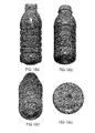
Figures 16a-c ; - Figures 17a-d:
- show side, side perspective, end perspective and end views respectively of the container of
Figures 15 . - Figures 18a-d:
- show side, side perspective, end perspective and end views respectively of the container of
Figures 16 . - The following description of preferred embodiments is merely exemplary in nature, and is in no way intended to limit the invention or its application or uses.
- As discussed above, to accommodate vacuum forces during cooling of the contents within a heat set container, containers have typically been provided with a series of vacuum panels around their sidewalls and an optimized base portion. The vacuum panels deform inwardly, and the base deforms upwardly, under the influence of the vacuum forces. This prevents unwanted distortion elsewhere in the container. However, the container is still subjected to internal vacuum force. The panels and base merely provide a suitably resistant structure against that force. The more resistant the structure the more vacuum force will be present. Additionally, end users can feel the vacuum panels when holding the containers.
- Typically at a bottling plant the containers will be filled with a hot liquid and then capped before being subjected to a cold water spray resulting in the formation of a vacuum within the container which the container structure needs to be able to cope with. The present invention relates to hot-fill containers and a structure that provides for the substantial removal or substantial negation of vacuum pressure. This allows much greater design freedom and light weighting opportunities as there is no longer any requirement for the structure to be resistant to vacuum forces which would otherwise mechanically distort the container.
- As mentioned above and in the PCT specification, various proposals for hot-fill container designs have been put forward.
- Further development of the hot-fill container of the PCT specification has positioned an outwardly inclined and transversely oriented vacuum panel between the lower portion of the side wall and the inwardly domed base region. In this position the container has poor stability, insofar as the base region is very narrow in diameter and does not allow for a good standing ring support. Additionally, there is preferably provided a decoupling structure that provides a hinge joint to the juncture of the vacuum panel and the lower sidewall. This decoupling structure provides for a larger range of longitudinal movement of the vacuum panel than would occur if the panel was coupled to the side wall by way of ribs for example. One side of the decoupling structure remains adjacent the sidewall, allowing the opposite side of the decoupling structure adjacent to an initiator portion to bend inwardly and upwardly. The decoupling structure therefore provides for increased deflection of the initiator portion, allowing increased movement of the panel portion longitudinally away from the previously outwardly inclined position, enabling the panel portion to fold inwardly relative to the container and upwardly relative to the initial base position. The lower sidewall is therefore subjected to lower force during such inversion. During this action, the base portion is translated longitudinally upward and into the container.
- Further, as the panel portion folds inwardly and upwardly, the decoupling structure allows for the vacuum panel to now form part of the container base portion. This development has at least two important advantages.
- Firstly, by providing the vacuum panel so as to form part of the base after folding, a mechanical force can now be provided immediately against the panel in order to apply inverting force. This allows much greater control over the action, which may for example be applied by a mechanical pusher, which would engage with the container base in resetting the container shape. This allows increased design options for the initiator portion.
- Secondly, the transversely oriented vacuum panel is effectively completely removed from view as it is forced from an outward position to an inward position. This means that there are no visible design features being imposed on the major portion of the side wall of the container in order to incorporate vacuum compensation. If required therefore, the major portion of the side wall of the present invention could have no structural features and the container could, if required, replicate a clear wall glass container. Alternatively, as there will be little or no vacuum remaining in the container after the panel is inverted, any design or shape can now be utilized, without regard for integrity against vacuum forces found in other hot-fill packages.
- Such a manoeuvre allows for a wide standing ring to be obtained. The decoupling structure provides for the panel to become displaced longitudinally so that there is no contact between any part of the panel or upwardly domed base portion with the contact surface below. A standing ring is then provided by the lower sidewall immediately adjacent the decoupling structure.
- Further, by gaining greater control over the inverting motion and forces, it is possible to allow the initiator portion to share the same steep angle as the control portion. This allows for increased volume displacement during inversion and increased resistance to any reversion back to the original position.
- Referring to the accompanying drawings,
Figure 1 shows, by way of example only, and in a diagrammatic cross sectional view, a container in the form of a bottle. This is referenced generally byarrow 10 with atypical neck portion 12 and aside wall 9 extending to a lower portion of theside wall 11 and an underneathbase portion 2. - The
container 10 will typically be blow moulded from any suitable plastics material but typically this will be polyethylene terephthalate (PET). - The
base 2 is shown provided with a plurality of reinforcingribs 3 so as to form the typical "champagne" base although this is merely by way of example only. - In
Figure 1 the lowerside wall portion 11, which operates as a pressure panel, is shown in its unfolded position so that a ring orannular portion 6 is positioned above the level of the bottom of thebase 2 which is forming the standing ring orsupport 4 for thecontainer 10. - In
Figure 2 the lowerside wall portion 11 is shown having folded inwardly so that the ring orannular portion 6 is positioned below the level of the bottom of thebase 2 and is forming the new standing ring or support for thecontainer 10. - To assist this occurring, and as will be seen particularly in
Figures 3 and 4 , immediately adjacent the ring orannular portion 6 there may be an instep orrecess 8 anddecoupling structure 13, in this case a substantially flat, non-ribbed region, which after folding enables thebase portion 2 to effectively completely disappear within the bottom of the container and above the line A-A. Many other configurations for thedecoupling structure 13 are envisioned, however. - Referring now particularly to
Figure 5 , thebase 2 with its strengtheningribs 3 is shown surrounded by the bottomannular portion 11 of theside wall 9 and theannular structure 13. Thebottom portion 11 is shown in this particular embodiment as having aninitiator portion 1 which forms part of the collapsing or inverting section which yields to a longitudinally-directed collapsing force before the rest of the collapsing or folding section. Thebase 2 is shown provided within the typicalbase standing ring 4, which will be the first support position for thecontainer 10 prior to the inversion of the folding panel. - Associated with the
initiator portion 1 is acontrol portion 5 which in this embodiment is a more steeply angled inverting section which will resist expanding from the collapsed state. - Forming the outer perimeter of the
bottom portion 11 of theside wall 9 is shown the side wall standing ring orannular portion 6 which following collapsing of thepanel 11 will provide the new container support. - To allow for increased evacuation of vacuum it will be appreciated that it is preferable to provide a steep angle to the
control portion 5 of thepressure panel 11. As shown inFigure 6 thepanel control portion 5 is generally set with an angle varying between 30 degrees and 45 degrees. It is preferable to ensure an angle is set above 10 degrees at least. Theinitiator portion 1 may in this embodiment have a lesser angle of perhaps at least 10 degrees less than the control portion. - By way of example, it will be appreciated that when the
panel 11 is inverted by mechanical compression it will undergo an angular change that is double that provided to it. If theconical control portion 5 is set to 10 degrees it will provide a panel change equivalent to 20 degrees. At such a low angle it has been found to provide an inadequate amount of vacuum compensation in a hot-filled container. Therefore it is preferable to provide much steeper angles. - Referring to
Figures 6 and 7 , it will be appreciated that thecontrol portion 5 may be initially set to be outwardly inclined by approximately 35 degrees and will then provide an inversion and angle change of approximately 70 degrees. The initiator portion may in this example be 20 degrees. - Referring to
Figures 8a and 8b , where the same reference numerals have been used where appropriate as previously, it is envisaged that in possible embodiments of this invention the initiator portion may be reconfigured so thatcontrol portion 18 would provide essentially a continuous conical area about thebase 2. - The
initiator portion 1 and thecontrol portion 5 of the embodiment of the preceding figures will now be at a common angle, such that they form a uniformly inclined panel portion. However,initiator portion 1 may still be configured to provide the area of least resistance to inversion, such that although it shares the same angular extent as thecontrol portion 18, it still provides an initial area of collapse or inversion. In this embodiment,initiator portion 1 causes thepressure panel 11 to begin inversion from the widest diameter adjacent thedecoupling structure 13. - In this embodiment the
container side walls 9 are 'glass-like' in construction in that there are no additional strengthening ribs or panels as might be typically found on a container, particularly if required to withstand the forces of vacuum pressure. Additional, however, structures may be added to the conical portions of thevacuum panel 11 in order to add further control over the inversion process. For example, the conical portion of thevacuum panel 11 may be divided into fluted regions. Referring toFigures 8a and9 especially, panel portions that are convex outwardly, and evenly distributed around the central axis create regions of greater angular set 19 and regions of lesserangular set 18, may provide for greater control over inversion of the panel. Such geometry provides increased resistance to reversion of the panel, and a more even distribution of forces when in the inverted position. - Referring to
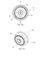
Figures 15a-c and17a-d , convex or downwardly outwardly projecting flutes are shown. - Concave or inwardly directed fluting arrangements are also envisioned, in addition to outwardly directed flutes. Inwardly directed flutes offer less resistance to initial inverting forces, coupled with increased resistance to reverting back out to the original position. In this way they behave in much the same manner as ribs to prevent the panel being forced back out to the outwardly inclined position, but allow for hinge movement from the first outwardly inclined position to the inwardly inclined position. Such inwardly or outwardly directed flutes or projections function as ribs to increase the force required to invert the panel. It will be appreciated that the mechanical action applied to invert the panel will be sufficient to overcome any rib-strengthened panel, and when the mechanical action is removed the rib-strengthened panel, for example by strong flutes, will be very resistant to reversion to the original position if the container is dropped or shocked.
- Referring to
Figures 16a-d and18a-d , concave or upwardly inwardly projecting flutes are shown, the contour lines G and H ofFigure 16c illustrating this concavity through two cross-sectional reliefs. - Further embodiments comprising arrays utilizing both concave and convex flutes are also intended within the scope of the invention.
- In the embodiment as shown in
Figures 11a-d , the container may be blow moulded with thepressure panel 20 in the inwardly or upwardly inclined position. A force could be imposed on thefolding panel 20 such as by means of amechanical pusher 21 introduced through the neck region and forced downwardly in order to place the panel in the outwardly inclined position prior to use as a vacuum container for example, as shown inFigure 11d . - In such an embodiment as shown in
Figures 12a-d , following the filling and capping of the bottle and the use of cold water spray creating the vacuum within the filled bottle, a force could be imposed on thefolding panel 20 such as by means of amechanical pusher 22 or the creation of some relative movement of the bottle base relative to a punch or the like, in order to force thepanel 20 from an outwardly inclined position to an inwardly inclined position. Any deformation whereby the bottle shape was distorted prior to inversion of thepanel 20 would be removed as internal volume is forcibly reduced. The vacuum within the container is removed as the inversion of thepanel 20 causes a rise in pressure. Such a rise in pressure reduces vacuum pressure until ambient pressure is reached or even a slightly positive pressure is achieved. - It will be appreciate that in a further embodiment of the invention the panel may be inverted in the manner shown in
Figures 12a-d in order to provide a panel to accommodate internal force such as is found in pasteurization and the like. In such a way the panel will provide relief against the internal pressure generated and then be capable of accommodating the resulting vacuum force generated when the product cools down. - In this way, the panel will be inverted from an upwardly inclined position
Figures 11 a to 11 b to a downwardly inclined position as shown inFigures 12a-d , except that the mechanical action is not provided. The force is instead provided by the internal pressure of the contents. - Referring again to
Figures 12a-d it will be seen that by the provision of thefolding portion 20 in the bottom of theside wall 9 of thecontainer 10 the major portion of theside wall 9 could be absent any structural features so that thecontainer 10 could essentially replicate a glass container if this was required. - Although particular structures for the bottom portion of the
side wall 9 are shown in the accompanying drawings it will be appreciated that alternative structures could be provided. For example a plurality of folding portions could be incorporated about thebase 2 in an alternative embodiment. - There may also be provided many different decoupling or hinge
structures 13 without departing from the scope of the invention. With' particular reference toFigures 6 and 7 , it can be seen that the side of thedecoupling structure 13 that is provided for thepressure panel 11 may be of an enlarged area to provide for increased longitudinal movement upwards into the container following inversion. - In a further embodiment of the present invention, and referring to
Figures 13 and 14 , it can be seen that thewidest portions 30 of thepressure panel 11 may invert earlier than thenarrower portions 31. The initiator portion may be constructed with this in mind, to allow for thinner material and so on, to provide for thepanel 11 to begin inverting where it has the greater diameter, ahead of the narrower sections of the panel. In this case theportion 30 of the panel, which is radially set more distant from the central axis of the container inverts ahead ofportion 31 to act as the initiator portion. - Where in the foregoing description, reference has been made to specific components or integers of the invention having known equivalents then such equivalents are herein incorporated as if individually set forth.
- Although this invention has been described by way of example and with reference to possible embodiments thereof, it is to be understood that modifications or improvements may be made thereto without departing from the scope of the invention as defined in the appended claims.
- The following numbered paragraphs (paras.) contain statements of broad combinations of the inventive technical features herein disclosed:-
- 1. A container having a longitudinal axis, an upper portion having an opening into said container, a body portion extending from said upper portion to a lower portion, said lower portion including a base, said base closing off an end of said container, said container having at least one substantially transversely oriented pressure panel portion located in said lower portion, said pressure panel portion being capable of folding from one longitudinally inclined position to an inverted position to compensate for a change of pressure induced within the container.
- 2. A container as claimed in para. 1 wherein said pressure panel portion is adapted to resist being expanded from the inverted position.
- 3. A container as claimed in para. 1 wherein said pressure panel portion includes an initiator portion and a control portion, said initiator portion providing for folding before said control portion.
- 4. A container as claimed in para. 3 wherein said control portion has a more acute angle than the initiator portion relative to the longitudinal axis of the container and wherein the initiator portion causes said control portion to invert and flex further inwardly into the container.
- 5. A container as claimed in para. 1 wherein said pressure panel portion provides compensation of vacuum pressure induced, in use, within the container following cooling of a heated liquid within the container after it has been capped, such that there remains substantially no vacuum pressure inside the container.
- 6. A container as claimed in para. 5 wherein said pressure panel portion is adapted in use to invert longitudinally under an externally applied mechanical force.
- 7. A container as claimed in para. 1 wherein said pressure panel portion is located immediately adjacent said base.
- 8. A container as claimed in para. 1 wherein said pressure panel portion is of variable width and inverts from its widest portion to its narrowest portion.
- 9. A container as claimed in para. 3 wherein said initiator section has an angular inclination relative to said longitudinal axis which is substantially the same as that of the control section.
- 10. A container as claimed in para. 1 wherein said pressure panel portion is adapted to cause said base to retract longitudinally into said body portion.
- 11. A container as claimed in para. 10 wherein said pressure panel portion is adapted to cause said lower portion of said body portion to replace said base portion in providing a standing support for the container.
- 12. A container as claimed in para. 11 wherein its structure is such that in use a top load applied to the container is transferred from said base to a portion of a sidewall of the container.
- 13. A container as claimed in para. 1 wherein said pressure panel portion is connected with said lower portion by a decoupling or hinge structure.
- 14. A container as claimed in para. 1 wherein said pressure panel portion includes outwardly projecting portions.
- 15. A container as claimed in para. 1 wherein said pressure panel portion includes inwardly projecting portions.
- 16. A container as claimed in para. 1 wherein said pressure panel portion is adapted in use to remove vacuum induced, in use, in the container such that substantially no vacuum remains.
- 17. A container as claimed in para. 3 wherein said control portion is outwardly inclined at an angle of more than 10° relative to a plane orthogonal to said longitudinal axis.
- 18. A container as claimed in para. 17 wherein said angle is between 30° and 45° and the angle of the initiator portion is at least 10° less.
- 19. A container as claimed in para. 1 wherein said pressure panel portion is included in said base.
- 20. A container as claimed in para. 1 having a single said transversely oriented pressure panel portion located in said lower portion.
- 21. A container as claimed in para. 1 wherein said pressure panel portion is adapted in use to provide compensation for internal pressure induced within the container following heating of a liquid within said container after it has been capped.
- 22. A container as claimed in para. 21 wherein said pressure panel portion is adapted in use to subsequently provide compensation for reduced pressure induced within the container following cooling of said liquid within the capped container, such that less force is exerted on the internal walls of said container.
- 23. A container having a longitudinal axis, walls and a base, said container having at least one substantially transversely oriented vacuum panel portion located adjacent to said base, said vacuum panel portion being adapted in use to fold from a longitudinally inclined position to an inverted position to compensate for a change of pressure induced within the container following cooling of a liquid within the container after it has been capped, such that less force is exerted on the walls of said container.
- 24. A container having a longitudinal axis, a side wall and a base closing off one end, said container having a single substantially transversely oriented vacuum panel portion located within the base and joined to the side wall by a decoupling or hinge structure, said vacuum panel portion being adapted in use to fold from a longitudinally inclined position to an inverted position to compensate for a change of pressure induced within the container.
- 25. A container as claimed in para. 1 in which the pressure panel portion includes a plurality of flutes forming a conical area in the base.
- 26. A container as claimed in para. 25 in which alternate flutes are inclined at a greater or lesser angle relative to the longitudinal axis.
- 27. A container as claimed in para. 25 in which the flutes are outwardly convex.
- 28. A container as claimed in para. 25 in which the flutes are inwardly concave.
- 29. A container as claimed in para. 1 in which after folding of the panel portion an end tip of the base portion is adapted to be displaced upwardly such that a new base region is formed that includes the pressure panel portion such that a greater standing ring or footprint area is provided.
- 30. A container as claimed in para. 1 and including a decoupling structure connecting the pressure panel portion with said body portion and is of an area which allows for greater inward and upward longitudinal movement of the pressure panel.
- 31. A container as claimed in para. 1 whereby the pressure panel has no strengthening ribs to restrain substantial longitudinal movement and inversion.
- 32. A method of compensating for a change in pressure induced within a container according to para. 1 in which said method includes applying a force to the or each said pressure panel portion to cause said folding to occur.
- 33. A force applying means for performing the method of para. 32.
Claims (19)
- A container having a longitudinal axis, an upper portion having an opening into the container, a body portion extending from the upper portion to a lower portion, the lower portion including a base, the base closing off an end of the container, the container having at least one substantially transversely oriented pressure panel located in the lower portion, the pressure panel being capable of folding from one longitudinally inclined position to an inverted position to change the internal volume of the container.
- A container according to claim 1, wherein the pressure panel comprises a portion being inclined at an angle of more than 10° relative to a plane orthogonal to the longitudinal axis and a portion of the base is configured to engage with a mechanical pusher to initiate folding of said inclined portion, the pressure panel being adapted in use to invert longitudinally under an externally applied mechanical force.
- A container according to claim 2, wherein said portion that is inclined is inclined at an angle of between 30° and 45°.
- A container according to claim 2 or claim 3, wherein the portion of the base configured to initiate folding comprises a portion of the pressure panel, the pressure panel further comprising a control portion, the initiator portion providing for folding of the control portion.
- A container according to claim 4, wherein said inclined portion is the control portion.
- A container according to claim 4 or claim 5, wherein the initiator portion is inclined at an angle that is substantially the same as or less than that of the control portion.
- A container according to any one of the preceding claims, wherein the pressure panel is adapted to cause a lowest portion of the base to be replaced as the structure providing a standing support for the container.
- A container according to any one of the preceding claims, wherein the pressure panel is connected with a lower portion of a sidewall of the container by a decoupling or hinge structure.
- A container according to any one of the preceding claims, wherein the pressure panel includes outwardly projecting portions or inwardly projecting portions.
- A container according to any one of the preceding claims, wherein the base further includes a substantially centrally located upwardly projecting portion joined adjacent to an inside border of the pressure panel and closing off a bottom of the container.
- A container according to any one of the preceding claims, wherein the pressure panel includes a plurality of flutes forming a conical area in the base.
- A container according to any one of the preceding claims, further including a standing ring surrounding the pressure panel for providing container stability when the pressure panel is in an inverted position.
- A container according to claim 12 including a recessed instep adjacent to an inside border of the standing ring, the instep surrounding the pressure panel portion and being displaced higher within the container than an upper border of the pressure panel.
- A container according to claim 13, further including a decoupling structure connecting an adjacent widest border of the pressure panel portion with the instep, the decoupling structure providing for greater inward and upward longitudinal movement of the pressure panel.
- A container according to any one of the preceding claims, wherein:the inclined portion of the panel is outwardly inclined in the inclined position and inwardly inclined in the inverted position, orthe inclined portion of the panel is inwardly inclined in the inclined position and outwardly inclined in the inverted position.
- A method of causing a rise in pressure in a container, the method comprising:a. filling a container with a liquid, the container having a longitudinal axis, an upper portion having an opening into the container, a body portion extending from the upper portion to a lower portion, the lower portion including a base, the base closing off an end of the container, the container having at least one substantially transversely oriented pressure panel located in the lower portion, the pressure panel comprising a portion being outwardly inclined at an angle of more than 10° relative to a plane orthogonal to the longitudinal axis, a portion of the base being configured to initiate folding of said inclined portion;b. capping the container; andc. applying an external mechanical force to the container to fold the pressure panel from the inclined position to an inverted position to cause a rise in pressure within the container.
- A method according to claim 16, wherein the external mechanical force is applied by a pusher engaging said portion of the base.
- A method according to claim 16, wherein the pressure panel comprises said portion of the base and a control portion, the portion of the base configured to initiate folding having less resistance to pressure folding forces and providing for folding before the control portion, and the force applied to the container is generated by a change in pressure within the container.
- A method according to any one of claims 16 to 18, wherein the container is filled with a heated liquid and the liquid cools after the container is capped.
Applications Claiming Priority (2)
| Application Number | Priority Date | Filing Date | Title |
|---|---|---|---|
| NZ521694A NZ521694A (en) | 2002-09-30 | 2002-09-30 | Container structure for removal of vacuum pressure |
| EP03748817A EP1565381A4 (en) | 2002-09-30 | 2003-09-30 | Container structure for removal of vacuum pressure |
Related Parent Applications (1)
| Application Number | Title | Priority Date | Filing Date |
|---|---|---|---|
| EP03748817.8 Division | 2003-09-30 |
Publications (1)
| Publication Number | Publication Date |
|---|---|
| EP2354018A1 true EP2354018A1 (en) | 2011-08-10 |
Family
ID=32041073
Family Applications (2)
| Application Number | Title | Priority Date | Filing Date |
|---|---|---|---|
| EP03748817A Withdrawn EP1565381A4 (en) | 2002-09-30 | 2003-09-30 | Container structure for removal of vacuum pressure |
| EP10190382A Withdrawn EP2354018A1 (en) | 2002-09-30 | 2003-09-30 | Container structure for removal of vacuum pressure |
Family Applications Before (1)
| Application Number | Title | Priority Date | Filing Date |
|---|---|---|---|
| EP03748817A Withdrawn EP1565381A4 (en) | 2002-09-30 | 2003-09-30 | Container structure for removal of vacuum pressure |
Country Status (27)
| Country | Link |
|---|---|
| US (7) | US8152010B2 (en) |
| EP (2) | EP1565381A4 (en) |
| JP (2) | JP4673060B2 (en) |
| KR (1) | KR101009434B1 (en) |
| CN (3) | CN101797991B (en) |
| AR (1) | AR041443A1 (en) |
| AU (2) | AU2003267885A1 (en) |
| BG (1) | BG109143A (en) |
| BR (1) | BR0314820B1 (en) |
| CA (1) | CA2499928C (en) |
| CO (1) | CO5720986A2 (en) |
| EC (1) | ECSP055766A (en) |
| GE (1) | GEP20074059B (en) |
| HK (3) | HK1096927A1 (en) |
| HU (1) | HU227635B1 (en) |
| MX (1) | MXPA05003291A (en) |
| MY (1) | MY177251A (en) |
| NZ (2) | NZ521694A (en) |
| PE (1) | PE20040240A1 (en) |
| PL (1) | PL202811B1 (en) |
| RO (1) | RO122720B1 (en) |
| RU (1) | RU2342293C2 (en) |
| SG (1) | SG147317A1 (en) |
| SK (1) | SK287929B6 (en) |
| TW (1) | TWI310751B (en) |
| WO (1) | WO2004028910A1 (en) |
| ZA (1) | ZA200502616B (en) |
Cited By (4)
| Publication number | Priority date | Publication date | Assignee | Title |
|---|---|---|---|---|
| FR2983839A1 (en) * | 2011-12-12 | 2013-06-14 | Sidel Participations | CONTAINER WITH ANTI-FOAM BACKGROUND |
| EP3437830A4 (en) * | 2016-03-31 | 2019-10-23 | Yoshino Kogyosho Co., Ltd. | Method for producing container by liquid blow molding |
| EP3538444A4 (en) * | 2016-11-14 | 2020-05-20 | Amcor Rigid Plastics USA, LLC | Lightweight container base |
| US11091289B2 (en) | 2011-08-31 | 2021-08-17 | Amcor Rigid Packaging Usa, Llc | Lightweight container base |
Families Citing this family (124)
| Publication number | Priority date | Publication date | Assignee | Title |
|---|---|---|---|---|
| US8584879B2 (en) | 2000-08-31 | 2013-11-19 | Co2Pac Limited | Plastic container having a deep-set invertible base and related methods |
| TWI228476B (en) | 2000-08-31 | 2005-03-01 | Co2 Pac Ltd | Semi-rigid collapsible container |
| NZ521694A (en) | 2002-09-30 | 2005-05-27 | Co2 Pac Ltd | Container structure for removal of vacuum pressure |
| US10246238B2 (en) | 2000-08-31 | 2019-04-02 | Co2Pac Limited | Plastic container having a deep-set invertible base and related methods |
| US10435223B2 (en) | 2000-08-31 | 2019-10-08 | Co2Pac Limited | Method of handling a plastic container having a moveable base |
| US9731884B2 (en) * | 2000-08-31 | 2017-08-15 | Co2Pac Limited | Method for handling a hot-filled plastic bottle having a deep-set invertible base |
| US7543713B2 (en) | 2001-04-19 | 2009-06-09 | Graham Packaging Company L.P. | Multi-functional base for a plastic, wide-mouth, blow-molded container |
| US8381940B2 (en) | 2002-09-30 | 2013-02-26 | Co2 Pac Limited | Pressure reinforced plastic container having a moveable pressure panel and related method of processing a plastic container |
| US8127955B2 (en) | 2000-08-31 | 2012-03-06 | John Denner | Container structure for removal of vacuum pressure |
| US20140123603A1 (en) * | 2000-08-31 | 2014-05-08 | John Denner | Plastic container having a deep-set invertible base and related methods |
| US7900425B2 (en) * | 2005-10-14 | 2011-03-08 | Graham Packaging Company, L.P. | Method for handling a hot-filled container having a moveable portion to reduce a portion of a vacuum created therein |
| CA2444041A1 (en) | 2001-04-19 | 2002-10-31 | Graham Packaging Company, L.P. | Multi-functional base for a plastic wide-mouth, blow-molded container |
| US9969517B2 (en) | 2002-09-30 | 2018-05-15 | Co2Pac Limited | Systems and methods for handling plastic containers having a deep-set invertible base |
| US6922153B2 (en) * | 2003-05-13 | 2005-07-26 | Credo Technology Corporation | Safety detection and protection system for power tools |
| US9394072B2 (en) | 2003-05-23 | 2016-07-19 | Amcor Limited | Hot-fill container |
| US9751679B2 (en) | 2003-05-23 | 2017-09-05 | Amcor Limited | Vacuum absorbing bases for hot-fill containers |
| US6942116B2 (en) | 2003-05-23 | 2005-09-13 | Amcor Limited | Container base structure responsive to vacuum related forces |
| US8616395B2 (en) | 2003-05-23 | 2013-12-31 | Amcor Limited | Hot-fill container having vacuum accommodating base and cylindrical portions |
| US7150372B2 (en) * | 2003-05-23 | 2006-12-19 | Amcor Limited | Container base structure responsive to vacuum related forces |
| US8276774B2 (en) | 2003-05-23 | 2012-10-02 | Amcor Limited | Container base structure responsive to vacuum related forces |
| AU2011205106B2 (en) * | 2003-07-30 | 2013-05-23 | Graham Packaging Company, L.P. | Container handling system |
| CA2707749C (en) * | 2003-07-30 | 2011-02-01 | Graham Packaging Company L.P. | Container handling system |
| EP1923348A1 (en) * | 2003-07-30 | 2008-05-21 | Graham Packaging Company, L.P. | Container Handling System |
| JP4769791B2 (en) | 2004-03-11 | 2011-09-07 | グラハム パッケージング カンパニー,エル ピー | Plastic container transport method |
| US10611544B2 (en) | 2004-07-30 | 2020-04-07 | Co2Pac Limited | Method of handling a plastic container having a moveable base |
| WO2006034231A1 (en) * | 2004-09-20 | 2006-03-30 | Graham Packaging Company, L.P. | Container with cavity base |
| TWI375641B (en) | 2004-12-20 | 2012-11-01 | Co2 Pac Ltd | A method of processing a container and base cup structure for removal of vacuum pressure |
| US8017065B2 (en) | 2006-04-07 | 2011-09-13 | Graham Packaging Company L.P. | System and method for forming a container having a grip region |
| US8075833B2 (en) | 2005-04-15 | 2011-12-13 | Graham Packaging Company L.P. | Method and apparatus for manufacturing blow molded containers |
| AU2011203263B2 (en) * | 2005-10-14 | 2013-08-15 | Co2Pac Limited | System and method for handling a container with a vacuum panel in the container body |
| JP4825535B2 (en) * | 2006-02-14 | 2011-11-30 | 北海製罐株式会社 | Method for producing a bottle filled with contents |
| US7799264B2 (en) * | 2006-03-15 | 2010-09-21 | Graham Packaging Company, L.P. | Container and method for blowmolding a base in a partial vacuum pressure reduction setup |
| JP4953674B2 (en) * | 2006-03-23 | 2012-06-13 | 北海製罐株式会社 | Plastic bottle |
| JP2007269376A (en) * | 2006-03-31 | 2007-10-18 | Toyo Seikan Kaisha Ltd | Plastic container deformation apparatus and plastic container deformation method |
| US9707711B2 (en) | 2006-04-07 | 2017-07-18 | Graham Packaging Company, L.P. | Container having outwardly blown, invertible deep-set grips |
| US8747727B2 (en) | 2006-04-07 | 2014-06-10 | Graham Packaging Company L.P. | Method of forming container |
| JP2007290772A (en) * | 2006-04-27 | 2007-11-08 | Hokkai Can Co Ltd | Synthetic resin bottle and synthetic resin bottle manufacturing method |
| JP4877487B2 (en) * | 2006-06-19 | 2012-02-15 | 東洋製罐株式会社 | Manufacturing method for products filled with liquid contents in plastic bottles |
| BRPI0713972A2 (en) | 2006-07-03 | 2012-12-18 | Hokkai Can | Method and device for producing content filling bottle |
| JP5019810B2 (en) * | 2006-07-18 | 2012-09-05 | 北海製罐株式会社 | Synthetic resin bottle and manufacturing method thereof |
| JP4814726B2 (en) * | 2006-08-25 | 2011-11-16 | 北海製罐株式会社 | Method for producing a bottle filled with contents |
| JP4858698B2 (en) * | 2006-09-14 | 2012-01-18 | 東洋製罐株式会社 | Plastic bottle |
| JP4858700B2 (en) * | 2006-10-18 | 2012-01-18 | 東洋製罐株式会社 | Volume reduction method for plastic bottles |
| GB2443807A (en) * | 2006-11-15 | 2008-05-21 | Plastic Can Company Ltd | Method and apparatus for making a container with a pressure accommodating base |
| JP4985938B2 (en) * | 2006-12-28 | 2012-07-25 | 東洋製罐株式会社 | Manufacturing method and manufacturing apparatus of product filled with content liquid in plastic bottle |
| US11731823B2 (en) | 2007-02-09 | 2023-08-22 | Co2Pac Limited | Method of handling a plastic container having a moveable base |
| US11897656B2 (en) | 2007-02-09 | 2024-02-13 | Co2Pac Limited | Plastic container having a movable base |
| JP4917911B2 (en) * | 2007-02-22 | 2012-04-18 | 北海製罐株式会社 | Method for producing a bottle filled with contents |
| FR2919579B1 (en) * | 2007-07-30 | 2011-06-17 | Sidel Participations | CONTAINER COMPRISING A BACKGROUND WITH A DEFORMABLE MEMBRANE. |
| US20090298383A1 (en) * | 2007-09-15 | 2009-12-03 | Yarro Justin C | Thin-walled blow-formed tossable bottle with reinforced intra-fin cavities |
| JP5205637B2 (en) * | 2007-10-16 | 2013-06-05 | 北海製罐株式会社 | Synthetic resin bottle bottom recessed device |
| JP5034076B2 (en) * | 2007-10-23 | 2012-09-26 | 北海製罐株式会社 | Method and apparatus for inspecting bottom of synthetic resin bottle |
| US8313686B2 (en) * | 2008-02-07 | 2012-11-20 | Amcor Limited | Flex ring base |
| MX2010010578A (en) * | 2008-03-27 | 2011-05-02 | Constar Int Inc | Container base having volume absorption panel. |
| TWI472459B (en) | 2008-05-19 | 2015-02-11 | Melrose David | Headspace modification method for removal of vaccum pressure and apparatus therefor |
| US10703617B2 (en) * | 2008-05-19 | 2020-07-07 | David Murray Melrose | Method for controlled container headspace adjustment |
| US20090301991A1 (en) * | 2008-06-05 | 2009-12-10 | Yarro Justin C | Thin-walled container with sidewall protrusions and reinforced cavities |
| US8627944B2 (en) | 2008-07-23 | 2014-01-14 | Graham Packaging Company L.P. | System, apparatus, and method for conveying a plurality of containers |
| AU2013270455B2 (en) * | 2008-11-27 | 2016-05-26 | Yoshino Kogyosho Co., Ltd. | Synthetic resin bottle |
| WO2010061758A1 (en) * | 2008-11-27 | 2010-06-03 | 株式会社 吉野工業所 | Synthetic resin bottle |
| JP5472792B2 (en) * | 2009-04-30 | 2014-04-16 | 株式会社吉野工業所 | Synthetic resin housing |
| US8636944B2 (en) * | 2008-12-08 | 2014-01-28 | Graham Packaging Company L.P. | Method of making plastic container having a deep-inset base |
| EP2379414B1 (en) * | 2008-12-31 | 2016-04-06 | Plastipak Packaging, Inc. | Hot-fillable plastic container with flexible base feature |
| US7926243B2 (en) | 2009-01-06 | 2011-04-19 | Graham Packaging Company, L.P. | Method and system for handling containers |
| EP2383205B1 (en) * | 2009-01-29 | 2013-04-03 | Yoshino Kogyosho Co., Ltd. | Container with folded-back bottom wall |
| US20130283729A1 (en) * | 2009-02-10 | 2013-10-31 | Plastipak Packaging, Inc. | System and method for pressurizing a plastic container |
| WO2011039986A1 (en) * | 2009-10-02 | 2011-04-07 | 株式会社細川洋行 | Storing container |
| US20110113732A1 (en) * | 2009-11-13 | 2011-05-19 | The Coca-Cola Company | Method of isolating column loading and mitigating deformation of shaped metal vessels |
| CN102686484A (en) * | 2009-11-18 | 2012-09-19 | 大卫·默里·梅尔罗斯 | Pressure sealing method for headspace modification |
| US10518933B2 (en) * | 2009-12-04 | 2019-12-31 | Plastipak Packaging, Inc. | Stackable plastic container |
| FR2954287B1 (en) | 2009-12-17 | 2012-08-03 | Sidel Participations | CONTAINER WITH DEFORMABLE FLANKS |
| US8444002B2 (en) * | 2010-02-19 | 2013-05-21 | Graham Packaging Lc, L.P. | Pressure compensating bases for polymeric containers |
| US8668100B2 (en) | 2010-06-30 | 2014-03-11 | S.C. Johnson & Son, Inc. | Bottles with top loading resistance |
| AT510506B1 (en) * | 2010-09-22 | 2013-01-15 | Red Bull Gmbh | FLOOR CONSTRUCTION FOR A PLASTIC BOTTLE |
| JP5501184B2 (en) * | 2010-09-30 | 2014-05-21 | 株式会社吉野工業所 | Bottle |
| JP6245491B2 (en) * | 2010-10-29 | 2017-12-13 | 株式会社吉野工業所 | Synthetic resin round frame |
| US8962114B2 (en) | 2010-10-30 | 2015-02-24 | Graham Packaging Company, L.P. | Compression molded preform for forming invertible base hot-fill container, and systems and methods thereof |
| US9133006B2 (en) | 2010-10-31 | 2015-09-15 | Graham Packaging Company, L.P. | Systems, methods, and apparatuses for cooling hot-filled containers |
| US8662329B2 (en) | 2010-12-06 | 2014-03-04 | S.C. Johnson & Son, Inc. | Bottle with top loading resistance with front and back ribs |
| USD660714S1 (en) | 2010-12-06 | 2012-05-29 | S.C. Johnson & Son, Inc. | Bottle |
| US8851311B2 (en) | 2010-12-06 | 2014-10-07 | S.C. Johnson & Son, Inc. | Bottle with top loading resistance |
| JP5584929B2 (en) * | 2010-12-17 | 2014-09-10 | サントリーホールディングス株式会社 | Resin container |
| FR2969987B1 (en) * | 2010-12-29 | 2013-02-01 | Sidel Participations | CORNER CONTAINER WITH INNER WAVE SIDED |
| US9994378B2 (en) | 2011-08-15 | 2018-06-12 | Graham Packaging Company, L.P. | Plastic containers, base configurations for plastic containers, and systems, methods, and base molds thereof |
| US9150320B2 (en) | 2011-08-15 | 2015-10-06 | Graham Packaging Company, L.P. | Plastic containers having base configurations with up-stand walls having a plurality of rings, and systems, methods, and base molds thereof |
| US10532848B2 (en) * | 2011-08-31 | 2020-01-14 | Amcor Rigid Plastics Usa, Llc | Lightweight container base |
| US8919587B2 (en) | 2011-10-03 | 2014-12-30 | Graham Packaging Company, L.P. | Plastic container with angular vacuum panel and method of same |
| CN102496985B (en) | 2011-12-09 | 2014-05-28 | 雷星亮 | Portable backup power supply |
| ITTV20120071A1 (en) | 2012-05-04 | 2013-11-05 | Pet Engineering S R L | BOTTLE OF POLYMERIC MATERIAL |
| JP6071730B2 (en) * | 2012-05-31 | 2017-02-01 | 株式会社吉野工業所 | Flat bottle |
| EP2698320B1 (en) * | 2012-08-16 | 2017-07-19 | Plastipak BAWT S.à.r.l. | Hot-fillable plastic container having vertical pillars and concave deformable sidewall panels |
| DE102012108928A1 (en) * | 2012-09-21 | 2014-03-27 | Krones Ag | Method and device for transporting liquid-filled containers |
| DE102012111493A1 (en) * | 2012-11-27 | 2014-05-28 | Krones Ag | Plastic container with reinforced bottom |
| JP6043621B2 (en) * | 2012-12-18 | 2016-12-14 | ライオン株式会社 | Plastic bottle |
| EP2938547B1 (en) * | 2012-12-28 | 2017-07-26 | Societe Anonyme des Eaux Minerales d'Evian Et en Abrege "S.A.E.M.E" | Retractable blow moulded plastic thin-walled container |
| WO2014101956A1 (en) * | 2012-12-28 | 2014-07-03 | Sa Des Eaux Minerales D'evian Saeme | Self collapsible blow moulded plastic thin-walled container |
| EP2764967B1 (en) | 2013-02-06 | 2015-10-14 | Sidel Participations | Mold for blow molding a hot-fill container with increased stretch ratios |
| US9022776B2 (en) | 2013-03-15 | 2015-05-05 | Graham Packaging Company, L.P. | Deep grip mechanism within blow mold hanger and related methods and bottles |
| US9254937B2 (en) | 2013-03-15 | 2016-02-09 | Graham Packaging Company, L.P. | Deep grip mechanism for blow mold and related methods and bottles |
| US9834359B2 (en) | 2014-02-20 | 2017-12-05 | Amcor Limited | Vacuum base for container |
| ES2949040T3 (en) * | 2014-03-31 | 2023-09-25 | Amcor Rigid Plastics Usa Llc | Controlled release container |
| IES86617B2 (en) * | 2014-05-27 | 2016-01-27 | Beckman Coulter Inc | Reagent bottle with aspiration pipe |
| EP2957522B1 (en) * | 2014-06-17 | 2017-05-03 | Sidel Participations | Container provided with a curved invertible diaphragm |
| EP2957515B1 (en) * | 2014-06-18 | 2017-05-24 | Sidel Participations | Container provided with an invertible diaphragm and a central portion of greater thickness |
| CA2898810C (en) * | 2014-08-01 | 2017-01-03 | Nicolas Bouveret | Anti-depression plastic container |
| MX2017002163A (en) * | 2014-08-21 | 2017-08-15 | Amcor Ltd | Container base including hemispherical actuating diaphragm. |
| EP3206956B1 (en) | 2014-10-17 | 2020-01-01 | Amcor Rigid Plastics USA, LLC | Container with base multi-function |
| EP3028950A1 (en) * | 2014-12-05 | 2016-06-08 | Sidel Participations | Container including an invertible vault and a resilient annular groove |
| AU2016219530A1 (en) | 2015-02-10 | 2017-08-10 | Dexcom, Inc. | Systems and methods for distributing continuous glucose data |
| DE102015003514A1 (en) * | 2015-03-20 | 2016-09-22 | Khs Corpoplast Gmbh | Container and blow mold |
| GB201510503D0 (en) * | 2015-06-16 | 2015-07-29 | Fiedler & Lundgren Ab | Container |
| EP3109176A1 (en) * | 2015-06-23 | 2016-12-28 | Sidel Participations | Container provided with a curved invertible diaphragm |
| FR3042149B1 (en) * | 2015-10-08 | 2017-11-03 | Sidel Participations | PROCESS FOR FORMING A PACKAGE FROM A CONTAINER COMPRISING A THERMAL CONTROL PHASE |
| USD802852S1 (en) * | 2015-12-11 | 2017-11-14 | Doskocil Manufacturing Company, Inc. | Bottle |
| WO2017100239A1 (en) * | 2015-12-11 | 2017-06-15 | Amcor Limited | Refillable pet container |
| TWI714742B (en) | 2016-03-22 | 2021-01-01 | 日商北海製罐股份有限公司 | Synthetic resin multilayer bottle |
| JP6730824B2 (en) * | 2016-03-22 | 2020-07-29 | 北海製罐株式会社 | Polyester resin blow molding multiplex bottle |
| MX2018014814A (en) * | 2016-06-30 | 2019-03-14 | Amcor Rigid Plastics Usa Llc | Vacuum absorbing bases for hot-fill containers. |
| DE102016009595A1 (en) * | 2016-08-06 | 2018-02-08 | Kocher-Plastik Maschinenbau Gmbh | Method and device for further shaping and / or shape stabilization of already filled and sealed plastic containers |
| MX2020002103A (en) | 2017-08-25 | 2020-07-14 | Graham Packaging Co | Variable displacement base and container and method of using the same. |
| MX2021008543A (en) | 2019-01-15 | 2021-08-19 | Amcor Rigid Packaging Usa Llc | Vertical displacement container base. |
| BR112021014166A2 (en) * | 2019-01-29 | 2021-09-21 | Amcor Rigid Packaging Usa, Llc | VERTICAL DISPLACEMENT DEVICES AND METHODS FOR MECHANICALLY REVERSING A THERMOPLATIC CONTAINER BASE |
| JP7335632B2 (en) * | 2021-05-14 | 2023-08-30 | ベスパック株式会社 | plastic container |
| JP7336085B1 (en) | 2022-07-29 | 2023-08-31 | 大日本印刷株式会社 | Plastic bottle, blow mold and method for manufacturing plastic bottle |
Citations (8)
| Publication number | Priority date | Publication date | Assignee | Title |
|---|---|---|---|---|
| US2124959A (en) * | 1936-08-08 | 1938-07-26 | Vogel William Martin | Method of filling and closing cans |
| DE1761753B1 (en) * | 1967-04-08 | 1972-01-13 | Tedeco Verpackung Gmbh | Plastic container |
| US4880129A (en) * | 1983-01-05 | 1989-11-14 | American National Can Company | Method of obtaining acceptable configuration of a plastic container after thermal food sterilization process |
| US5819507A (en) * | 1994-12-05 | 1998-10-13 | Tetra Laval Holdings & Finance S.A. | Method of filling a packaging container |
| WO2002018213A1 (en) | 2000-08-31 | 2002-03-07 | C02Pac Limited | Semi-rigid collapsible container |
| US6595380B2 (en) | 2000-07-24 | 2003-07-22 | Schmalbach-Lubeca Ag | Container base structure responsive to vacuum related forces |
| US20040232103A1 (en) * | 2003-05-23 | 2004-11-25 | Lisch G. David | Container base structure responsive to vacuum related forces |
| WO2005012091A2 (en) * | 2003-07-30 | 2005-02-10 | Graham Packaging Company, L.P. | Container handling system |
Family Cites Families (379)
| Publication number | Priority date | Publication date | Assignee | Title |
|---|---|---|---|---|
| US1499239A (en) | 1922-01-06 | 1924-06-24 | Malmquist Machine Company | Sheet-metal container for food |
| US2142257A (en) | 1937-01-16 | 1939-01-03 | Saeta Samuel | Apparatus for filling containers |
| US2378324A (en) | 1941-05-22 | 1945-06-12 | Kraft Cheese Company | Packaging machine |
| GB781103A (en) | 1955-02-11 | 1957-08-14 | Internat Patents Trust Ltd | Improvements in dispensing containers |
| US2971671A (en) | 1956-10-31 | 1961-02-14 | Pabst Brewing Co | Container |
| US2880902A (en) * | 1957-06-03 | 1959-04-07 | Owsen Peter | Collapsible article |
| US3081002A (en) * | 1957-09-24 | 1963-03-12 | Pfrimmer & Co J | Containers for medicinal liquids |
| DE1761753U (en) | 1957-11-14 | 1958-02-20 | Josef Werny Fa | TABLE. |
| US2982440A (en) | 1959-02-05 | 1961-05-02 | Crown Machine And Tool Company | Plastic container |
| US2960248A (en) | 1959-03-20 | 1960-11-15 | Arthur L Kuhlman | Block type containers |
| US3142371A (en) | 1960-02-19 | 1964-07-28 | Burton Machine Corp John | Spotting device for bottles and the like |
| US3090478A (en) | 1960-08-19 | 1963-05-21 | Kartridg Pak Co | Container carrier |
| US3043461A (en) | 1961-05-26 | 1962-07-10 | Purex Corp | Flexible plastic bottles |
| US3198861A (en) | 1961-08-25 | 1965-08-03 | Continental Can Co | Method of forming a thermoplastic bottle having a convex reversible curvature at the bottom |
| DE1158398B (en) | 1961-09-27 | 1963-11-28 | Enzinger Union Werke Ag | Method and device for hot filling of beer and other carbonated liquids |
| US3174655A (en) * | 1963-01-04 | 1965-03-23 | Ampoules Inc | Drop or spray dispenser |
| US3201111A (en) | 1963-11-12 | 1965-08-17 | Afton Leonard | Multi-purpose, inherently biased, selfinflatable bellows |
| GB1113988A (en) | 1964-07-01 | 1968-05-15 | Charles Tennant & Company Ltd | Improvements in or relating to containers |
| FR1449600A (en) | 1964-09-14 | 1966-05-06 | Fr Des Laboratoires Labaz Soc | Improvements to flexible material bottles, especially for medicinal products |
| US3301293A (en) | 1964-12-16 | 1967-01-31 | Owens Illinois Inc | Collapsible container |
| US3397724A (en) | 1966-06-03 | 1968-08-20 | Phillips Petroleum Co | Thin-walled container and method of making the same |
| US3426939A (en) * | 1966-12-07 | 1969-02-11 | William E Young | Preferentially deformable containers |
| US3409167A (en) | 1967-03-24 | 1968-11-05 | American Can Co | Container with flexible bottom |
| US3441192A (en) | 1967-05-17 | 1969-04-29 | American Can Co | Thermoformed plastic cup with reinforced side wall |
| US3417893A (en) | 1967-05-23 | 1968-12-24 | Heiman G. Lieberman | Container closure |
| US3468443A (en) | 1967-10-06 | 1969-09-23 | Apl Corp | Base of plastic container for storing fluids under pressure |
| US3483908A (en) * | 1968-01-08 | 1969-12-16 | Monsanto Co | Container having discharging means |
| FR1571499A (en) | 1968-05-07 | 1969-06-20 | ||
| JPS4831050B1 (en) | 1968-05-27 | 1973-09-26 | ||
| US3485355A (en) | 1968-07-03 | 1969-12-23 | Stewart Glapat Corp | Interfitting stackable bottles or similar containers |
| FR1599563A (en) | 1968-12-30 | 1970-07-15 | Carnaud & Forges | |
| US3819789A (en) * | 1969-06-11 | 1974-06-25 | C Parker | Method and apparatus for blow molding axially deformable containers |
| JPS4928628Y1 (en) | 1969-06-12 | 1974-08-03 | ||
| JPS4831050Y1 (en) | 1970-07-18 | 1973-09-22 | ||
| US3693828A (en) | 1970-07-22 | 1972-09-26 | Crown Cork & Seal Co | Seamless steel containers |
| DE2102319A1 (en) | 1971-01-19 | 1972-08-03 | PMD Entwicklungswerk für Kunststoff-Maschinen GmbH & Co KG, 7505 Ettlingen | Disposable packaging made of plastic, in particular plastic bottles |
| US3727783A (en) | 1971-06-15 | 1973-04-17 | Du Pont | Noneverting bottom for thermoplastic bottles |
| BE787972A (en) | 1971-08-26 | 1973-02-26 | Philips Nv | PROCESS FOR MAKING IMAGE SCREENS FOR CATHODIC RADIUS TUBES |
| US3904069A (en) | 1972-01-31 | 1975-09-09 | American Can Co | Container |
| JPS4928628A (en) | 1972-07-12 | 1974-03-14 | ||
| US4386701A (en) | 1973-07-26 | 1983-06-07 | United States Steel Corporation | Tight head pail construction |
| US3949033A (en) | 1973-11-02 | 1976-04-06 | Owens-Illinois, Inc. | Method of making a blown plastic container having a multi-axially stretch oriented concave bottom |
| US3941237A (en) | 1973-12-28 | 1976-03-02 | Carter-Wallace, Inc. | Puck for and method of magnetic conveying |
| US3918920A (en) | 1974-01-07 | 1975-11-11 | Beckman Instruments Inc | Holder for sample containers of different sizes |
| US3883033A (en) * | 1974-03-15 | 1975-05-13 | Roland Clough Brown | Instant twistopen can |
| US3942673A (en) | 1974-05-10 | 1976-03-09 | National Can Corporation | Wall construction for containers |
| US3956441A (en) | 1974-09-16 | 1976-05-11 | Owens-Illinois, Inc. | Method of making a blown bottle having a ribbed interior surface |
| US4123217A (en) | 1974-11-30 | 1978-10-31 | Maschinenfabrik Johann Fischer | Apparatus for the manufacture of a thermoplastic container with a handle |
| US3935955A (en) | 1975-02-13 | 1976-02-03 | Continental Can Company, Inc. | Container bottom structure |
| US4036926A (en) | 1975-06-16 | 1977-07-19 | Owens-Illinois, Inc. | Method for blow molding a container having a concave bottom |
| US4037752A (en) * | 1975-11-13 | 1977-07-26 | Coors Container Company | Container with outwardly flexible bottom end wall having integral support means and method and apparatus for manufacturing thereof |
| DE2659594A1 (en) * | 1976-07-03 | 1978-01-05 | Toho Kk | COLLAPSIBLE CONTAINER |
| US4099160A (en) | 1976-07-15 | 1978-07-04 | International Business Machines Corporation | Error location apparatus and methods |
| US4125632A (en) | 1976-11-22 | 1978-11-14 | American Can Company | Container |
| FR2379443A1 (en) | 1977-02-04 | 1978-09-01 | Solvay | HOLLOW BODY IN THERMOPLASTIC MATERIAL |
| US4158624A (en) | 1977-03-21 | 1979-06-19 | Ti Fords Limited | Apparatus for deflecting bottles in bottle feeding apparatus |
| US4170622A (en) | 1977-05-26 | 1979-10-09 | Owens-Illinois, Inc. | Method of making a blown hollow article having a ribbed interior surface |
| US4117062A (en) | 1977-06-17 | 1978-09-26 | Owens-Illinois, Inc. | Method for making a plastic container adapted to be grasped by steel drum chime-handling devices |
| JPS5472181U (en) | 1977-10-31 | 1979-05-22 | ||
| FR2408524A1 (en) | 1977-11-10 | 1979-06-08 | Solvay | HOLLOW BODY IN ORIENTED THERMOPLASTIC MATERIAL |
| JPS5470185A (en) | 1977-11-14 | 1979-06-05 | Yoshino Kogyosho Co Ltd | Bottole made of polyethylene terephthalate |
| GB2030972B (en) | 1978-08-12 | 1983-01-19 | Yoshino Kogyosho Co Ltd | Filling a bottle with a high temperature liquid |
| JPS55110415U (en) | 1979-01-26 | 1980-08-02 | ||
| JPS5821373Y2 (en) | 1979-01-10 | 1983-05-06 | 株式会社吉野工業所 | Biaxially stretched synthetic resin thin wall bottle |
| US4219137A (en) | 1979-01-17 | 1980-08-26 | Hutchens Morris L | Extendable spout for a container |
| JPS5919618Y2 (en) | 1979-02-07 | 1984-06-07 | 日野車体工業株式会社 | Door bag device for the rear door for getting on and off a bus |
| JPS55114717A (en) | 1979-02-23 | 1980-09-04 | Kawasaki Steel Corp | Combination method of support and foundation |
| DE2914938C2 (en) | 1979-04-12 | 1982-11-11 | Mauser-Werke GmbH, 5040 Brühl | Device for blow molding a barrel |
| JPS5819535B2 (en) | 1979-04-16 | 1983-04-19 | 本州製紙株式会社 | How to seal a sealed container |
| GB2050919B (en) | 1979-06-11 | 1983-05-18 | Owens Illinois Inc | Method and apparatus for forming heat treated blown thermoplastic articles |
| US4749092A (en) | 1979-08-08 | 1988-06-07 | Yoshino Kogyosho Co, Ltd. | Saturated polyester resin bottle |
| US4247012A (en) | 1979-08-13 | 1981-01-27 | Sewell Plastics, Inc. | Bottom structure for plastic container for pressurized fluids |
| JPS5632015U (en) * | 1979-08-16 | 1981-03-28 | Dai Nippon Printing Co. Ltd. | The bottle made of polyester resin |
| US4321483A (en) | 1979-10-12 | 1982-03-23 | Rockwell International Corporation | Apparatus for deriving clock pulses from return-to-zero data pulses |
| JPS5656830A (en) | 1979-10-15 | 1981-05-19 | Kyoraku Co Ltd | Blow molding of plastic hollow body |
| JPS5759447Y2 (en) | 1979-10-20 | 1982-12-18 | ||
| JPS5672730U (en) | 1979-11-05 | 1981-06-15 | ||
| JPS5672730A (en) | 1979-11-20 | 1981-06-17 | Oki Electric Ind Co Ltd | Chinese character input device |
| US4525401A (en) | 1979-11-30 | 1985-06-25 | The Continental Group, Inc. | Plastic container with internal rib reinforced bottom |
| US4318882A (en) | 1980-02-20 | 1982-03-09 | Monsanto Company | Method for producing a collapse resistant polyester container for hot fill applications |
| US4497855A (en) | 1980-02-20 | 1985-02-05 | Monsanto Company | Collapse resistant polyester container for hot fill applications |
| NL8102376A (en) | 1980-05-29 | 1981-12-16 | Plm Ab | METHOD AND APPARATUS FOR FORMING A HOLDER |
| USD269158S (en) | 1980-06-12 | 1983-05-31 | Plastona (John Waddington) Limited | Can or the like |
| JPS5717730A (en) | 1980-07-08 | 1982-01-29 | Katashi Aoki | Biaxial oriented bottle |
| US4318489A (en) | 1980-07-31 | 1982-03-09 | Pepsico, Inc. | Plastic bottle |
| JPS644662Y2 (en) | 1981-02-02 | 1989-02-07 | ||
| US4381061A (en) * | 1981-05-26 | 1983-04-26 | Ball Corporation | Non-paneling container |
| US4412866A (en) | 1981-05-26 | 1983-11-01 | The Amalgamated Sugar Company | Method and apparatus for the sorption and separation of dissolved constituents |
| US4685273A (en) | 1981-06-19 | 1987-08-11 | American Can Company | Method of forming a long shelf-life food package |
| US4542029A (en) | 1981-06-19 | 1985-09-17 | American Can Company | Hot filled container |
| US4465199A (en) | 1981-06-22 | 1984-08-14 | Katashi Aoki | Pressure resisting plastic bottle |
| JPS57210829A (en) | 1981-06-22 | 1982-12-24 | Katashi Aoki | Molding of synthetic resin made bottle by biaxial stretch blow molding |
| CH662247A5 (en) | 1981-08-26 | 1987-09-30 | Unilever Nv | COMPOSED CONFECTION PRODUCT, METHOD AND DEVICE FOR THE PRODUCTION THEREOF. |
| JPS5855005U (en) * | 1981-10-09 | 1983-04-14 | 井上エムテ−ピ−株式会社 | plastic containers |
| US4667454A (en) | 1982-01-05 | 1987-05-26 | American Can Company | Method of obtaining acceptable configuration of a plastic container after thermal food sterilization process |
| US4997692A (en) | 1982-01-29 | 1991-03-05 | Yoshino Kogyosho Co., Ltd. | Synthetic resin made thin-walled bottle |
| JPS58123029U (en) | 1982-02-15 | 1983-08-22 | 株式会社吉野工業所 | Bottom mold device in biaxial stretch blow molding machine |
| DE3215866A1 (en) * | 1982-04-29 | 1983-11-03 | Seltmann, Hans-Jürgen, 2000 Hamburg | Design of plastic containers for compensating pressure variations whilst retaining good stability |
| JPS5917730A (en) * | 1982-07-21 | 1984-01-30 | Akio Ezaka | Radio provided with storing part |
| US4436216A (en) | 1982-08-30 | 1984-03-13 | Owens-Illinois, Inc. | Ribbed base cups |
| US4412860A (en) | 1982-09-27 | 1983-11-01 | Wallace Steven A | Process for recovering niobium from uranium-niobium alloys |
| US4444308A (en) | 1983-01-03 | 1984-04-24 | Sealright Co., Inc. | Container and dispenser for cigarettes |
| US4642968A (en) * | 1983-01-05 | 1987-02-17 | American Can Company | Method of obtaining acceptable configuration of a plastic container after thermal food sterilization process |
| JPS59118713U (en) * | 1983-02-01 | 1984-08-10 | 三菱樹脂株式会社 | plastic bottle |
| US4497621A (en) | 1983-04-13 | 1985-02-05 | American Can Company | Apparatus for simultaneously driving valve means through co-injection nozzles of a multi-cavity injection molding machine |
| JPS60182847A (en) | 1984-03-01 | 1985-09-18 | Matsushita Electric Ind Co Ltd | Copying machine |
| US4628669A (en) | 1984-03-05 | 1986-12-16 | Sewell Plastics Inc. | Method of applying roll-on closures |
| US4645078A (en) * | 1984-03-12 | 1987-02-24 | Reyner Ellis M | Tamper resistant packaging device and closure |
| US4662154A (en) * | 1984-10-12 | 1987-05-05 | Continental Can Company, Inc. | Liquid inert gas dispenser and control |
| JPS61192539A (en) | 1985-02-20 | 1986-08-27 | Yoshino Kogyosho Co Ltd | Molding of bottle made of synthetic resin |
| JPS61226274A (en) | 1985-04-01 | 1986-10-08 | Maruichi Koki Kk | Abrasive wheel |
| JPH0343342Y2 (en) | 1985-04-01 | 1991-09-11 | ||
| USD292378S (en) | 1985-04-08 | 1987-10-20 | Sewell Plastics Inc. | Bottle |
| US5199587A (en) | 1985-04-17 | 1993-04-06 | Yoshino Kogyosho Co., Ltd. | Biaxial-orientation blow-molded bottle-shaped container with axial ribs |
| AU548529B3 (en) | 1985-05-17 | 1986-01-16 | Plastic Pipe Fabrication Pty. Ltd. | Holder for a container |
| US5178290A (en) | 1985-07-30 | 1993-01-12 | Yoshino-Kogyosho Co., Ltd. | Container having collapse panels with indentations and reinforcing ribs |
| US4610366A (en) | 1985-11-25 | 1986-09-09 | Owens-Illinois, Inc. | Round juice bottle formed from a flexible material |
| GB8529234D0 (en) | 1985-11-27 | 1986-01-02 | Mendle Bros Ltd | Bottle |
| DE3543082A1 (en) | 1985-12-05 | 1987-06-11 | Krupp Corpoplast Masch | METHOD AND DEVICE FOR PRODUCING A HOLLOW BODY WITH A STANDING RING BY BLOW MOLDING |
| US4684025A (en) | 1986-01-30 | 1987-08-04 | The Procter & Gamble Company | Shaped thermoformed flexible film container for granular products and method and apparatus for making the same |
| USRE36639E (en) | 1986-02-14 | 2000-04-04 | North American Container, Inc. | Plastic container |
| US4785950A (en) | 1986-03-12 | 1988-11-22 | Continental Pet Technologies, Inc. | Plastic bottle base reinforcement |
| DE3611391A1 (en) | 1986-04-04 | 1987-10-08 | Otto H Rhein | Method and device for pouring drinks containing carbon dioxide, especially champagne, into bottles |
| US5014868A (en) | 1986-04-08 | 1991-05-14 | Ccl Custom Manufacturing, Inc. | Holding device for containers |
| US4723661A (en) | 1986-07-01 | 1988-02-09 | Hoppmann Corporation | Rotary puck conveying, accumulating and qualifying mechanism |
| US4813556A (en) | 1986-07-11 | 1989-03-21 | Globestar Incorporated | Collapsible baby bottle with integral gripping elements and liner |
| US4724855A (en) | 1986-08-29 | 1988-02-16 | Jackson Albert P | Denture power washer |
| US4773458A (en) | 1986-10-08 | 1988-09-27 | William Touzani | Collapsible hollow articles with improved latching and dispensing configurations |
| GB8625185D0 (en) | 1986-10-21 | 1986-11-26 | Beecham Group Plc | Active compounds |
| FR2607109A1 (en) | 1986-11-24 | 1988-05-27 | Castanet Jean Noel | Bottle with variable volume, in particular made of plastic material, and its manufacturing method |
| US4769266A (en) | 1987-01-06 | 1988-09-06 | Fiber Technology Corporation | Coversheet material |
| JPH085116B2 (en) | 1987-02-02 | 1996-01-24 | 株式会社吉野工業所 | Biaxially stretched blow molding method and mold |
| JPH0635150B2 (en) | 1987-03-13 | 1994-05-11 | 東亞合成化学工業株式会社 | Method for producing stretch-blown plastic bottle with handle |
| US4887730A (en) | 1987-03-27 | 1989-12-19 | William Touzani | Freshness and tamper monitoring closure |
| JPH0434827Y2 (en) | 1987-05-28 | 1992-08-19 | ||
| JP2604595B2 (en) | 1987-06-26 | 1997-04-30 | 三菱化学ビーエーエスエフ株式会社 | Method for producing aqueous dispersion of copolymer for paint |
| JPS649146A (en) * | 1987-06-30 | 1989-01-12 | Dainippon Printing Co Ltd | Heat resistant bottle for hot filling |
| US4896205A (en) | 1987-07-14 | 1990-01-23 | Rockwell International Corporation | Compact reduced parasitic resonant frequency pulsed power source at microwave frequencies |
| US4785949A (en) | 1987-12-11 | 1988-11-22 | Continental Pet Technologies, Inc. | Base configuration for an internally pressurized container |
| US4836398A (en) | 1988-01-29 | 1989-06-06 | Aluminum Company Of America | Inwardly reformable endwall for a container |
| US4967538A (en) | 1988-01-29 | 1990-11-06 | Aluminum Company Of America | Inwardly reformable endwall for a container and a method of packaging a product in the container |
| US5004109A (en) | 1988-02-19 | 1991-04-02 | Broadway Companies, Inc. | Blown plastic container having an integral single thickness skirt of bi-axially oriented PET |
| US4807424A (en) | 1988-03-02 | 1989-02-28 | Raque Food Systems, Inc. | Packaging device and method |
| EP0446352B1 (en) | 1988-04-01 | 1994-11-30 | Yoshino Kogyosho Co., Ltd. | Biaxially stretched blow molded bottle |
| US4840289A (en) * | 1988-04-29 | 1989-06-20 | Sonoco Products Company | Spin-bonded all plastic can and method of forming same |
| US4865206A (en) | 1988-06-17 | 1989-09-12 | Hoover Universal, Inc. | Blow molded one-piece bottle |
| US4850493A (en) | 1988-06-20 | 1989-07-25 | Hoover Universal, Inc. | Blow molded bottle with self-supporting base reinforced by hollow ribs |
| US4850494A (en) | 1988-06-20 | 1989-07-25 | Hoover Universal, Inc. | Blow molded container with self-supporting base reinforced by hollow ribs |
| US5005716A (en) | 1988-06-24 | 1991-04-09 | Hoover Universal, Inc. | Polyester container for hot fill liquids |
| US4867323A (en) | 1988-07-15 | 1989-09-19 | Hoover Universal, Inc. | Blow molded bottle with improved self supporting base |
| US4892205A (en) | 1988-07-15 | 1990-01-09 | Hoover Universal, Inc. | Concentric ribbed preform and bottle made from same |
| US4976538A (en) | 1988-08-05 | 1990-12-11 | Spectra-Physics, Inc. | Detection and display device |
| SE462591B (en) | 1988-12-29 | 1990-07-23 | Plm Ab | SET AND DEVICE FOR PREPARATION OF CONTAINERS |
| JPH0644807Y2 (en) * | 1989-01-31 | 1994-11-16 | 株式会社吉野工業所 | Synthetic resin cylindrical container |
| US4921147A (en) | 1989-02-06 | 1990-05-01 | Michel Poirier | Pouring spout |
| US4962863A (en) | 1989-03-03 | 1990-10-16 | Sotralentz S.A. | Blow molded barrel of thermoplastic synthetic resin material |
| JP3114810B2 (en) | 1989-07-03 | 2000-12-04 | 電気化学工業株式会社 | Pressure-resistant self-supporting bottle |
| ES2038021T5 (en) * | 1989-07-20 | 1998-02-16 | During Ag | FOLDING PLASTIC BOTTLE. |
| JP2780367B2 (en) | 1989-08-21 | 1998-07-30 | 凸版印刷株式会社 | Apparatus and method for manufacturing plastic bottle |
| US5067622A (en) | 1989-11-13 | 1991-11-26 | Van Dorn Company | Pet container for hot filled applications |
| US4978015A (en) | 1990-01-10 | 1990-12-18 | North American Container, Inc. | Plastic container for pressurized fluids |
| US5033254A (en) | 1990-04-19 | 1991-07-23 | American National Can Company | Head-space calibrated liquified gas dispensing system |
| JPH0410012A (en) | 1990-04-27 | 1992-01-14 | Toshiba Corp | Portable computer |
| US5024340A (en) | 1990-07-23 | 1991-06-18 | Sewell Plastics, Inc. | Wide stance footed bottle |
| US5060453A (en) | 1990-07-23 | 1991-10-29 | Sewell Plastics, Inc. | Hot fill container with reconfigurable convex volume control panel |
| US5092474A (en) | 1990-08-01 | 1992-03-03 | Kraft General Foods, Inc. | Plastic jar |
| US5615790A (en) | 1990-11-15 | 1997-04-01 | Plastipak Packaging, Inc. | Plastic blow molded freestanding container |
| US5064080A (en) | 1990-11-15 | 1991-11-12 | Plastipak Packaging, Inc. | Plastic blow molded freestanding container |
| RU2021956C1 (en) | 1990-12-11 | 1994-10-30 | Эдуард Ильич Карагезов | Reservoir for a bottle with drink |
| US5234126A (en) | 1991-01-04 | 1993-08-10 | Abbott Laboratories | Plastic container |
| US5251424A (en) | 1991-01-11 | 1993-10-12 | American National Can Company | Method of packaging products in plastic containers |
| US5244106A (en) | 1991-02-08 | 1993-09-14 | Takacs Peter S | Bottle incorporating cap holder |
| JP3056271B2 (en) | 1991-02-28 | 2000-06-26 | 株式会社ブリヂストン | Pneumatic radial tire |
| IT1252491B (en) | 1991-03-06 | 1995-06-19 | Dorn Co V | SYSTEM, METHOD AND APPARATUS FOR SINGLE-STAGE PROCESS TO PRODUCE CONTAINERS OF POLYETHYLENE TEREPHALATE (PET) INTENDED TO RECEIVE HOT LIQUIDS |
| US5141121A (en) | 1991-03-18 | 1992-08-25 | Hoover Universal, Inc. | Hot fill plastic container with invertible vacuum collapse surfaces in the hand grips |
| US5122327A (en) | 1991-04-18 | 1992-06-16 | Hoover Universal, Inc. | Blow molding method for making a reversely oriented hot fill container |
| US5217737A (en) | 1991-05-20 | 1993-06-08 | Abbott Laboratories | Plastic containers capable of surviving sterilization |
| US5133468A (en) | 1991-06-14 | 1992-07-28 | Constar Plastics Inc. | Footed hot-fill container |
| GB9114503D0 (en) | 1991-07-04 | 1991-08-21 | Cmb Foodcan Plc | Filling cans |
| CA2077717A1 (en) | 1991-09-13 | 1993-03-14 | William E. Fillmore | Dispenser package for dual viscous products |
| US5310068A (en) | 1991-09-27 | 1994-05-10 | Abdolhamid Saghri | Disposable collapsible beverage bottle |
| US5642826A (en) * | 1991-11-01 | 1997-07-01 | Co2Pac Limited | Collapsible container |
| NZ240448A (en) | 1991-11-01 | 1995-06-27 | Co2Pac Limited Substituted For | Semi-rigid collapsible container; side wall has folding portion having plurality of panels |
| US5255889A (en) | 1991-11-15 | 1993-10-26 | Continental Pet Technologies, Inc. | Modular wold |
| US5178289A (en) | 1992-02-26 | 1993-01-12 | Continental Pet Technologies, Inc. | Panel design for a hot-fillable container |
| JPH0813498B2 (en) | 1992-02-29 | 1996-02-14 | 日精エー・エス・ビー機械株式会社 | Molding method for heat-resistant container |
| US5333761A (en) * | 1992-03-16 | 1994-08-02 | Ballard Medical Products | Collapsible bottle |
| US5201438A (en) | 1992-05-20 | 1993-04-13 | Norwood Peter M | Collapsible faceted container |
| US5492245A (en) | 1992-06-02 | 1996-02-20 | The Procter & Gamble Company | Anti-bulging container |
| US5628957A (en) | 1992-07-07 | 1997-05-13 | Continental Pet Technologies, Inc. | Method of forming multilayer container with polyethylene naphthalalte (pen) |
| SK1595A3 (en) | 1992-07-07 | 1995-09-13 | Continental Pet Technologies | Method of forming container with high-crystallinity sidewall and low-crystallinity base |
| US5281387A (en) | 1992-07-07 | 1994-01-25 | Continental Pet Technologies, Inc. | Method of forming a container having a low crystallinity |
| GB9216247D0 (en) * | 1992-07-30 | 1992-09-09 | Cmb Foodcan Plc | Souffle:can ends |
| US5289614A (en) * | 1992-08-21 | 1994-03-01 | The United States Of America As Represented By The United States National Aeronautics And Space Administration | Extra-vehicular activity translation tool |
| JP3135995B2 (en) | 1992-08-21 | 2001-02-19 | 株式会社吉野工業所 | Bottle |
| JPH09193U (en) | 1992-08-31 | 1997-04-08 | 株式会社エヌテック | Container |
| PL172400B1 (en) | 1992-09-22 | 1997-09-30 | Pepsico Inc | Stress relieving in blow-moulded products and their heat treatment |
| JP2581837Y2 (en) * | 1992-09-29 | 1998-09-24 | 山村硝子株式会社 | Polyester resin bottle bottom structure |
| JP2603715Y2 (en) * | 1992-09-30 | 2000-03-21 | 日本山村硝子株式会社 | Plastic bottle |
| US5261544A (en) | 1992-09-30 | 1993-11-16 | Kraft General Foods, Inc. | Container for viscous products |
| US5337909A (en) | 1993-02-12 | 1994-08-16 | Hoover Universal, Inc. | Hot fill plastic container having a radial reinforcement rib |
| US5310043A (en) | 1993-02-16 | 1994-05-10 | Pneumatic Scale Corporation | Feed apparatus with two feedscrews |
| DE69420597T2 (en) | 1993-02-19 | 2000-02-17 | Fuji Photo Film Co Ltd | Liquid container |
| US5337924A (en) | 1993-03-08 | 1994-08-16 | Conros Corporation | Integral pump bottle |
| JP3325074B2 (en) | 1993-03-19 | 2002-09-17 | 日精エー・エス・ビー機械株式会社 | Container molding method |
| US5341946A (en) | 1993-03-26 | 1994-08-30 | Hoover Universal, Inc. | Hot fill plastic container having reinforced pressure absorption panels |
| GB9308715D0 (en) * | 1993-04-27 | 1993-06-09 | Medical Res Council | Deconvolution of mls response data |
| JPH06336238A (en) * | 1993-05-24 | 1994-12-06 | Mitsubishi Plastics Ind Ltd | Plastic bottle |
| BR9303188A (en) | 1993-09-02 | 1995-04-25 | Celbras Quimica E Textil S A | Plastic bottle for hot filling |
| US5392937A (en) | 1993-09-03 | 1995-02-28 | Graham Packaging Corporation | Flex and grip panel structure for hot-fillable blow-molded container |
| ATE156443T1 (en) | 1993-09-21 | 1997-08-15 | Evian Eaux Min | AXIALLY CRUSHABLE PLASTIC BOTTLE AND TOOL FOR PRODUCING SUCH A BOTTLE |
| EP0666222A1 (en) | 1994-02-03 | 1995-08-09 | The Procter & Gamble Company | Air tight containers, able to be reversibly and gradually pressurized, and assembly thereof |
| EP0669255B1 (en) | 1994-02-23 | 1999-03-24 | Denki Kagaku Kogyo Kabushiki Kaisha | Heat and pressure resistant container |
| FR2717443B1 (en) | 1994-03-16 | 1996-04-19 | Evian Eaux Min | Plastic molded bottle. |
| US5472181A (en) | 1994-04-18 | 1995-12-05 | Pitney Bowes Inc. | System and apparatus for accumulating and stitching sheets |
| AU1495395A (en) | 1994-04-29 | 1995-11-09 | Constar Plastics Inc. | Plastic bottle having enhanced sculptured surface appearance |
| US5484052A (en) | 1994-05-06 | 1996-01-16 | Dowbrands L.P. | Carrier puck |
| JP3047732B2 (en) | 1994-05-16 | 2000-06-05 | 東洋製罐株式会社 | Manufacturing method of biaxially stretched blow container |
| US5454481A (en) | 1994-06-29 | 1995-10-03 | Pan Asian Plastics Corporation | Integrally blow molded container having radial base reinforcement structure |
| JPH0848322A (en) | 1994-07-30 | 1996-02-20 | Yamamura Glass Co Ltd | Bottle body made of resin |
| JP3425236B2 (en) * | 1994-08-01 | 2003-07-14 | 株式会社フロンティア | Biaxial stretch blow molded bottle |
| JPH0853115A (en) | 1994-08-11 | 1996-02-27 | Tadashi Takano | Container for liquid |
| JP3103482B2 (en) | 1994-09-12 | 2000-10-30 | 株式会社日立製作所 | Automatic assembly system |
| US6024245A (en) | 1994-09-27 | 2000-02-15 | Greif Bros. Corp. Of Ohio, Inc. | One-piece blow-molded closed plastic drum with handling ring and method of molding same |
| UY24071A1 (en) | 1994-10-27 | 1996-03-25 | Coca Cola Co | CONTAINER AND METHOD FOR MAKING A CONTAINER OF POLYETHYLENE NAPHTHALATE AND COPOLYMERS THEREOF |
| US5472105A (en) | 1994-10-28 | 1995-12-05 | Continental Pet Technologies, Inc. | Hot-fillable plastic container with end grip |
| US5704503A (en) | 1994-10-28 | 1998-01-06 | Continental Pet Technologies, Inc. | Hot-fillable plastic container with tall and slender panel section |
| US5503283A (en) | 1994-11-14 | 1996-04-02 | Graham Packaging Corporation | Blow-molded container base structure |
| JP3443804B2 (en) | 1995-02-14 | 2003-09-08 | 花王株式会社 | Article holding device |
| JPH08244747A (en) | 1995-03-03 | 1996-09-24 | Sunstar Inc | Plastic bottle |
| JPH08253220A (en) * | 1995-03-20 | 1996-10-01 | Morishita Roussel Kk | Plastic bottle containing aqueous solution |
| US5730914A (en) | 1995-03-27 | 1998-03-24 | Ruppman, Sr.; Kurt H. | Method of making a molded plastic container |
| JP3612775B2 (en) | 1995-03-28 | 2005-01-19 | 東洋製罐株式会社 | Heat-resistant pressure-resistant self-supporting container and manufacturing method thereof |
| ES2104443T3 (en) | 1995-04-27 | 1997-10-01 | Continental Pet De Gmbh | GEOMETRY OF THE REUSABLE PET CONTAINER FUND. |
| US5730314A (en) * | 1995-05-26 | 1998-03-24 | Anheuser-Busch Incorporated | Controlled growth can with two configurations |
| CA2177803A1 (en) * | 1995-06-01 | 1996-12-02 | Robert H. Moore | Nip pressure sensing system |
| US6217818B1 (en) | 1995-07-07 | 2001-04-17 | Continental Pet Technologies, Inc. | Method of making preform and container with crystallized neck finish |
| US5908128A (en) * | 1995-07-17 | 1999-06-01 | Continental Pet Technologies, Inc. | Pasteurizable plastic container |
| JP3067599B2 (en) | 1995-07-26 | 2000-07-17 | 東洋製罐株式会社 | Heat-resistant pressure-resistant self-standing container |
| US5598941A (en) | 1995-08-08 | 1997-02-04 | Graham Packaging Corporation | Grip panel structure for high-speed hot-fillable blow-molded container |
| HUP9802819A2 (en) | 1995-08-18 | 1999-03-29 | Sloan-Kettering Institute For Cancer Research | Heat shock protein-based vaccines and immunotherapies |
| US5672730A (en) | 1995-09-22 | 1997-09-30 | The Goodyear Tire & Rubber Company | Thiopropionate synergists |
| JPH09110045A (en) | 1995-10-13 | 1997-04-28 | Takuya Shintani | Expansible/contracticle container |
| AUPN605595A0 (en) | 1995-10-19 | 1995-11-09 | Amcor Limited | A hot fill container |
| GB9524554D0 (en) | 1995-11-30 | 1996-01-31 | Britton Charles J | Base structures of blow moulded plastic bottles for pressurised containers |
| US5690244A (en) | 1995-12-20 | 1997-11-25 | Plastipak Packaging, Inc. | Blow molded container having paneled side wall |
| US5804016A (en) | 1996-03-07 | 1998-09-08 | Continental Pet Technologies, Inc. | Multilayer container resistant to elevated temperatures and pressures, and method of making the same |
| WO1997034808A1 (en) | 1996-03-19 | 1997-09-25 | Graham Packaging Corporation | Blow-molded container having label mount regions separated by peripherally spaced ribs |
| US5785197A (en) | 1996-04-01 | 1998-07-28 | Plastipak Packaging, Inc. | Reinforced central base structure for a plastic container |
| US5860556A (en) * | 1996-04-10 | 1999-01-19 | Robbins, Iii; Edward S. | Collapsible storage container |
| US5642526A (en) * | 1996-06-10 | 1997-07-01 | Thompson; Robert E. | Convertible garment having a ventilation opening and a storage pouch |
| US5642828A (en) | 1996-06-29 | 1997-07-01 | Sorens; Andris P. | Refuse container attachment apparatus |
| US5888598A (en) | 1996-07-23 | 1999-03-30 | The Coca-Cola Company | Preform and bottle using pet/pen blends and copolymers |
| US5762221A (en) | 1996-07-23 | 1998-06-09 | Graham Packaging Corporation | Hot-fillable, blow-molded plastic container having a reinforced dome |
| JP3338302B2 (en) | 1996-09-06 | 2002-10-28 | 松下電器産業株式会社 | Holder for transporting cylindrical batteries |
| US5758802A (en) * | 1996-09-06 | 1998-06-02 | Dart Industries Inc. | Icing set |
| JPH10167226A (en) | 1996-12-10 | 1998-06-23 | Daiwa Can Co Ltd | Aseptic charging equipment for plastic bottle |
| US6105815A (en) | 1996-12-11 | 2000-08-22 | Mazda; Masayosi | Contraction-controlled bellows container |
| JPH10181734A (en) | 1996-12-25 | 1998-07-07 | Aokiko Kenkyusho:Kk | Bottom structure of container such as thin synthetic resin bottle |
| EP0850842A1 (en) * | 1996-12-27 | 1998-07-01 | Masayosi Mazda | Contractible bellows container |
| JP3808160B2 (en) | 1997-02-19 | 2006-08-09 | 株式会社吉野工業所 | Plastic bottle |
| ATE257451T1 (en) | 1997-04-21 | 2004-01-15 | Graham Packaging Co | SYSTEM FOR BLOW MOLDING, FILLING AND CAPSULATING CONTAINERS |
| USD415030S (en) | 1997-06-12 | 1999-10-12 | Calix Technology Limited | Beverage container |
| FR2765515B1 (en) | 1997-07-04 | 1999-09-24 | Grosfillex Sarl | DEVICE AND METHOD FOR MANUFACTURING AN OBJECT IN PLASTIC MATERIAL BY BLOWING |
| US5887739A (en) | 1997-10-03 | 1999-03-30 | Graham Packaging Company, L.P. | Ovalization and crush resistant container |
| US5971184A (en) * | 1997-10-28 | 1999-10-26 | Continental Pet Technologies, Inc. | Hot-fillable plastic container with grippable body |
| US5897090A (en) | 1997-11-13 | 1999-04-27 | Bayer Corporation | Puck for a sample tube |
| US6277321B1 (en) | 1998-04-09 | 2001-08-21 | Schmalbach-Lubeca Ag | Method of forming wide-mouth, heat-set, pinch-grip containers |
| SE513744C2 (en) | 1998-04-09 | 2000-10-30 | Plm Ab | plastic Containers |
| US6036037A (en) | 1998-06-04 | 2000-03-14 | Twinpak Inc. | Hot fill bottle with reinforced hoops |
| US6273282B1 (en) | 1998-06-12 | 2001-08-14 | Graham Packaging Company, L.P. | Grippable container |
| US5988416A (en) | 1998-07-10 | 1999-11-23 | Crown Cork & Seal Technologies Corporation | Footed container and base therefor |
| JP3056271U (en) | 1998-07-29 | 1999-02-12 | 日精エー・エス・ビー機械株式会社 | Heat-resistant container |
| US6228317B1 (en) | 1998-07-30 | 2001-05-08 | Graham Packaging Company, L.P. | Method of making wide mouth blow molded container |
| US6176382B1 (en) | 1998-10-14 | 2001-01-23 | American National Can Company | Plastic container having base with annular wall and method of making the same |
| US6065624A (en) | 1998-10-29 | 2000-05-23 | Plastipak Packaging, Inc. | Plastic blow molded water bottle |
| JP2000168756A (en) | 1998-11-30 | 2000-06-20 | Sekisui Seikei Ltd | Compact blow container having bellows |
| EP1063076A4 (en) | 1998-12-28 | 2002-03-13 | A K Tech Lab Inc | Wide-mouthed container bottom molding method using stretch blow molding |
| JP2000229615A (en) | 1999-02-10 | 2000-08-22 | Mitsubishi Plastics Ind Ltd | Plastic bottle |
| US7137520B1 (en) | 1999-02-25 | 2006-11-21 | David Murray Melrose | Container having pressure responsive panels |
| TR200003196T1 (en) | 1999-03-01 | 2001-03-21 | Graham Packaging Company, L.P. | Hot product refillable and flat panel jar that can restore its changing shape at different temperatures. |
| JP4365478B2 (en) * | 1999-05-07 | 2009-11-18 | 有限会社タスクフォ−ス | PET bottles |
| US6230912B1 (en) | 1999-08-12 | 2001-05-15 | Pechinery Emballage Flexible Europe | Plastic container with horizontal annular ribs |
| US6349839B1 (en) | 1999-08-13 | 2002-02-26 | Graham Packaging Company, L.P. | Hot-fillable wide-mouth grip jar |
| US6375025B1 (en) | 1999-08-13 | 2002-04-23 | Graham Packaging Company, L.P. | Hot-fillable grip container |
| US6485669B1 (en) | 1999-09-14 | 2002-11-26 | Schmalbach-Lubeca Ag | Blow molding method for producing pasteurizable containers |
| US20040173565A1 (en) | 1999-12-01 | 2004-09-09 | Frank Semersky | Pasteurizable wide-mouth container |
| ATE303958T1 (en) | 1999-12-01 | 2005-09-15 | Graham Packaging Co | PASTEURIZABLE CONTAINERS WITH WIDE OPENING |
| US6439413B1 (en) | 2000-02-29 | 2002-08-27 | Graham Packaging Company, L.P. | Hot-fillable and retortable flat paneled jar |
| GB0025519D0 (en) | 2000-03-30 | 2000-11-29 | Ap Racing Ltd | Brake fluid cooling system |
| US7051073B1 (en) | 2000-04-03 | 2006-05-23 | International Business Machines Corporation | Method, system and program for efficiently distributing serial electronic publications |
| JP4077596B2 (en) | 2000-05-31 | 2008-04-16 | 中島工業株式会社 | Transfer material having low reflective layer and method for producing molded product using the same |
| EP1301330B1 (en) | 2000-06-27 | 2006-03-29 | Graham Packaging Company, L.P. | Method for manufacturing a multi-layer, blown finish container |
| US6763968B1 (en) | 2000-06-30 | 2004-07-20 | Schmalbach-Lubeca Ag | Base portion of a plastic container |
| US6413466B1 (en) | 2000-06-30 | 2002-07-02 | Schmalbach-Lubeca Ag | Plastic container having geometry minimizing spherulitic crystallization below the finish and method |
| US6514451B1 (en) | 2000-06-30 | 2003-02-04 | Schmalbach-Lubeca Ag | Method for producing plastic containers having high crystallinity bases |
| JP2002054100A (en) * | 2000-08-08 | 2002-02-19 | Kao Corp | Method for producing pulp mold formed product |
| US8127955B2 (en) | 2000-08-31 | 2012-03-06 | John Denner | Container structure for removal of vacuum pressure |
| US8381940B2 (en) | 2002-09-30 | 2013-02-26 | Co2 Pac Limited | Pressure reinforced plastic container having a moveable pressure panel and related method of processing a plastic container |
| US20030196926A1 (en) | 2001-04-19 | 2003-10-23 | Tobias John W. | Multi-functional base for a plastic, wide-mouth, blow-molded container |
| NZ521694A (en) | 2002-09-30 | 2005-05-27 | Co2 Pac Ltd | Container structure for removal of vacuum pressure |
| US7543713B2 (en) | 2001-04-19 | 2009-06-09 | Graham Packaging Company L.P. | Multi-functional base for a plastic, wide-mouth, blow-molded container |
| US9731884B2 (en) | 2000-08-31 | 2017-08-15 | Co2Pac Limited | Method for handling a hot-filled plastic bottle having a deep-set invertible base |
| US8584879B2 (en) | 2000-08-31 | 2013-11-19 | Co2Pac Limited | Plastic container having a deep-set invertible base and related methods |
| US7900425B2 (en) | 2005-10-14 | 2011-03-08 | Graham Packaging Company, L.P. | Method for handling a hot-filled container having a moveable portion to reduce a portion of a vacuum created therein |
| DK1326777T3 (en) | 2000-10-19 | 2006-10-09 | Graham Packaging Co | Heat-filled container with separate rigid grips and flex panels |
| US6502369B1 (en) | 2000-10-25 | 2003-01-07 | Amcor Twinpak-North America Inc. | Method of supporting plastic containers during product filling and packaging when exposed to elevated temperatures and internal pressure variations |
| JP2002127237A (en) | 2000-10-27 | 2002-05-08 | Frontier:Kk | Blow molding method |
| GB2372977A (en) | 2000-11-14 | 2002-09-11 | Barrie Henry Loveday | Adjustable airtight container |
| JP3839659B2 (en) | 2000-11-27 | 2006-11-01 | 株式会社吉野工業所 | Bottle type container |
| CA2368491C (en) | 2001-01-22 | 2008-03-18 | Ocean Spray Cranberries, Inc. | Container with integrated grip portions |
| US6662960B2 (en) | 2001-02-05 | 2003-12-16 | Graham Packaging Company, L.P. | Blow molded slender grippable bottle dome with flex panels |
| US6520362B2 (en) | 2001-03-16 | 2003-02-18 | Consolidated Container Company, Llc | Retortable plastic container |
| FR2822804B1 (en) | 2001-04-03 | 2004-06-04 | Sidel Sa | CONTAINER, ESPECIALLY BOTTLED, IN THERMOPLASTIC MATERIAL WHOSE BOTTOM HAS A CROSS FOOTPRINT |
| CA2444041A1 (en) | 2001-04-19 | 2002-10-31 | Graham Packaging Company, L.P. | Multi-functional base for a plastic wide-mouth, blow-molded container |
| US20030000911A1 (en) | 2001-06-27 | 2003-01-02 | Paul Kelley | Hot-fillable multi-sided blow-molded container |
| DE60223255D1 (en) | 2001-07-17 | 2007-12-13 | David Murray Melrose | PLASTIC TANK WITH A REVERSED ACTIVE CAGE |
| JP4675013B2 (en) | 2001-09-26 | 2011-04-20 | 株式会社吉野工業所 | Pinch grip type bottle type container |
| US6769561B2 (en) | 2001-12-21 | 2004-08-03 | Ball Corporation | Plastic bottle with champagne base |
| JP4016248B2 (en) | 2001-12-27 | 2007-12-05 | 株式会社江商 | Container capable of maintaining a reduced length direction and method for reducing the same |
| JP3826830B2 (en) | 2002-04-12 | 2006-09-27 | 東洋製罐株式会社 | Biaxial stretch blow molded container |
| JP3942553B2 (en) | 2002-05-01 | 2007-07-11 | 花王株式会社 | Article holder |
| US20040000533A1 (en) | 2002-07-01 | 2004-01-01 | Satya Kamineni | Pressurizable container |
| US7882971B2 (en) | 2002-12-05 | 2011-02-08 | Graham Packaging Company, L.P. | Rectangular container with vacuum panels |
| US9896233B2 (en) | 2002-12-05 | 2018-02-20 | Graham Packaging Company, L.P. | Rectangular container having a vertically extending groove |
| WO2004052728A2 (en) | 2002-12-05 | 2004-06-24 | Graham Packaging Company, L.P. | A rectangular container with cooperating vacuum panels and ribs on adjacent sides |
| US6983858B2 (en) | 2003-01-30 | 2006-01-10 | Plastipak Packaging, Inc. | Hot fillable container with flexible base portion |
| US6935525B2 (en) | 2003-02-14 | 2005-08-30 | Graham Packaging Company, L.P. | Container with flexible panels |
| KR200315240Y1 (en) | 2003-03-05 | 2003-06-02 | 성송은 | Knapsack having means of ventilation |
| US7416689B2 (en) | 2003-04-14 | 2008-08-26 | Lumica Corporation | Chemiluminescent composition |
| US7150372B2 (en) | 2003-05-23 | 2006-12-19 | Amcor Limited | Container base structure responsive to vacuum related forces |
| US7451886B2 (en) | 2003-05-23 | 2008-11-18 | Amcor Limited | Container base structure responsive to vacuum related forces |
| US7281550B2 (en) | 2003-07-14 | 2007-10-16 | Cryotech International, Inc. | Liquid delivery system with horizontally displaced dispensing point |
| US7219480B2 (en) | 2003-08-06 | 2007-05-22 | Alcoa Closure Systems International, Inc. | Capping and nitrogen dosing apparatus |
| US7334695B2 (en) | 2003-09-10 | 2008-02-26 | Graham Packaging Company, L.P. | Deformation resistant panels |
| USD522368S1 (en) | 2003-10-14 | 2006-06-06 | Plastipak Packaging, Inc. | Container base |
| CA2544575C (en) | 2003-11-10 | 2012-07-10 | Michael Edward Wood | Method and device for pressurizing containers |
| WO2005070815A1 (en) | 2004-01-23 | 2005-08-04 | Evgeny Fedorovich Klinetsky | Method for pouring beverages in a container and device for carrying out said method |
| TWI322124B (en) | 2004-03-04 | 2010-03-21 | Murray Melrose David | Headspace sealing and displacement method for removal of vacuum pressure |
| JP4769791B2 (en) | 2004-03-11 | 2011-09-07 | グラハム パッケージング カンパニー,エル ピー | Plastic container transport method |
| US7350657B2 (en) | 2004-03-25 | 2008-04-01 | Mott's Llp | Grip for beverage container |
| US7347339B2 (en) | 2004-04-01 | 2008-03-25 | Constar International, Inc. | Hot-fill bottle having flexible portions |
| WO2005115908A1 (en) | 2004-05-25 | 2005-12-08 | Evgeny Fedorovich Klinetsky | Method for pouring liquid into container and device for carrying out said method |
| GT200500274A (en) | 2004-09-30 | 2009-05-22 | PRESSURE CONTAINER WITH DIFFERENTIAL VACUUM PANELS / PRESSURE CONTAINER WITH DIFFERENTIAL VACUUM PANELS | |
| USD538168S1 (en) | 2004-10-19 | 2007-03-13 | The Coca-Cola Company | Bottle |
| US7416089B2 (en) | 2004-12-06 | 2008-08-26 | Constar International Inc. | Hot-fill type plastic container with reinforced heel |
| TWI375641B (en) * | 2004-12-20 | 2012-11-01 | Co2 Pac Ltd | A method of processing a container and base cup structure for removal of vacuum pressure |
| US7140505B2 (en) | 2004-12-27 | 2006-11-28 | Graham Packaging Company, L.P. | Base design for pasteurization |
| USD547664S1 (en) | 2005-04-05 | 2007-07-31 | The Coca-Cola Company | Bottle |
| US8017065B2 (en) | 2006-04-07 | 2011-09-13 | Graham Packaging Company L.P. | System and method for forming a container having a grip region |
| US8075833B2 (en) | 2005-04-15 | 2011-12-13 | Graham Packaging Company L.P. | Method and apparatus for manufacturing blow molded containers |
| PE20061467A1 (en) | 2005-04-15 | 2007-03-09 | Graham Packaging Co | SYSTEM AND METHOD TO MANUFACTURE BLOW-MOLDED CONTAINERS WITH OPTIMAL PLASTIC DISTRIBUTION |
| CA114895S (en) | 2005-09-21 | 2007-09-05 | Melrose David Murray | Bottle |
| US7780025B2 (en) | 2005-11-14 | 2010-08-24 | Graham Packaging Company, L.P. | Plastic container base structure and method for hot filling a plastic container |
| US7604140B2 (en) | 2005-12-02 | 2009-10-20 | Graham Packaging Company, L.P. | Multi-sided spiraled plastic container |
| US20070184157A1 (en) | 2006-02-07 | 2007-08-09 | Citrus World, Inc. | Hot fill and quick chill process for premium quality juice |
| JP4825535B2 (en) | 2006-02-14 | 2011-11-30 | 北海製罐株式会社 | Method for producing a bottle filled with contents |
| US7799264B2 (en) | 2006-03-15 | 2010-09-21 | Graham Packaging Company, L.P. | Container and method for blowmolding a base in a partial vacuum pressure reduction setup |
| USD572599S1 (en) | 2006-03-27 | 2008-07-08 | Stokely-Van Camp, Inc. | Bottle |
| BRPI0713972A2 (en) | 2006-07-03 | 2012-12-18 | Hokkai Can | Method and device for producing content filling bottle |
| SI2117986T1 (en) | 2006-12-23 | 2018-07-31 | Khs Gmbh | Method for closing receptacles, and closing machine |
| US20080156847A1 (en) | 2007-01-03 | 2008-07-03 | Graham Packaging Company, L.P. | Continuous motion spin welding apparatus, system, and method |
| JP2008189721A (en) | 2007-02-01 | 2008-08-21 | Mitsubishi Chemicals Corp | Polyester molded article and method for producing the same |
| MY147820A (en) | 2007-03-31 | 2013-01-31 | Aisapack Holding Sa | Process for filling a shrinkable container |
| EP1975116A1 (en) | 2007-03-31 | 2008-10-01 | Aisapack Holding SA | Method of filling a retractable package |
| US20100116778A1 (en) | 2007-04-13 | 2010-05-13 | David Murray Melrose | Pressure container with differential vacuum panels |
| JP2009001639A (en) | 2007-06-20 | 2009-01-08 | Teijin Ltd | Resin composition excellent in heat resistance and method for producing the same |
| JP4831050B2 (en) | 2007-10-31 | 2011-12-07 | トヨタ自動車株式会社 | Vehicle start control device |
| US8313686B2 (en) | 2008-02-07 | 2012-11-20 | Amcor Limited | Flex ring base |
| TWI472459B (en) | 2008-05-19 | 2015-02-11 | Melrose David | Headspace modification method for removal of vaccum pressure and apparatus therefor |
| US8627944B2 (en) | 2008-07-23 | 2014-01-14 | Graham Packaging Company L.P. | System, apparatus, and method for conveying a plurality of containers |
| FR2938464B1 (en) * | 2008-11-19 | 2013-01-04 | Sidel Participations | MOLD FOR BLOWING REINFORCED BOTTOM CONTAINERS. |
| EP2379414B1 (en) | 2008-12-31 | 2016-04-06 | Plastipak Packaging, Inc. | Hot-fillable plastic container with flexible base feature |
| US7926243B2 (en) | 2009-01-06 | 2011-04-19 | Graham Packaging Company, L.P. | Method and system for handling containers |
| US20110049083A1 (en) | 2009-09-01 | 2011-03-03 | Scott Anthony J | Base for pressurized bottles |
| CN102686484A (en) | 2009-11-18 | 2012-09-19 | 大卫·默里·梅尔罗斯 | Pressure sealing method for headspace modification |
| USD641244S1 (en) | 2010-03-24 | 2011-07-12 | Graham Packaging Company, L.P. | Container |
| BE1019477A3 (en) | 2010-09-08 | 2012-07-03 | Parnass Bv Met Beperkte Aansprakelijkheid | ELEMENT FOR STORING, HANDLING AND TRANSPORTING ITEMS. |
| US8962114B2 (en) | 2010-10-30 | 2015-02-24 | Graham Packaging Company, L.P. | Compression molded preform for forming invertible base hot-fill container, and systems and methods thereof |
-
2002
- 2002-09-30 NZ NZ521694A patent/NZ521694A/en not_active IP Right Cessation
-
2003
- 2003-09-25 TW TW092126558A patent/TWI310751B/en not_active IP Right Cessation
- 2003-09-29 MY MYPI20033705A patent/MY177251A/en unknown
- 2003-09-30 KR KR1020057005398A patent/KR101009434B1/en not_active IP Right Cessation
- 2003-09-30 JP JP2004539673A patent/JP4673060B2/en not_active Expired - Fee Related
- 2003-09-30 CN CN2010100037879A patent/CN101797991B/en not_active Expired - Fee Related
- 2003-09-30 BR BRPI0314820-3A patent/BR0314820B1/en active IP Right Grant
- 2003-09-30 EP EP03748817A patent/EP1565381A4/en not_active Withdrawn
- 2003-09-30 PE PE2003000989A patent/PE20040240A1/en active IP Right Grant
- 2003-09-30 PL PL375054A patent/PL202811B1/en unknown
- 2003-09-30 AU AU2003267885A patent/AU2003267885A1/en not_active Abandoned
- 2003-09-30 RO ROA200500296A patent/RO122720B1/en unknown
- 2003-09-30 SK SK5030-2005A patent/SK287929B6/en not_active IP Right Cessation
- 2003-09-30 HU HU0500597A patent/HU227635B1/en not_active IP Right Cessation
- 2003-09-30 AR ARP030103563A patent/AR041443A1/en active IP Right Grant
- 2003-09-30 RU RU2005113237/12A patent/RU2342293C2/en active
- 2003-09-30 NZ NZ539146A patent/NZ539146A/en not_active IP Right Cessation
- 2003-09-30 CN CN201310142192.5A patent/CN103287647B/en not_active Expired - Fee Related
- 2003-09-30 SG SG200702385-6A patent/SG147317A1/en unknown
- 2003-09-30 MX MXPA05003291A patent/MXPA05003291A/en active IP Right Grant
- 2003-09-30 WO PCT/NZ2003/000220 patent/WO2004028910A1/en active Application Filing
- 2003-09-30 CN CN03824824A patent/CN100588593C/en not_active Expired - Fee Related
- 2003-09-30 EP EP10190382A patent/EP2354018A1/en not_active Withdrawn
- 2003-09-30 GE GEAP8770A patent/GEP20074059B/en unknown
- 2003-09-30 CA CA2499928A patent/CA2499928C/en not_active Expired - Lifetime
- 2003-09-30 US US10/529,198 patent/US8152010B2/en active Active
-
2005
- 2005-03-30 CO CO05028045A patent/CO5720986A2/en active IP Right Grant
- 2005-03-31 ZA ZA200502616A patent/ZA200502616B/en unknown
- 2005-04-28 EC EC2005005766A patent/ECSP055766A/en unknown
- 2005-05-03 BG BG109143A patent/BG109143A/en unknown
-
2007
- 2007-02-23 HK HK07102052.4A patent/HK1096927A1/en not_active IP Right Cessation
-
2010
- 2010-06-02 JP JP2010126839A patent/JP5409523B2/en not_active Expired - Fee Related
- 2010-12-06 HK HK10111297.5A patent/HK1145079A1/en not_active IP Right Cessation
-
2011
- 2011-03-04 AU AU2011200963A patent/AU2011200963B2/en not_active Ceased
-
2012
- 2012-04-09 US US13/442,846 patent/US9211968B2/en not_active Expired - Lifetime
-
2013
- 2013-11-15 HK HK13112798.4A patent/HK1185324A1/en not_active IP Right Cessation
-
2014
- 2014-02-21 US US14/187,217 patent/US9624018B2/en not_active Expired - Lifetime
- 2014-02-22 US US14/187,227 patent/US10351325B2/en not_active Expired - Fee Related
-
2015
- 2015-12-14 US US14/968,781 patent/US10273072B2/en not_active Expired - Lifetime
-
2017
- 2017-04-11 US US15/485,029 patent/US20180065791A1/en not_active Abandoned
-
2019
- 2019-04-27 US US16/396,640 patent/US11377286B2/en active Active
Patent Citations (8)
| Publication number | Priority date | Publication date | Assignee | Title |
|---|---|---|---|---|
| US2124959A (en) * | 1936-08-08 | 1938-07-26 | Vogel William Martin | Method of filling and closing cans |
| DE1761753B1 (en) * | 1967-04-08 | 1972-01-13 | Tedeco Verpackung Gmbh | Plastic container |
| US4880129A (en) * | 1983-01-05 | 1989-11-14 | American National Can Company | Method of obtaining acceptable configuration of a plastic container after thermal food sterilization process |
| US5819507A (en) * | 1994-12-05 | 1998-10-13 | Tetra Laval Holdings & Finance S.A. | Method of filling a packaging container |
| US6595380B2 (en) | 2000-07-24 | 2003-07-22 | Schmalbach-Lubeca Ag | Container base structure responsive to vacuum related forces |
| WO2002018213A1 (en) | 2000-08-31 | 2002-03-07 | C02Pac Limited | Semi-rigid collapsible container |
| US20040232103A1 (en) * | 2003-05-23 | 2004-11-25 | Lisch G. David | Container base structure responsive to vacuum related forces |
| WO2005012091A2 (en) * | 2003-07-30 | 2005-02-10 | Graham Packaging Company, L.P. | Container handling system |
Cited By (6)
| Publication number | Priority date | Publication date | Assignee | Title |
|---|---|---|---|---|
| US11091289B2 (en) | 2011-08-31 | 2021-08-17 | Amcor Rigid Packaging Usa, Llc | Lightweight container base |
| FR2983839A1 (en) * | 2011-12-12 | 2013-06-14 | Sidel Participations | CONTAINER WITH ANTI-FOAM BACKGROUND |
| WO2013088048A1 (en) | 2011-12-12 | 2013-06-20 | Sidel Participations | Container having an anti-foam base |
| EP3437830A4 (en) * | 2016-03-31 | 2019-10-23 | Yoshino Kogyosho Co., Ltd. | Method for producing container by liquid blow molding |
| US10556373B2 (en) | 2016-03-31 | 2020-02-11 | Yoshino Kogyosho Co., Ltd. | Container production method by liquid blow molding |
| EP3538444A4 (en) * | 2016-11-14 | 2020-05-20 | Amcor Rigid Plastics USA, LLC | Lightweight container base |
Also Published As
Similar Documents
| Publication | Publication Date | Title |
|---|---|---|
| US11377286B2 (en) | Container structure for removal of vacuum pressure | |
| US8127955B2 (en) | Container structure for removal of vacuum pressure | |
| US8028498B2 (en) | Method of processing a container and base cup structure for removal of vacuum pressure | |
| US9387971B2 (en) | Plastic container having a deep-set invertible base and related methods | |
| RU2118602C1 (en) | Semirigid folding container | |
| MXPA00010795A (en) | Hot fill plastic container having spaced apart arched ribs. | |
| US9731884B2 (en) | Method for handling a hot-filled plastic bottle having a deep-set invertible base | |
| US20170197773A1 (en) | Plastic container having a deep-set invertible base and related methods |
Legal Events
| Date | Code | Title | Description |
|---|---|---|---|
| PUAI | Public reference made under article 153(3) epc to a published international application that has entered the european phase |
Free format text: ORIGINAL CODE: 0009012 |
|
| AC | Divisional application: reference to earlier application |
Ref document number: 1565381 Country of ref document: EP Kind code of ref document: P |
|
| AK | Designated contracting states |
Kind code of ref document: A1 Designated state(s): AT BE BG CH CY CZ DE DK EE ES FI FR GB GR HU IE IT LI LU MC NL PT RO SE SI SK TR |
|
| RIC1 | Information provided on ipc code assigned before grant |
Ipc: B65D 1/02 20060101AFI20111027BHEP Ipc: B65D 1/40 20060101ALI20111027BHEP |
|
| 17P | Request for examination filed |
Effective date: 20120210 |
|
| 17Q | First examination report despatched |
Effective date: 20130925 |
|
| GRAJ | Information related to disapproval of communication of intention to grant by the applicant or resumption of examination proceedings by the epo deleted |
Free format text: ORIGINAL CODE: EPIDOSDIGR1 |
|
| GRAP | Despatch of communication of intention to grant a patent |
Free format text: ORIGINAL CODE: EPIDOSNIGR1 |
|
| STAA | Information on the status of an ep patent application or granted ep patent |
Free format text: STATUS: THE APPLICATION IS DEEMED TO BE WITHDRAWN |
|
| 18D | Application deemed to be withdrawn |
Effective date: 20180404 |