EP2353830A2 - Procédé de fabrication d'une aube de soufflante en composite avec gaine durcie dans la masse et aube de soufflante associée - Google Patents
Procédé de fabrication d'une aube de soufflante en composite avec gaine durcie dans la masse et aube de soufflante associée Download PDFInfo
- Publication number
- EP2353830A2 EP2353830A2 EP20110250124 EP11250124A EP2353830A2 EP 2353830 A2 EP2353830 A2 EP 2353830A2 EP 20110250124 EP20110250124 EP 20110250124 EP 11250124 A EP11250124 A EP 11250124A EP 2353830 A2 EP2353830 A2 EP 2353830A2
- Authority
- EP
- European Patent Office
- Prior art keywords
- sheath
- blade
- composite blade
- composite
- leading edge
- Prior art date
- Legal status (The legal status is an assumption and is not a legal conclusion. Google has not performed a legal analysis and makes no representation as to the accuracy of the status listed.)
- Withdrawn
Links
Images


Classifications
-
- F—MECHANICAL ENGINEERING; LIGHTING; HEATING; WEAPONS; BLASTING
- F04—POSITIVE - DISPLACEMENT MACHINES FOR LIQUIDS; PUMPS FOR LIQUIDS OR ELASTIC FLUIDS
- F04D—NON-POSITIVE-DISPLACEMENT PUMPS
- F04D29/00—Details, component parts, or accessories
- F04D29/26—Rotors specially for elastic fluids
- F04D29/32—Rotors specially for elastic fluids for axial flow pumps
- F04D29/321—Rotors specially for elastic fluids for axial flow pumps for axial flow compressors
- F04D29/324—Blades
-
- B—PERFORMING OPERATIONS; TRANSPORTING
- B29—WORKING OF PLASTICS; WORKING OF SUBSTANCES IN A PLASTIC STATE IN GENERAL
- B29C—SHAPING OR JOINING OF PLASTICS; SHAPING OF MATERIAL IN A PLASTIC STATE, NOT OTHERWISE PROVIDED FOR; AFTER-TREATMENT OF THE SHAPED PRODUCTS, e.g. REPAIRING
- B29C70/00—Shaping composites, i.e. plastics material comprising reinforcements, fillers or preformed parts, e.g. inserts
- B29C70/04—Shaping composites, i.e. plastics material comprising reinforcements, fillers or preformed parts, e.g. inserts comprising reinforcements only, e.g. self-reinforcing plastics
- B29C70/28—Shaping operations therefor
- B29C70/40—Shaping or impregnating by compression not applied
- B29C70/42—Shaping or impregnating by compression not applied for producing articles of definite length, i.e. discrete articles
- B29C70/46—Shaping or impregnating by compression not applied for producing articles of definite length, i.e. discrete articles using matched moulds, e.g. for deforming sheet moulding compounds [SMC] or prepregs
- B29C70/48—Shaping or impregnating by compression not applied for producing articles of definite length, i.e. discrete articles using matched moulds, e.g. for deforming sheet moulding compounds [SMC] or prepregs and impregnating the reinforcements in the closed mould, e.g. resin transfer moulding [RTM], e.g. by vacuum
-
- B—PERFORMING OPERATIONS; TRANSPORTING
- B29—WORKING OF PLASTICS; WORKING OF SUBSTANCES IN A PLASTIC STATE IN GENERAL
- B29C—SHAPING OR JOINING OF PLASTICS; SHAPING OF MATERIAL IN A PLASTIC STATE, NOT OTHERWISE PROVIDED FOR; AFTER-TREATMENT OF THE SHAPED PRODUCTS, e.g. REPAIRING
- B29C70/00—Shaping composites, i.e. plastics material comprising reinforcements, fillers or preformed parts, e.g. inserts
- B29C70/68—Shaping composites, i.e. plastics material comprising reinforcements, fillers or preformed parts, e.g. inserts by incorporating or moulding on preformed parts, e.g. inserts or layers, e.g. foam blocks
- B29C70/78—Moulding material on one side only of the preformed part
-
- B—PERFORMING OPERATIONS; TRANSPORTING
- B29—WORKING OF PLASTICS; WORKING OF SUBSTANCES IN A PLASTIC STATE IN GENERAL
- B29C—SHAPING OR JOINING OF PLASTICS; SHAPING OF MATERIAL IN A PLASTIC STATE, NOT OTHERWISE PROVIDED FOR; AFTER-TREATMENT OF THE SHAPED PRODUCTS, e.g. REPAIRING
- B29C70/00—Shaping composites, i.e. plastics material comprising reinforcements, fillers or preformed parts, e.g. inserts
- B29C70/68—Shaping composites, i.e. plastics material comprising reinforcements, fillers or preformed parts, e.g. inserts by incorporating or moulding on preformed parts, e.g. inserts or layers, e.g. foam blocks
- B29C70/86—Incorporated in coherent impregnated reinforcing layers, e.g. by winding
-
- F—MECHANICAL ENGINEERING; LIGHTING; HEATING; WEAPONS; BLASTING
- F01—MACHINES OR ENGINES IN GENERAL; ENGINE PLANTS IN GENERAL; STEAM ENGINES
- F01D—NON-POSITIVE DISPLACEMENT MACHINES OR ENGINES, e.g. STEAM TURBINES
- F01D5/00—Blades; Blade-carrying members; Heating, heat-insulating, cooling or antivibration means on the blades or the members
- F01D5/12—Blades
- F01D5/14—Form or construction
- F01D5/147—Construction, i.e. structural features, e.g. of weight-saving hollow blades
-
- F—MECHANICAL ENGINEERING; LIGHTING; HEATING; WEAPONS; BLASTING
- F01—MACHINES OR ENGINES IN GENERAL; ENGINE PLANTS IN GENERAL; STEAM ENGINES
- F01D—NON-POSITIVE DISPLACEMENT MACHINES OR ENGINES, e.g. STEAM TURBINES
- F01D5/00—Blades; Blade-carrying members; Heating, heat-insulating, cooling or antivibration means on the blades or the members
- F01D5/12—Blades
- F01D5/28—Selecting particular materials; Particular measures relating thereto; Measures against erosion or corrosion
- F01D5/282—Selecting composite materials, e.g. blades with reinforcing filaments
-
- F—MECHANICAL ENGINEERING; LIGHTING; HEATING; WEAPONS; BLASTING
- F04—POSITIVE - DISPLACEMENT MACHINES FOR LIQUIDS; PUMPS FOR LIQUIDS OR ELASTIC FLUIDS
- F04D—NON-POSITIVE-DISPLACEMENT PUMPS
- F04D29/00—Details, component parts, or accessories
- F04D29/02—Selection of particular materials
- F04D29/023—Selection of particular materials especially adapted for elastic fluid pumps
-
- B—PERFORMING OPERATIONS; TRANSPORTING
- B29—WORKING OF PLASTICS; WORKING OF SUBSTANCES IN A PLASTIC STATE IN GENERAL
- B29L—INDEXING SCHEME ASSOCIATED WITH SUBCLASS B29C, RELATING TO PARTICULAR ARTICLES
- B29L2031/00—Other particular articles
- B29L2031/08—Blades for rotors, stators, fans, turbines or the like, e.g. screw propellers
- B29L2031/082—Blades, e.g. for helicopters
-
- F—MECHANICAL ENGINEERING; LIGHTING; HEATING; WEAPONS; BLASTING
- F01—MACHINES OR ENGINES IN GENERAL; ENGINE PLANTS IN GENERAL; STEAM ENGINES
- F01D—NON-POSITIVE DISPLACEMENT MACHINES OR ENGINES, e.g. STEAM TURBINES
- F01D5/00—Blades; Blade-carrying members; Heating, heat-insulating, cooling or antivibration means on the blades or the members
- F01D5/12—Blades
- F01D5/28—Selecting particular materials; Particular measures relating thereto; Measures against erosion or corrosion
- F01D5/288—Protective coatings for blades
-
- F—MECHANICAL ENGINEERING; LIGHTING; HEATING; WEAPONS; BLASTING
- F05—INDEXING SCHEMES RELATING TO ENGINES OR PUMPS IN VARIOUS SUBCLASSES OF CLASSES F01-F04
- F05D—INDEXING SCHEME FOR ASPECTS RELATING TO NON-POSITIVE-DISPLACEMENT MACHINES OR ENGINES, GAS-TURBINES OR JET-PROPULSION PLANTS
- F05D2220/00—Application
- F05D2220/30—Application in turbines
- F05D2220/36—Application in turbines specially adapted for the fan of turbofan engines
-
- F—MECHANICAL ENGINEERING; LIGHTING; HEATING; WEAPONS; BLASTING
- F05—INDEXING SCHEMES RELATING TO ENGINES OR PUMPS IN VARIOUS SUBCLASSES OF CLASSES F01-F04
- F05D—INDEXING SCHEME FOR ASPECTS RELATING TO NON-POSITIVE-DISPLACEMENT MACHINES OR ENGINES, GAS-TURBINES OR JET-PROPULSION PLANTS
- F05D2230/00—Manufacture
- F05D2230/20—Manufacture essentially without removing material
- F05D2230/23—Manufacture essentially without removing material by permanently joining parts together
-
- F—MECHANICAL ENGINEERING; LIGHTING; HEATING; WEAPONS; BLASTING
- F05—INDEXING SCHEMES RELATING TO ENGINES OR PUMPS IN VARIOUS SUBCLASSES OF CLASSES F01-F04
- F05D—INDEXING SCHEME FOR ASPECTS RELATING TO NON-POSITIVE-DISPLACEMENT MACHINES OR ENGINES, GAS-TURBINES OR JET-PROPULSION PLANTS
- F05D2230/00—Manufacture
- F05D2230/50—Building or constructing in particular ways
- F05D2230/53—Building or constructing in particular ways by integrally manufacturing a component, e.g. by milling from a billet or one piece construction
-
- F—MECHANICAL ENGINEERING; LIGHTING; HEATING; WEAPONS; BLASTING
- F05—INDEXING SCHEMES RELATING TO ENGINES OR PUMPS IN VARIOUS SUBCLASSES OF CLASSES F01-F04
- F05D—INDEXING SCHEME FOR ASPECTS RELATING TO NON-POSITIVE-DISPLACEMENT MACHINES OR ENGINES, GAS-TURBINES OR JET-PROPULSION PLANTS
- F05D2240/00—Components
- F05D2240/10—Stators
- F05D2240/12—Fluid guiding means, e.g. vanes
- F05D2240/121—Fluid guiding means, e.g. vanes related to the leading edge of a stator vane
-
- F—MECHANICAL ENGINEERING; LIGHTING; HEATING; WEAPONS; BLASTING
- F05—INDEXING SCHEMES RELATING TO ENGINES OR PUMPS IN VARIOUS SUBCLASSES OF CLASSES F01-F04
- F05D—INDEXING SCHEME FOR ASPECTS RELATING TO NON-POSITIVE-DISPLACEMENT MACHINES OR ENGINES, GAS-TURBINES OR JET-PROPULSION PLANTS
- F05D2240/00—Components
- F05D2240/20—Rotors
- F05D2240/30—Characteristics of rotor blades, i.e. of any element transforming dynamic fluid energy to or from rotational energy and being attached to a rotor
- F05D2240/303—Characteristics of rotor blades, i.e. of any element transforming dynamic fluid energy to or from rotational energy and being attached to a rotor related to the leading edge of a rotor blade
-
- F—MECHANICAL ENGINEERING; LIGHTING; HEATING; WEAPONS; BLASTING
- F05—INDEXING SCHEMES RELATING TO ENGINES OR PUMPS IN VARIOUS SUBCLASSES OF CLASSES F01-F04
- F05D—INDEXING SCHEME FOR ASPECTS RELATING TO NON-POSITIVE-DISPLACEMENT MACHINES OR ENGINES, GAS-TURBINES OR JET-PROPULSION PLANTS
- F05D2300/00—Materials; Properties thereof
- F05D2300/10—Metals, alloys or intermetallic compounds
- F05D2300/13—Refractory metals, i.e. Ti, V, Cr, Zr, Nb, Mo, Hf, Ta, W
- F05D2300/133—Titanium
-
- F—MECHANICAL ENGINEERING; LIGHTING; HEATING; WEAPONS; BLASTING
- F05—INDEXING SCHEMES RELATING TO ENGINES OR PUMPS IN VARIOUS SUBCLASSES OF CLASSES F01-F04
- F05D—INDEXING SCHEME FOR ASPECTS RELATING TO NON-POSITIVE-DISPLACEMENT MACHINES OR ENGINES, GAS-TURBINES OR JET-PROPULSION PLANTS
- F05D2300/00—Materials; Properties thereof
- F05D2300/40—Organic materials
- F05D2300/44—Resins
-
- F—MECHANICAL ENGINEERING; LIGHTING; HEATING; WEAPONS; BLASTING
- F05—INDEXING SCHEMES RELATING TO ENGINES OR PUMPS IN VARIOUS SUBCLASSES OF CLASSES F01-F04
- F05D—INDEXING SCHEME FOR ASPECTS RELATING TO NON-POSITIVE-DISPLACEMENT MACHINES OR ENGINES, GAS-TURBINES OR JET-PROPULSION PLANTS
- F05D2300/00—Materials; Properties thereof
- F05D2300/60—Properties or characteristics given to material by treatment or manufacturing
- F05D2300/603—Composites; e.g. fibre-reinforced
-
- F—MECHANICAL ENGINEERING; LIGHTING; HEATING; WEAPONS; BLASTING
- F05—INDEXING SCHEMES RELATING TO ENGINES OR PUMPS IN VARIOUS SUBCLASSES OF CLASSES F01-F04
- F05D—INDEXING SCHEME FOR ASPECTS RELATING TO NON-POSITIVE-DISPLACEMENT MACHINES OR ENGINES, GAS-TURBINES OR JET-PROPULSION PLANTS
- F05D2300/00—Materials; Properties thereof
- F05D2300/70—Treatment or modification of materials
- F05D2300/702—Reinforcement
-
- Y—GENERAL TAGGING OF NEW TECHNOLOGICAL DEVELOPMENTS; GENERAL TAGGING OF CROSS-SECTIONAL TECHNOLOGIES SPANNING OVER SEVERAL SECTIONS OF THE IPC; TECHNICAL SUBJECTS COVERED BY FORMER USPC CROSS-REFERENCE ART COLLECTIONS [XRACs] AND DIGESTS
- Y02—TECHNOLOGIES OR APPLICATIONS FOR MITIGATION OR ADAPTATION AGAINST CLIMATE CHANGE
- Y02T—CLIMATE CHANGE MITIGATION TECHNOLOGIES RELATED TO TRANSPORTATION
- Y02T50/00—Aeronautics or air transport
- Y02T50/60—Efficient propulsion technologies, e.g. for aircraft
Definitions
- Composite materials offer potential design improvements in gas turbine engines. For example, in recent years composite materials have been replacing metals in gas turbine engine fan blades because of their high strength and low weight. Most metal gas turbine engine fan blades are titanium. The ductility of titanium fan blades enables the fan to ingest a bird and remain operable or be safely shut down. The same requirements are present for composite fan blades.
- a composite airfoil for a turbine engine fan blade can have a sandwich construction with a carbon fibre woven core at the centre and two-dimensional filament reinforced plies or laminations on either side.
- individual two-dimensional plies are cut and stacked in a mould with the woven core.
- the mould is injected with a resin using a resin transfer moulding process and cured.
- the plies vary in length and shape.
- the carbon fibre woven core is designed to accommodate ply drops so that multiple plies do not end at the same location.
- Each ply comprises a plurality of oriented elongated fibres.
- a ply can comprise a woven material or a uniweave material. With a woven material, half of the woven fibres are oriented in a first direction and half the fibres are oriented in a direction 90° from the first direction.
- a uniweave material has about 98% of its fibres oriented in a first direction and a small number of fibres extending in a direction 90° from the first direction to stitch the uniweave material together.
- Other woven composite airfoils with different fibre orientation are also currently in use.
- Previous composite blades have been configured to improve the impact strength of the composite airfoils so they can withstand bird strikes.
- foreign objects ranging from large birds to hail may be entrained in the inlet of the gas turbine engine. Impact of large foreign objects can rupture or pierce the blades and cause secondary damage downstream of the blades.
- sheaths are used to reduce the effects of erosion during operation, as well as other conventional uses of sheaths. Sheaths may be made from a variety of materials, depending on the purpose of their use.
- a metallic sheath has been used to protect the leading edge of rotor blades and propellers made from composites. Materials such as titanium and nickel alloys have been fitted on the leading edge of the element to be protected. Examples of sheaths used for covering and protecting a component leading edge of an airfoil component are disclosed in US 5881972 and US 5908285 . In both patents, the sheaths are formed from metal that is electroformed on the airfoil component.
- a method of forming a sheath on the leading edge of a resin transfer moulding (RTM) moulded composite blade includes the steps of forming a dry composite blade preform, placing a sheath against the intended portion of the blade, such as the leading edge, inserting both into a mould, adding the resin to fill the mould cavity, and curing the resin. The resultant blade is thus formed in a single mould process.
- a primer material may be added to the surface of the dry preform or to the part of the sheath that is to contact the blade.
- the primer may applied by a spray, whereas if a nickel based alloy is used, the primer may be applied by dip coating the sheath bond surface prior to inserting a primed sheath and dry composite into the mould.
- Any appropriate primer may be used for the sheath material and resin combination. Any material that is used as a sheath is within the scope of this invention.
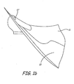
- FIGS. 1a and 1b are side and top views respectively of the composite blade of this invention with a sheath.
- FIG. 2 is a side view of an open mould for forming the composite blade of FIG. 2 while simultaneously bonding a sheath to the leading edge of the blade, prior to closing the mould.
- FIG. 3 is a block diagram illustrating a method of forming the composite blade and sheath of this invention.
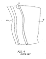
- FIG. 4 is a side view of a prior art process for placing a sheath on a blade.
- FIGS. 1 a and 1 b illustrate composite blade 10 having trailing edge 12, leading edge 14, sheath 17, tip 20, and root 24.
- Root 24 is illustrated as a dovetail root. However, root 24 can have any configuration that is used in blade assemblies.
- Sheath 17 is bonded to its leading edge 14 using the process of this invention, in which the dry composite blade 10 and the sheath 17 are placed in a mould and cured at the same time, as described hereinafter.
- Blade 10 is a composite preform made from a woven three dimensional centre core with laid on filament plies as describe below. Alternatively the composite may be simply a woven three dimensional core or a plurality of filament plies.
- blades such as helicopter or propellers that have a foamed centre or honeycomb centre to lighten the weight of the blade.
- Any kind of composite blade that can be resin moulded from a dry preform is part of this invention.
- the method of this invention may be used with any blade having a dry composite outer surface.
- Sheath 17 may be made from any of the conventional materials.
- sheath 17 can be made from any hard material, such as titanium and nickel sheaths, and those made from alloys of these metals.
- Sheath 17 may be made from other metals and other materials such as ceramics, plastics such as polyurethane or epoxy filled fibre materials, and the like.
- Sheath 17 may have a primer or adhesive used therewith, where the primer or adhesive is applied to sheath 17 or dry preform 10 to enhance adhesion of sheath 17 to preform 10 as it is being cured to ensure that sheath 17 will remain in place during use of the final product.
- FIG. 1b also illustrate how a tip cover 21 and trailing edge sheath 21 can be added to the blade 11 by providing space in the mould for those components.
- FIG 1a illustrates how leading edge sheath 17 is a separate component, showing break 23 is between sheath 17 and trailing edge sheath 21. It has been found that the process of this invention provides increased conformity to the junction of leading edge sheath 17, tip sheath 19 and trailing edge sheath 21 to blade 10.
- a method of fabricating a composite blade 10 is disclosed in a U.S. Patent Application titled Core Driven Ply Shape Composite Fan Blade and Method of Making, filed November 30, 2009, having Serial No. 12/627,629 , which is incorporated herein by reference in its entirety.
- composite blades that are formed solely from a 3-D woven core or solely from plies are also capable of use in the present invention. Also used are those composite blades that have hollow or filled centres, such as with foam or a honeycombed structure to lighten the overall weight of the blade. All that is required of the moulded composite blade is that it be dry when inserted in the mould, cured in a mould with a resin while in contact with a sheath in the mould to thereby form a complete sheath covered blade.
- FIG. 2 illustrates one example of composite blade 10 in mould 32 having an upper mould 33 and lower mould 34.
- Mould 32 is designed based on the desired outside geometry of blade 10.
- Plies 38 and woven core 36 are stacked in mould 32 and eventually cured with a resin to form composite blade 10.
- Plies 38 are stacked on outer surfaces of woven core 36.
- Sheath 17 is then placed on top of plies 38 in mould 32.
- Plies 38, sheath 17 and woven core 36 occupy the entire hollow space in mould 32.
- the dry composite preform can be any known form of composite, including those of both a core and plies as above or solely a core or solely plies.
- the mould is closed and the resin is then transferred into closed mould 32, heat is applied and the resin cures to form the finished product. It is important to have the dry blade 10 and the sheath 17 in the mould and in contact when the resin is added and cured.
- the flow chart of FIG. 3 illustrates method 40 of forming composite blade 10, which includes the steps of forming the woven core and sheath (step 42), placing sheath 17 in the against the desired edge of the composite blade 10 (step 44), placing the woven core 36 in the mould with the sheath 17 on the desired edge (step 46), inserting a resin and curing the composite and sheath in place (step 48), and removing the composite with sheath 17 attached (step 50).
- the composite blade 10 is thus formed using a resin transfer moulding process.
- the resin is inserted into mould 32 such as in direction arrow A.
- the resin is cured to produce blade 10 having sheath 17.
- Plies 38 may be sprayed with an epoxy adhesive, particularly if sheath 17 is made from titanium or a titanium alloy.
- a film adhesive layer may be applied to the bonding surfaces of sheath 17 before placement in the mould to ensure enhanced bonding properties of a true adhesive are used.
- the portion of the dry composite may have a film adhesive applied prior to joining the sheath and blade. Any conventional adhesive used to bond metal such as titanium and nickel to materials such as composites may be used in this step.
- the resin can be an epoxy polymer resin system or any other resin system conventionally used in resin transfer moulding products such as airfoil blades that operate at high temperatures and other stress inducing conditions.
- FIG. 4 illustrates a prior art method for placing a protective sheath on a composite blade such as those used in gas turbine engines.
- a formed blade 54 has an adhesive film placed on the leading edge 53 of blade 54.
- a leading edge sheath 55 is placed against the adhesive film and the adhesive is cured, thereby bonding the sheath to the blade.
- This process requires that leading edge 53 of blade 54 and sheath 55 mate together with close tolerances. If the surfaces do not match, impact from birds, hail or other objects ingested by the engine will loosen the sheath prior to its intended operating life. The cost of providing close tolerances and the additional tooling and heating are considerable.
- a blade with a sheath is formed in a single moulding step, thus eliminating the cost of additional tooling and an adhesive bonding and curing step.
- the junction between the sheath and the blade is improved because they are mated prior to curing the resin that forms the blade, thus ensuring that there is essentially 100% contact between the leading edge of the blade and the sheath itself.
- the process of this invention can be used with any method of forming a composite blade by injecting and curing a resin, with or without an adhesive as desired. Wear life of sheathed blades according to the process of this invention is improved, due to the complete matching of the surface between the blade and sheath.
Landscapes
- Engineering & Computer Science (AREA)
- Mechanical Engineering (AREA)
- Chemical & Material Sciences (AREA)
- Composite Materials (AREA)
- General Engineering & Computer Science (AREA)
- Materials Engineering (AREA)
- Architecture (AREA)
- Structures Of Non-Positive Displacement Pumps (AREA)
- Turbine Rotor Nozzle Sealing (AREA)
Applications Claiming Priority (1)
| Application Number | Priority Date | Filing Date | Title |
|---|---|---|---|
| US12/701,244 US20110194941A1 (en) | 2010-02-05 | 2010-02-05 | Co-cured sheath for composite blade |
Publications (2)
| Publication Number | Publication Date |
|---|---|
| EP2353830A2 true EP2353830A2 (fr) | 2011-08-10 |
| EP2353830A3 EP2353830A3 (fr) | 2015-06-17 |
Family
ID=43920085
Family Applications (1)
| Application Number | Title | Priority Date | Filing Date |
|---|---|---|---|
| EP11250124.2A Withdrawn EP2353830A3 (fr) | 2010-02-05 | 2011-02-03 | Procédé de fabrication d'une aube de soufflante en composite avec gaine durcie dans la masse et aube de soufflante associée |
Country Status (2)
| Country | Link |
|---|---|
| US (1) | US20110194941A1 (fr) |
| EP (1) | EP2353830A3 (fr) |
Cited By (20)
| Publication number | Priority date | Publication date | Assignee | Title |
|---|---|---|---|---|
| EP2604794A1 (fr) * | 2011-12-14 | 2013-06-19 | United Technologies Corporation | Mise à la masse électrique pour pales de ventilateur |
| FR2991710A1 (fr) * | 2012-06-06 | 2013-12-13 | Snecma | Aube de turbomachine comportant un insert recouvrant le bord de fuite |
| FR2992887A1 (fr) * | 2012-07-09 | 2014-01-10 | Snecma | Procede de fixation d'un renfort metallique structurel sur une partie d'une aube de turbine a gaz en materiau composite et moule d'injection pour la mise en oeuvre d'un tel procede |
| FR2995037A1 (fr) * | 2012-08-31 | 2014-03-07 | Snecma | Collage d'un element intermediaire de fixation rapporte sur une piece de turbomachine |
| WO2014133613A2 (fr) | 2012-12-20 | 2014-09-04 | United Technologies Corporation | Pales de ventilateur pour turbines à gaz à concentration de contraintes réduite au niveau du bord d'attaque |
| US8876482B2 (en) | 2012-09-11 | 2014-11-04 | United Technologies Corporation | Electrical grounding for blade sheath |
| FR3008920A1 (fr) * | 2013-07-29 | 2015-01-30 | Safran | Procede de fabrication d'une aube en materiau composite a bord d'attaque metallique integre pour moteur aeronautique a turbine a gaz |
| WO2015099937A1 (fr) * | 2013-12-23 | 2015-07-02 | United Technologies Corporation | Pale de ventilateur avec empilage de tissu adhésif |
| US9212559B2 (en) | 2012-09-07 | 2015-12-15 | United Technologies Corporation | Electrical grounding for blades |
| WO2016030613A1 (fr) * | 2014-08-27 | 2016-03-03 | Snecma | Aube de redresseur en matériau composite pour moteur a turbine a gaz et son procédé de fabrication. |
| US9297272B2 (en) | 2012-10-24 | 2016-03-29 | United Technologies Corporation | Grounding for fan blades on an underblade spacer |
| EP3023602A1 (fr) * | 2014-11-21 | 2016-05-25 | General Electric Company | Ensemble moteur de turbine et procédé de fabrication associé |
| US9394805B2 (en) | 2012-09-27 | 2016-07-19 | United Technologies Corporation | Diode electrical ground for fan blades |
| FR3049001A1 (fr) * | 2016-03-21 | 2017-09-22 | Snecma | Turbomachine aeronautique a helice non carenee munie de pales ayant un element rapporte en materiau composite colle sur leur bord d'attaque |
| FR3049002A1 (fr) * | 2016-03-21 | 2017-09-22 | Snecma | Pale de turbomachine aeronautique comprenant un element rapporte en materiau composite formant bord de fuite et procede de fabrication d'une telle pale |
| EP3486432A1 (fr) | 2017-11-21 | 2019-05-22 | Ansaldo Energia Switzerland AG | Lame et son procédé de fabrication |
| CN110682544A (zh) * | 2019-10-08 | 2020-01-14 | 江西洪都航空工业集团有限责任公司 | 一种薄壁复合材料前缘整流罩的胶接模具及胶接方法 |
| US10677090B2 (en) | 2017-05-10 | 2020-06-09 | General Electric Company | Component having co-bonded composite and metal rings and method of assembling same |
| CN112607003A (zh) * | 2020-11-25 | 2021-04-06 | 常州市长昊机械有限公司 | 一种易收纳式航空叶片 |
| FR3140007A1 (fr) * | 2022-09-26 | 2024-03-29 | Safran Aircraft Engines | Outillage et procede de fabrication d’une aube composite pour un moteur d’aeronef |
Families Citing this family (63)
| Publication number | Priority date | Publication date | Assignee | Title |
|---|---|---|---|---|
| IT1394295B1 (it) | 2009-05-08 | 2012-06-06 | Nuovo Pignone Spa | Girante centrifuga del tipo chiuso per turbomacchine, componente per tale girante, turbomacchina provvista di tale girante e metodo di realizzazione di tale girante |
| US8075274B2 (en) * | 2009-05-13 | 2011-12-13 | Hamilton Sundstrand Corporation | Reinforced composite fan blade |
| US8814527B2 (en) * | 2009-08-07 | 2014-08-26 | Hamilton Sundstrand Corporation | Titanium sheath and airfoil assembly |
| US20110116906A1 (en) * | 2009-11-17 | 2011-05-19 | Smith Blair A | Airfoil component wear indicator |
| IT1397058B1 (it) | 2009-11-23 | 2012-12-28 | Nuovo Pignone Spa | Stampo per girante centrifuga, inserti per stampo e metodo per costruire una girante centrifuga |
| IT1397057B1 (it) | 2009-11-23 | 2012-12-28 | Nuovo Pignone Spa | Girante centrifuga e turbomacchina |
| US20110229334A1 (en) * | 2010-03-16 | 2011-09-22 | United Technologies Corporation | Composite leading edge sheath and dovetail root undercut |
| CH705171A1 (de) * | 2011-06-21 | 2012-12-31 | Alstom Technology Ltd | Turbinenschaufel mit einem Schaufelblatt aus Verbundwerkstoff und Verfahren zum Herstellen davon. |
| US8834126B2 (en) * | 2011-06-30 | 2014-09-16 | United Technologies Corporation | Fan blade protection system |
| ITCO20110064A1 (it) | 2011-12-14 | 2013-06-15 | Nuovo Pignone Spa | Macchina rotante comprendente un rotore con una girante composita ed un albero metallico |
| US9752441B2 (en) | 2012-01-31 | 2017-09-05 | United Technologies Corporation | Gas turbine rotary blade with tip insert |
| US9140130B2 (en) | 2012-03-08 | 2015-09-22 | United Technologies Corporation | Leading edge protection and method of making |
| BR112015001828A2 (pt) | 2012-07-30 | 2017-07-04 | Gen Electric | tira protetora, aerofólio de uma turbomáquina, método de fabricação de um aerofólio e aerofólio com a tira protetora |
| US8986484B2 (en) * | 2012-10-10 | 2015-03-24 | The Boeing Company | Shape-distorting tooling system and method for curing composite parts |
| US10385703B2 (en) | 2013-03-08 | 2019-08-20 | United Technologies Corporation | Fan blades with protective sheaths and galvanic shields |
| US20160010470A1 (en) * | 2013-03-14 | 2016-01-14 | United Technologies Corporation | Frangible Sheath for a Fan Blade of a Gas Turbine Engine |
| EP2971526B1 (fr) * | 2013-03-15 | 2018-10-24 | United Technologies Corporation | Gaine de bord d'attaque allongée localement pour pale à profil aérodynamique de ventilateur |
| FR3005280B1 (fr) * | 2013-05-06 | 2015-05-15 | Safran | Outillage pour la fixation d'un renfort metallique sur le bord d'attaque d'une aube de turbomachine et procede utilisant un tel outillage |
| US10519788B2 (en) | 2013-05-29 | 2019-12-31 | General Electric Company | Composite airfoil metal patch |
| WO2014204573A1 (fr) * | 2013-06-17 | 2014-12-24 | United Technologies Corporation | Profil aérodynamique composite relié à une emplanture métallique |
| US10358929B2 (en) * | 2013-07-15 | 2019-07-23 | United Technologies Corporation | Composite airfoil |
| US10125620B2 (en) * | 2013-07-29 | 2018-11-13 | United Technologies Corporation | Gas turbine engine CMC airfoil assembly |
| GB201313779D0 (en) * | 2013-08-01 | 2013-09-18 | Blade Dynamics Ltd | Erosion resistant aerodynamic fairing |
| WO2015069335A2 (fr) * | 2013-09-09 | 2015-05-14 | United Technologies Corporation | Pales de ventilateur et procédés de fabrication |
| EP3044419B1 (fr) * | 2013-09-09 | 2019-10-02 | United Technologies Corporation | Aube et procédé de fabrication |
| US20160298644A1 (en) * | 2013-09-27 | 2016-10-13 | United Technologies Corporation | Fan blade assembly |
| WO2015047752A1 (fr) * | 2013-09-27 | 2015-04-02 | United Technologies Corporation | Ensemble pale de soufflante |
| FR3012515B1 (fr) * | 2013-10-31 | 2018-02-09 | Safran | Aube composite de turbomachine |
| ITCO20130067A1 (it) | 2013-12-17 | 2015-06-18 | Nuovo Pignone Srl | Girante con elementi di protezione e compressore centrifugo |
| CA2936196A1 (fr) | 2014-01-16 | 2015-07-23 | General Electric Company | Cale de reduction de contrainte de pied de pale composite |
| FR3017884B1 (fr) | 2014-02-25 | 2017-09-22 | Snecma | Bord de protection d'aube et son procede de fabrication |
| US20150345310A1 (en) * | 2014-05-29 | 2015-12-03 | General Electric Company | Turbine bucket assembly and turbine system |
| DE102014226700A1 (de) * | 2014-12-19 | 2016-06-23 | Rolls-Royce Deutschland Ltd & Co Kg | Kompressorschaufel einer Gasturbine |
| FR3035679B1 (fr) * | 2015-04-29 | 2018-06-01 | Safran Aircraft Engines | Aube composite, comprenant un renfort de bord d'attaque en un autre materiau |
| FR3041684B1 (fr) * | 2015-09-28 | 2021-12-10 | Snecma | Aube comprenant un bouclier de bord d'attaque et procede de fabrication de l'aube |
| US10677259B2 (en) | 2016-05-06 | 2020-06-09 | General Electric Company | Apparatus and system for composite fan blade with fused metal lead edge |
| US10815797B2 (en) | 2016-08-12 | 2020-10-27 | Hamilton Sundstrand Corporation | Airfoil systems and methods of assembly |
| JP6968006B2 (ja) * | 2018-03-09 | 2021-11-17 | 三菱重工業株式会社 | 前縁カバー部材、前縁カバー部材ユニット、複合材翼、前縁カバー部材の製造方法及び複合材翼の製造方法 |
| US11073027B2 (en) | 2018-05-17 | 2021-07-27 | Raytheon Technologies Corporation | Mold tool and methods for airfoil bonding |
| US11111815B2 (en) | 2018-10-16 | 2021-09-07 | General Electric Company | Frangible gas turbine engine airfoil with fusion cavities |
| US11434781B2 (en) | 2018-10-16 | 2022-09-06 | General Electric Company | Frangible gas turbine engine airfoil including an internal cavity |
| US10760428B2 (en) | 2018-10-16 | 2020-09-01 | General Electric Company | Frangible gas turbine engine airfoil |
| US10746045B2 (en) | 2018-10-16 | 2020-08-18 | General Electric Company | Frangible gas turbine engine airfoil including a retaining member |
| US11149558B2 (en) | 2018-10-16 | 2021-10-19 | General Electric Company | Frangible gas turbine engine airfoil with layup change |
| US10837286B2 (en) | 2018-10-16 | 2020-11-17 | General Electric Company | Frangible gas turbine engine airfoil with chord reduction |
| US10822969B2 (en) | 2018-10-18 | 2020-11-03 | Raytheon Technologies Corporation | Hybrid airfoil for gas turbine engines |
| US20200157953A1 (en) * | 2018-11-20 | 2020-05-21 | General Electric Company | Composite fan blade with abrasive tip |
| US10774653B2 (en) | 2018-12-11 | 2020-09-15 | Raytheon Technologies Corporation | Composite gas turbine engine component with lattice structure |
| FR3098188B1 (fr) * | 2019-07-02 | 2021-10-29 | Airbus Operations Sas | Procédé de fabrication d’un générateur de tourbillons pour une paroi aérodynamique d’un aéronef comprenant au moins un bord d’attaque protégé |
| US11215054B2 (en) | 2019-10-30 | 2022-01-04 | Raytheon Technologies Corporation | Airfoil with encapsulating sheath |
| US11466576B2 (en) * | 2019-11-04 | 2022-10-11 | Raytheon Technologies Corporation | Airfoil with continuous stiffness joint |
| FR3103731B1 (fr) | 2019-11-29 | 2021-11-26 | Safran | Aube composite pour un moteur d’aeronef et ses procedes de fabrication et de reparation |
| FR3103730B1 (fr) * | 2019-11-29 | 2021-12-03 | Safran | Procede de fabrication d’une aube composite pour un moteur d’aeronef |
| US11073030B1 (en) | 2020-05-21 | 2021-07-27 | Raytheon Technologies Corporation | Airfoil attachment for gas turbine engines |
| US11352891B2 (en) | 2020-10-19 | 2022-06-07 | Pratt & Whitney Canada Corp. | Method for manufacturing a composite guide vane having a metallic leading edge |
| US12116903B2 (en) | 2021-06-30 | 2024-10-15 | General Electric Company | Composite airfoils with frangible tips |
| US11674399B2 (en) | 2021-07-07 | 2023-06-13 | General Electric Company | Airfoil arrangement for a gas turbine engine utilizing a shape memory alloy |
| US11668317B2 (en) | 2021-07-09 | 2023-06-06 | General Electric Company | Airfoil arrangement for a gas turbine engine utilizing a shape memory alloy |
| US12017787B2 (en) * | 2021-09-07 | 2024-06-25 | Experimental Vehicle Engineering Ltd. | Aircraft propeller blade radiator |
| US11988103B2 (en) * | 2021-10-27 | 2024-05-21 | General Electric Company | Airfoils for a fan section of a turbine engine |
| US20230392504A1 (en) * | 2022-06-03 | 2023-12-07 | Raytheon Technologies Corporation | Polymeric foams for hollow cavities |
| FR3141093B1 (fr) * | 2022-10-20 | 2024-09-13 | Safran Aircraft Engines | Moule de conformage et d’injection pour la fabrication d’une piece et procede de fabrication d’une telle piece au moyen du moule |
| FR3141721A1 (fr) * | 2022-11-09 | 2024-05-10 | Safran | Support d’encollage de renfort et procédé d’encollage de renfort à l’aide d’un tel support d’encollage |
Citations (2)
| Publication number | Priority date | Publication date | Assignee | Title |
|---|---|---|---|---|
| US5881972A (en) | 1997-03-05 | 1999-03-16 | United Technologies Corporation | Electroformed sheath and airfoiled component construction |
| US5908285A (en) | 1995-03-10 | 1999-06-01 | United Technologies Corporation | Electroformed sheath |
Family Cites Families (16)
| Publication number | Priority date | Publication date | Assignee | Title |
|---|---|---|---|---|
| US4022547A (en) * | 1975-10-02 | 1977-05-10 | General Electric Company | Composite blade employing biased layup |
| US5279892A (en) * | 1992-06-26 | 1994-01-18 | General Electric Company | Composite airfoil with woven insert |
| US5509781A (en) * | 1994-02-09 | 1996-04-23 | United Technologies Corporation | Compressor blade containment with composite stator vanes |
| FR2732406B1 (fr) * | 1995-03-29 | 1997-08-29 | Snecma | Aube de turbomachine en materiau composite |
| US5655883A (en) * | 1995-09-25 | 1997-08-12 | General Electric Company | Hybrid blade for a gas turbine |
| JPH1054204A (ja) * | 1996-05-20 | 1998-02-24 | General Electric Co <Ge> | ガスタービン用の多構成部翼 |
| US6431837B1 (en) * | 1999-06-01 | 2002-08-13 | Alexander Velicki | Stitched composite fan blade |
| US6413051B1 (en) * | 2000-10-30 | 2002-07-02 | General Electric Company | Article including a composite laminated end portion with a discrete end barrier and method for making and repairing |
| AUPR373901A0 (en) * | 2001-03-14 | 2001-04-12 | Leach Aero Services Pty Ltd | An article having an erodynamic surface |
| US6843928B2 (en) * | 2001-10-12 | 2005-01-18 | General Electric Company | Method for removing metal cladding from airfoil substrate |
| US6607358B2 (en) * | 2002-01-08 | 2003-08-19 | General Electric Company | Multi-component hybrid turbine blade |
| FR2861143B1 (fr) * | 2003-10-20 | 2006-01-20 | Snecma Moteurs | Aube de turbomachine, notamment aube de soufflante et son procede de fabrication |
| FR2892339B1 (fr) * | 2005-10-21 | 2009-08-21 | Snecma Sa | Procede de fabrication d'une aube de turbomachine composite, et aube obtenue par ce procede |
| FR2906320B1 (fr) * | 2006-09-26 | 2008-12-26 | Snecma Sa | Aube composite de turbomachine a renfort metallique |
| US7780410B2 (en) * | 2006-12-27 | 2010-08-24 | General Electric Company | Method and apparatus for gas turbine engines |
| ATE500050T1 (de) * | 2008-05-21 | 2011-03-15 | Siemens Ag | Verfahren zur herstellung eines verbundstoffes |
-
2010
- 2010-02-05 US US12/701,244 patent/US20110194941A1/en not_active Abandoned
-
2011
- 2011-02-03 EP EP11250124.2A patent/EP2353830A3/fr not_active Withdrawn
Patent Citations (2)
| Publication number | Priority date | Publication date | Assignee | Title |
|---|---|---|---|---|
| US5908285A (en) | 1995-03-10 | 1999-06-01 | United Technologies Corporation | Electroformed sheath |
| US5881972A (en) | 1997-03-05 | 1999-03-16 | United Technologies Corporation | Electroformed sheath and airfoiled component construction |
Cited By (39)
| Publication number | Priority date | Publication date | Assignee | Title |
|---|---|---|---|---|
| US9376924B2 (en) | 2011-12-14 | 2016-06-28 | United Technologies Corporation | Electrical grounding for fan blades |
| EP2604794A1 (fr) * | 2011-12-14 | 2013-06-19 | United Technologies Corporation | Mise à la masse électrique pour pales de ventilateur |
| FR2991710A1 (fr) * | 2012-06-06 | 2013-12-13 | Snecma | Aube de turbomachine comportant un insert recouvrant le bord de fuite |
| US10259169B2 (en) | 2012-07-09 | 2019-04-16 | Safran Aircraft Engines | Method of fastening structural metal reinforcement on a portion of a gas turbine blade made of composite material, and an injection mold for performing such a method |
| CN104428128B (zh) * | 2012-07-09 | 2017-01-18 | 斯奈克玛 | 将金属结构性加强件固定到包括复合材料的气体涡轮叶片的一部分上的方法,以及实施该方法的注入模 |
| FR2992887A1 (fr) * | 2012-07-09 | 2014-01-10 | Snecma | Procede de fixation d'un renfort metallique structurel sur une partie d'une aube de turbine a gaz en materiau composite et moule d'injection pour la mise en oeuvre d'un tel procede |
| RU2638401C2 (ru) * | 2012-07-09 | 2017-12-13 | Снекма | Способ закрепления конструктивного металлического усиливающего элемента на изготовленной из композитного материала части лопатки газовой турбины и форма для литья под давлением, обеспечивающая осуществление такого способа |
| CN104428128A (zh) * | 2012-07-09 | 2015-03-18 | 斯奈克玛 | 将金属结构性加强件固定到包括复合材料的气体涡轮叶片的一部分上的方法,以及实施该方法的注入模 |
| WO2014009635A1 (fr) * | 2012-07-09 | 2014-01-16 | Snecma | Procede de fixation d'un renfort metallique structurel sur une partie d'une aube de turbine a gaz en materiau composite et moule d'injection pour la mise en œuvre d'un tel procede. |
| FR2995037A1 (fr) * | 2012-08-31 | 2014-03-07 | Snecma | Collage d'un element intermediaire de fixation rapporte sur une piece de turbomachine |
| US9212559B2 (en) | 2012-09-07 | 2015-12-15 | United Technologies Corporation | Electrical grounding for blades |
| US8876482B2 (en) | 2012-09-11 | 2014-11-04 | United Technologies Corporation | Electrical grounding for blade sheath |
| US9394805B2 (en) | 2012-09-27 | 2016-07-19 | United Technologies Corporation | Diode electrical ground for fan blades |
| US9297272B2 (en) | 2012-10-24 | 2016-03-29 | United Technologies Corporation | Grounding for fan blades on an underblade spacer |
| EP2935796A4 (fr) * | 2012-12-20 | 2015-12-23 | United Technologies Corp | Pales de ventilateur pour turbines à gaz à concentration de contraintes réduite au niveau du bord d'attaque |
| WO2014133613A2 (fr) | 2012-12-20 | 2014-09-04 | United Technologies Corporation | Pales de ventilateur pour turbines à gaz à concentration de contraintes réduite au niveau du bord d'attaque |
| US9617860B2 (en) | 2012-12-20 | 2017-04-11 | United Technologies Corporation | Fan blades for gas turbine engines with reduced stress concentration at leading edge |
| WO2015015091A1 (fr) * | 2013-07-29 | 2015-02-05 | Safran | Procédé de fabrication d'une aube en matériau composite à bord d'attaque métallique intégré pour moteur aéronautique à turbine à gaz |
| FR3008920A1 (fr) * | 2013-07-29 | 2015-01-30 | Safran | Procede de fabrication d'une aube en materiau composite a bord d'attaque metallique integre pour moteur aeronautique a turbine a gaz |
| US10899051B2 (en) | 2013-07-29 | 2021-01-26 | Safran | Method of fabricating a composite material blade having an integrated metal leading edge for a gas turbine aeroengine |
| WO2015099937A1 (fr) * | 2013-12-23 | 2015-07-02 | United Technologies Corporation | Pale de ventilateur avec empilage de tissu adhésif |
| US10982683B2 (en) | 2013-12-23 | 2021-04-20 | Raytheon Technologies Corporation | Fan blade with adhesive fabric stackup |
| WO2016030613A1 (fr) * | 2014-08-27 | 2016-03-03 | Snecma | Aube de redresseur en matériau composite pour moteur a turbine a gaz et son procédé de fabrication. |
| FR3025248A1 (fr) * | 2014-08-27 | 2016-03-04 | Snecma | Aube de redresseur en materiau composite pour moteur a turbine a gaz et son procede de fabrication |
| US20170254212A1 (en) * | 2014-08-27 | 2017-09-07 | Safran Aircraft Engines | A guide vane made of composite material for a gas turbine engine, and it's method of fabrication |
| CN106794641A (zh) * | 2014-08-27 | 2017-05-31 | 赛峰飞机发动机公司 | 用于气体涡轮发动机的、由复合材料制成的导向叶片及其制造方法 |
| RU2703225C2 (ru) * | 2014-08-27 | 2019-10-15 | Сафран Эркрафт Энджинз | Направляющая лопатка для газотурбинного двигателя, сделанная из композиционного материала, и способ ее изготовления |
| EP3023602A1 (fr) * | 2014-11-21 | 2016-05-25 | General Electric Company | Ensemble moteur de turbine et procédé de fabrication associé |
| FR3049001A1 (fr) * | 2016-03-21 | 2017-09-22 | Snecma | Turbomachine aeronautique a helice non carenee munie de pales ayant un element rapporte en materiau composite colle sur leur bord d'attaque |
| WO2017162964A1 (fr) * | 2016-03-21 | 2017-09-28 | Safran Aircraft Engines | Turbomachine aéronautique à hélice non carénée munie de pales ayant un élément rapporte en matériau composite colle sur leur bord d'attaque |
| FR3049002A1 (fr) * | 2016-03-21 | 2017-09-22 | Snecma | Pale de turbomachine aeronautique comprenant un element rapporte en materiau composite formant bord de fuite et procede de fabrication d'une telle pale |
| US11401823B2 (en) | 2016-03-21 | 2022-08-02 | Safran Aircraft Engines | Aircraft turbomachine provided with an unducted propeller with blades having a composite-material insert bonded to their leading edges |
| US10677090B2 (en) | 2017-05-10 | 2020-06-09 | General Electric Company | Component having co-bonded composite and metal rings and method of assembling same |
| EP3486432A1 (fr) | 2017-11-21 | 2019-05-22 | Ansaldo Energia Switzerland AG | Lame et son procédé de fabrication |
| CN110682544A (zh) * | 2019-10-08 | 2020-01-14 | 江西洪都航空工业集团有限责任公司 | 一种薄壁复合材料前缘整流罩的胶接模具及胶接方法 |
| CN112607003A (zh) * | 2020-11-25 | 2021-04-06 | 常州市长昊机械有限公司 | 一种易收纳式航空叶片 |
| CN112607003B (zh) * | 2020-11-25 | 2023-06-20 | 常州市长昊机械有限公司 | 一种易收纳式航空叶片 |
| WO2024069077A1 (fr) | 2022-09-26 | 2024-04-04 | Safran Aircraft Engines | Outillage et procede de fabrication d'une aube composite pour un moteur d'aeronef |
| FR3140007A1 (fr) * | 2022-09-26 | 2024-03-29 | Safran Aircraft Engines | Outillage et procede de fabrication d’une aube composite pour un moteur d’aeronef |
Also Published As
| Publication number | Publication date |
|---|---|
| US20110194941A1 (en) | 2011-08-11 |
| EP2353830A3 (fr) | 2015-06-17 |
Similar Documents
| Publication | Publication Date | Title |
|---|---|---|
| EP2353830A2 (fr) | Procédé de fabrication d'une aube de soufflante en composite avec gaine durcie dans la masse et aube de soufflante associée | |
| EP1462606B1 (fr) | Aube hybride pour turbines à gaz composée de plusieurs composants | |
| EP2378079A2 (fr) | Gaine composite de bord d'attaque et entaille d'ancrage de queue d'aronde | |
| EP3037675B1 (fr) | Ailette composite | |
| EP3044415B1 (fr) | Profil aérodynamique ayant un revêtement composite intégralement rigidifié | |
| US20190360345A1 (en) | Blade body and a blade made of composite material having fiber reinforcement made up both of three-dimensional weaving and also of short fibers, and method of fabrication | |
| EP2971549B1 (fr) | Aube rotorique de moteur à turbine à gaz, moteur à turbine à gaz et procédé de manufacture associés | |
| US9217333B2 (en) | Composite-material vane | |
| CN105934327A (zh) | 耐腐蚀空气动力整流件 | |
| US9878501B2 (en) | Method of manufacturing a frangible blade | |
| EP2253803B1 (fr) | Aube composite avec extrémité résistant à l'usure et procédé correspondant | |
| CN110778365B (zh) | 带金属加强件的复合叶片及其制造方法 | |
| US20120018079A1 (en) | Rotor blade of a gas turbine engine made of composite material comprising a connecting yoke, method for manufacturing the blade | |
| CN107075958A (zh) | 由机械锚固元件组装的两个零件的组件,由复合材料制成的一个零件 | |
| US20230003133A1 (en) | Blade made of composite material with variable-density attached leading edge | |
| US9243512B1 (en) | Rotary machine with a frangible composite blade | |
| CN108026778A (zh) | 包括前缘防护件的叶片及生产该叶片的方法 | |
| US9828862B2 (en) | Frangible airfoil | |
| US8221087B2 (en) | Stator vanes of a stator vane cascade of an aircraft gas turbine | |
| CN107407154B (zh) | 易碎复合翼型件 | |
| EP3406434A1 (fr) | Lame composite et procédé de fabrication | |
| GB2521047A (en) | A composite vane for a turbine engine | |
| CN112867845A (zh) | 防护部件 | |
| US20240141917A1 (en) | Blade comprising a structure made of composite material and associated manufacturing method | |
| US11401823B2 (en) | Aircraft turbomachine provided with an unducted propeller with blades having a composite-material insert bonded to their leading edges |
Legal Events
| Date | Code | Title | Description |
|---|---|---|---|
| PUAI | Public reference made under article 153(3) epc to a published international application that has entered the european phase |
Free format text: ORIGINAL CODE: 0009012 |
|
| AK | Designated contracting states |
Kind code of ref document: A2 Designated state(s): AL AT BE BG CH CY CZ DE DK EE ES FI FR GB GR HR HU IE IS IT LI LT LU LV MC MK MT NL NO PL PT RO RS SE SI SK SM TR |
|
| AX | Request for extension of the european patent |
Extension state: BA ME |
|
| PUAL | Search report despatched |
Free format text: ORIGINAL CODE: 0009013 |
|
| AK | Designated contracting states |
Kind code of ref document: A3 Designated state(s): AL AT BE BG CH CY CZ DE DK EE ES FI FR GB GR HR HU IE IS IT LI LT LU LV MC MK MT NL NO PL PT RO RS SE SI SK SM TR |
|
| AX | Request for extension of the european patent |
Extension state: BA ME |
|
| RIC1 | Information provided on ipc code assigned before grant |
Ipc: F01D 5/28 20060101ALI20150511BHEP Ipc: B29C 43/18 20060101AFI20150511BHEP Ipc: F04D 29/02 20060101ALI20150511BHEP |
|
| STAA | Information on the status of an ep patent application or granted ep patent |
Free format text: STATUS: THE APPLICATION IS DEEMED TO BE WITHDRAWN |
|
| 18D | Application deemed to be withdrawn |
Effective date: 20151218 |