EP2353777A1 - Self-centring support - Google Patents
Self-centring support Download PDFInfo
- Publication number
- EP2353777A1 EP2353777A1 EP10152923A EP10152923A EP2353777A1 EP 2353777 A1 EP2353777 A1 EP 2353777A1 EP 10152923 A EP10152923 A EP 10152923A EP 10152923 A EP10152923 A EP 10152923A EP 2353777 A1 EP2353777 A1 EP 2353777A1
- Authority
- EP
- European Patent Office
- Prior art keywords
- shaft
- electric motor
- workpiece
- hollow shaft
- holding members
- Prior art date
- Legal status (The legal status is an assumption and is not a legal conclusion. Google has not performed a legal analysis and makes no representation as to the accuracy of the status listed.)
- Granted
Links
Images


Classifications
-
- B—PERFORMING OPERATIONS; TRANSPORTING
- B23—MACHINE TOOLS; METAL-WORKING NOT OTHERWISE PROVIDED FOR
- B23B—TURNING; BORING
- B23B13/00—Arrangements for automatically conveying or chucking or guiding stock
- B23B13/08—Arrangements for reducing vibrations in feeding-passages or for damping noise
-
- B—PERFORMING OPERATIONS; TRANSPORTING
- B23—MACHINE TOOLS; METAL-WORKING NOT OTHERWISE PROVIDED FOR
- B23Q—DETAILS, COMPONENTS, OR ACCESSORIES FOR MACHINE TOOLS, e.g. ARRANGEMENTS FOR COPYING OR CONTROLLING; MACHINE TOOLS IN GENERAL CHARACTERISED BY THE CONSTRUCTION OF PARTICULAR DETAILS OR COMPONENTS; COMBINATIONS OR ASSOCIATIONS OF METAL-WORKING MACHINES, NOT DIRECTED TO A PARTICULAR RESULT
- B23Q1/00—Members which are comprised in the general build-up of a form of machine, particularly relatively large fixed members
- B23Q1/72—Auxiliary arrangements; Interconnections between auxiliary tables and movable machine elements
- B23Q1/76—Steadies; Rests
-
- B—PERFORMING OPERATIONS; TRANSPORTING
- B23—MACHINE TOOLS; METAL-WORKING NOT OTHERWISE PROVIDED FOR
- B23B—TURNING; BORING
- B23B13/00—Arrangements for automatically conveying or chucking or guiding stock
- B23B13/12—Accessories, e.g. stops, grippers
-
- B—PERFORMING OPERATIONS; TRANSPORTING
- B23—MACHINE TOOLS; METAL-WORKING NOT OTHERWISE PROVIDED FOR
- B23B—TURNING; BORING
- B23B25/00—Accessories or auxiliary equipment for turning-machines
-
- Y—GENERAL TAGGING OF NEW TECHNOLOGICAL DEVELOPMENTS; GENERAL TAGGING OF CROSS-SECTIONAL TECHNOLOGIES SPANNING OVER SEVERAL SECTIONS OF THE IPC; TECHNICAL SUBJECTS COVERED BY FORMER USPC CROSS-REFERENCE ART COLLECTIONS [XRACs] AND DIGESTS
- Y10—TECHNICAL SUBJECTS COVERED BY FORMER USPC
- Y10T—TECHNICAL SUBJECTS COVERED BY FORMER US CLASSIFICATION
- Y10T82/00—Turning
- Y10T82/25—Lathe
- Y10T82/2593—Work rest
- Y10T82/2597—Center rest
Definitions
- Such lunettes are manufactured by the patent applicant for decades and successfully placed in the market.
- the EP 0 562 180 B1 such a bezel can be removed.
- a threaded bore 13 is further incorporated, into which a threaded spindle 14 is screwed.
- the threaded spindle 14 is fixedly connected via a retaining bolt 16 with the hollow shaft 29.
- the structural design of the hollow shaft 29 is made of the FIGS. 1 and 9 seen. There, the cross-sectional shape of the hollow shaft 29 is shown in the lower longitudinal section. The rotational movements of the hollow shaft 29 thus act on the threaded spindle 14, so that it is set in rotation.
- the fact that the middle piece 8 is held in a rotationally fixed manner in the housing 2 results in a helical relative movement between the threaded spindle 14 and the middle piece 8.
- the shaft 26 is thus delivered helically in the direction of the workpiece 4.
- a bolt 39 is provided at the free end of the shaft 26. There is a contact surface between the shaft 26 and the bolt 39. This can in particular FIG. 9 be removed.
- the toggle lever 41 is widened by the axial displacement of the bolt 39 in the direction of the workpiece 4. It is particularly advantageous if two toggle levers 41 are arranged in pairs opposite one another on the pyramid-shaped free end 40 of the bolt 39.
- the bearing housing 64 associated free end 44 'of the web 44 is arranged on the package of disc springs 45. Since the clamping characteristic of the disc springs 45 and the distance of the toggle lever 41 are known, can be accurately determined by the spring characteristic, which clamping force through the disc springs 45 via the toggle 41 on the hollow shaft 29 and thus on the threaded spindle 14, the middle piece 8, the Holding members 5, 6 and 7 acts on the workpiece 4.
Abstract
Description
Die Erfindung bezieht sich auf eine selbstzentrierende Lünette nach dem Oberbegriff des Patentanspruches 1.The invention relates to a self-centering steady rest according to the preamble of
Solche Lünetten werden von der Patentanmelderin seit Jahrzehnten gefertigt und erfolgreich im Markt platziert. Beispielsweise kann der
Diese Lünetten werden üblicherweise durch einen Druckkolben angetrieben, durch den das Mittelstück axial in Richtung auf das einzuspannende Werkstück vorwärts oder von diesem zurück bewegt wird. Der Druckkolben wird dabei mit Hydraulikflüssigkeit beaufschlagt, so dass dieser die Vor- und Rückwärtsbewegung vollzieht, die für die Einspann- und Entriegelungsbewegungen notwendig sind.These lunettes are usually driven by a pressure piston through which the middle piece is moved axially forwards or backwards in the direction of the workpiece to be clamped. The pressure piston is acted upon by hydraulic fluid, so that this performs the forward and backward movement, which are necessary for the clamping and unlocking movements.
Es besteht seit Jahrzehnten ein erheblicher Bedarf, eine andersartige Antriebseinrichtung als Alternative für den bekannten Hydraulikantrieb mit Druckkolben zur Verfügung zu stellen.There has been a considerable need for decades to provide a different type of drive device as an alternative to the known hydraulic drive with a pressure piston.
Es ist daher Aufgabe der Erfindung, eine selbstzentrierende Lünette der eingangs genannten Gattung derart weiterzubilden, dass die Zustell- und Spannbewegungen der drei Halteglieder der Lünette mittels einer elektrisch zu betreibenden Antriebseinrichtung, insbesondere mittels eines Elektromotors, erfolgt, die eine Rotationsbewegung durchführt, wobei diese in eine axiale Zustell- und Rückholbewegung des Mittelstückes umgewandelt ist. Darüber hinaus sollen die Zustell- und Spannbewegungen der Lünette mittels der Stellung des Elektromotors exakt messbar und kontrollierbar sein. Des Weiteren sollen die Rotationsbewegungen des Elektromotors sowohl für die möglichst rasche Zustellung als auch für die Spannbewegungen der Lünettenarme verwendbar sein.It is therefore an object of the invention to develop a self-centering bezel of the type mentioned in such a way that the delivery and tensioning movements of the three support members of the steady rest by means of an electrically operated drive means, in particular by means of an electric motor, takes place, the rotational movement performs, wherein this is converted into an axial feed and return movement of the center piece. In addition, the delivery and tensioning movements of the steady rest should be accurately measurable and controllable by means of the position of the electric motor. Furthermore, the rotational movements of the electric motor should be usable both for the fastest possible delivery and for the clamping movements of the lunette arms.
Diese Aufgaben werden erfindungsgemäß durch die Merkmale des kennzeichnenden Teils von Patentanspruch 1 gelöst.These objects are achieved by the features of the characterizing part of
Weitere vorteilhafte Weiterbildungen der Erfindung ergeben sich aus den Unteransprüchen.Further advantageous developments of the invention will become apparent from the dependent claims.
Da zwischen dem umschaltbaren Elektromotor und dem axial in Richtung auf das Werkstück zu bewegenden Mittelstück eine Antriebseinheit angeordnet ist, die in trieblicher Wirkverbindung sowohl mit dem Elektromotor als auch mit dem Mittelstück steht, wird erreicht, dass die Rotationsbewegungen des Elektromotors zunächst in eine erste axiale Zustellgeschwindigkeit des Mittelstückes umgewandelt ist. Nach Erreichen einer Kontaktposition der drei Halteglieder der Lünette auf dem Werkstück ist vorteilhafterweise die Rotationsbewegung des Elektromotors einsetzbar, um die drei Halteglieder zu verspannen, denn die Antriebseinheit wandelt die Rotationsbewegungen des Elektromotors in diesem Betriebszustand in eine zweite Zustellgeschwindigkeiten des Mittelstückes um, so dass die auf das Werkstück gerichteten Zustell- und Spannkräfte in zwei verschiedenartige Kraftbeträge umgewandelt sind.Since a drive unit is arranged between the switchable electric motor and the center piece to be moved axially in the direction of the workpiece, which is in operative connection both with the electric motor and with the middle piece, it is achieved that the rotational movements of the electric motor are initially in a first axial feed speed of the middle piece is converted. After reaching a contact position of the three holding members of the steady rest on the workpiece, the rotational movement of the electric motor is advantageously used to clamp the three holding members, because the drive unit converts the rotational movements of the electric motor in this operating condition in a second delivery speeds of the center piece, so that on the workpiece directed delivery and clamping forces are converted into two different amounts of force.
Die unterschiedlichen Zustellgeschwindigkeiten des Mittelstückes werden mittels einer zwangläufig schaltbaren Kupplung erreicht, mittels der die Antriebseinheit in zwei unterschiedliche Schaltstellungen selbsttätig umschaltbar ist. Folglich kann die Rotationsbewegung des Elektromotors ausgehend von der geöffneten Stellung der drei Halteglieder bis zu deren Spannstellung an dem Werkstück ohne zeitliche Unterbrechung genutzt werden, um das Mittelstück und die drei mit diesem trieblich verbundenen Haltegliedern in eine Zustell- als auch in eine Spannbewegung zu versetzen. Darüber hinaus kann die Rotationsachse des Elektromotors vorteilhafterweise parallel oder fluchtend zu der Bewegungsrichtung der Lünette angeordnet sein, so dass eine kompakte und somit geringe Bauraumgröße der gesamten Lünette mit Elektromotor zur Verfügung steht.The different delivery speeds of the middle piece are achieved by means of a positively switchable coupling, by means of which the drive unit is automatically switched in two different switching positions. Consequently, the rotational movement of the electric motor starting from the open position of the three holding members can be used to their clamping position on the workpiece without time interruption to put the centerpiece and the three drivingly connected thereto holding members in a feed as well as in a clamping movement. In addition, the axis of rotation of the electric motor can advantageously be arranged parallel or in alignment with the direction of movement of the steady rest, so that a compact and thus small installation space size of the entire steady rest with electric motor is available.
Besonders vorteilhaft ist durch die Steuerung des Elektromotors gewährleistet, dass die drei Halteglieder, durch die das Werkstück zentrisch in diesen gehalten ist, beim Auftreffen nicht beschädigt werden bzw. die Oberfläche des Werkstückes beschädigen. Unmittelbar bevor nämlich die drei Halteglieder auf die Oberfläche des Werkstückes zur Auflage gelangen wird diese Position erfasst und die Geschwindigkeit des Elektromotors kurzfristig reduziert. Anschließend erhöht sich das Drehmoment des Elektromotors, da die Halteglieder in ihrer Bewegungsfreiheit limitiert sind. Die Rotationen des Elektromotors können gemessen werden, so dass die Halteglieder, unmittelbar bevor diese zur Anlage mit der Oberfläche des Werkstückes auftreffen, durch eine Reduzierung der Rotationsgeschwindigkeit des Elektromotors abgebremst sind. Mittels der Stellung des Elektromotors kann der Bereich der Halteglieder geschützt werden, da die Werkzeugmaschine in ihrer Bewegungsausführung die Position der Halteglieder berücksichtigt.It is particularly advantageous ensured by the control of the electric motor that the three holding members, by which the workpiece is held centrally in this, are not damaged when hitting or damage the surface of the workpiece. Immediately before the three holding members reach the surface of the workpiece, this position is detected and the speed of the electric motor is reduced in the short term. Subsequently, the torque of the electric motor increases, since the holding members are limited in their freedom of movement. The rotations of the electric motor can be measured, so that the holding members, immediately before they hit the abutment with the surface of the workpiece, are decelerated by reducing the rotational speed of the electric motor. By means of the position of the electric motor, the region of the holding members can be protected, since the machine tool takes into account the position of the holding members in its movement execution.
Zwischen der Eil- und der Spannbewegung oder vice versa entsteht beim Übergang keine zeitliche Verzögerung, so dass vorteilhafterweise eine extrem schnelle Zustellung der drei Halteglieder in Richtung auf das Werkstück gegeben ist und dass innerhalb einer weiteren gering bemessenen Zeitspanne das Werkstück durch eine weitere begrenzte Rotation des Elektromotors das Werkstück zwischen den drei Haltegliedern zuverlässig eingespannt ist.Between the urging and the tensioning movement or vice versa no time delay arises during the transition, so that advantageously an extremely fast delivery of the three holding members in the direction of the workpiece is given and that within a further small amount of time the workpiece by a further limited rotation of Electric motor, the workpiece between the three holding members is reliably clamped.
In der Zeichnung ist nachfolgend ein erfindungsgemäßes Ausführungsbeispiel dargestellt, das nachfolgend näher erläutert ist. Im Einzelnen zeigt:
Figur 1- eine Lünette mit drei in einer gemeinsamen Ebene angeordneten Halteglieder, die über ein axial verschiebbar in dem Gehäuse der Lünette gehaltenes Mittelstück in Richtung auf ein Werkstück zustellbar sind, und mit einer zwischen dem Mittelstück und einem Elektromotor ange-
Figur 2- ordneten Antriebseinheit, durch die das Mittelstück axial bewegbar ist, im Schnitt und in der Ausgangsposition, die Lünette gemäß
Figur 1 Figur 3- die Lünette gemäß
Figur 1 Figur 4- die Lünette gemäß
Figur 2 Figur 5- die Lünetten gemäß
Figur 3 - Figur 6
- den Drehmomentverlauf des Elektromotors gemäß
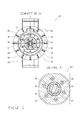
Figur 1 Figur 7- eine perspektivische Ansicht eines Flansches und einer Welle, die Bestandteil der Antriebseinheit gemäß
Figur 1 Figur 8- die Lünette gemäß
Figur 3 Figur 9- die Lünette gemäß
Figur 1
- FIG. 1
- a bezel with three arranged in a common plane holding members, which are deliverable via an axially displaceably held in the housing of the bezel centerpiece in the direction of a workpiece, and with an attached between the center piece and an electric motor
- FIG. 2
- arranged drive unit, through which the middle piece is axially movable, in section and in the starting position, the bezel according to
FIG. 1 , after completion of the feed movement of the three holding members on the workpiece, - FIG. 3
- the bezel according to
FIG. 1 in a clamping position of the three holding members, - FIG. 4
- the bezel according to
FIG. 2 along the section line IV-IV, - FIG. 5
- the lunettes according to
FIG. 3 along the section line VV, - FIG. 6
- the torque curve of the electric motor according to
FIG. 1 for driving the bezel and the distance traveled by the middle piece, - FIG. 7
- a perspective view of a flange and a shaft, which is part of the drive unit according to
FIG. 1 are, in the preassembled state, - FIG. 8
- the bezel according to
FIG. 3 along the section line VIII-VIII and - FIG. 9
- the bezel according to
FIG. 1 , in pre-assembled condition and in perspective view.
In
Des Weiteren weist das Mittelstück 8 zwei nach außen weisende Steuerflächen 9 auf, die spiegelbildlich zueinander gegenüber liegen. Die inneren freien Enden 10 der beiden äußeren Halteglieder 5 und 7 liegen während der Spannbewegung unter Vorspannung an den Steuerflächen 9 an, können allerdings auch andersartig an diese gekoppelt sein, so dass die Steuerfläche 9 und die freien Enden 10 der Halteglieder 5, 7 in ständigem Wirkkontakt miteinander stehen. Sobald demnach das Mittelstück 8 in Richtung auf das Werkstück 4 zugestellt ist, bewegen sich die Halteglieder 5, 6 und 7 derart synchron, dass diese gemeinsam und gleichzeitig mit ihren Werkstückkontaktelementen 11, bspw. Rollen, Gripper, Pads, an dem Werkstück 4 zur Anlage gelangen. Die Bewegung zwischen dem Öffnungswinkel ∝ der beiden äußeren Halteglieder 5 und 7 und der gewünschten Anlage der drei Halteglieder 5, 6 und 7 an dem Werkstück 4 wird als Zustellbewegung oder Eilhub bezeichnet. Nachdem die drei Halteglieder 5, 6 und 7 auf der Oberfläche des Werkstückes 4 anliegen, ist dieses einzuspannen. Die nach der Zustellbewegung zu erfolgende Spannbewegung der drei Halteglieder 5, 6 und 7 ist den
Ausgehend von der in
Der Elektromotor 21 besteht aus einem Stator 22 und einem Rotor bzw. Läufer 23. An dem Rotor 23 ist ein mittels Schrauben 25 befestigter Flansch 24 angebracht. Der Flansch 24 weist ein Rohrstück auf, in dem eine Innenverzahnung 28 eingearbeitet ist. Die Rotationsbewegung des Rotors 23 wird demnach auf den Flansch 24 und von diesem auf die Welle 26 übertragen.The
Eine Antriebseinheit 61, die im Inneren eines an dem Gehäuse 2 befestigten Antriebseinheitsgehäuse 63 angeordnet ist, ermöglicht nunmehr die Umwandlung der Rotationsbewegung des Elektromotors 21 in eine axiale Zustellbewegung, die auf das Mittelstück 8 einwirkt. Die Antriebseinheit 61 besteht dabei zunächst aus einer Welle 26, die trieblich mit dem Flansch 24 mittels der Innenverzahnung 28 verbunden ist, da auf der Außenseite der Welle 26 eine Außenverzahnung 27 eingearbeitet ist, die in die Innenverzahnung 28 eingreift. Insbesondere
Als weiterer Bestandteil der Antriebseinheit 61 ist eine Hohlwelle 29 anzusehen, die über eine Kupplung 62 in lösbarer formschlüssiger Wirkverbindung mit der Welle 26 während der Zustellbewegung der drei Halteglieder 5, 6 und 7 steht. Die Kupplung 62 kann ohne weiteres als Rutschkupplung ausgebildet sein, so dass eine kraftschlüssige Wirkverbindung zwischen der Welle 26 und der Hohlwelle 29 vorhanden ist, durch die bei übersteigen eines vorgegebenen Drehmomentes die Kraftübertragung gelöst ist.As a further component of the
Die Kupplung 62 wird im Wesentlichen von einem Stift 33 gebildet, der in eine Bohrung 35, die senkrecht zu der Längsachse 3 verläuft und in die Welle 26 eingearbeitet ist, eingesetzt ist. Diese Anordnung kann auch um 90° verdreht sein. Der Stift 33 ist im gezeigten Ausgangszustand gemäß
Fluchtend zu der Längsachse 3 ist in die Welle 26 zudem eine Bohrung 34 vorgesehen, in die eine Schraubendruckfeder 36 eingesetzt ist. An dem dem Stift 33 zugewandten freien Ende der Schraubendruckfeder 36 ist eine Kugel 37 angeordnet, die in eine in den Stift 33 eingearbeitete Kerbe 38 durch die Schraubendruckfeder 36 eingedrückt ist.In alignment with the
Insbesondere aus den
Wenn nunmehr der Elektromotor 21 in Rotation versetzt ist, bewegt sich von der in
In das Mittelstück 8 ist ferner eine Gewindebohrung 13 eingearbeitet, in die eine Gewindespindel 14 eingedreht ist. Die Gewindespindel 14 ist über einen Haltebolzen 16 mit der Hohlwelle 29 fest verbunden. Die konstruktive Ausgestaltung der Hohlwelle 29 ist aus den
Mittels einem in
In
Die Einleitung der Spannbewegung für die drei Halteglieder 5, 6 und 7 ist in
Gleichwohl rotiert die Welle 26 weiter, da der Kraftfluss bzw. das Drehmoment, das von dem Elektromotor 21 zur Verfügung gestellt wird, nicht abgeschaltet ist. Um nunmehr eine axial wirkende Spannbewegung zu erreichen, ist auf der Außenseite der Welle 26 ein Außengewinde 30 eingearbeitet. In die Hohlwelle 29 ist ein Innengewinde 31 vorgesehen. Das Außengewinde 30 der Welle 26 und das Innengewinde 31 der Hohlwelle 29 stehen somit in formschlüssiger Wirkverbindung, und zwar nach Art einer Verzahnung. Sobald die Kupplung 62 zwischen der Welle 26 und der Hohlwelle 29 gelöst ist, rotiert die Welle 26 weiter, so dass eine relative Rotationsbewegung zwischen der Welle 26 und der Hohlwelle 29 über die Innen- und Außengewinde 30 bzw. 31 erfolgt.However, the
Die jeweilige Verschiebung bzw. der zurückgelegte Weg ist in den
Die Welle 26 wird demnach schraubenförmig in Richtung auf das Werkstück 4 zugestellt. An dem freien Ende der Welle 26 ist ein Bolzen 39 vorgesehen. Zwischen der Welle 26 und dem Bolzen 39 besteht eine Anlagefläche. Dies kann insbesondere aus
Der Bolzen 39 weist einen von der Welle 26 abgewandten Bereich 40 auf, der pyramidenförmig ausgestaltet ist. Dabei verjüngt sich die Außenkontur des Bolzens 39 in Richtung auf das Werkstück 4. Das pyramidenförmige freie Ende 40 des Bolzens 39 wirkt als schiefe Ebene, durch die ein auf dem pyramidenförmigen freien Ende 40 angeordneter Kniehebel 41 abgestützt und durch die während der axialen Zustellbewegung des Bolzens 39 eine Spannkraft erzeugt ist, die in Richtung auf das Werkzeug verläuft. In
Der Kniehebel 41 besteht aus einem auf dem pyramidenförmigen freien Ende 40 aufliegenden Gelenk 42, an dem zwei Stege 43 und 44 angebracht sind. Die freien Enden 43' bzw. 44' der Stege 43, 44 sind in der Hohlwelle 29 und in einem Übertragungskörper 15 abgestützt. Zwischen den im Querschnitt rohrförmigen Übertragungskörper 15, der mittels einer Verdrehsicherung 54 an der Außenkontur der Hohlwelle 29 befestigt ist, ist ein Paket von Tellerfedern 45 angeordnet.The
Ein die Hohlwelle 29 umschließendes Lagergehäuse 64 nimmt die Tellerfedern 45 auf, wobei der Übertragungskörper 15 im Inneren der Hohlwelle 29 angeordnet ist. Das Lagergehäuse 64 ist fest mit dem Lünetten-Gehäuse 2 verbunden, wodurch gewährleistet ist, dass die beim Zusammendrücken der Tellerfedern 45 entstehende axial gerichtete Druckkraft zuverlässig abgestützt ist und in Richtung der Längsachse 3, also auf das Werkstück 4, verläuft.A bearing
Des Weiteren ist zwischen dem Bolzen 39 und dem Übertragungskörper 15 eine Schraubendruckfeder 46 vorgesehen, durch die eine Rückstellkraft auf den Bolzen 39 ausgeübt wird, sobald der Einspannzustand für das Werkstück 4 freigegeben ist.Furthermore, a
In
Wenn der Spannzustand zwischen dem Werkstück 4 und den drei Haltegliedern 5, 6 und 7 gelöst werden soll, wird die Bewegungsrichtung des Elektromotors 21 umgeschaltet, so dass dieser in entgegen gesetzter Richtung bezüglich der Antriebs- bzw. Spannrichtung rotiert. Durch diese Maßnahme wird zunächst über den Flansch 24 die Welle 26 in Richtung einen das Antriebseinheitsgehäuse 63 verschließenden Deckels 18 zurückgedreht, und zwar so lange, bis der Stift 33 in die Vertiefung 32 aufgrund der von der Schraubendruckfeder 36 ausgeübten Rückstellkraft einrastet und somit über die Kupplung 62 erneut eine formschlüssige Wirkverbindung zwischen der Welle 26 und der Hohlwelle 29 besteht. Durch die in der Hohlwelle 29 angeordnete Schraubendruckfeder 46 wird der Bolzen 39 in Richtung des Deckels 18 zurückgestellt, so dass der Kniehebel 41 entlang des pyramidenförmigen freien Endes 40 zurück in seine Ausgangsposition bewegt und die Spannkraft der Tellerfeder 45 reduziert ist.If the clamping state between the
Sobald die Kupplung 62 die formschlüssige Wirkverbindung zwischen der Welle 26 und der Hohlwelle 29 erreicht hat, wird über die Hohlwelle 29 die Gewindespindel 14 in Rotation versetzt, so dass das Mittelstück 8 von dem Werkstück 4 wegbewegt wird, wodurch die drei Halteglieder 5, 6 und 7 aufschwenken und somit das Werkstück 4 freigeben.As soon as the
Der Vollständigkeit halber werden auf konstruktive Maßnahmen zur Lagerung der Antriebseinheit 61 auf ein Festlager 19 und ein Loslager 20 verwiesen, durch die die Rotationskräfte, die durch das Lagergehäuse 64 auftreten, an das Antriebseinheitsgehäuse 63 weitergegeben werden. Des Weiteren ist in Umfangsrichtung der Hohlwelle 29 eine weitere Schraubendruckfeder 47 vorgesehen, durch die zusätzlich eine Rückstellkraft, die auf den Kniehebel 41 einwirkt, erzeugt ist.For the sake of completeness, reference is made to constructive measures for mounting the
Der Elektromotor 21 treibt folglich die Antriebseinheit 61 mit einer konstanten Rotationsgeschwindigkeit, und zwar sowohl während der Zustell- als auch während der Spannbewegung der drei Halteglieder 5, 6 und 7 an. Dadurch, dass die zwischen der Welle 26 und der Hohlwelle 29 eingebaute Kupplung 62 diese konstante Rotationsgeschwindigkeit überträgt, dreht die Gewindespindel 14 aus dem Verhältnis dieser Rotationsgeschwindigkeit und der Steigung des Trapezgewindes 30, so dass das Mittelstück 8 axial in Richtung auf das Werkstück 4 mit einer konstanten vorgegebenen Geschwindigkeit zubewegt ist. Dies ist als erste Zustellgeschwindigkeit des Mittelstückes 8 zu verstehen.The
Sobald die Rollen 11 der drei Halteglieder 5, 6 und 7 die Oberfläche des Werkstückes 4 erreichen, steigt das Drehmoment, wie vorstehend erläutert, an, so dass die formschlüssige Wirkverbindung der Kupplung 62 zwischen der Welle 26 und der Hohlwelle 29 gelöst ist.As soon as the
Die Welle 26 ist weiterhin in Rotation versetzt und bewegt sich durch die Entkupplung mit der Hohlwelle 29 schraubenförmig relativ zu dieser in Richtung auf das Werkstück 4 und übt dabei eine axial gerichtete Druckkraft auf den Bolzen 39 aus, der folglich dadurch in Längsrichtung 3 auf das Werkstück 4 verschoben ist. Somit werden die beiden gegenüberliegenden Kniehebel 41 aufgeweitet, denn das Gelenk 42 rutscht über das pyramidenförmige freie Ende 40 des Bolzens 39 nach außen. Diese durch den Kniehebel 41 und die axiale Bewegung der Welle 26 erzeugte Spannbewegung ist als zweite Zustellgeschwindigkeit des Mittelstückes 8 anzusehen.The
Auch wenn das Mittelstück 8 lediglich geringfügig in Richtung auf das Werkstück 4 bewegt wird und die zweite Zustellgeschwindigkeit gegen null geht, ist eine solche vorhanden. Durch diese ist nämlich die Zustellkraft Fz erzeugt. Dies bedeutet, rein physikalisch, dass durch die erste Zustellgeschwindigkeit eine Zustellkraft Fz auf das Mittelstück 8 übertragen wird, wobei die Zustellkraft Fz gegen null geht, da die Bewegungen des Mittelstückes 8 in Längsrichtung 3 nicht behindert sind. Wenn dagegen das Mittelstück 8 in Richtung auf das Werkstück 4 nicht mehr axial beweglich ist, sinkt die zweite Zustellgeschwindigkeit gegen null, wodurch die Spannkraft Fs mittels der eingebauten Tellerfedern 45 aufgebaut ist.Even if the
Ausgehend von der Übergangsposition zwischen der Zustell- und der Spannbewegung des Mittelstückes 8 kann errechnet werden, wie viele Umdrehungen der Elektromotor 21 auszuführen hat, um eine vorgegebene Spannkraft Fs durch die drei Halteglieder 5, 6 und 7 auf das Werkstück 4 zu übertragen, da die Spannkraft aus den vorgegebenen Federkernlinien der Tellerfedern 45 und dem zurückgelegten axialen Weg des Bolzens 39 errechnet werden kann.Starting from the transition position between the infeed and the tensioning movement of the
Claims (14)
dadurch gekennzeichnet,
dass die Antriebseinheit (61) durch einen Elektromotor (21) antreibbar ist, dass die Rotationsbewegungen des Elektromotors (21) durch die Antriebseinheit (61) in mindestens zwei unterschiedliche axiale Zustellgeschwindigkeiten des Mittelstückes (8) mit daraus resultierenden auf das Werkstück (4) gerichteten Kraftbeträgen (Fz, Fs) umwandelbar sind, und dass zur Einstellung der jeweiligen Zustellgeschwindigkeit des Mittelstücke (8) zwischen diesem und dem Elektromotor (21) eine zwangläufig wirksame Kupplung (62) eingesetzt ist, mittels der die Antriebseinheit (61) in zwei unterschiedliche Schaltstellungen selbsttätig umschaltbar ist.Self-centering steady rest (1) for clamping and / or holding a workpiece (4) on a lathe, with three holding elements (5, 6, 7) mounted in a housing (2) of the steady rest (1) and held in a common plane. of which the two outer holding members (5, 7) are designed as a mirror image mutually pivotable in the housing (2) supported angle lever and the middle holding member (6) by a drive unit (61) and a drivingly connected to this centerpiece (8) axially in the direction of the workpiece (4) is guided displaceably in the housing (2), wherein on the central piece (8) control surface (9) are provided with which the two outer holding members (5, 7) by means of their inner ends (10 ) interact,
characterized,
in that the drive unit (61) can be driven by an electric motor (21) that the rotational movements of the electric motor (21) by the drive unit (61) in at least two different axial delivery speeds of the center piece (8) with resulting on the workpiece (4) Force amounts (F z , F s ) are convertible, and that for setting the respective feed rate of the center pieces (8) between the latter and the electric motor (21) a positively effective coupling (62) is inserted, by means of which the drive unit (61) in two different switching positions can be switched automatically.
dadurch gekennzeichnet,
dass die Antriebseinheit (61) aus einer Welle (26) und eine die Welle (26) bereichsweise in deren Längsrichtung (3) umgreifende Hohlwelle (29) besteht und dass die Welle (26) und die Hohlwelle (29) mittels der Kupplung (62) in kraftschlüssiger oder lösbar formschlüssiger Wirkverbindung stehen.Bezel according to claim 1,
characterized,
in that the drive unit (61) consists of a shaft (26) and a hollow shaft (29) encompassing the shaft (26) in certain areas in its longitudinal direction (3) and that the shaft (26) and the hollow shaft (29) are connected by means of the coupling (62 ) are in non-positive or releasable form-fitting operative connection.
dadurch gekennzeichnet,
dass die Kupplung (62) als federbelasteter Stift (33) ausgebildet ist, dass der Stift (33) in einer, vorzugsweise senkrecht zu der Längsachse (3) der Lünette (1) ausgerichteten, in der Welle (26) eingearbeiteten Bohrung (35) angeordnet ist und dass in der Innenseite der Hohlwelle (29) eine Vertiefung (32) vorgesehen ist, in die der Stift (33) während der Zustell- und Rückführbewegung der drei Halteglieder (5, 6, 7) eingreift und dass der Stift (33) aus der Vertiefung (32), während die Halteglieder (5, 6, 7) das Werkstück (4) einspannen, ausgefahren ist.Bezel according to claim 2,
characterized,
in that the coupling (62) is designed as a spring-loaded pin (33), in that the pin (33) is aligned in a bore (35) which is aligned in the shaft (26), preferably perpendicular to the longitudinal axis (3) of the steady rest (1). is arranged and that in the inside of the hollow shaft (29) has a recess (32) is provided, in which the pin (33) during the feed and return movement of the three holding members (5, 6, 7) engages and that the pin (33 ) from the recess (32) while the holding members (5, 6, 7) clamp the workpiece (4) is extended.
dadurch gekennzeichnet,
dass senkrecht zu dem Stift (33) eine Bohrung (34) vorgesehen ist, in die eine Schraubendruckfeder (36) eingesetzt ist, dass die Schraubendruckfeder (36) mit ihrem freien Ende in eine in dem Stift (33) eingearbeitete Kerbe (38) gehalten ist und dass durch die Schraubendruckfeder (36) der Stift (33) unter Vorspannung in die Vertiefung (32) der Hohlwelle (29) eingedrückt ist.Bezel according to claim 3,
characterized,
in that a bore (34) is provided perpendicular to the pin (33), in which a helical compression spring (36) is inserted, holding the helical compression spring (36) with its free end in a notch (38) machined in the pin (33) is and that by the helical compression spring (36) of the pin (33) is pressed under bias in the recess (32) of the hollow shaft (29).
dadurch gekennzeichnet,
dass die Vertiefung (32) eine in Antriebsrotationsrichtung des Elektromotors (21) angeordnete schräge Fläche (32') aufweist, auf der der Stift (33) aufliegt, und dass die zu der schrägen Fläche (32') gegenüberliegende Wand der Vertiefung (32) radial verläuft.Bezel according to claim 4,
characterized,
in that the depression (32) has an inclined surface (32 ') arranged in the drive rotational direction of the electric motor (21), on which the pin (33) rests, and in that the wall of the depression (32) opposite the oblique surface (32') extends radially.
dadurch gekennzeichnet,
dass auf der Außenkontur der Welle (26) ein Gewinde (30), vorzugsweise ein Trapezgewinde, eingearbeitet ist und dass in die Innenseite der Hohlwelle (29) ein mit dem Trapezgewinde (30) der Welle (26) korrespondierendes Innengewinde (31) vorgesehen ist, die relativ zueinander in Abhängigkeit von der Position der Kupplung (62) bewegbar sind.Bezel according to claim 3,
characterized,
in that a thread (30), preferably a trapezoidal thread, is machined on the outer contour of the shaft (26) and that an internal thread (31) corresponding to the trapezoidal thread (30) of the shaft (26) is provided in the inside of the hollow shaft (29) which are movable relative to each other depending on the position of the coupling (62).
dadurch gekenntzeichnet,
dass die Welle (26) an einem Bolzen (39) plan anliegt, der fluchtend zu der Längsachse (3) der Lünette (1) verläuft, und dass das der Welle (26) gegenüberliegende freie Ende (40) des Bolzens (39) als sich in Richtung auf das Werkstück (4) verjüngende pyramidenförmige Anlagefläche ausgestaltet ist.Lunette according to one of the preceding claims,
characterized thereby,
in that the shaft (26) rests flat against a bolt (39) which is aligned with the longitudinal axis (3) of the steady rest (1) and that the free end (40) of the bolt (39) opposite the shaft (26) in the direction of the workpiece (4) tapered pyramidal contact surface is configured.
dadurch gekennzeichnet,
dass auf der Außenseite der pyramidenförmigen Ebene (40) des Bolzens (39) mindestens ein Kniehebel (41) vorgesehen ist, die vorzugsweise paarweise gegenüberliegend zueinander angeordnet sind, dass zur Aufnahme des jeweiligen Kniehebels (41) in die Hohlwelle (29) eine Aussparung (50) eingearbeitet ist und dass die freien Enden (43') des jeweiligen Kniehebel (41) in einem dem Elektromotor (21) zugeordneten Lagergehäuses (64) angeordnet sind, in das ein Übertragungskörper (15) eingesetzt ist, und dass das dazu gegenüberliegende freie Ende (44') des Kniehebels (41) in der Hohlwelle (29) abgestützt ist, die mit einer mit dem Mittelstück (8) trieblich verbundenen Gewindespindel (14) in kraft- oder formschlüssiger Wirkverbindung steht.Bezel according to claim 7,
characterized,
in that at least one toggle lever (41) is provided on the outside of the pyramidal plane (40) of the bolt (39), preferably in pairs opposite one another are arranged to each other, that for receiving the respective knee lever (41) in the hollow shaft (29) has a recess (50) is incorporated and that the free ends (43 ') of the respective toggle lever (41) in a the electric motor (21) associated bearing housing (64) are arranged, in which a transmission body (15) is inserted, and that the opposite free end (44 ') of the toggle lever (41) in the hollow shaft (29) is supported, which is connected to one with the center piece (8). drivingly connected threaded spindle (14) is in non-positive or positive operative connection.
dadurch gekennzeichnet,
dass zwischen dem Bolzen (39) und der Gewindespindel (14) eine in diesem eingesetzte Schraubendruckfeder (46) angeordnet ist, durch die der Bolzen (39) mit einer in Richtung der Welle (26) wirkenden Rückstellkraft beaufschlagt ist.Bezel according to claim 8,
characterized,
in that a helical compression spring (46) inserted therein is arranged between the bolt (39) and the threaded spindle (14), by means of which the bolt (39) is acted upon by a restoring force acting in the direction of the shaft (26).
dadurch gekennzeichnet,
dass das Mittelstück (8) in dem Gehäuse (2) der Lünette (1) axial verschiebbar und drehfest gehalten ist, und dass fluchtend zu der Längsachse (3) der Lünette (1) in das Mittelstück (8) eine Gewindebohrung (13) eingearbeitet ist, in die eine Gewindespindel (14) eingreift, dass die Gewindespindel (14) über einen senkrecht zu der Längsachse (3) der Lünette (1) verlaufenden Haltebolzen (16) an der Hohlwelle (29) befestigt ist, und dass zwischen einem dem Elektromotor (21) zugeordnetes Lagergehäuse (64) und der Hohlwelle (29), mindestens ein in einer in die Hohlwelle (29) eingearbeiteten Aussparung (50) eingesetzter Kniehebels (41) angeordnet ist, der an der Hohlwelle (29) und an einem dem Lagergehäuse (64) zugeordneten Übertragungskörper (15) mit seinen freien Enden (43, 44) anliegt.Lunettes according to one of the preceding claims 1 to 7,
characterized,
in that the middle piece (8) in the housing (2) of the steady rest (1) is held axially displaceable and non-rotatably, and that a threaded bore (13) is incorporated in the middle piece (8) in alignment with the longitudinal axis (3) of the steady rest (1) is, in which a threaded spindle (14) engages that the threaded spindle (14) via a perpendicular to the longitudinal axis (3) of the bezel (1) extending retaining pin (16) is fixed to the hollow shaft (29), and that between a the Electric motor (21) associated bearing housing (64) and the hollow shaft (29), at least one in a hollow shaft (29) incorporated recess (50) inserted toggle lever (41) is arranged on the hollow shaft (29) and at a Bearing housing (64) associated transmission body (15) with its free ends (43, 44) rests.
dadurch gekennzeichnet,
dass zwischen der Welle (26) und einem Flansch (24), der drehfest mit dem Elektromotor (2) und der Welle (26) verbunden ist, eine axial verschiebliche Wirkverbindung besteht, und dass die Welle (26) parallel zu der Längsachse (3) der Lünette (1) entlang der Innenkontur des Flansches (24) geführt gehalten ist.Lunette according to one of the preceding claims,
characterized,
in that there is an axially displaceable operative connection between the shaft (26) and a flange (24) which is non-rotatably connected to the electric motor (2) and the shaft (26), and that the shaft (26) is parallel to the longitudinal axis (3 ) of the steady rest (1) is guided guided along the inner contour of the flange (24).
dadurch gekennzeichnet,
dass der Elektromotor (21) koaxial oder fluchtend zu der Längsachse (3) der Lünette (1) neben dem Gehäuse (2) angeordnet ist und dass der Elektromotor (21) die Antriebseinheit (61), zumindest teilweise, in deren Umfangsrichtung umgreift.Lunette according to one of the preceding claims,
characterized,
in that the electric motor (21) is arranged coaxially or in alignment with the longitudinal axis (3) of the steady rest (1) next to the housing (2) and that the electric motor (21) surrounds, at least partially, the drive unit (61) in its circumferential direction.
dadurch gekennzeichnet,
dass zwischen dem Lagergehäuse (64) und dem ersten freien Ende (43) des Kniehebels (41) eine oder mehrere Tellerfedern (45) angeordnet sind, durch die eine vorbestimmte Spannkraft auf die drei Halteglieder (5, 6, 7) während des Spannzustandes (Fz) ausgeübt ist.Bezel according to claim 8 or 10,
characterized,
in that between the bearing housing (64) and the first free end (43) of the toggle lever (41) one or more disc springs (45) are arranged, by which a predetermined clamping force on the three holding members (5, 6, 7) during the clamping state ( F z ) is exercised.
dadurch gekennzeichnet,
dass der Antriebswelle (26) und dem Elektromotor (21) ein Winkelmesser (51) und eine Steuerelektronik zugeordnet sind und dass die Rotationsgeschwindigkeit des Elektromotors (21) durch die Steuerelektronik reduziert ist unmittelbar vor Erreichen des Anschlages zwischen den drei Haltegliedern (5, 6, 7) und dem Werkstück (4), und/oder dass durch die Winkelmessung des Elektromotors (21) eine Kraftsteuerung (Fz) oder eine Wegmessung des Mittelstücke (8) ermöglicht ist, durch die die Anzahl der Rotationen des Elektromotors (21) während der Spannbewegung (Fz) einstellbar ist.Lunette according to one of the preceding claims,
characterized,
in that the drive shaft (26) and the electric motor (21) are associated with a goniometer (51) and control electronics and that the rotational speed of the electric motor (21) is reduced by the control electronics immediately before reaching the stop between the three holding members (5, 6, 7) and the workpiece (4), and / or that by the angle measurement of the electric motor (21) a force control (F z ) or a displacement measurement of the center pieces (8) is made possible the number of rotations of the electric motor (21) during the clamping movement (F z ) is adjustable.
Priority Applications (8)
| Application Number | Priority Date | Filing Date | Title |
|---|---|---|---|
| AT10152923T ATE537935T1 (en) | 2010-02-08 | 2010-02-08 | SELF-CENTERING BEZEL |
| PL10152923T PL2353777T3 (en) | 2010-02-08 | 2010-02-08 | Self-centring support |
| EP10152923A EP2353777B1 (en) | 2010-02-08 | 2010-02-08 | Self-centring support |
| TW100100037A TWI510324B (en) | 2010-02-08 | 2011-01-03 | Self-centring steady rest |
| KR1020110008188A KR101475553B1 (en) | 2010-02-08 | 2011-01-27 | Self-centering steady rest |
| CN201110037118.8A CN102152136B (en) | 2010-02-08 | 2011-01-30 | Self-centring support |
| US12/931,570 US8726772B2 (en) | 2010-02-08 | 2011-02-04 | Self-centering steady rest |
| JP2011023796A JP5593249B2 (en) | 2010-02-08 | 2011-02-07 | Self-aligning fixed steady rest |
Applications Claiming Priority (1)
| Application Number | Priority Date | Filing Date | Title |
|---|---|---|---|
| EP10152923A EP2353777B1 (en) | 2010-02-08 | 2010-02-08 | Self-centring support |
Publications (2)
| Publication Number | Publication Date |
|---|---|
| EP2353777A1 true EP2353777A1 (en) | 2011-08-10 |
| EP2353777B1 EP2353777B1 (en) | 2011-12-21 |
Family
ID=42244188
Family Applications (1)
| Application Number | Title | Priority Date | Filing Date |
|---|---|---|---|
| EP10152923A Active EP2353777B1 (en) | 2010-02-08 | 2010-02-08 | Self-centring support |
Country Status (8)
| Country | Link |
|---|---|
| US (1) | US8726772B2 (en) |
| EP (1) | EP2353777B1 (en) |
| JP (1) | JP5593249B2 (en) |
| KR (1) | KR101475553B1 (en) |
| CN (1) | CN102152136B (en) |
| AT (1) | ATE537935T1 (en) |
| PL (1) | PL2353777T3 (en) |
| TW (1) | TWI510324B (en) |
Cited By (5)
| Publication number | Priority date | Publication date | Assignee | Title |
|---|---|---|---|---|
| EP2546023A1 (en) * | 2011-07-13 | 2013-01-16 | Röhm GmbH | Rest with electric drive |
| EP2711124A1 (en) | 2012-09-21 | 2014-03-26 | ADVO-Carillon UG (haftungsbeschränkt) | Self-centring support |
| EP2632639B1 (en) | 2011-09-19 | 2016-04-06 | Ludwig Ehrhardt GmbH | Clamping device with an electric motor |
| DE102019119610A1 (en) * | 2019-07-19 | 2020-08-27 | Schaeffler Technologies AG & Co. KG | Apparatus and method for shoe grinding |
| CN115747411A (en) * | 2022-11-07 | 2023-03-07 | 中冶东方工程技术有限公司 | Converter oxygen lance centering device |
Families Citing this family (14)
| Publication number | Priority date | Publication date | Assignee | Title |
|---|---|---|---|---|
| KR101113455B1 (en) * | 2011-11-25 | 2012-02-24 | 이창옥 | Vibration absorber for turning machining |
| KR101505170B1 (en) * | 2012-06-19 | 2015-03-24 | 서보산업 주식회사 | The System Supporter |
| US9114490B1 (en) | 2014-06-30 | 2015-08-25 | Arobotech Systems, Inc. | Adjustable fixture mechanism |
| US9174317B1 (en) * | 2014-08-14 | 2015-11-03 | Arobotech Systems, Inc. | Adjustable fixture mechanism |
| JP6457277B2 (en) * | 2015-01-23 | 2019-01-23 | Dmg森精機株式会社 | Vibration control device |
| JP6396826B2 (en) * | 2015-02-27 | 2018-09-26 | Dmg森精機株式会社 | Steady rest |
| EP3093103B1 (en) * | 2015-05-12 | 2017-07-12 | SMW-Autoblok Spannsysteme GmbH | Stationary support |
| EP3093102B1 (en) * | 2015-05-12 | 2017-09-27 | SMW-Autoblok Spannsysteme GmbH | Stationary support |
| DE102015115205A1 (en) * | 2015-09-10 | 2017-03-16 | Walter Maschinenbau Gmbh | Actuator for a steady rest |
| EP3254801B1 (en) * | 2016-06-09 | 2019-04-03 | SMW-AUTOBLOK Spannsysteme GmbH | Stationary support with a force measuring device |
| US9839985B1 (en) | 2017-03-10 | 2017-12-12 | Arobotech Systems, Inc. | Fixture assembly |
| EP3620248B1 (en) * | 2018-09-10 | 2022-06-22 | SMW-Autoblok Spannsysteme GmbH | Coupling device |
| CN111761376A (en) * | 2020-04-21 | 2020-10-13 | 陈云飞 | Self-centering clamp with quick replaceable jaw and supporting roller supporting module |
| CN113458432A (en) * | 2021-07-28 | 2021-10-01 | 珠海镇东有限公司 | Step shaft turning follow rest combined structure and lathe |
Citations (3)
| Publication number | Priority date | Publication date | Assignee | Title |
|---|---|---|---|---|
| DE874548C (en) * | 1951-01-21 | 1953-04-23 | Ludwig Wienand | Self-centering bezel |
| DE3611201A1 (en) | 1985-04-06 | 1986-10-09 | Maschinenfabrik Ravensburg AG, 7980 Ravensburg | Steady rest |
| EP0562180A1 (en) * | 1992-03-21 | 1993-09-29 | SMW-Autoblok Spannsysteme GmbH | Steady rest |
Family Cites Families (16)
| Publication number | Priority date | Publication date | Assignee | Title |
|---|---|---|---|---|
| US3736114A (en) * | 1971-12-06 | 1973-05-29 | Toyoda Machine Works Ltd | Three point contact steady rest |
| GB2089708B (en) * | 1980-12-18 | 1984-02-22 | Index Werke Kg Hahn & Tessky | Steady for holding rod-like circular cross-section components |
| US4399639A (en) * | 1981-05-26 | 1983-08-23 | Lessway Richard J | True centering steady rest |
| US4546681A (en) * | 1982-11-15 | 1985-10-15 | Owsen Paul J | Multi-purpose steady rest |
| DE3544961A1 (en) * | 1985-12-19 | 1987-07-02 | Smw Spanneinrichtungen | SELF-CENTERING LUENETTE |
| JPS63256324A (en) * | 1987-04-13 | 1988-10-24 | Ntn Toyo Bearing Co Ltd | Automatic work rest for long length workpiece machining device |
| JPH0192008A (en) * | 1987-09-30 | 1989-04-11 | Yamazaki Mazak Corp | Work vibration stopper for complex machine tool |
| US5237780A (en) * | 1992-02-04 | 1993-08-24 | Arobotech Systems, Inc. | Steady rest with internal centerline adjustment |
| JPH07102503B2 (en) * | 1992-08-26 | 1995-11-08 | 株式会社エスエムダブリュージャパン | Automatic centering steady rest device for long workpiece cylindrical grinding and grinding method using the device |
| CN2229855Y (en) * | 1995-06-30 | 1996-06-26 | 华中理工大学 | Hydraulic self adapting variable diameter follow-rest |
| JP2000006017A (en) * | 1998-06-25 | 2000-01-11 | Toyoda Mach Works Ltd | Three-point supporting clamper device |
| DE20012710U1 (en) * | 2000-07-22 | 2000-11-23 | Roehm Gmbh | Bezel |
| US6699113B2 (en) * | 2001-10-12 | 2004-03-02 | Arobotech Systems, Inc. | Steady rest with vertical adjustment |
| CN200967089Y (en) * | 2006-10-17 | 2007-10-31 | 华中科技大学 | Self-centering center frame |
| CN201324945Y (en) * | 2008-11-21 | 2009-10-14 | 四川长征机床集团有限公司 | Self-centering center frame |
| EP2191932A1 (en) * | 2008-11-28 | 2010-06-02 | SMW-AUTOBLOK Spannsysteme GmbH | Stationary support |
-
2010
- 2010-02-08 PL PL10152923T patent/PL2353777T3/en unknown
- 2010-02-08 EP EP10152923A patent/EP2353777B1/en active Active
- 2010-02-08 AT AT10152923T patent/ATE537935T1/en active
-
2011
- 2011-01-03 TW TW100100037A patent/TWI510324B/en active
- 2011-01-27 KR KR1020110008188A patent/KR101475553B1/en active IP Right Grant
- 2011-01-30 CN CN201110037118.8A patent/CN102152136B/en active Active
- 2011-02-04 US US12/931,570 patent/US8726772B2/en active Active
- 2011-02-07 JP JP2011023796A patent/JP5593249B2/en active Active
Patent Citations (4)
| Publication number | Priority date | Publication date | Assignee | Title |
|---|---|---|---|---|
| DE874548C (en) * | 1951-01-21 | 1953-04-23 | Ludwig Wienand | Self-centering bezel |
| DE3611201A1 (en) | 1985-04-06 | 1986-10-09 | Maschinenfabrik Ravensburg AG, 7980 Ravensburg | Steady rest |
| EP0562180A1 (en) * | 1992-03-21 | 1993-09-29 | SMW-Autoblok Spannsysteme GmbH | Steady rest |
| EP0562180B1 (en) | 1992-03-21 | 1995-11-02 | SMW-Autoblok Spannsysteme GmbH | Steady rest |
Cited By (7)
| Publication number | Priority date | Publication date | Assignee | Title |
|---|---|---|---|---|
| EP2546023A1 (en) * | 2011-07-13 | 2013-01-16 | Röhm GmbH | Rest with electric drive |
| EP2632639B1 (en) | 2011-09-19 | 2016-04-06 | Ludwig Ehrhardt GmbH | Clamping device with an electric motor |
| EP2711124A1 (en) | 2012-09-21 | 2014-03-26 | ADVO-Carillon UG (haftungsbeschränkt) | Self-centring support |
| DE102012217001A1 (en) | 2012-09-21 | 2014-03-27 | ADVO-Carillon UG (haftungsbeschränkt) | Self-centering bezel |
| DE102019119610A1 (en) * | 2019-07-19 | 2020-08-27 | Schaeffler Technologies AG & Co. KG | Apparatus and method for shoe grinding |
| CN115747411A (en) * | 2022-11-07 | 2023-03-07 | 中冶东方工程技术有限公司 | Converter oxygen lance centering device |
| CN115747411B (en) * | 2022-11-07 | 2023-12-01 | 中冶东方工程技术有限公司 | Converter oxygen rifle centering device |
Also Published As
| Publication number | Publication date |
|---|---|
| CN102152136A (en) | 2011-08-17 |
| JP2011161627A (en) | 2011-08-25 |
| KR101475553B1 (en) | 2014-12-22 |
| KR20110092216A (en) | 2011-08-17 |
| TW201127543A (en) | 2011-08-16 |
| JP5593249B2 (en) | 2014-09-17 |
| EP2353777B1 (en) | 2011-12-21 |
| TWI510324B (en) | 2015-12-01 |
| PL2353777T3 (en) | 2012-07-31 |
| ATE537935T1 (en) | 2012-01-15 |
| US20110209591A1 (en) | 2011-09-01 |
| US8726772B2 (en) | 2014-05-20 |
| CN102152136B (en) | 2015-09-23 |
Similar Documents
| Publication | Publication Date | Title |
|---|---|---|
| EP2353777B1 (en) | Self-centring support | |
| EP2837466B1 (en) | Clamping unit, in particular for use in a machining centre or a turning or milling center | |
| DE3714562A1 (en) | TOOL SPINDLE ARRANGEMENT WITH AN ELECTRIC DRIVE MOTOR | |
| DE10114480C2 (en) | Swivel actuator with three stop positions | |
| DE102008003125B4 (en) | Power operated vise | |
| DE102016011301B4 (en) | Electronic disc brake | |
| DE102007032608B4 (en) | Method and device for centering and clamping a workpiece in a balancing machine | |
| DE2812045A1 (en) | MOTOR SCREWDRIVER WITH SLIP CLUTCH | |
| DE3603618C1 (en) | Clamping device for use on machine tools | |
| DE19845024A1 (en) | Power driven screwdriver | |
| DE1812325A1 (en) | Mechanical clamping device, in particular machine vice | |
| DE2617610A1 (en) | FORCE-OPERATED TORQUE TOOL | |
| WO2016058899A1 (en) | Collet chuck for coupling a tool adapter to a motor spindle of a machine tool | |
| EP1992436B1 (en) | Motor-driven working spindle for a machine tool | |
| DE4325739A1 (en) | Switching device for multi-stage manual transmission | |
| DE4131273C1 (en) | ||
| DE2805881A1 (en) | CLAMPING PIN FOR COAXIAL MACHINING OF WORKPIECES WITH INTERNAL GEAR | |
| DE102005010211A1 (en) | Parking lock mechanism for use in motor vehicle, has casing radially arranged between connection rod and blocking device that is arranged on outer diameter of casing and is not spring-mounted and not pre-stressed and freely rotated | |
| EP2837450B1 (en) | Clamping device | |
| DE3911073C1 (en) | ||
| DE4005181C1 (en) | Machine tool work spindle drive - has angularly adjustable motor with spur gearing controlled via pawl | |
| EP3822008B1 (en) | Spindle assembly for a machine tool | |
| EP4006257B1 (en) | Shading device | |
| DE4025745C2 (en) | ||
| DE102011006367B3 (en) | Clamping device and workpiece spindle with a clamping device |
Legal Events
| Date | Code | Title | Description |
|---|---|---|---|
| PUAI | Public reference made under article 153(3) epc to a published international application that has entered the european phase |
Free format text: ORIGINAL CODE: 0009012 |
|
| AK | Designated contracting states |
Kind code of ref document: A1 Designated state(s): AT BE BG CH CY CZ DE DK EE ES FI FR GB GR HR HU IE IS IT LI LT LU LV MC MK MT NL NO PL PT RO SE SI SK SM TR |
|
| AX | Request for extension of the european patent |
Extension state: AL BA RS |
|
| 17P | Request for examination filed |
Effective date: 20100810 |
|
| GRAP | Despatch of communication of intention to grant a patent |
Free format text: ORIGINAL CODE: EPIDOSNIGR1 |
|
| RIC1 | Information provided on ipc code assigned before grant |
Ipc: B23Q 1/76 20060101AFI20110808BHEP |
|
| GRAS | Grant fee paid |
Free format text: ORIGINAL CODE: EPIDOSNIGR3 |
|
| GRAA | (expected) grant |
Free format text: ORIGINAL CODE: 0009210 |
|
| AK | Designated contracting states |
Kind code of ref document: B1 Designated state(s): AT BE BG CH CY CZ DE DK EE ES FI FR GB GR HR HU IE IS IT LI LT LU LV MC MK MT NL NO PL PT RO SE SI SK SM TR |
|
| REG | Reference to a national code |
Ref country code: GB Ref legal event code: FG4D Free format text: NOT ENGLISH |
|
| REG | Reference to a national code |
Ref country code: CH Ref legal event code: EP |
|
| REG | Reference to a national code |
Ref country code: AT Ref legal event code: REF Ref document number: 537935 Country of ref document: AT Kind code of ref document: T Effective date: 20120115 |
|
| REG | Reference to a national code |
Ref country code: IE Ref legal event code: FG4D |
|
| REG | Reference to a national code |
Ref country code: SE Ref legal event code: TRGR |
|
| REG | Reference to a national code |
Ref country code: DE Ref legal event code: R096 Ref document number: 502010000275 Country of ref document: DE Effective date: 20120315 |
|
| REG | Reference to a national code |
Ref country code: NL Ref legal event code: VDEP Effective date: 20111221 |
|
| PG25 | Lapsed in a contracting state [announced via postgrant information from national office to epo] |
Ref country code: LT Free format text: LAPSE BECAUSE OF FAILURE TO SUBMIT A TRANSLATION OF THE DESCRIPTION OR TO PAY THE FEE WITHIN THE PRESCRIBED TIME-LIMIT Effective date: 20111221 Ref country code: NO Free format text: LAPSE BECAUSE OF FAILURE TO SUBMIT A TRANSLATION OF THE DESCRIPTION OR TO PAY THE FEE WITHIN THE PRESCRIBED TIME-LIMIT Effective date: 20120321 |
|
| LTIE | Lt: invalidation of european patent or patent extension |
Effective date: 20111221 |
|
| PG25 | Lapsed in a contracting state [announced via postgrant information from national office to epo] |
Ref country code: GR Free format text: LAPSE BECAUSE OF FAILURE TO SUBMIT A TRANSLATION OF THE DESCRIPTION OR TO PAY THE FEE WITHIN THE PRESCRIBED TIME-LIMIT Effective date: 20120322 Ref country code: SI Free format text: LAPSE BECAUSE OF FAILURE TO SUBMIT A TRANSLATION OF THE DESCRIPTION OR TO PAY THE FEE WITHIN THE PRESCRIBED TIME-LIMIT Effective date: 20111221 Ref country code: LV Free format text: LAPSE BECAUSE OF FAILURE TO SUBMIT A TRANSLATION OF THE DESCRIPTION OR TO PAY THE FEE WITHIN THE PRESCRIBED TIME-LIMIT Effective date: 20111221 Ref country code: HR Free format text: LAPSE BECAUSE OF FAILURE TO SUBMIT A TRANSLATION OF THE DESCRIPTION OR TO PAY THE FEE WITHIN THE PRESCRIBED TIME-LIMIT Effective date: 20111221 Ref country code: NL Free format text: LAPSE BECAUSE OF FAILURE TO SUBMIT A TRANSLATION OF THE DESCRIPTION OR TO PAY THE FEE WITHIN THE PRESCRIBED TIME-LIMIT Effective date: 20111221 |
|
| PG25 | Lapsed in a contracting state [announced via postgrant information from national office to epo] |
Ref country code: CY Free format text: LAPSE BECAUSE OF FAILURE TO SUBMIT A TRANSLATION OF THE DESCRIPTION OR TO PAY THE FEE WITHIN THE PRESCRIBED TIME-LIMIT Effective date: 20111221 |
|
| REG | Reference to a national code |
Ref country code: IE Ref legal event code: FD4D |
|
| PG25 | Lapsed in a contracting state [announced via postgrant information from national office to epo] |
Ref country code: IS Free format text: LAPSE BECAUSE OF FAILURE TO SUBMIT A TRANSLATION OF THE DESCRIPTION OR TO PAY THE FEE WITHIN THE PRESCRIBED TIME-LIMIT Effective date: 20120421 Ref country code: BG Free format text: LAPSE BECAUSE OF FAILURE TO SUBMIT A TRANSLATION OF THE DESCRIPTION OR TO PAY THE FEE WITHIN THE PRESCRIBED TIME-LIMIT Effective date: 20120321 Ref country code: CZ Free format text: LAPSE BECAUSE OF FAILURE TO SUBMIT A TRANSLATION OF THE DESCRIPTION OR TO PAY THE FEE WITHIN THE PRESCRIBED TIME-LIMIT Effective date: 20111221 Ref country code: EE Free format text: LAPSE BECAUSE OF FAILURE TO SUBMIT A TRANSLATION OF THE DESCRIPTION OR TO PAY THE FEE WITHIN THE PRESCRIBED TIME-LIMIT Effective date: 20111221 Ref country code: IE Free format text: LAPSE BECAUSE OF FAILURE TO SUBMIT A TRANSLATION OF THE DESCRIPTION OR TO PAY THE FEE WITHIN THE PRESCRIBED TIME-LIMIT Effective date: 20111221 Ref country code: SK Free format text: LAPSE BECAUSE OF FAILURE TO SUBMIT A TRANSLATION OF THE DESCRIPTION OR TO PAY THE FEE WITHIN THE PRESCRIBED TIME-LIMIT Effective date: 20111221 |
|
| REG | Reference to a national code |
Ref country code: PL Ref legal event code: T3 |
|
| BERE | Be: lapsed |
Owner name: SMW-AUTOBLOK SPANNSYSTEME G.M.B.H. Effective date: 20120228 |
|
| PG25 | Lapsed in a contracting state [announced via postgrant information from national office to epo] |
Ref country code: RO Free format text: LAPSE BECAUSE OF FAILURE TO SUBMIT A TRANSLATION OF THE DESCRIPTION OR TO PAY THE FEE WITHIN THE PRESCRIBED TIME-LIMIT Effective date: 20111221 Ref country code: PT Free format text: LAPSE BECAUSE OF FAILURE TO SUBMIT A TRANSLATION OF THE DESCRIPTION OR TO PAY THE FEE WITHIN THE PRESCRIBED TIME-LIMIT Effective date: 20120423 |
|
| PG25 | Lapsed in a contracting state [announced via postgrant information from national office to epo] |
Ref country code: MC Free format text: LAPSE BECAUSE OF NON-PAYMENT OF DUE FEES Effective date: 20120229 |
|
| PLBE | No opposition filed within time limit |
Free format text: ORIGINAL CODE: 0009261 |
|
| STAA | Information on the status of an ep patent application or granted ep patent |
Free format text: STATUS: NO OPPOSITION FILED WITHIN TIME LIMIT |
|
| PG25 | Lapsed in a contracting state [announced via postgrant information from national office to epo] |
Ref country code: DK Free format text: LAPSE BECAUSE OF FAILURE TO SUBMIT A TRANSLATION OF THE DESCRIPTION OR TO PAY THE FEE WITHIN THE PRESCRIBED TIME-LIMIT Effective date: 20111221 |
|
| REG | Reference to a national code |
Ref country code: FR Ref legal event code: ST Effective date: 20121031 |
|
| 26N | No opposition filed |
Effective date: 20120924 |
|
| PG25 | Lapsed in a contracting state [announced via postgrant information from national office to epo] |
Ref country code: BE Free format text: LAPSE BECAUSE OF NON-PAYMENT OF DUE FEES Effective date: 20120228 |
|
| REG | Reference to a national code |
Ref country code: DE Ref legal event code: R097 Ref document number: 502010000275 Country of ref document: DE Effective date: 20120924 |
|
| PG25 | Lapsed in a contracting state [announced via postgrant information from national office to epo] |
Ref country code: FR Free format text: LAPSE BECAUSE OF NON-PAYMENT OF DUE FEES Effective date: 20120229 |
|
| PG25 | Lapsed in a contracting state [announced via postgrant information from national office to epo] |
Ref country code: MK Free format text: LAPSE BECAUSE OF FAILURE TO SUBMIT A TRANSLATION OF THE DESCRIPTION OR TO PAY THE FEE WITHIN THE PRESCRIBED TIME-LIMIT Effective date: 20111221 |
|
| PG25 | Lapsed in a contracting state [announced via postgrant information from national office to epo] |
Ref country code: FI Free format text: LAPSE BECAUSE OF FAILURE TO SUBMIT A TRANSLATION OF THE DESCRIPTION OR TO PAY THE FEE WITHIN THE PRESCRIBED TIME-LIMIT Effective date: 20111221 |
|
| PG25 | Lapsed in a contracting state [announced via postgrant information from national office to epo] |
Ref country code: MT Free format text: LAPSE BECAUSE OF FAILURE TO SUBMIT A TRANSLATION OF THE DESCRIPTION OR TO PAY THE FEE WITHIN THE PRESCRIBED TIME-LIMIT Effective date: 20111221 |
|
| PG25 | Lapsed in a contracting state [announced via postgrant information from national office to epo] |
Ref country code: ES Free format text: LAPSE BECAUSE OF FAILURE TO SUBMIT A TRANSLATION OF THE DESCRIPTION OR TO PAY THE FEE WITHIN THE PRESCRIBED TIME-LIMIT Effective date: 20120401 |
|
| PG25 | Lapsed in a contracting state [announced via postgrant information from national office to epo] |
Ref country code: TR Free format text: LAPSE BECAUSE OF FAILURE TO SUBMIT A TRANSLATION OF THE DESCRIPTION OR TO PAY THE FEE WITHIN THE PRESCRIBED TIME-LIMIT Effective date: 20111221 |
|
| PG25 | Lapsed in a contracting state [announced via postgrant information from national office to epo] |
Ref country code: SM Free format text: LAPSE BECAUSE OF FAILURE TO SUBMIT A TRANSLATION OF THE DESCRIPTION OR TO PAY THE FEE WITHIN THE PRESCRIBED TIME-LIMIT Effective date: 20111221 Ref country code: LU Free format text: LAPSE BECAUSE OF NON-PAYMENT OF DUE FEES Effective date: 20120208 |
|
| PG25 | Lapsed in a contracting state [announced via postgrant information from national office to epo] |
Ref country code: HU Free format text: LAPSE BECAUSE OF FAILURE TO SUBMIT A TRANSLATION OF THE DESCRIPTION OR TO PAY THE FEE WITHIN THE PRESCRIBED TIME-LIMIT Effective date: 20100208 |
|
| REG | Reference to a national code |
Ref country code: CH Ref legal event code: PL |
|
| PG25 | Lapsed in a contracting state [announced via postgrant information from national office to epo] |
Ref country code: LI Free format text: LAPSE BECAUSE OF NON-PAYMENT OF DUE FEES Effective date: 20140228 Ref country code: CH Free format text: LAPSE BECAUSE OF NON-PAYMENT OF DUE FEES Effective date: 20140228 |
|
| REG | Reference to a national code |
Ref country code: AT Ref legal event code: MM01 Ref document number: 537935 Country of ref document: AT Kind code of ref document: T Effective date: 20150208 |
|
| PG25 | Lapsed in a contracting state [announced via postgrant information from national office to epo] |
Ref country code: AT Free format text: LAPSE BECAUSE OF NON-PAYMENT OF DUE FEES Effective date: 20150208 |
|
| REG | Reference to a national code |
Ref country code: DE Ref legal event code: R082 Ref document number: 502010000275 Country of ref document: DE Representative=s name: GEITZ PATENTANWAELTE PARTG MBB, DE Ref country code: DE Ref legal event code: R082 Ref document number: 502010000275 Country of ref document: DE Representative=s name: GEITZ TRUCKENMUELLER LUCHT CHRIST PATENTANWAEL, DE |
|
| PGFP | Annual fee paid to national office [announced via postgrant information from national office to epo] |
Ref country code: SE Payment date: 20230220 Year of fee payment: 14 Ref country code: PL Payment date: 20230130 Year of fee payment: 14 Ref country code: IT Payment date: 20230228 Year of fee payment: 14 Ref country code: GB Payment date: 20230221 Year of fee payment: 14 Ref country code: DE Payment date: 20230216 Year of fee payment: 14 |
|
| P01 | Opt-out of the competence of the unified patent court (upc) registered |
Effective date: 20230527 |