EP2353548A2 - Implantate mit verbesserter Zementhaftung - Google Patents
Implantate mit verbesserter Zementhaftung Download PDFInfo
- Publication number
- EP2353548A2 EP2353548A2 EP11151450A EP11151450A EP2353548A2 EP 2353548 A2 EP2353548 A2 EP 2353548A2 EP 11151450 A EP11151450 A EP 11151450A EP 11151450 A EP11151450 A EP 11151450A EP 2353548 A2 EP2353548 A2 EP 2353548A2
- Authority
- EP
- European Patent Office
- Prior art keywords
- implant
- roughened surface
- value
- cement
- roughened
- Prior art date
- Legal status (The legal status is an assumption and is not a legal conclusion. Google has not performed a legal analysis and makes no representation as to the accuracy of the status listed.)
- Withdrawn
Links
Images


Classifications
-
- A—HUMAN NECESSITIES
- A61—MEDICAL OR VETERINARY SCIENCE; HYGIENE
- A61F—FILTERS IMPLANTABLE INTO BLOOD VESSELS; PROSTHESES; DEVICES PROVIDING PATENCY TO, OR PREVENTING COLLAPSING OF, TUBULAR STRUCTURES OF THE BODY, e.g. STENTS; ORTHOPAEDIC, NURSING OR CONTRACEPTIVE DEVICES; FOMENTATION; TREATMENT OR PROTECTION OF EYES OR EARS; BANDAGES, DRESSINGS OR ABSORBENT PADS; FIRST-AID KITS
- A61F2/00—Filters implantable into blood vessels; Prostheses, i.e. artificial substitutes or replacements for parts of the body; Appliances for connecting them with the body; Devices providing patency to, or preventing collapsing of, tubular structures of the body, e.g. stents
- A61F2/02—Prostheses implantable into the body
- A61F2/30—Joints
- A61F2/30767—Special external or bone-contacting surface, e.g. coating for improving bone ingrowth
- A61F2/30771—Special external or bone-contacting surface, e.g. coating for improving bone ingrowth applied in original prostheses, e.g. holes or grooves
-
- A—HUMAN NECESSITIES
- A61—MEDICAL OR VETERINARY SCIENCE; HYGIENE
- A61F—FILTERS IMPLANTABLE INTO BLOOD VESSELS; PROSTHESES; DEVICES PROVIDING PATENCY TO, OR PREVENTING COLLAPSING OF, TUBULAR STRUCTURES OF THE BODY, e.g. STENTS; ORTHOPAEDIC, NURSING OR CONTRACEPTIVE DEVICES; FOMENTATION; TREATMENT OR PROTECTION OF EYES OR EARS; BANDAGES, DRESSINGS OR ABSORBENT PADS; FIRST-AID KITS
- A61F2/00—Filters implantable into blood vessels; Prostheses, i.e. artificial substitutes or replacements for parts of the body; Appliances for connecting them with the body; Devices providing patency to, or preventing collapsing of, tubular structures of the body, e.g. stents
- A61F2/02—Prostheses implantable into the body
- A61F2/30—Joints
- A61F2/3094—Designing or manufacturing processes
-
- A—HUMAN NECESSITIES
- A61—MEDICAL OR VETERINARY SCIENCE; HYGIENE
- A61F—FILTERS IMPLANTABLE INTO BLOOD VESSELS; PROSTHESES; DEVICES PROVIDING PATENCY TO, OR PREVENTING COLLAPSING OF, TUBULAR STRUCTURES OF THE BODY, e.g. STENTS; ORTHOPAEDIC, NURSING OR CONTRACEPTIVE DEVICES; FOMENTATION; TREATMENT OR PROTECTION OF EYES OR EARS; BANDAGES, DRESSINGS OR ABSORBENT PADS; FIRST-AID KITS
- A61F2/00—Filters implantable into blood vessels; Prostheses, i.e. artificial substitutes or replacements for parts of the body; Appliances for connecting them with the body; Devices providing patency to, or preventing collapsing of, tubular structures of the body, e.g. stents
- A61F2/02—Prostheses implantable into the body
- A61F2/30—Joints
- A61F2/30767—Special external or bone-contacting surface, e.g. coating for improving bone ingrowth
- A61F2002/30906—Special external or bone-contacting surface, e.g. coating for improving bone ingrowth shot- sand- or grit-blasted
-
- A—HUMAN NECESSITIES
- A61—MEDICAL OR VETERINARY SCIENCE; HYGIENE
- A61F—FILTERS IMPLANTABLE INTO BLOOD VESSELS; PROSTHESES; DEVICES PROVIDING PATENCY TO, OR PREVENTING COLLAPSING OF, TUBULAR STRUCTURES OF THE BODY, e.g. STENTS; ORTHOPAEDIC, NURSING OR CONTRACEPTIVE DEVICES; FOMENTATION; TREATMENT OR PROTECTION OF EYES OR EARS; BANDAGES, DRESSINGS OR ABSORBENT PADS; FIRST-AID KITS
- A61F2/00—Filters implantable into blood vessels; Prostheses, i.e. artificial substitutes or replacements for parts of the body; Appliances for connecting them with the body; Devices providing patency to, or preventing collapsing of, tubular structures of the body, e.g. stents
- A61F2/02—Prostheses implantable into the body
- A61F2/30—Joints
- A61F2/30767—Special external or bone-contacting surface, e.g. coating for improving bone ingrowth
- A61F2002/30925—Special external or bone-contacting surface, e.g. coating for improving bone ingrowth etched
-
- A—HUMAN NECESSITIES
- A61—MEDICAL OR VETERINARY SCIENCE; HYGIENE
- A61F—FILTERS IMPLANTABLE INTO BLOOD VESSELS; PROSTHESES; DEVICES PROVIDING PATENCY TO, OR PREVENTING COLLAPSING OF, TUBULAR STRUCTURES OF THE BODY, e.g. STENTS; ORTHOPAEDIC, NURSING OR CONTRACEPTIVE DEVICES; FOMENTATION; TREATMENT OR PROTECTION OF EYES OR EARS; BANDAGES, DRESSINGS OR ABSORBENT PADS; FIRST-AID KITS
- A61F2/00—Filters implantable into blood vessels; Prostheses, i.e. artificial substitutes or replacements for parts of the body; Appliances for connecting them with the body; Devices providing patency to, or preventing collapsing of, tubular structures of the body, e.g. stents
- A61F2/02—Prostheses implantable into the body
- A61F2/30—Joints
- A61F2/46—Special tools or methods for implanting or extracting artificial joints, accessories, bone grafts or substitutes, or particular adaptations therefor
- A61F2002/4631—Special tools or methods for implanting or extracting artificial joints, accessories, bone grafts or substitutes, or particular adaptations therefor the prosthesis being specially adapted for being cemented
-
- A—HUMAN NECESSITIES
- A61—MEDICAL OR VETERINARY SCIENCE; HYGIENE
- A61F—FILTERS IMPLANTABLE INTO BLOOD VESSELS; PROSTHESES; DEVICES PROVIDING PATENCY TO, OR PREVENTING COLLAPSING OF, TUBULAR STRUCTURES OF THE BODY, e.g. STENTS; ORTHOPAEDIC, NURSING OR CONTRACEPTIVE DEVICES; FOMENTATION; TREATMENT OR PROTECTION OF EYES OR EARS; BANDAGES, DRESSINGS OR ABSORBENT PADS; FIRST-AID KITS
- A61F2310/00—Prostheses classified in A61F2/28 or A61F2/30 - A61F2/44 being constructed from or coated with a particular material
- A61F2310/00005—The prosthesis being constructed from a particular material
- A61F2310/00011—Metals or alloys
- A61F2310/00023—Titanium or titanium-based alloys, e.g. Ti-Ni alloys
-
- A—HUMAN NECESSITIES
- A61—MEDICAL OR VETERINARY SCIENCE; HYGIENE
- A61F—FILTERS IMPLANTABLE INTO BLOOD VESSELS; PROSTHESES; DEVICES PROVIDING PATENCY TO, OR PREVENTING COLLAPSING OF, TUBULAR STRUCTURES OF THE BODY, e.g. STENTS; ORTHOPAEDIC, NURSING OR CONTRACEPTIVE DEVICES; FOMENTATION; TREATMENT OR PROTECTION OF EYES OR EARS; BANDAGES, DRESSINGS OR ABSORBENT PADS; FIRST-AID KITS
- A61F2310/00—Prostheses classified in A61F2/28 or A61F2/30 - A61F2/44 being constructed from or coated with a particular material
- A61F2310/00005—The prosthesis being constructed from a particular material
- A61F2310/00011—Metals or alloys
- A61F2310/00029—Cobalt-based alloys, e.g. Co-Cr alloys or Vitallium
Definitions
- the invention is concerned with implants whose surfaces have been roughened.
- Orthopaedic implants can be fixed in place in contact with bone using a cement composition (e.g., a polymethyl methacrylate cement).
- a cement composition e.g., a polymethyl methacrylate cement.
- the bone/cement interface and cement/implant interface form two mechanical interlocking interfaces which are accountable for implant fixation.
- an implant's mechanical interlocking to the bone cement e.g., a hardened polymethyl methacrylate (PMMA) composition
- PMMA debris generation While some believe a degree of micromotion is tolerable, PMMA debris has been found to be transported to the neighbouring bone tissue, causing abnormal tissue response.
- PMMA particles have been found to be directly associated with osteolysis around cemented hip stem implant. This threatens mid/long-term implant fixation. In general, rougher implant surfaces tend to result in higher debris generation (e.g., cement residues) and more trapped spaces in between PMMA cement and implant, which can decrease the ultimate fracture toughness of the bond.
- debris generation e.g., cement residues
- the invention provides a method of preparing a biomedical implant comprising:
- the step of preparing the implant having the first roughened surface comprises roughening a substrate surface using at least one of blasting, grinding, spraying, cast moulding, and mechanical deformation.
- the step of preparing the implant having the first roughened surface comprises particle blasting the implant to form the first roughened surface.
- the step of particle blasting comprises using particles comprising at least one of an inorganic material and glass.
- the step of particle blasting comprises embedding at least one particle in the first roughened surface, and exposing the first roughened surface to the first treatment formulation comprises removing the at least one particle from the first roughened surface.
- the second roughened surface is substantially free of particles from particle blasting.
- the second roughened surface exhibits a surface coverage of non-native material from particle blasting of less than about 30% as measured by energy dispersive x-ray spectroscopy.
- the step of exposing the first roughened surface comprises treating the first roughened surface with an acid formulation.
- the acid formulation comprises a hydrohalic acid.
- the second R a value differs from the first R a value by less than about 20%.
- the step of exposing the first roughened surface to a treatment formulation comprises forming the second roughened surface with a lower R sk value than a R sk value exhibited by the first roughened surface.
- the implant formed by the method can exhibit at least one of improved tensile strength, improved shear strength, and improved tensile fatigue strength of a cement bond when the cement bond is formed between cement and the second roughened surface of the implant relative to a cement bond formed between cement and the first roughened surface of the implant.
- the invention also provides an orthopaedic implant, comprising:
- the implant surface comprises a metallic surface.
- the implant is formed from a substrate material, and the implant surface exhibits a surface coverage of less than about 30% by a material differing from the substrate material as measured by energy dispersive x-ray spectroscopy.
- the cement comprises polymethyl methacrylate.
- the implant surface exhibits a negative R sk value.
- the implant can be used in a method which comprises:
- the step of inserting the implant can involve attaching the implant to bone by contacting the implant surface with cement.
- the step of inserting the implant comprises inserting the implant into a sleeve, a combination of the implant and sleeve acting as a prosthetic in the patient.
- Some embodiments of the present invention are directed to methods for preparing a biomedical implant.
- a first roughened surface of the implant can be prepared, where the surface exhibits a first R a value that can be in the range from about 0.1 ⁇ m to about 100 ⁇ m.
- the first roughened surface can be exposed to a treatment formulation (e.g., an acid formulation that can optionally include a hydrohalic acid), which can form a second roughened surface that exhibits enhanced cement/implant mechanical interlocking upon contact with cement.
- a treatment formulation e.g., an acid formulation that can optionally include a hydrohalic acid
- improved tensile fracture strength, improved shear fracture strength, or both with respect to a cement bond can be exhibited when the cement bond is formed between bone cement and the second roughened surface.
- the improvement can be relative to a cement bond formed between cement and the first roughened surface of the implant.
- improved tensile fatigue in tensile loading, improved fatigue in shear loading, or both can be exhibited when a cement bond is formed between bone and the second roughened surface of the implant, for example, relative to a cement bond formed between cement and the first roughened surface of the implant.
- reduced abrasion of a cement bond formed between bone and the second roughened surface of the implant can be exhibited relative to a cement bond formed between bone and the first roughened surface of the implant.
- Preparation of the first roughened surface can be performed by roughening a substrate surface using at least one of blasting, grinding, spraying, cast moulding, and mechanical deformation.
- particle blasting can be used, where the particles can optionally comprise at least one of an inorganic material and glass.
- one or more particles from the blasting process can be embedded in the first roughened surface.
- exposing the first roughened surface to the treatment formulation can result in removal of one or more particles from the first roughened surface.
- the second roughened surface can exhibit one or more features as disclosed herein.
- the respective R a values of the first and second roughened surfaces can be substantially similar (e.g., the R a values can differ by less than about 20%).
- the second roughened surface can be substantially free of particles from particle blasting.
- the second roughened surface exhibits a surface coverage of non-native material from particle blasting of less than about 30% as measured by energy dispersive x-ray spectroscopy.
- the second roughened surface can exhibit a lower R sk value relative to a R sk value exhibited by the first roughened surface.
- an instruction can be provided regarding use of the implant such as an instruction to apply or contact a cement formulation to an implant surface (e.g., second roughened surface) to affix the implant in a patient.
- an implant surface e.g., second roughened surface
- the implant can include a surface modified to enhance fixation with cement.
- the implant surface which can be a metallic surface such as a surface comprising a cobalt-chromium alloy, can be substantially free of a non-native material.
- the surface can also contact a cement formulation (e.g., a polymethyl methacrylate based cement).
- the implant surface can exhibit any number of features. For instance, the R a value of the implant surface can be between about 0.1 ⁇ m and about 100 ⁇ m. In another instance, the implant surface can exhibit a negative R sk value.
- the implant surface can exhibit a surface coverage of less than about 30% by a material differing from the substrate material as measured by energy dispersive x-ray spectroscopy.
- the implant surface can exhibit an average indentation diameter from about 0.1 ⁇ m and 20 ⁇ m; in some embodiments the indentation diameters can be interconnected or overlap to a degree.
- an orthopaedic implant can include any of the implants disclosed herein, which can be produced using any of the manufacturing methods discussed.
- an implant is provided having a surface modified to enhance fixation with cement that can be inserted into a patient.
- the implant can be attached to the bone of a patient using cement (e.g., a PMMA based cement).
- the implant can be inserted into a sheath, where the combination of the sheath and the implant can act as a removable prosthetic in the patient.
- the implant surface can be substantially free of non-native material (e.g., particulates), can exhibit a R a value between about 0.1 ⁇ m and about 100 ⁇ m, and/or a negative R sk value, and/or exhibit an average indentation diameter from about 0.1 ⁇ m and 20 ⁇ m in which the indentations can optionally overlap to a degree.
- non-native material e.g., particulates
- the invention provides implants and methods of treating such implants such that cement bond strength can be maintained at a high level, preferably without resulting in enhanced degradation due to abrasion-related processes.
- the invention provides implants, kits including implants, and methods of forming implants, which can be inserted into a patient to act as a structural replacement (e.g., a joint replacement).
- Such implants can have a surface that enhances the strength of a cement bond (e.g., a cement that includes polymethyl methacrylate (“PMMA”)), which can act to fix an implant to a portion of the patient (e.g., the bone of a patient).
- PMMA polymethyl methacrylate
- the strength of the cement bond between the implant and patient can be characterised by any one, or more, of a tensile strength, a shear strength, a torsional strength, a tensile fatigue characteristic (e.g., failure strength and/or number of cycles to failure), a shear fatigue characteristic, and a torsional fatigue characteristic.
- the enhancement of the cement bond strength of the implant can be relative to the cement bond strength associated with an implant surface prepared by a prior art process (e.g., a surface grit blasted with alumina, silica, zirconia, and/or other particles).
- the surface of such implants can be characterised by any number of physical, chemical, or process-derived properties such as having a roughness characterised by a particular range of values of R a (e.g., from about 0.1 ⁇ m to about 100 ⁇ m) and/or exhibiting a plurality of indentations (e.g., overlapping) having an average diameter of about 0.1 ⁇ m to about 20 ⁇ m, and/or a R sk (e.g., have a negative value).
- R a e.g., from about 0.1 ⁇ m to about 100 ⁇ m
- indentations e.g., overlapping
- R sk e.g., have a negative value
- Some particular embodiments are drawn to preparing such implants using a process in which a first roughened surface is provided exhibiting an initial R a value (e.g., from about 0.1 ⁇ m to about 100 ⁇ m).
- This first surface can be provided using a conventional surface roughening method such as grit-blasting or other type of mechanical roughening mechanism.
- the first roughened surface can be exposed to a treatment formulation (e.g., an acid formulation) to provide a second roughened surface that exhibits enhanced cement fixation properties relative to the first roughened surface.
- the second roughened surface can exhibit any number of chemical and/or physical characteristics.
- the second roughened surface can have a R a value that is substantially similar to the first roughened surface, the R sk value of the second roughened surface can be less than the R sk value of the first roughened surface, and/or the R sk value of the second roughened surface can be negative.
- Implants consistent with some of the embodiments discussed herein can exhibit advantageous properties relative to previously manufactured implants. For instance, when a conventional grit blasting or other roughening technique is used to provide an initial roughened surface for an implant, the treated roughened surface can provide a stronger cement bond while not changing the R a value of the surface substantially. This can help reduce the effect of enhanced abrasion and/or loss of fatigue that is typically associated with increasing roughness of a surface to provide better cement bonding.
- the enhancement in bond strength can be significant; the enhancement in any of tensile strength, shear strength, torsional strength, or some characteristic of fatigue between the first and second roughened surfaces can be greater than about 10%, 20%, 30%, 40%, 50%, 60%, 80%, 100%, 120%, 140%, 160%, 180%, 200%, 220%, 240%, 260%, 280%, or 300%, or greater, lesser, or intermediate percentages.
- these embodiments can exhibit unexpected changes in cement bond strength that are highly non-linear relative to a surface implant's R a , in contradiction with the conventionally understood effect.
- Implants consistent with embodiments of the present application can be formed from a substrate having a surface that is modified in some manner to exhibit enhanced cement bonding strength.
- the composition of the substrate and/or the surfaces of the substrate can be anything suitably consistent with the embodiments described herein. Materials such as metals, ceramics, polymers, and other materials, including composites of materials, can be utilized.
- the surfaces of the substrate can be metallic.
- the term "metallic" is used to describe an object having at least some qualities of bulk metals. Accordingly, metallic surfaces and substrates exhibit at least one property similar to that of bulk metals. For example, non-metallic materials that have trace contaminants of metal impurities can be excluded from a description of metallic surfaces and substrates.
- metallic materials used for implants can include those suitable for medical implantation within a patient, such as stainless steel (e.g., 316L), titanium-based materials, titanium-based alloys (e.g., Ti6A14V), and chromium-based alloys (e.g., a cobalt-chromium alloy or a cobalt-chromium-molybdenum alloy).
- stainless steel e.g., 316L
- titanium-based materials e.g., titanium-based alloys (e.g., Ti6A14V)
- chromium-based alloys e.g., a cobalt-chromium alloy or a cobalt-chromium-molybdenum alloy.
- cobalt-chromium alloys include alloys consistent with ASTM standard F 1537-00 and F 75-01, and cobalt chromium molybdenum alloys having substantially higher than about 25% chromium (e.g., chromium in a range from about 26% to about 30%) and higher than about 3% molybdenum (e.g., molybdenum in a range from about 5% to about 7%).
- Fixation of the implants disclosed herein can utilize a cement formulation which contacts a surface of the implant and a portion of a patient (e.g., a bone of the patient). Accordingly, many embodiments of the present invention are directed to the use of a cement that forms a bond between an implant and a patient's bone. While any suitable cement can be used to fix the implant, some embodiments of the invention utilize an acrylic-based cement such as a cement formulation comprising a polymethyl methacrylate based resin ("PMMA").
- PMMA polymethyl methacrylate based resin
- the cement can be formed by mixing a liquid monomer component with a solid polymer component (e.g., a PMMA cement is typically formed from PMMA particles mixed with liquid monomer).
- Other components such as polymerization initiators, radio-opacifier (e.g., zirconia and/or barium sulfate), and/or bioactive components such as antibiotics can optionally be included.
- implants and processes for preparing such implants can involve an implant surface which can exhibit enhanced cement bonding strength.
- the implant surface can have one or more chemical, physical, and/or process-derived characteristics which can contribute to the enhancement of cement bonding strength. While some embodiments discussed herein refer to particular surface characteristics that can be linked with enhanced cement bonding strength, it is understood that not all embodiments are limited to implants bearing such characteristics. For instance, in some embodiments, the manufactured implant's characteristics can be attributed to the manufacturing process, and is not necessarily linked with one or more of the implant characteristics explicitly discussed herein.
- the enhanced cement bonding strength associated with an implant's surface can attributed, at least in part, to the roughness of the implant's surface.
- the roughness of the surface of an implant can be characterised by one or more roughness values as discussed below. Such roughness values (e.g., R a ) and other roughness measures having a length scale are measured in units of micrometres, unless otherwise explicitly stated.
- R q provides a measure of the root mean square deviations from a centerline roughness profile over a given sample length.
- R z 0.2 ⁇ ⁇ i - 1 5 yp i + ⁇ j - 1 5 yv j where over a sampled length L having a mean height Y, yp i is ith highest peak above Y recorded over the length L, and yv j is the jth lowest valley below Y recorded over the length L. Accordingly, R z provides a measure of the arithmetic average deviations from a centerline roughness profile using the five highest measured peaks and the five lowest measured valleys over a selected length L.
- R sk characterizes the asymmetry of a surface. For instance, for a roughened surface where the features are protrusions from a planar surface, the R sk value is greater than zero.
- FIG. 1A is schematic side view diagram of a roughened surface exhibiting a positive R sk value.
- FIG. 1B is schematic side view diagram of a roughened surface exhibiting a negative R sk value.
- a negative R sk value indicates that the valleys of the surface are more prominent than the peaks.
- the features of the surface are generally valleys into a planar surface.
- a surface having a negative R sk value can be said to exhibit negative draft, and can typically act as a better lubrication surface..
- R a values can display a substantial dispersion of values even for similarly prepared samples as recognized by those skilled in the art.
- two roughness values e.g., R a values
- the absolute value of the difference of the roughness values divided by the smaller roughness value is a value no larger than about 0.3.
- two roughness values can be within about 25%, 20%, 15%, 14%, 13%, 12%, 11%, 10%, 9%, 8%, 7%, 6%, 5%, 4%, 3%, 2%, 1%, or more or less or intermediate percentages of each other.
- R a values can be determined with a typical measurement device such as a contact profilometer using a standard diamond stylus having a tip size no smaller than 1.5 ⁇ m in radius.
- the R a values can be determined using a standard diamond stylus having a tip size no smaller than about 2 ⁇ m in radius.
- the R a values in the Examples section below were measured using a contact profilometer as sold under the trade mark Zeiss Surfcom 5000, using TiMS software and a diamond tip having a radius of 1.5 to 2 ⁇ m.
- the sample length was typically 0.8 mm and the evaluation length is 0.8 mm ⁇ 5 (i.e., five sample lengths of 0.8 mm were used to evaluate a given R a value).
- values of R q , R z , and R sk can be evaluated in a variety of manners.
- actual measurements of R q , R z , and R sk are evaluated in a similar manner as R a (e.g., using a contact profilometer having a diamond stylus with a tip radius no smaller than about 1.5 ⁇ m, or no smaller than about 2 ⁇ m, or some intermediate value).
- roughness values associated with embodiments herein are evaluated in accordance with the ASME95 standard.
- an implant surface that exhibits enhanced cement bonding characteristics can be characterised by at least one of a R a , R q , and R z value in a range from about 0.1 ⁇ m to about 100 ⁇ m.
- the lower value of the range can be about 0.5 ⁇ m or about 1 ⁇ m; the higher value of the range can be about 50 ⁇ m or about 10 ⁇ m.
- the implant surface can be characterised by a negative R sk value.
- an implant surface having a R a , R q , or R z value as discussed in this specification, with a negative R sk value and/or overlapping indentation diameters in a range from about 100 nm to about 20 ⁇ m can aid in cement adhesion.
- a value of R a can characterize the average surface profile height over length. The more negative R sk intuitively allows closer contact of PMMA cement to the surface, leaving a smaller gap between cement and substrate surface; see for example the more negative R sk value surface depicted in FIG. 2 compared with the surface depicted in FIG. 1 .
- R a value can be sufficient to allow for adequate cement bond tensile strength, while the negative R sk value can contribute to inhibiting the creation of cement residues when relative movement exists between an inserted implant and the cement, which can generate wear PMMA particles and cause unfavourable osteolysis.
- Roughness of a surface can also be characterised by other geometrical considerations such as an average indentation diameter.
- an implant surface can have an average indentation diameter in a range from about 0.1 ⁇ m to about 500 ⁇ m.
- the lower bound can also be about 0.2 ⁇ m, 0.5 ⁇ m, 1 ⁇ m, or larger, smaller, or intermediate values.
- the higher bound can also be about 200 ⁇ m, about 100 ⁇ m, about 50 ⁇ m, about 40 ⁇ m, about 30 ⁇ m, about 20 ⁇ m, about 15 ⁇ m, about 10 ⁇ m, about 5 ⁇ m, about 4 ⁇ m, about 3 ⁇ m, about 2 ⁇ m, about 1 ⁇ m, or larger, smaller, or intermediate values.
- the average indentation diameter can be in a range using any suitable combination of the lower bound and upper bound disclosed herein.
- the average size opening refers to the average characteristic length scale of a selected set of surface pit openings. If all the surface openings are perfectly circular, the average size opening is the average diameter of the openings. When the surface openings are not uniform in geometry, the average size opening can have a value as understood by those skilled in the art.
- Measurement of one or more surface characteristics to derive the size of a pit opening or other physical surface aspect can be achieved using any of the techniques known to one skilled in the art.
- the surface pit can be characterised by using images obtained from techniques such as transmission electron microscopy or scanning electron microscopy. The images can be analysed using conventional image analysis to obtain sizes such as pit opening dimensions. Other techniques can also be used such as atomic force microscopy, also known as scanning force microscopy.
- the properties of indentations (e.g., opening size) of an implant surface can be limited to indentations exhibiting a particular aspect ratio or a grouping of indentations exhibiting a particular average aspect ratio
- the aspect ratio of an indentation is defined as the ratio of the major axis dimension (i.e., the largest spatial dimension) of an indentation divided by the minor axis dimension of an indentation (i.e., the spatial dimension of perpendicular line drawn at a point along the major axis line corresponding with the largest special extent of the indentation along that minor axis).
- the average aspect ratio is the numerical average of all the individual aspect ratios in a selected set.
- the aspect ratio, or the average aspect ratio can be less than about 200, 100, 50, 40, 30, 20, 10, 5, 4, 3, 2, or 1.5.
- the indentations can be limited to features that do not appear as long or especially elongated cracks or crevices.
- the indentations of an implant surface can exhibit an overlapping nature, i.e., a plurality of the indentations are interconnected with one another.
- the opening size of an indentation can be determined by interpolating the area that an individual opening would have if the overlapping indentation(s) were not present. It is believed that interconnected indentations can be formed as a result of an etching process initiated by the implant surface being exposed to a treatment formulation as disclosed herein. The number of overlapping indentations may be more numerous than exhibited by indentations formed by a grit-blasting process alone.
- the percentage of the total number of indentations in an area that are overlapping can be greater than about 50%, 60%, 70%, 75%, 80%, 85%, 90%, 95%, 96%, 97%, 98%, 99%, or more or less or intermediate values.
- the surface of the implant can be substantially free of the presence of a non-native material.
- the phase "non native material" in the context of an implant surface refers to a material that differs in nature from the substrate surface used to form the implant surface. For example, if a metallic substrate surface is impacted with ceramic particles to form a roughened surface, the roughened surface may have ceramic particles embedded in it, so that the metal of the metallic surface is the native material and the ceramic is the non-native material.
- an implant surface that is "substantially free" of non-native material refers to an implant surface with areal coverage of less than 40% by the non-native material.
- the coverage of an implant surface by a non-native material can be less than about 35%, 30%, 25%, 20%, 15%, 10%, 8%, 7%, 6%, 5%, 4%, 3%, 2%, 1%, 0.5%, or less, or more, or intermediate percentages.
- the surface coverage of non native material can be determine using any number of methodologies, including those known to one skilled in the art, in some embodiments the surface coverage can be determined using energy dispersive x-ray spectroscopy. Another potential method is X-ray photoelectron spectroscopy.
- the presence of surface pits/indentations can promote cement bond strength.
- the presence of aluminum oxide particles on an implant surface e.g., due to grit blasting to form a roughened surface
- the removal of such particles is believed to substantially enhance cement bond strength.
- Implants consistent with embodiments disclosed in the present application can include providing an implant having a surface with any number of the features and characteristics described in the present application (e.g., an implant surface exhibiting a R a value in a range from about 0.1 ⁇ m to about 100 ⁇ m and a negative R sk value).
- the implant can then be inserted into a patient, where a cement formulation (e.g., a PMMA reacting formulation) can be contacted to a surface of the implant and/or bone.
- Curing of the formulation which can involve the application of radiation, can result in hardening of the cement, and thereby fixation of the implant to a patient's bone.
- Implants provided by the invention can be included as a portion of a kit.
- the kit can have one or more of such implants, and can include an instruction regarding the use of such an implant.
- the instruction can direct a user to apply a cement formulation to a surface of the implant (e.g., the second roughened surface) for affixing the implant to a bone or other portion of a patient's body.
- the kit can optionally include other materials such as cement formulation components and/or other surface preparation materials for preparing the implant for insertion into a patient.
- Implants can be implanted in a patient either using cement or other technique(s).
- an implant consistent with some embodiments e.g., an implant having a surface having a R a value in a range from about 0.1 ⁇ m to about 100 ⁇ m and a negative R sk value
- an implant consistent with some embodiments can be part of a kit including instructions which can indicate that the implant can be fixed in a body by using a cement, and/or by insertion in a covering (e.g., a sleeve) in which the ensemble is inserted into a patient.
- a covering e.g., a sleeve
- the latter option can allow for easier removal of the implant at a later time, and can exclude the use of cement in its implantation process.
- An implant intended for cement fixation would typically use a surface having a different (e.g., higher) R a relative to the implant intended for use with a covering.
- the R a of the cement-intended implant is tailored for cement bond strength while the R a of the covering-intended implant is lower and tailored for a selected friction between the covering surface and the implant surface.
- An implant can have a surface with a lower R a for use with coverings, while maintaining the ability to form a cement bond with higher strength relative to conventional cemented implants exhibiting the same lower R a . Accordingly, implants can be suited for both implantation usages, helping to simplify manufacturing and supply of implants to users.
- the invention includes methods of preparing an implant with a surface exhibiting enhanced cement bond strength. While such methods can be used in some instances to produce some of the implants disclosed herein, it is understood that the methods are not necessarily restricted to those implants. Some particular embodiments of such preparation methods can be described with reference to the flow chart depicted in FIG. 2 .
- a first roughened surface of an implant is prepared 210, where the surface can be characterised by a roughness value such as an initial R a value.
- the first roughened surface is exposed to a treatment formulation to form a second roughened surface 220.
- the second roughened surface can enhance the strength of a cement bond formed between the second roughened surface a portion of a patient (e.g., the patient's bone) relative to a cement bond formed between an implant having the first roughened surface and the patient.
- the process can utilize post treatment steps such as water rinsing and/or ultrasonication to further remove residues.
- Preparation of the first roughened surface 210 can be performed in any number of manners.
- a substrate surface can be created with, or modified into, a first roughened surface using any number of mechanical transforming techniques. Examples include particle blasting, surface grinding or abrasion with solids and/or liquid mixtures, spraying, cast moulding, and other mechanical deformation techniques. Appropriate chemical techniques, among others, can be used, alternatively or in addition to the mechanical techniques.
- Particle blasting can be used to form the first roughened surface. This process can be consistent with prior art processes for roughening metal implant surfaces. While any number of types of particulates/grit can be used to form the roughened surface, many embodiments use a non-native material (i.e., a material having a different chemical character than the material of the substrate surface being blasted). Blasting particles can be formed from a variety of materials such as inorganic materials such as zirconium dioxide and/or aluminium oxide, or glass (i.e., silica). Other types of particles include water soluble particles such as sodium chloride or sodium bicarbonate, calcium phosphate with any combination of calcium of phosphate ratio, or combinations of such materials.
- a non-native material i.e., a material having a different chemical character than the material of the substrate surface being blasted.
- Blasting particles can be formed from a variety of materials such as inorganic materials such as zirconium dioxide and/or aluminium oxide, or glass (i.e.
- Particle sizes can range from about 10 ⁇ m to about 10 mm, and blasting can occur at a pressure of 6.9 kPa to 1379 kPa (1 psi to 200 psi).
- the first roughened surface can often have residual blasting particles embedded or otherwise disposed on the surface.
- the areal coverage of the particles can be at least about 30%, 40%, 50%, or more (e.g., as determined by energy dispersive x-ray spectroscopy).
- the roughness of the first roughened surface can be characterised by one or more roughness values, such as those discussed above.
- the first roughened surface can be characterised by at least one of a R a , R q , and R z value in a range from about 0.1 ⁇ m to about 100 ⁇ m.
- the lower value of the range can be about 0.5 ⁇ m or about 1, or about 10 ⁇ m; the higher value of the range can be about 50 ⁇ m.
- the roughness of the surface can also be characterised by other features (e.g., an average indentation diameter), which can or cannot be consistent with features of a final implant surface as described herein.
- a number of different types of formulations can be utilized to enhance the cement bonding properties of the second surface relative to the first. Exposure to the treatment formulations can modify a first roughened surface physically, chemically, or in both manners, which can result in the enhancement of cement bonding strength. In some embodiments, these formulations can be chosen to impart such characteristics based upon the nature of the substrate surface exposed. For example, the formulations can be specially tailored to impart chemical/mechanical characteristics to metallic substrates, which can be titanium alloys and/or chromium-based alloys.
- the treatment formulation comprises an etching formulation, which can modify the first roughened surface.
- the formulation can be an acid formulation.
- Acid formulations can include formulations that create a microetch-morphology on a metallic substrate surface, such as disclosed in US- 7368065 .
- a formulation can be used that would create a nanoetch morphology on some metallic substrates such as on a titanium alloy or cobalt-chromium alloy surface. A description of such formulations is provided in US-A-2010/268346 and US-A-2010/ 268347 .
- the acid formulation can include a hydrohalic acid, for instance a hydrohalic acid that substantially excludes hydrofluoric acid.
- a hydrohalic acid that substantially excludes hydrofluoric acid.
- such formulations can also be substantially free of other potentially hazardous components such as aqua regia and/or methanol.
- the hydrohalic acid e.g., HCl, HBr, HI, or some combination thereof
- the hydrohalic acid which can be at a concentration of 1M to 12M
- can include other components such as halogen-containing salts having a different character than the hydrohalic acid (e.g., a chlorine containing salt), an oxyacid (e.g., a phosphoric oxyacid), and a phosphate containing salt.
- the acid formulation can also include an oxidant such as hydrogen peroxide, ammonium persulfate, or other appropriate oxidizing agent.
- the acid formulation can be include a hydrohalic acid (e.g., any one or a combination of HCl, HBr, HI, and others) that is substantially free of an oxidant (e.g., the presence of any oxidant does not affect the performance of the formulation in modifying an exposed surface).
- the concentration of the acid can be in a range from about 1N to about 12N.
- Formulations can also include other components, such as halogen-containing salts or other agents which can be soluble in the acid formulation.
- the acid formulation has a concentration of H + of at least about 4 N and a concentration of halide (e.g., Cl - ) of at least about 4 N.
- the formulation can further comprise a chloride-containing compound, or other halide-containing compound, differing from the acid at a concentration in the range of about 0.01N to 8N.
- the formulation has a concentration of H + of about 0.8 to about 12N and a concentration of Cl - that is greater than said concentration of H + .
- chloride-containing compounds examples include sodium chloride (NaCl), potassium chloride (KCl), calcium chloride (CaCl 2 ), ammonium chloride (NH 4 Cl), ferric chloride (FeCl 3 ), ferrous chloride (FeCl 2 ), cobalt chloride (CoCl 2 ), magnesium chloride (MgCl 2 ) and mixtures thereof.
- the acid formulation can have a concentration of H + of at least about 0.07 N and a halide concentration (e.g., Cl - ) of at least 6N.
- the solution has a concentration of H + of at least about 0.07 N and a halide concentration (e.g., Cl - ) greater than the concentration of H + .
- the formulation can further comprise a chloride-containing salt or other halide-containing salt at a concentration in the range of about 0.01 N to 10 N.
- the formulation has a concentration of H + of about 0.07 to about 12N and a concentration of Cl - that is greater than the concentration of H + .
- the substrate surface can be exposed to a formulation for a period of time sufficient to create a desired modification (e.g., average opening size and/or average depth).
- a desired modification e.g., average opening size and/or average depth.
- the exposure of any single formulation is less than about 24 hours, or less than about 12 hours, or less than about 6 hours, or less than about 2 hours, or less than about 1 hour.
- the exposure time can be greater than about 2 minutes, 5 minutes, 10 minutes, 15 minutes, 20 minutes, or 30 minutes. In some particular embodiments, the exposure period can be longer than about 30 minutes and shorter than about 24 hours.
- the formulation can be utilized under reasonable thermal conditions, in which the formulation can be stable (i.e., not susceptible to combustion).
- the formulation can be used at a temperature greater than about 10°C but less than about 30°C, 40°C, 50°C, 60°C, 70°C, 80°C, 90°C, or 100°C.
- the formulation is kept at a temperature between about 15°C and about 30°C, or between about 20°C and about 40°C, during exposure.
- the R a value of the first and second roughened surfaces are substantially similar, or within about 25%, 20%, 15%, 14%, 13%, 12%, 11%, 10%, 9%, 8%, 7%, 6%, 5%, 4%, 3%, 2%, 1%, or more or less or intermediate percentages of each other.
- the treatment formulation can result in a R sk value of the second roughened surface being negative, and/or being lower than a R sk value of the first roughened surface.
- the degree of lowering of a R sk value between a first and second roughened surface by a treatment formulation can vary. In some embodiments, the drop can be more than about 25%, 50%, 75%, 100% or more relative to the absolute value of the R sk value of the first roughened surface.
- the lowering of a R sk value can be due in some circumstances to the removal of embedded particles in a first roughened surface, such as non-native particles from a particle blasting step, by the action of the treatment formulation. Accordingly, the removal of such particles can result in a R sk lowering without a substantial change in the R a value. It can follow on this basis that more surface area for cement fixation can be created while not resulting in a substantially higher R a which can degrade abrasion resistance.
- a treatment formulation can result in the second roughened surface being substantially free of a non-native material, e.g., having an areal coverage of non-native material less than about 35%, 30%, 25%, 20%, 15%, 10%, 8%, 7%, 6%, 5%, 4%, 3%, 2%, 1%, 0.5%, or less, or more.
- a non-native material e.g., having an areal coverage of non-native material less than about 35%, 30%, 25%, 20%, 15%, 10%, 8%, 7%, 6%, 5%, 4%, 3%, 2%, 1%, 0.5%, or less, or more.
- the removal of particles such as aluminum oxide particles such that the surface is 90% or more clear of non native particles, can result in an enhancement of cement bond strength.
- exposing a first roughened surface to a treatment formulation can result in a second roughened surface with substantially better cement bonding strength without some of the physical changes described in other embodiments herein.
- a chromium-cobalt alloy substrate was prepared by roughening its surface by particle blasting with zirconia with a small amount of zirconia residue embedded in the blasted surface. Subsequent acid formulation exposure to the surface provided somewhat unclear evidence as to how much non native particle material was removed. R sk values associated with the first roughened surface and the second roughened surface were transformed into more negative values after second roughening treatment when the first roughened surface had a value of R sk greater than -0.5.
- the second roughened surface may have smaller or a non-statistically significant change in the value of R sk . Nonetheless, tensile strength of a cement bond increased by about 250% to about 300% in the second roughened surface.
- a topographical change of peak distribution (i.e. R sk ) and/or removal of residues and/or addition of surface pits/indentations to the first roughened surface may be responsible for the augmentation of bond strength, e.g., resulting in a high attraction between a PMMA based cement and the chromium-cobalt metal surface.
- Such changes can be due to the exposure of a treatment formulation to the first roughened surface resulting in the creation of pits and indentations (e.g., overlapping indentations having an average diameter of about 100 nm to about 20 ⁇ m). The changes can occur with or without the removal of blasting particles or other non-native particles.
- exposing a first roughened surface to a treatment formulation can result in second roughened surface exhibiting etched features relative to the first roughened surface.
- a treatment formulation such as an acid formulation
- a treatment formulation can act to etch the first roughened surface to provide morphological changes such as creating additional indentations and altering the shape of preexisting indentations.
- the additional features created by an etching solution can result in a surface with substantially similar R a values, and the R sk value can optionally become more negative.
- a producer can include an instruction regarding the use of such implants with a product.
- a method of making an implant can include providing an instruction for use of the implant such as an instruction to contact cement with an implant surface (e.g., a second roughened surface of the implant) to affix the implant in a patient.
- Example 1 Zirconia blasted substrates - control and treated
- Cast cobalt-chromium-molybdenum (ASTM F75) rod stock (0.75" diameter and several feet long) were machine cut to form cylinders having a diameter of 19 mm (0.75 inch) and a length of 38 mm (1.5 inch).
- the test surface was buffed (R a ⁇ 0.2 ⁇ m) before zirconia blasting("Zr blasted") to remove artifacts of machining.
- the test cylinders were particle blasted with zirconium dioxide beads of B60 grit at typical room conditions using a work distance of about 102 mm to 204 mm (4 to 8 inch) at 276 kPa (40 psi) for a blasting time of about 5 to about 30 seconds.
- the blasted surfaces were blown clean with compressed air followed by ultrasonic cleaning in 1-2% detergent (sold under the trade mark Alconox) and reverse osmosis ("RO”) water. The surfaces were then dried at 60°C.
- test samples were reserved for testing; these were designated as control samples.
- the remaining samples were further treated with a 8N hydrochloric acid solution at a room condition of 18 to 23 °C for a period of 24 hours.
- the test cylinders were subsequently rinsed in RO water, ultrasonically cleaned in RO water for 20 minutes, then ultrasonically cleaned in RO water for 10 minutes and 5 minutes with interstitial rinsings in RO water.
- the cylinders are then dried at 60°C for at least 2 hours in an oven.
- the acid treated samples were designated as treated samples.
- FIGS. 3A and 3B Representative secondary electron micrographs (Quanta 600F operating in high vacuum at 20 kV, spot size 3, and work distance of 6 to 15 mm) of a control sample surface and a treated sample surface are presented in FIGS. 3A and 3B , respectively.
- the R a of a number of the control samples and treated samples were measured using a contact profilometer (Zeiss Surfcom 5000) utilizing a standard diamond stylus having a tip size of 1.5 to 2.0 ⁇ m.
- Four measurements were collected at 0 , 90 , 180 , 270 along the radial direction of the flat surface for each sample.
- the sample length was 0.8 mm and evaluation length was 0.8 mm ⁇ 5 (i.e., five sample lengths of 0.8 mm were used to evaluate a given R a value).
- Six samples of each sample type were measured to determine an average R a value for the samples.
- Cement sold under the trade mark DePuy SmartSet MV was moulded to each specimen in the fluid-form, having a cured-volume of 28.5 mm 3 and allowed to cure at ambient air for a minimum of 24 hours.
- the specimen was then inserted into pinned clevis fixtures attached to a MTS Alliance RF/100 static test frame where a static tensile load was applied to the specimen at 2.54 mm.min -1 until fracture. Each sample contained 5 specimens.
- the treatment with the acid does not statistically affect the average R a value of the sample.
- the tensile strength of a cement bond formed with the treated sample shows a surprising increase of over 275%.
- Samples were formed from cast CoCrMo (ASTM F75) shear pins having a having a diameter of 6.4 mm (0.25 inch) and a length of 102 mm (4 inch).
- the surface roughness of these pins originated from roughness associated with cast moulding and subsequent surface scale cleaning.
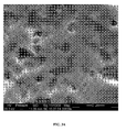
- FIGS. 4A and 4B Representative secondary electron micrographs, using a backscattered electron detector (sold under the trade mark Quanta 600F, operating in high vacuum at 20 kV, spot size 3, and work distance of 8 to 15 mm) of a control sample surface and a treated sample surface are presented in FIGS. 4A and 4B , respectively.
- Quanta 600F backscattered electron detector
- the R a of a number of the control samples and treated samples were measured using a contact profilometer (Zeiss Surfcom 5000 using a standard diamond stylus having a tip size of 1.5 to 2.0 ⁇ m.
- Four measurements were collected on the surface following long-axis at a rotation of 0 , 90 , 180 , 270 for each sample
- the sample length was 0.8 mm and the evaluation length was 0.8 mm ⁇ 5 (i.e., five sample lengths of 0.8 mm were used to evaluate a given R a value).
- Ten samples of each sample type (control and treated) were measured to determine an average R a value for the samples.
- the results of the R a measurements indicate that the control samples exhibit an average R a value of 0.40 ⁇ m ⁇ 0.06 ⁇ m , and the treated samples exhibit an average R a value of 0.38 ⁇ m ⁇ 0.05 ⁇ m. Accordingly, the treatment samples have statistically the same R a as the control samples.
- FIG. 5 Representative backscattered electron micrographs (Quanta 600F operating in high vacuum at 20 kV, spot size 3, and work distance of 8 to 15 mm) of the control and treated surfaces after testing are provided in FIGS. 6A and 6B , respectively.
- the residue of the polymethyl methacrylate cement appears as dark spots on the images in FIGS. 6A and 6B .
- the larger number of residues on the treated surface indicate generally greater adhesion of the cement with the substrate surface.
- Example 3 Alumina/glass blasted substrates - control and treated samples
- Cast cobalt-chromium-molybdenum (ASTM F75) rod stock having a diameter of 19 mm (0.75 inch) and a length of several metres are machine cut to cylinders having a diameter of 19 mm (0.75 inch) and a length of 38 mm (1.5 inch).
- the test surface was buffed (R a ⁇ 0.2 ⁇ m) before zirconia blasting to remove artifacts of machining.
- the test cylinders were particle blasted ("P-blasted") with a 50/50 mixture of 60 grit alumina particles/60 grit glass beads at typical room conditions using a work distance of about 4 to 8 inches at 138 kPa (20 psi) for a blasting time of about 5 to about 30 seconds.
- the blasted surfaces were blown clean with compressed air followed by ultrasonic cleaning in 1-2% detergent (Alconox) and reverse osmosis (“RO”) water. The surfaces were then dried at 60°C.
- FIGS. 7A and 7B Representative backscattered electron micrographs (Quanta 600F operating in high vacuum at 20 kV, spot size 3, and work distance of 8 to 15 mm) of a control sample surface and a treated sample surface are presented in FIGS. 7A and 7B , respectively.
- FIG. 7A provides indications of interstitial grit (dark spots) embedded in the sample surface.
- FIG. 7B shows that a substantial number of the embedded grit particles have been removed from the surface.
- the treated sample surface exhibits round surface pits, presumably formed during surface etching by the treatment formulation.
- the R a of a number of the control samples and treated samples were measured using a contact profilometer (Zeiss Surfcom 5000) utilizing a standard diamond stylus having a tip size of 1.5 to 2.0 ⁇ m.
- Four measurements were collected at 0 , 90 , 180 , 270 along the radial direction of the flat surface for each sample.
- the sample length was 0.8 mm and the evaluation length was 0.8 mm ⁇ 5 (i.e., five sample lengths of 0.8 mm were used to evaluate a given R a value).
- Three samples of each sample type were measured to determine an average R a value for the samples.
- DePuy SmartSet MV cement was moulded to each specimen in the fluid-form, having a cured-volume of 28.5 mm 3 and allowed to cure at ambient air for a minimum of 24 hours. The specimen was then inserted into pinned clevis fixtures attached to a MTS Alliance RF/100 static test frame where a static tensile load was applied to the specimen at 2.54 mm.min -1 until fracture.
- Tensile Strength (MPa) 16.7 ⁇ 1.0 22.7 ⁇ 1.9
- the treatment with the acid does not statistically affect the average R a value of the sample.
- the tensile strength of a cement bond formed with the treated sample shows an increase of almost 36%.
- the tensile fatigue strength of a cement bond formed with the control samples and the treated samples was determined using the following protocol.
- DePuy SmartSet MV was moulded to each specimen in the fluid-form, having a cured-volume of 28.5 mm 3 and allowed to cure at ambient air for a minimum of 24 hours.
- the specimen was then inserted into pinned clevis fixtures attached to a MTS servo-hydraulic test frame where a cyclic tensile load was applied at the specified stress-level at 2 Hz until fracture or until runout (i.e., a condition where a sample does not fail after being subjected to a predetermined number of cycles).
- a displacement limit of +2.54 mm was used to indicate failure.
- 8 specimens each were needed to produce 2 runouts at the maximum fatigue stress.
- FIG. 8 A graph depicting the results of the fatigue testing is shown in FIG. 8 .
- the presence of an arrow originating from a data point indicates that a runout condition, and the indicator "2 pass" indicates that two separate samples achieved the same runout condition.
- the results indicate that treated samples require a substantially higher tensile load and/or more cycles before fracturing occurs.
- Example 4 Comparison of R a , R q , R z , and R sk values in alumina/glass grit blasted samples
- R a , R q , R z , and R sk values were determined for each of the samples.
- the roughness values were all determined using a contact profilometer (Zeiss Surfcom 5000) utilizing a standard diamond stylus having a tip size of 1.5 to 2.0 ⁇ m.
- Four measurements were collected at 0 , 90 , 180 , 270 along the radial direction of the flat surface for each sample, and associated R a , R q , R z , and R sk values were calculated.
- the sample length was 0.8 mm and evaluation length was 0.8 mm ⁇ 5 (i.e., five sample lengths of 0.8 mm were used to evaluate a given R a value).
- Four samples of each sample type were each measured to determine an average R a , R q , R z , and R sk value for the samples.
- the averaged results are summarized in Table 3.
- Control Treated R a ( ⁇ m) 1.46 ⁇ 0.07 1.56 ⁇ 0.10
- R q ( ⁇ m) 1.92 ⁇ 0.11 2.02 ⁇ 0.10
- the difference in average values for R a , R q , and R z between the control and treated samples are not statistically different.
- the R sk value of the treated samples is more negative than the R sq value for the control samples, indicating that the treated sample surface exhibits negative draft and a less abrasive surface.
- R a and R sk values of the disks were measured using the contact profilometer after acid treatment. The average and the standard deviation of the R a and R sk values of the treated samples was calculated.
- Femoral knee implants (as sold under the trade mark Sigma by DePuy Orthopaedics Inc) were tested in accord with the following procedures.
- the implants were cast and grit-blasted.
- the blasted surfaces were blown clean with compressed air followed by ultrasonic cleaning in 1-2% detergent (Alconox) and reverse osmosis ("RO") water.
- the surfaces were then dried at 60°C.
- the remaining implant samples, designated treated samples were exposed to 8N HCl at room conditions (18 to 23 °C) for 24 hours.
- the treated implants were subsequently rinsed in RO water, ultrasonically cleaned in RO water for 20 minutes, then ultrasonically cleaned in RO water for 10 minutes and 5 minutes with interstitial rinsings in RO water.
- the cylinders are then dried at 60°C for at least 2 hours in an oven
- the acid treated samples were designated as treated samples.
- FIG. 9A provides a backscattered electron micrograph (Quanta 600F operating in high vacuum at 20 kV, spot size 3, and work distance of 8 to 15 mm) of a control implant surface.
- the dark spots in the micrograph provide indications of interstitial grit embedded in the sample surface.
- FIG. 9B provides a backscattered electron micrograph of a treated implant surface. As can be seen, a substantial number of the embedded grit particles have been removed from the surface, and round surface pits have been formed after treatment.
Applications Claiming Priority (1)
| Application Number | Priority Date | Filing Date | Title |
|---|---|---|---|
| US12/696,880 US8475536B2 (en) | 2010-01-29 | 2010-01-29 | Methods and devices for implants with improved cement adhesion |
Publications (2)
| Publication Number | Publication Date |
|---|---|
| EP2353548A2 true EP2353548A2 (de) | 2011-08-10 |
| EP2353548A3 EP2353548A3 (de) | 2011-10-19 |
Family
ID=43909881
Family Applications (1)
| Application Number | Title | Priority Date | Filing Date |
|---|---|---|---|
| EP11151450A Withdrawn EP2353548A3 (de) | 2010-01-29 | 2011-01-19 | Implantate mit verbesserter Zementhaftung |
Country Status (4)
| Country | Link |
|---|---|
| US (1) | US8475536B2 (de) |
| EP (1) | EP2353548A3 (de) |
| JP (1) | JP2011156360A (de) |
| CN (1) | CN102138835A (de) |
Families Citing this family (56)
| Publication number | Priority date | Publication date | Assignee | Title |
|---|---|---|---|---|
| US6610067B2 (en) | 2000-05-01 | 2003-08-26 | Arthrosurface, Incorporated | System and method for joint resurface repair |
| US6520964B2 (en) | 2000-05-01 | 2003-02-18 | Std Manufacturing, Inc. | System and method for joint resurface repair |
| US8177841B2 (en) | 2000-05-01 | 2012-05-15 | Arthrosurface Inc. | System and method for joint resurface repair |
| WO2010096826A1 (en) * | 2002-06-04 | 2010-08-26 | Arthrosurface Incorporated | Nanorough alloy substrate |
| US8388624B2 (en) | 2003-02-24 | 2013-03-05 | Arthrosurface Incorporated | Trochlear resurfacing system and method |
| EP1845890A4 (de) | 2003-11-20 | 2010-06-09 | Arthrosurface Inc | System und verfahren für rückläufigen vorgang |
| AU2005260590A1 (en) | 2004-06-28 | 2006-01-12 | Arthrosurface, Inc. | System for articular surface replacement |
| US7828853B2 (en) | 2004-11-22 | 2010-11-09 | Arthrosurface, Inc. | Articular surface implant and delivery system |
| US8758443B2 (en) | 2005-05-06 | 2014-06-24 | Titan Spine, Llc | Implants with integration surfaces having regular repeating surface patterns |
| US8992622B2 (en) | 2005-05-06 | 2015-03-31 | Titan Spine, Llc | Interbody spinal implant having a roughened surface topography |
| US8758442B2 (en) | 2005-05-06 | 2014-06-24 | Titan Spine, Llc | Composite implants having integration surfaces composed of a regular repeating pattern |
| US8262737B2 (en) | 2005-05-06 | 2012-09-11 | Titan Spine, Llc | Composite interbody spinal implant having openings of predetermined size and shape |
| US8814939B2 (en) | 2005-05-06 | 2014-08-26 | Titan Spine, Llc | Implants having three distinct surfaces |
| US8562685B2 (en) | 2005-05-06 | 2013-10-22 | Titan Spine, Llc | Spinal implant and integration plate for optimizing vertebral endplate contact load-bearing edges |
| US9168147B2 (en) | 2005-05-06 | 2015-10-27 | Titan Spine, Llc | Self-deploying locking screw retention device |
| US9125756B2 (en) | 2005-05-06 | 2015-09-08 | Titan Spine, Llc | Processes for producing regular repeating patterns on surfaces of interbody devices |
| US11096796B2 (en) | 2005-05-06 | 2021-08-24 | Titan Spine, Llc | Interbody spinal implant having a roughened surface topography on one or more internal surfaces |
| AU2007332787A1 (en) | 2006-12-11 | 2008-06-19 | Arthrosurface Incorporated | Retrograde resection apparatus and method |
| US20090035723A1 (en) * | 2007-08-03 | 2009-02-05 | Claus Daniel | Material with a repetitive pattern of micro-features for application in a living organism and method of fabrication |
| EP2262448A4 (de) | 2008-03-03 | 2014-03-26 | Arthrosurface Inc | System und verfahren zur wiederherstellung der knochenoberfläche |
| US8696759B2 (en) * | 2009-04-15 | 2014-04-15 | DePuy Synthes Products, LLC | Methods and devices for implants with calcium phosphate |
| US20100268227A1 (en) * | 2009-04-15 | 2010-10-21 | Depuy Products, Inc. | Methods and Devices for Bone Attachment |
| US10945743B2 (en) | 2009-04-17 | 2021-03-16 | Arthrosurface Incorporated | Glenoid repair system and methods of use thereof |
| US9662126B2 (en) | 2009-04-17 | 2017-05-30 | Arthrosurface Incorporated | Glenoid resurfacing system and method |
| BRPI1014961A2 (pt) | 2009-04-17 | 2016-04-26 | Arthrosurface Inc | "sistema e método para reparar um defeito em uma parte de uma superfície articular de um glenoídeo de paciente" |
| US8475536B2 (en) | 2010-01-29 | 2013-07-02 | DePuy Synthes Products, LLC | Methods and devices for implants with improved cement adhesion |
| AU2011222404A1 (en) | 2010-03-05 | 2012-09-27 | Arthrosurface Incorporated | Tibial resurfacing system and method |
| US9066716B2 (en) | 2011-03-30 | 2015-06-30 | Arthrosurface Incorporated | Suture coil and suture sheath for tissue repair |
| US8992619B2 (en) | 2011-11-01 | 2015-03-31 | Titan Spine, Llc | Microstructured implant surfaces |
| US20130165982A1 (en) | 2011-12-22 | 2013-06-27 | Arthrosurface Incorporated | System and Method for Bone Fixation |
| WO2013142480A1 (en) * | 2012-03-20 | 2013-09-26 | Titan Spine, Llc | Friction-fit spinal endplate and endplate-preserving method |
| DE112013003358T5 (de) | 2012-07-03 | 2015-03-19 | Arthrosurface, Inc. | System und Verfahren für Gelenkoberflächenersatz und -reparatur |
| EP2716261A1 (de) | 2012-10-02 | 2014-04-09 | Titan Spine, LLC | Implantate mit selbsteinsetzenden Ankern |
| US9498349B2 (en) | 2012-10-09 | 2016-11-22 | Titan Spine, Llc | Expandable spinal implant with expansion wedge and anchor |
| US9193033B2 (en) * | 2013-03-11 | 2015-11-24 | Howmedica Osteonics Corp. | Method of improving bond strength of polymeric implants with bone cement |
| US9492200B2 (en) | 2013-04-16 | 2016-11-15 | Arthrosurface Incorporated | Suture system and method |
| US20140343682A1 (en) * | 2013-05-17 | 2014-11-20 | Zimmer, Inc. | Convertible acetabular bearing |
| US9615935B2 (en) | 2014-01-30 | 2017-04-11 | Titan Spine, Llc | Thermally activated shape memory spring assemblies for implant expansion |
| JP6422938B2 (ja) * | 2014-02-21 | 2018-11-14 | 有限会社ITDN—Tokyo | インプラント体 |
| US10624748B2 (en) | 2014-03-07 | 2020-04-21 | Arthrosurface Incorporated | System and method for repairing articular surfaces |
| US11607319B2 (en) | 2014-03-07 | 2023-03-21 | Arthrosurface Incorporated | System and method for repairing articular surfaces |
| US9962265B2 (en) | 2014-03-07 | 2018-05-08 | Arthrosurface Incorporated | System and method for repairing articular surfaces |
| US10687956B2 (en) | 2014-06-17 | 2020-06-23 | Titan Spine, Inc. | Corpectomy implants with roughened bioactive lateral surfaces |
| TWI726940B (zh) | 2015-11-20 | 2021-05-11 | 美商泰坦脊柱股份有限公司 | 積層製造整形外科植入物之方法 |
| JP2019523092A (ja) | 2016-08-03 | 2019-08-22 | タイタン スパイン インコーポレイテッドTitan Spine,Inc. | αケースがなく、かつ骨誘導が増強されたチタンインプラント表面 |
| US10307260B2 (en) * | 2017-05-09 | 2019-06-04 | Depuy Ireland Unlimited Company | Tibial tray with fixation features |
| JP6893838B2 (ja) * | 2017-07-12 | 2021-06-23 | 日本ピストンリング株式会社 | インプラントの表面構造およびインプラントの表面構造の製造方法 |
| CA3108761A1 (en) | 2017-08-04 | 2019-02-07 | Arthrosurface Incorporated | Multicomponent articular surface implant |
| CN107607071B (zh) * | 2017-09-26 | 2020-11-06 | 深圳市领先医疗服务有限公司 | 可降解药物涂层支架涂层厚度的测量方法 |
| JP2020093352A (ja) * | 2018-12-13 | 2020-06-18 | 新東工業株式会社 | Co−Cr合金の表面改質方法、高疲労強度Co−Cr合金の製造方法、高疲労強度Co−Cr合金 |
| GB2609338B (en) | 2019-03-12 | 2023-06-14 | Arthrosurface Inc | Humeral and glenoid articular surface implant systems and methods |
| CN109968783A (zh) * | 2019-04-10 | 2019-07-05 | 深圳市贤俊龙彩印有限公司 | Pvc地板制作方法 |
| WO2021038562A1 (en) | 2019-08-26 | 2021-03-04 | Setbone Medical Ltd. | Implant comprising a plurality of hardening states |
| JP2021029831A (ja) * | 2019-08-28 | 2021-03-01 | 京セラ株式会社 | 生体用ジルコニアセラミック部材、及びその製造方法 |
| US11638776B1 (en) * | 2019-10-07 | 2023-05-02 | Smith & Nephew, Inc. | Medical devices and methods for forming medical devices having a porous structure |
| WO2023278386A1 (en) * | 2021-06-28 | 2023-01-05 | Exogenesis Corporation | Protection of orthopedic implants from wear |
Citations (3)
| Publication number | Priority date | Publication date | Assignee | Title |
|---|---|---|---|---|
| US7368065B2 (en) | 2005-06-23 | 2008-05-06 | Depuy Products, Inc. | Implants with textured surface and methods for producing the same |
| US20100268347A1 (en) | 2009-04-15 | 2010-10-21 | Weidong Tong | Micro and nano scale surface textured titanium-containing articles and methods of producing same |
| US20100268346A1 (en) | 2009-04-15 | 2010-10-21 | Weidong Tong | Nanotextured cobalt-chromium alloy articles having high wettability and method of producing same |
Family Cites Families (92)
| Publication number | Priority date | Publication date | Assignee | Title |
|---|---|---|---|---|
| CA962806A (en) | 1970-06-04 | 1975-02-18 | Ontario Research Foundation | Surgical prosthetic device |
| US3848272A (en) | 1972-01-13 | 1974-11-19 | United States Surgical Corp | Artificial hip joint |
| JPS5214095A (en) | 1975-07-23 | 1977-02-02 | Sumitomo Chemical Co | Implant in bone |
| GB1550010A (en) | 1976-12-15 | 1979-08-08 | Ontario Research Foundation | Surgical prosthetic device or implant having pure metal porous coating |
| US4156943A (en) | 1977-08-24 | 1979-06-05 | Collier John P | High-strength porous prosthetic device and process for making the same |
| DE2827529C2 (de) | 1978-06-23 | 1982-09-30 | Battelle-Institut E.V., 6000 Frankfurt | Implantierbarer Knochenersatzwerkstoff bestehend aus einem Metallkern und aus bioaktiven, gesinterten Calciumphosphat-Keramik-Partikeln und ein Verfahren zu seiner Herstellung |
| SE416175B (sv) | 1979-03-07 | 1980-12-08 | Per Ingvar Branemark | For implantering i kroppsvevnad serskilt benvevnad, avsett material |
| IE51564B1 (en) | 1980-03-27 | 1987-01-21 | Nat Res Dev | Antimicrobial surgical implants |
| JPS5911843A (ja) | 1982-07-12 | 1984-01-21 | 日本特殊陶業株式会社 | 義歯装着用歯科インプラント |
| US4475590A (en) * | 1982-12-13 | 1984-10-09 | The Standard Oil Company | Method for increasing oil recovery |
| DE3409372A1 (de) | 1984-03-14 | 1985-09-19 | Dr. Ruhland Nachf. GmbH, 8425 Neustadt | Material zum vitalisieren von implantatoberflaechen |
| US4612160A (en) | 1984-04-02 | 1986-09-16 | Dynamet, Inc. | Porous metal coating process and mold therefor |
| DE3414924A1 (de) | 1984-04-19 | 1985-10-31 | Klaus Dr.med. Dr.med.habil. 8000 München Draenert | Beschichtetes verankerungsteil fuer implantate |
| US5030233A (en) * | 1984-10-17 | 1991-07-09 | Paul Ducheyne | Porous flexible metal fiber material for surgical implantation |
| JPH0669482B2 (ja) | 1985-08-08 | 1994-09-07 | 住友化学工業株式会社 | 骨内インプラントの製造法 |
| US4780450A (en) | 1985-12-20 | 1988-10-25 | The University Of Maryland At Baltimore | Physically stable composition and method of use thereof for osseous repair |
| DD246028A1 (de) | 1986-02-12 | 1987-05-27 | Karl Marx Stadt Tech Hochschul | Keramisiertes metallimplantat |
| US4678523A (en) | 1986-07-03 | 1987-07-07 | Cabot Corporation | Corrosion- and wear-resistant duplex steel |
| FI80605C (fi) | 1986-11-03 | 1990-07-10 | Biocon Oy | Benkirurgisk biokompositmaterial. |
| CH674139A5 (de) | 1988-04-21 | 1990-05-15 | Sulzer Ag | |
| US5573771A (en) | 1988-08-19 | 1996-11-12 | Osteomedical Limited | Medicinal bone mineral products |
| US5258029A (en) | 1988-09-29 | 1993-11-02 | Collagen Corporation | Method for improving implant fixation |
| GB8824591D0 (en) | 1988-10-20 | 1988-11-23 | Royal Free Hosp School Med | Fractionation process |
| US5306500A (en) | 1988-11-21 | 1994-04-26 | Collagen Corporation | Method of augmenting tissue with collagen-polymer conjugates |
| US5171273A (en) | 1989-01-13 | 1992-12-15 | University Of Medicine And Dentistry Of New Jersey | Synthetic collagen orthopaedic structures such as grafts, tendons and other structures |
| US4990163A (en) | 1989-02-06 | 1991-02-05 | Trustees Of The University Of Pennsylvania | Method of depositing calcium phosphate cermamics for bone tissue calcification enhancement |
| JPH0629126B2 (ja) | 1989-03-29 | 1994-04-20 | 京都大学長 | 生体活性水酸アパタイト膜のコーティング法 |
| US5222987A (en) | 1989-04-12 | 1993-06-29 | Imperial Chemical Industries Plc | Composite material for use in a prosthetic device |
| US5141522A (en) | 1990-02-06 | 1992-08-25 | American Cyanamid Company | Composite material having absorbable and non-absorbable components for use with mammalian tissue |
| WO1991016012A1 (en) | 1990-04-20 | 1991-10-31 | Dynamet, Inc. | Porous metal surface and method of production |
| JPH07114812B2 (ja) | 1990-08-11 | 1995-12-13 | 株式会社日本健康増進研究会 | 光を利用した睡眠等の誘導補助具 |
| FR2666981B1 (fr) | 1990-09-21 | 1993-06-25 | Commarmond Jacques | Ligament synthetique vertebral. |
| SE468153B (sv) | 1990-10-08 | 1992-11-16 | Astra Meditec Ab | Saett foer ytbehandling av implantat av titan eller titanlegering |
| EP0560934B2 (de) | 1990-12-06 | 1999-11-10 | W.L. Gore & Associates, Inc. | Implantierbare bioresorbierbare artikel |
| US5205921A (en) | 1991-02-04 | 1993-04-27 | Queen's University At Kingston | Method for depositing bioactive coatings on conductive substrates |
| US5310539A (en) | 1991-04-15 | 1994-05-10 | Board Of Regents, The University Of Texas System | Melanin-based agents for image enhancement |
| US5157111A (en) | 1991-05-02 | 1992-10-20 | Pachence James M | Method of bonding collagen to fibers, particularly dacron |
| GB9122329D0 (en) | 1991-10-22 | 1991-12-04 | Isis Innovation | Bioactive material |
| US5478237A (en) | 1992-02-14 | 1995-12-26 | Nikon Corporation | Implant and method of making the same |
| US6066175A (en) | 1993-02-16 | 2000-05-23 | Henderson; Fraser C. | Fusion stabilization chamber |
| US5368881A (en) | 1993-06-10 | 1994-11-29 | Depuy, Inc. | Prosthesis with highly convoluted surface |
| US5607480A (en) | 1993-11-10 | 1997-03-04 | Implant Innovations, Inc. | Surgically implantable prosthetic devices |
| US6121172A (en) | 1993-11-15 | 2000-09-19 | The Trustees Of The University Of Pennsylvania | Composite materials using bone bioactive glass and ceramic fibers |
| US5681310A (en) | 1994-07-20 | 1997-10-28 | Yuan; Hansen A. | Vertebral auxiliary fixation device having holding capability |
| US5824093A (en) | 1994-10-17 | 1998-10-20 | Raymedica, Inc. | Prosthetic spinal disc nucleus |
| DE19504386C2 (de) | 1995-02-10 | 1997-08-28 | Univ Dresden Tech | Verfahren zur Herstellung einer gradierten Beschichtung aus Calciumphosphatphasen und Metalloxidphasen auf metallischen Implantaten |
| US7008634B2 (en) | 1995-03-03 | 2006-03-07 | Massachusetts Institute Of Technology | Cell growth substrates with tethered cell growth effector molecules |
| ES2185861T3 (es) | 1996-05-10 | 2003-05-01 | Isotis Nv | Material para implantes y procedimiento de fabricacion del mismo. |
| US6143948A (en) | 1996-05-10 | 2000-11-07 | Isotis B.V. | Device for incorporation and release of biologically active agents |
| US6066176A (en) | 1996-07-11 | 2000-05-23 | Oshida; Yoshiki | Orthopedic implant system |
| US5906234A (en) | 1996-10-22 | 1999-05-25 | Johnson & Johnson Professional, Inc. | Investment casting |
| US6162537A (en) | 1996-11-12 | 2000-12-19 | Solutia Inc. | Implantable fibers and medical articles |
| TW349224B (en) | 1997-05-15 | 1999-01-01 | Nat Science Council | Aluminum alloy electroplated with Co-Cr magnetic recording film thereon and process for producing the same |
| US6022376A (en) | 1997-06-06 | 2000-02-08 | Raymedica, Inc. | Percutaneous prosthetic spinal disc nucleus and method of manufacture |
| US6113640A (en) | 1997-06-11 | 2000-09-05 | Bionx Implants Oy | Reconstructive bioabsorbable joint prosthesis |
| GB9713330D0 (en) | 1997-06-25 | 1997-08-27 | Bridport Gundry Plc | Surgical implant |
| WO1999030632A1 (en) | 1997-12-18 | 1999-06-24 | Comfort Biomedical, Inc. | Bone augmentation for prosthetic implants and the like |
| US6139585A (en) | 1998-03-11 | 2000-10-31 | Depuy Orthopaedics, Inc. | Bioactive ceramic coating and method |
| US6179872B1 (en) | 1998-03-17 | 2001-01-30 | Tissue Engineering | Biopolymer matt for use in tissue repair and reconstruction |
| DE19811900C2 (de) | 1998-03-18 | 2003-12-11 | Kallies Feinchemie Ag | Biokompatibles Kompositmaterial, Verfahren zu seiner Herstellung und seine Verwendung |
| DE19812713A1 (de) | 1998-03-24 | 1999-09-30 | Merck Patent Gmbh | Verfahren zur Herstellung von mineralisierten Kollagenfibrillen und deren Verwendung als Knochenersatzwerkstoff |
| DE19812714A1 (de) | 1998-03-24 | 1999-09-30 | Merck Patent Gmbh | Verfahren zur Herstellung von mineralisierten Kollagenfibrillen und deren Verwendung als Knochenersatzwerkstoff |
| DE10029520A1 (de) | 2000-06-21 | 2002-01-17 | Merck Patent Gmbh | Beschichtung für metallische Implantatmaterialien |
| CH694935A5 (de) | 2000-07-26 | 2005-09-30 | Straumann Holding Ag | Oberflaechenmodifizierte Implantate. |
| IL149700A0 (en) | 2000-09-19 | 2002-11-10 | Eduardo Anitua Aldecoa | Method for surface treatment of implants or prosthesis made of titanium or other materials |
| US6827743B2 (en) | 2001-02-28 | 2004-12-07 | Sdgi Holdings, Inc. | Woven orthopedic implants |
| AU2002360511B2 (en) | 2001-12-06 | 2008-08-28 | Smith & Nephew, Inc. | In-situ oxidized textured surfaces for prosthetic devices and method of making same |
| SE523288C2 (sv) | 2002-07-19 | 2004-04-06 | Astra Tech Ab | Ett implantat och ett förfarande för behandling av en implantatyta |
| EP1542626B1 (de) | 2002-08-15 | 2012-09-26 | Synthes GmbH | Geführtes künstliches bandscheibenimplantat |
| US20040167632A1 (en) * | 2003-02-24 | 2004-08-26 | Depuy Products, Inc. | Metallic implants having roughened surfaces and methods for producing the same |
| ATE395092T1 (de) | 2003-07-08 | 2008-05-15 | Poligrat Gmbh | Zementierbare endoprothesen |
| US20070160622A1 (en) | 2005-12-07 | 2007-07-12 | Medivas, Llc | Method for assembling a polymer-biologic delivery composition |
| ATE446722T1 (de) * | 2003-11-04 | 2009-11-15 | Friadent Gmbh | Dentalimplantatelement |
| US20050171604A1 (en) | 2004-01-20 | 2005-08-04 | Alexander Michalow | Unicondylar knee implant |
| US20060018859A1 (en) | 2004-07-16 | 2006-01-26 | Carter Daniel C | Modified human serum albumin with reduced or eliminated affinity to chemical or biological contaminants at Cys 34 |
| US8329202B2 (en) | 2004-11-12 | 2012-12-11 | Depuy Products, Inc. | System and method for attaching soft tissue to an implant |
| DE602004008313T2 (de) | 2004-12-23 | 2008-05-08 | Plus Orthopedics Ag | Verfahren zum Oberfläche-Fertigbearbeiten von Knochenimplantaten |
| US7901462B2 (en) | 2005-06-23 | 2011-03-08 | Depuy Products, Inc. | Implants with textured surface and methods for producing the same |
| JP5100023B2 (ja) | 2006-03-29 | 2012-12-19 | 京セラメディカル株式会社 | 生体材料、及びそれを用いた人工関節並びにその製造方法 |
| US20070260324A1 (en) | 2006-05-05 | 2007-11-08 | Joshi Ashok V | Fully or Partially Bioresorbable Orthopedic Implant |
| US8524265B2 (en) | 2006-08-17 | 2013-09-03 | Warsaw Orthopedic, Inc. | Medical implant sheets useful for tissue regeneration |
| US7892071B2 (en) * | 2006-09-29 | 2011-02-22 | Depuy Products, Inc. | Orthopaedic component manufacturing method and equipment |
| US8334044B2 (en) * | 2007-02-06 | 2012-12-18 | The Board Of Trustees Of The Leland Stanford Junior University | Hydrogel-metal assembly |
| US20090005868A1 (en) | 2007-06-27 | 2009-01-01 | Depuy Products, Inc. | Osteogenic prosthesis, associated instrument, and associated method |
| US20090008365A1 (en) | 2007-07-06 | 2009-01-08 | Depuy Products, Inc. | Microtextured Implants and Methods of Making Same |
| DE602008002889D1 (de) | 2007-08-20 | 2010-11-18 | Depuy Products Inc | Ultrapassivierung von Chromlegierungen |
| JP5248848B2 (ja) | 2007-12-11 | 2013-07-31 | 山八歯材工業株式会社 | インプラントの製造方法及び人工歯根の製造方法 |
| US20090204213A1 (en) | 2008-02-13 | 2009-08-13 | Depuy Products, Inc. | Metallic implants |
| US20090266791A1 (en) | 2008-04-28 | 2009-10-29 | Depuy Products, Inc. | Implant surfaces and treatments for wear reduction |
| US8696759B2 (en) | 2009-04-15 | 2014-04-15 | DePuy Synthes Products, LLC | Methods and devices for implants with calcium phosphate |
| US20100268227A1 (en) | 2009-04-15 | 2010-10-21 | Depuy Products, Inc. | Methods and Devices for Bone Attachment |
| US8475536B2 (en) | 2010-01-29 | 2013-07-02 | DePuy Synthes Products, LLC | Methods and devices for implants with improved cement adhesion |
-
2010
- 2010-01-29 US US12/696,880 patent/US8475536B2/en active Active
-
2011
- 2011-01-19 EP EP11151450A patent/EP2353548A3/de not_active Withdrawn
- 2011-01-28 JP JP2011016302A patent/JP2011156360A/ja active Pending
- 2011-01-28 CN CN2011100372674A patent/CN102138835A/zh active Pending
Patent Citations (3)
| Publication number | Priority date | Publication date | Assignee | Title |
|---|---|---|---|---|
| US7368065B2 (en) | 2005-06-23 | 2008-05-06 | Depuy Products, Inc. | Implants with textured surface and methods for producing the same |
| US20100268347A1 (en) | 2009-04-15 | 2010-10-21 | Weidong Tong | Micro and nano scale surface textured titanium-containing articles and methods of producing same |
| US20100268346A1 (en) | 2009-04-15 | 2010-10-21 | Weidong Tong | Nanotextured cobalt-chromium alloy articles having high wettability and method of producing same |
Also Published As
| Publication number | Publication date |
|---|---|
| JP2011156360A (ja) | 2011-08-18 |
| CN102138835A (zh) | 2011-08-03 |
| EP2353548A3 (de) | 2011-10-19 |
| US20110190902A1 (en) | 2011-08-04 |
| US8475536B2 (en) | 2013-07-02 |
Similar Documents
| Publication | Publication Date | Title |
|---|---|---|
| EP2353548A2 (de) | Implantate mit verbesserter Zementhaftung | |
| Sinnett-Jones et al. | Micro-abrasion–corrosion of a CoCrMo alloy in simulated artificial hip joint environments | |
| Sampaio et al. | Tribocorrosion behavior of veneering biomedical PEEK to Ti6Al4V structures | |
| US6539607B1 (en) | Enhanced biocompatible implants and alloys | |
| Arola et al. | Abrasive waterjet peening: a new method of surface preparation for metal orthopedic implants | |
| Beake et al. | Comparison of nano-fretting and nano-scratch tests on biomedical materials | |
| US20070032877A1 (en) | Coated ceramic total joint arthroplasty and method of making same | |
| Tritschler et al. | Fretting corrosion of materials for orthopaedic implants: a study of a metal/polymer contact in an artificial physiological medium | |
| Choudhury et al. | Fabrication and characterization of DLC coated microdimples on hip prosthesis heads | |
| Oskouei et al. | A new finding on the in-vivo crevice corrosion damage in a CoCrMo hip implant | |
| Faria et al. | Laser-assisted production of HAp-coated zirconia structured surfaces for biomedical applications | |
| EP1715814A1 (de) | Medizinprodukt mit glatter gehärteter oberfläche | |
| Liu et al. | Single asperity sub-nano to nanoscale wear and tribocorrosion of wrought CoCrMo and additively manufactured CoCrMoW alloys | |
| Mitchell et al. | Onset of nanoscale wear of metallic implant materials: Influence of surface residual stresses and contact loads | |
| Yetik et al. | The effects of grit size and blasting pressure on the surface properties of grit blasted Ti6Al4V alloy | |
| Namus et al. | Correlation of the wear transition in CoCrMo alloys with the formation of a nanocrystalline surface layer and a proteinaceous surface film | |
| Bryant et al. | The role of surface pre-treatment on the microstructure, corrosion and fretting corrosion of cemented femoral stems | |
| Ryu et al. | Mechanical load assisted dissolution response of biomedical cobalt–chromium and titanium metallic alloys: influence of in-plane stress and chemical environment | |
| Xie et al. | Application of the Taguchi method to areal roughness-based surface topography control by waterjet treatments | |
| Chrzanowski et al. | Chemical, corrosion and topographical analysis of stainless steel implants after different implantation periods | |
| Mathew et al. | Tribocorrosion in hip modular taper junctions: Load-triggered transitions in electrochemical and mechanical behavior | |
| Sonekar et al. | High End Corrosion and Wear Behavior of HA-CNT Coatings on Biomaterials | |
| Mazzonello | Duplex surface engineered CoCrMo orthopaedic alloy using commercial treatments: a corrosion-wear investigation | |
| Hamtaiepour et al. | Evaluating the effect of pretreatment parameters on Co-Cr-Mo alloy prior to physical vapor deposition coating | |
| Ahmed | Coating and surface treatment for novel biomedical implants and their corrosion resistance |
Legal Events
| Date | Code | Title | Description |
|---|---|---|---|
| PUAI | Public reference made under article 153(3) epc to a published international application that has entered the european phase |
Free format text: ORIGINAL CODE: 0009012 |
|
| AK | Designated contracting states |
Kind code of ref document: A2 Designated state(s): AL AT BE BG CH CY CZ DE DK EE ES FI FR GB GR HR HU IE IS IT LI LT LU LV MC MK MT NL NO PL PT RO RS SE SI SK SM TR |
|
| AX | Request for extension of the european patent |
Extension state: BA ME |
|
| PUAL | Search report despatched |
Free format text: ORIGINAL CODE: 0009013 |
|
| AK | Designated contracting states |
Kind code of ref document: A3 Designated state(s): AL AT BE BG CH CY CZ DE DK EE ES FI FR GB GR HR HU IE IS IT LI LT LU LV MC MK MT NL NO PL PT RO RS SE SI SK SM TR |
|
| AX | Request for extension of the european patent |
Extension state: BA ME |
|
| RIC1 | Information provided on ipc code assigned before grant |
Ipc: A61F 2/30 20060101AFI20110914BHEP |
|
| 17P | Request for examination filed |
Effective date: 20120417 |
|
| STAA | Information on the status of an ep patent application or granted ep patent |
Free format text: STATUS: THE APPLICATION IS DEEMED TO BE WITHDRAWN |
|
| 18D | Application deemed to be withdrawn |
Effective date: 20120420 |