EP2352573B1 - Zentrifugalabscheider - Google Patents
Zentrifugalabscheider Download PDFInfo
- Publication number
- EP2352573B1 EP2352573B1 EP09764178.1A EP09764178A EP2352573B1 EP 2352573 B1 EP2352573 B1 EP 2352573B1 EP 09764178 A EP09764178 A EP 09764178A EP 2352573 B1 EP2352573 B1 EP 2352573B1
- Authority
- EP
- European Patent Office
- Prior art keywords
- electric motor
- centrifugal precipitator
- centrifugal
- precipitator according
- internal combustion
- Prior art date
- Legal status (The legal status is an assumption and is not a legal conclusion. Google has not performed a legal analysis and makes no representation as to the accuracy of the status listed.)
- Revoked
Links
Images



Classifications
-
- B—PERFORMING OPERATIONS; TRANSPORTING
- B04—CENTRIFUGAL APPARATUS OR MACHINES FOR CARRYING-OUT PHYSICAL OR CHEMICAL PROCESSES
- B04B—CENTRIFUGES
- B04B9/00—Drives specially designed for centrifuges; Arrangement or disposition of transmission gearing; Suspending or balancing rotary bowls
- B04B9/02—Electric motor drives
- B04B9/04—Direct drive
-
- B—PERFORMING OPERATIONS; TRANSPORTING
- B01—PHYSICAL OR CHEMICAL PROCESSES OR APPARATUS IN GENERAL
- B01D—SEPARATION
- B01D45/00—Separating dispersed particles from gases or vapours by gravity, inertia, or centrifugal forces
- B01D45/12—Separating dispersed particles from gases or vapours by gravity, inertia, or centrifugal forces by centrifugal forces
- B01D45/14—Separating dispersed particles from gases or vapours by gravity, inertia, or centrifugal forces by centrifugal forces generated by rotating vanes, discs, drums or brushes
-
- B—PERFORMING OPERATIONS; TRANSPORTING
- B04—CENTRIFUGAL APPARATUS OR MACHINES FOR CARRYING-OUT PHYSICAL OR CHEMICAL PROCESSES
- B04B—CENTRIFUGES
- B04B15/00—Other accessories for centrifuges
- B04B15/02—Other accessories for centrifuges for cooling, heating, or heat insulating
-
- B—PERFORMING OPERATIONS; TRANSPORTING
- B04—CENTRIFUGAL APPARATUS OR MACHINES FOR CARRYING-OUT PHYSICAL OR CHEMICAL PROCESSES
- B04B—CENTRIFUGES
- B04B5/00—Other centrifuges
- B04B5/005—Centrifugal separators or filters for fluid circulation systems, e.g. for lubricant oil circulation systems
-
- B—PERFORMING OPERATIONS; TRANSPORTING
- B04—CENTRIFUGAL APPARATUS OR MACHINES FOR CARRYING-OUT PHYSICAL OR CHEMICAL PROCESSES
- B04B—CENTRIFUGES
- B04B5/00—Other centrifuges
- B04B5/12—Centrifuges in which rotors other than bowls generate centrifugal effects in stationary containers
-
- B—PERFORMING OPERATIONS; TRANSPORTING
- B04—CENTRIFUGAL APPARATUS OR MACHINES FOR CARRYING-OUT PHYSICAL OR CHEMICAL PROCESSES
- B04B—CENTRIFUGES
- B04B7/00—Elements of centrifuges
- B04B7/02—Casings; Lids
-
- F—MECHANICAL ENGINEERING; LIGHTING; HEATING; WEAPONS; BLASTING
- F01—MACHINES OR ENGINES IN GENERAL; ENGINE PLANTS IN GENERAL; STEAM ENGINES
- F01M—LUBRICATING OF MACHINES OR ENGINES IN GENERAL; LUBRICATING INTERNAL COMBUSTION ENGINES; CRANKCASE VENTILATING
- F01M11/00—Component parts, details or accessories, not provided for in, or of interest apart from, groups F01M1/00 - F01M9/00
- F01M11/10—Indicating devices; Other safety devices
-
- F—MECHANICAL ENGINEERING; LIGHTING; HEATING; WEAPONS; BLASTING
- F01—MACHINES OR ENGINES IN GENERAL; ENGINE PLANTS IN GENERAL; STEAM ENGINES
- F01M—LUBRICATING OF MACHINES OR ENGINES IN GENERAL; LUBRICATING INTERNAL COMBUSTION ENGINES; CRANKCASE VENTILATING
- F01M13/00—Crankcase ventilating or breathing
-
- B—PERFORMING OPERATIONS; TRANSPORTING
- B04—CENTRIFUGAL APPARATUS OR MACHINES FOR CARRYING-OUT PHYSICAL OR CHEMICAL PROCESSES
- B04B—CENTRIFUGES
- B04B5/00—Other centrifuges
- B04B5/12—Centrifuges in which rotors other than bowls generate centrifugal effects in stationary containers
- B04B2005/125—Centrifuges in which rotors other than bowls generate centrifugal effects in stationary containers the rotors comprising separating walls
-
- F—MECHANICAL ENGINEERING; LIGHTING; HEATING; WEAPONS; BLASTING
- F01—MACHINES OR ENGINES IN GENERAL; ENGINE PLANTS IN GENERAL; STEAM ENGINES
- F01M—LUBRICATING OF MACHINES OR ENGINES IN GENERAL; LUBRICATING INTERNAL COMBUSTION ENGINES; CRANKCASE VENTILATING
- F01M13/00—Crankcase ventilating or breathing
- F01M13/04—Crankcase ventilating or breathing having means for purifying air before leaving crankcase, e.g. removing oil
- F01M2013/0422—Separating oil and gas with a centrifuge device
Definitions
- the invention relates to centrifugal separator for separating oil mist from the crankcase ventilation gas of an internal combustion engine or for separating solid impurities from the lubricating oil of an internal combustion engine, wherein the centrifugal separator having a rotatably driven rotor, a rotor accommodating housing and a rotary drive for the rotor, wherein the rotary drive by a Electric motor is formed, which is arranged in the housing and wherein the Zentrifugalabscheider have means for cooling the electric motor.
- Centrifugal separator with the features specified above are from the document WO 01/03846 A1 known. From this document also shows a centrifugal separator, wherein at least one heat sink is provided for cooling the electric motor.
- a support body is provided here according to FIG 21, which carries on its upper side a board of an electronic control unit. With a radially inwardly projecting projection of the support body rests against the outer circumference of the stator of the electric motor. About a relatively thin, the circuit board outside surrounding wall of the support body is connected to a top of this wall mounted heat sink in combination. On the inside of this wall also other components are attached, which are not specifically described, but recognizable power transistors that also emit heat during operation.
- this known centrifugal separator is limited in its use to the separation of solid particles from a liquid, specifically from the lubricating oil of an internal combustion engine. Therefore, in the known centrifugal separator also does not occur the problem that settle from an inflowing gas to be purified already in front of the rotor in an inlet of the separator liquid portions.
- centrifugal separator serves for the separation of solid and / or liquid particles from a gas stream.
- the separator has a rotor which is formed by a stack of plates and which is arranged in a housing and can be set in rotation by means of an electric motor likewise arranged in the housing.
- the gas stream to be cleaned enters the housing axially and flows through the rotor in the direction from radially inward to radially outward.
- the deposited particles strike the inner surface of a peripheral wall of the housing of the centrifugal separator and are discharged from there by gravity down into a separate outlet.
- the cleaned gas flows in the axial direction upwards to a clean gas outlet provided there.
- the electric motor for driving the rotor.
- centrifugal separators of the type described above In practice, it has proved in centrifugal separators of the type described above as a problem that the electric motor for driving the rotor to overheat and thereby damage, affecting the reliability of such a centrifugal separator.
- the object is to provide centrifugal separator of the type mentioned, which ensure a reliable long-term operation, on the one hand in particular a low-resistance, effective heat dissipation from the electric motor should be achieved.
- the solution of this object succeeds according to the invention with a centrifugal separator of the type mentioned, in which at least one heat sink is provided as a means for cooling the electric motor and thereby is characterized in that the heat sink is connected to a stator of the electric motor or this forms.
- the means for cooling the electric motor ensures that the electric motor in the housing of the centrifugal separator is always sufficiently cooled, so that overheating and damage caused by the electric motor can be avoided. As a result, the electric motor reaches a sufficient for the operating time of the centrifugal separator life, so that premature failure of the electric motor is no longer to be feared.
- the means for cooling allow to use an electric motor with high specific power, which allows a small size of the electric motor for driving the rotor. Because the heat sink is connected to or forms the stator of the electric motor, the heat generated in the electric motor can be dissipated in as little resistance as possible.
- the heat sink is used in particular to provide an enlarged area over which the electric motor can deliver the heat generated in it.
- a heat sink provides its own heat capacity absorption of heat from the electric motor to dissipate heat from the electric motor before its temperature reaches a harmful level.
- the cooling body during operation of the centrifugal separator of the crankcase ventilation gas or the coolant or the lubricating oil or the fuel or cooling air of the internal combustion engine or ambient air can be overflowed and / or flowed through.
- the heat sink in turn is actively cooled, which further increases the cooling effect of the heat sink for the electric motor.
- the heat sink preferably has a plurality of wings.
- the wings offer a large area over which heat can be dissipated, for example to the centrifugal separator flowing through, to be cleaned medium.
- the heat sink is rotationally symmetrical and that the wings are radially aligned and distributed over the circumference of the heat sink.
- the heat sink is preferably a one-piece metal part, preferably a die-cast part made of light metal, in particular aluminum or magnesium.
- the housing is preferably a one-piece plastic part, preferably an injection molded part made of a thermoplastic, in particular polyamide.
- the electric motor is preferably arranged on an upper side of the centrifugal separator which is accessible from the outside and in the mounted state outside the associated internal combustion engine.
- the heat sink is designed as a lid forming the top of the centrifugal separator.
- the heat sink is thus outside of the internal combustion engine and can there, for example. be effectively cooled by wind or ventilated cooling air.
- the lid receives or contains an electronic unit belonging to the electric motor.
- heat loss of the electronics unit can also be delivered through the lid.
- the lid is divided into two thermally separated lid parts and that a first cover part in heat-conducting connection with the electric motor and a second cover part is in heat-conducting connection with the electronics unit.
- thermo separation can be achieved in that the electric motor and the electronics unit are separated from each other by a thermal insulation element.
- an attachment with a respective inlet and outlet for a cooling liquid flowing over the cover can be connected or connected to the cover.
- An embodiment of the invention provides that the housing has a lower part with an inlet for the rotor to be supplied raw medium and an outlet for separated from the raw medium, the lower part produced as a separate item and relative to the rest of the housing with this in different Vercardhrenen connectable , preferably weldable or joinable, is.
- the housing is designed without lower part and can be inserted or screwed under sealing by seals in a module base, in particular an oil filter module, or in a cylinder head cover of the internal combustion engine.
- the centrifugal separator can also be designed as an independent auxiliary unit of an internal combustion engine and be connectable to the internal combustion engine.
- the Zentrifugalabscheider is suitably equipped with a connection flange, with which it can be flanged to a module base, in particular an oil filter module, or to a cylinder head cover of the internal combustion engine, which run through the flange part or all of the required flow connections from and to the internal combustion engine.
- the centrifugal separator can be connected by means of the connecting flange with a functional module of the internal combustion engine, in which case the functional module can be connected to the internal combustion engine.
- FIG. 1 shows a first centrifugal separator 1 in side view, wherein a housing 10 of the separator 1 is visible, which comprises a substantially cylindrical lower part 11 and a likewise cylindrical in its basic form, in the upper part frustoconical cover 12.
- the underside of the lower part 11 forms a connecting flange 18, with which the centrifugal separator 1 with an associated internal combustion engine, which is not shown here, or with a belonging to the internal combustion engine function module is connectable.
- FIG. 2 shows the centrifugal separator 1 from FIG. 1 in a bottom view.
- Radial outside is located on the now visible side of the housing 10 of the connecting flange 18, in the course in FIG. 2 on the left an outlet 15 for in the centrifugal separator 1 separated medium, for example, lubricating oil from the crankcase ventilation gas of an internal combustion engine, is visible.
- Radially inwardly offset from the outlet 15 is an inlet 13 for the raw medium to be cleaned in the centrifugal separator 1, for example the crankcase ventilation gas of the associated internal combustion engine.
- the inlet 13 for the raw medium is in fluid communication with the crankcase of the internal combustion engine; the outlet 15 then communicates, for example, with an oil sump of the internal combustion engine.
- the internal structure of the centrifugal separator 1 becomes clear.
- a rotor 2 is rotatably mounted on an axle 4 by means of two bearings 51, 52.
- the rotor 2 in this case comprises a separator part 20 and a carrier part 21.
- the separator part 20 consists of a plate stack 26 per se known embodiment, wherein the stack of plates 26 rests on a plate support 25 and is covered at the top by a cover plate 27.
- the arrangement of plate support 25, plate stack 26 and top plate 27 is compressed by a coil spring 28, so that the arrangement mutually assumes a stable position.
- the support member 21 has an upwardly projecting sleeve-shaped portion 24 ', on which the Abscheiderteil 20 is plugged from above and secured against rotation.
- an electric motor 3 which is arranged below the rotor 2, is used here.
- the electric motor 3 has a stator 32 surrounding the lower portion 42 of the axle 4, for example an electromagnetic coil arrangement.
- Around the stand 32 around a rotor 31 is arranged, which is formed for example by a magnetic sleeve.
- the rotor 31 is rotationally connected to a sleeve-shaped portion 24 of the support part 21 of the rotor 2.
- the carrier part 21 of the rotor 2 is formed here simultaneously as a heat sink 30 for the electric motor 3.
- the support member 21 has this in addition to the standing in direct heat-conductive contact with the electric motor 3 sleeve-shaped portion 24 a plurality of circumferentially spaced wings 22, which increase the surface of the support member 21 and thus form an effective heat sink 30.
- the heat sink 30 is overflowed by the medium to be cleaned through which the centrifugal separator 1 flows, whereby the heat released by the electric motor 3 is removed therefrom and transferred to the medium flowing through the centrifugal separator 1.
- the axis 4 is fixed in position with its lower end 41 with the lower part 11 of the housing 10.
- the upper end 43 of the axle 4 is centered in a centering receptacle 17 on the underside of the lid 12.
- a game in the longitudinal direction between the bearings 51, 52 is compensated, in which case the one bearing 51 is a movable bearing and the other bearing 52 is a fixed bearing.
- the lower bearing 51 is arranged by a below, connected to the axis 4 Circlip 53 limited in its mobility to axially below.
- a securing sleeve 54 is mounted on the upper portion 43 of the axle 4.
- the centrifugal separator 1 For supplying the medium to be cleaned in the centrifugal separator 1, such as crankcase ventilation gas, the serves in FIG. 4 visible inlet 13 in the upper region of the lower part 11, through which the medium enters the interior of the lid 12 to the underside of the rotor 2.
- the medium to be cleaned flows in a known manner in the rotor in the axial direction upward and is distributed to the spaces between the plates of the plate stack 26.
- the rotating separator part 20 the medium to be cleaned in the radial direction passes to the outside, thereby resulting by centrifugal forces liquid and / or solid particles are removed from the medium.
- the purified medium then flows radially outward from the rotor 2 upwards and leaves the centrifugal separator 1 through the in FIG.
- FIG. 5 shows a second centrifugal separator 1 in side view.
- the centrifugal separator 1 essentially corresponds to the example according to FIG. 1 , Different is in the separator 1 after FIG. 5 in that a separate coolant through the centrifugal separator 1 can be guided here.
- a coolant passage 61 is formed in the lower part 11 according to FIG. 5 on the right side.
- This port 61 is connected to a in FIG. 5 invisible, in the interior of the centrifugal separator 1 extending coolant channel in conjunction.
- the other end of the coolant channel opens into a second coolant channel connection 62, which is formed here centrally on the upper side of the lid 12.
- a separate coolant can be supplied and discharged via the connections 61 and 62 by means of lines, not shown, for example cooling water or lubricating oil or fuel of the associated internal combustion engine.
- the connecting flange 18 is again provided.
- FIG. 6 shown bottom view of the centrifugal 1 from FIG. 5
- the arrangement of the raw material inlet 13 and the separated medium outlet 15 becomes visible.
- the course of a section of the coolant channel 6 is visible, which serves for active cooling of the electric motor of the centrifugal separator 1, as shown in FIGS FIGS. 7 and 8 becomes clearer.
- FIGS. 7 and 8 show the centrifugal from the FIGS. 5 and 6 in two longitudinal sections.
- the rotor 2 inside the housing 10 corresponds to that of the centrifugal separator 1 according to the FIGS. 1 to 4 ; their description will refer to this.
- the coolant channel 6 begins at the coolant channel port 61 radially outward on the lower part 11 of the housing 10 and runs from there first radially inwardly to the center of the lower part 11. There, the coolant channel 6 meets the axis 4, which is designed here as a hollow shaft, so that the coolant channel 6 extends in its further course in the axial direction upwards through the axis 4. In the center of the lid 12 is the second coolant channel connection 62, through which the coolant can be removed.
- the direction of flow of the coolant in the coolant channel 6 can also be reversed.
- FIG. 9 a third embodiment of the centrifugal separator 1 is shown in side view.
- the basic form of the centrifugal separator 1 according to FIG. 9 again corresponds to that of the embodiments of the FIGS. 1 and 5 ,
- FIG. 12 shows the arrangement of the raw material inlet 13 and the separated medium outlet 15 in the separator 1 according to FIG. 9 , Furthermore, in FIG. 10 the course of the coolant channel 6 with the central cooling zone 60 seen here in the radial direction can be seen.
- the underside of the housing 10 again forms the connecting flange 18 for connecting the centrifugal separator 1 with an associated internal combustion engine or a functional module of the internal combustion engine.
- the two longitudinal sections according to the section lines AA and BB in FIG. 10 are in the FIGS. 11 and 12 shown.
- the rotor 2 of the centrifugal separator 1 is also executed in this third embodiment coincident with the rotors 2 of the two embodiments described above; Reference is made to the preceding description.
- FIG. 11 the inlet 13 for supplying the raw medium to be cleaned to the rotor 2 is visible. Radially outward in the lower part 11, the outlet 15 for the separated medium is visible. The underside of the lower part 11 again forms the connecting flange 18.
- FIG. 12 shows the course of the coolant channel 6 through the lower part 11 of the housing 10.
- the coolant channel connection 61 for supplying the coolant. From there, the coolant channel 6 leads in the radial direction inwards, where it opens into an annular cooling zone 60.
- the second coolant channel connection 62 On the opposite side of the lower part 11, there is the second coolant channel connection 62, which is connected to a second section of the coolant channel 6 that extends radially outward from the cooling zone 60 and serves to discharge the coolant.
- the annular cooling zone 60 of the coolant channel 6 extends below the electric motor 3 and the cooling medium can thus absorb and dissipate heat from the electric motor 3 effectively. To avoid damage to the electric motor by the cooling medium a corresponding seal is provided here, of course.
- centrifugal separator 1 corresponds to the previously described embodiments, to the description of which reference is made.
- FIG. 13 shows a further centrifugal separator 1, here in a perspective view, which is provided for the de-oiling of crankcase ventilation gas of an internal combustion engine. It is a housing 10 of the separator 1 visible from the outside, which has a substantially cylindrical shape. Down the housing 10 is closed by a lower part 11. On the top side sits on the housing 10, a lid 12. At the in FIG. 13 to the right rear side facing the housing 10, a connecting flange 18 is formed, with which the centrifugal separator 1 with an associated internal combustion engine or with a belonging to the internal combustion engine function module, which are not shown here, is connectable.
- an inlet 13 is formed for the raw medium, wherein the inlet 13 is formed here as a radially extending hose connection piece.
- an outlet 15 for separated medium is provided on the lower part 11, wherein the outlet 15 is likewise designed here as a hose connecting piece.
- a pressure control valve 8 is arranged, through which the gas purified in the separator flows to the outlet 14 for the clean medium. Also, the outlet 14 is designed as a hose connection piece. The pressure control valve 8 serves to regulate the pressure in the crankcase of the associated internal combustion engine.
- the lid 12 is formed here as a cooling lid 30 'and has for this purpose at its periphery a number of cooling fins or wings.
- the cooling lid 30 ' is divided into two thermally separated lid parts 30.1' and 30.2 '.
- the one cover part 30.1 ' is heat-conducting with a arranged in the upper region of the interior of the housing 10, not visible here electric motor heat sink or other heat-emitting part of an electric motor.
- the other cover part 30.2 ' is thermally conductively connected to a likewise arranged in the upper region of the interior of the housing 10, not visible here electronic unit of the electric motor.
- the electric motor and its electronics unit are largely cooled without mutual interference.
- an electrical connection 16 is provided in the upper side of the cover 12 or 30 ', for example a socket for a power supply cable of the electric motor.
- the centrifugal separator 1 On the basis of in the Figures 14 and 15 shown longitudinal sections of the centrifugal separator 1 according to FIG. 13 its internal structure becomes recognizable.
- a rotor 2 Inside the housing 10, a rotor 2 with an axis 4 by means of two bearings 51, 52 is rotatably mounted.
- the rotor 2 comprises a separator part 20 and a carrier part 21.
- the separator part 20 consists of a plate stack 26 of a known type, the plate stack 26 resting on a plate support 25 and being covered at the top by a cover plate 27.
- the arrangement of plate support 25, plate stack 26 and top plate 27 is compressed from below by a coil spring 28, so that the arrangement mutually assumes a stable position.
- an electric motor 3 which is arranged above the rotor 2, is used here.
- the electric motor 3 has a stator 32 surrounding the upper portion 43 of the axle 4, for example an electromagnetic coil arrangement.
- Around the stand 32 around a rotor 31 is arranged, which is formed for example by a magnetic sleeve.
- the rotor 31 is here rotationally connected to the upper portion 43 of the shaft 4.
- the stator 32 of the motor 3 is here designed with a heat sink 30 for the electric motor 3.
- the heat sink 30 is in heat-conducting contact with the cover part 30.1 'or is integrally formed therewith.
- the electronics unit 34 is arranged, which likewise produces waste heat during operation.
- the second cover part 30.2 ' which forms a radially inner part of the cooling lid 30' and which is in heat-conducting contact with the electronic unit 34, serves for the discharge thereof.
- the axle 4 is rotatably mounted with its lower end 41 in the lower bearing 51 in the lower part 11 of the housing 10. In its upper region 43, the axis 4 is rotatably mounted in the upper bearing 52.
- helical compression spring 50 By means of a arranged under the bearing 52 helical compression spring 50 a game in the longitudinal direction between the bearings 51 and 52 is compensated, in which case the one bearing is a floating bearing and the other bearing is a fixed bearing.
- the in FIG. 14 visible inlet 13 in the lower part 11, through which the medium enters the interior of the lower part 12 and the underside of the rotor 2.
- the medium to be cleaned flows in the rotor 2 in the axial direction upward and is distributed to the spaces between the plates of the plate stack 26.
- the rotating separator part 20 passes through the medium to be cleaned in the radial direction to the outside, thereby resulting by centrifugal forces liquid and / or solid particles are removed from the medium.
- the purified medium then flows radially outward from the rotor 2 upwards and leaves the centrifugal separator 1 through the in FIG. 14 visible outlet 14, which is located in the side of the housing 10 mounted pressure control valve 8.
- the separated particles pass under the influence of gravity in the outlet 15 and are discharged therefrom, for example, returned as deposited lubricating oil in the oil sump of an associated internal combustion engine.
- the housing 10 has the lower part 11 with the raw material 13 to be supplied to the rotor 2 and with the outlet 15 for medium separated from the raw medium.
- a connecting channel 19 which is designed as or with a throttle and does not rise to the outlet 15 is provided here.
- the connecting channel 19 serves for the discharge of liquids, which precipitate already in the inlet 13 from a gas flowing to the separator 1 and collect. Since the connecting channel 19 has only a small cross-section, it does not interfere with the gas flow in the separator 1.
- a plurality of remplisstechniksleitrinnen 101 are arranged on a rotor 2 surrounding the inner circumferential surface of the housing 10, the helically extending in the direction of rotation of the rotor 2 down and open at the bottom. Seen in cross-section, the liquid guide grooves 101 are formed by L-profiles with initially radially inwardly and then downwardly extending legs. These sosstechniksleitrinnen 101 take on a gas cleaning the precipitate on the inner peripheral surface of the housing 10 liquid and guide it, supported by gravity and by the rotation of the rotor 2 and the rotating gas flow generated thereby, along the helix down, from where the Liquid is discharged from the separator 10 through the outlet 15.
- FIG. 16 shows an embodiment of the centrifugal separator 1, which essentially according to the execution of the FIGS. 13 to 15 equivalent. It is different that the separator 1 after FIG. 16 in the region of its cooling lid 30 'carries an attachment 7, which serves to cool the lid parts 30.1' and 30.2 'by means of a guided through the attachment 7 fluid cooling medium.
- the article 7 has on its one side an inlet 71 and diametrically opposite a drain 72 for the fluid cooling medium.
- the cooling medium may be, for example, cooling water of the associated internal combustion engine and the attachment 7 may be inserted via its inlet 71 and outlet 72 by means of connecting lines in the cooling water circuit.
- the centrifugal separator 1 corresponds to FIG. 16 the example of the FIGS. 13 to 15 and reference is therefore made to their description.
Landscapes
- Engineering & Computer Science (AREA)
- Mechanical Engineering (AREA)
- General Engineering & Computer Science (AREA)
- Chemical & Material Sciences (AREA)
- Chemical Kinetics & Catalysis (AREA)
- Centrifugal Separators (AREA)
Description
- Die Erfindung betrifft Zentrifugalabscheider zum Abscheiden von Ölnebel aus dem Kurbelgehäuseentlüftungsgas einer Brennkraftmaschine oder zum Abscheiden von festen Verunreinigungen aus dem Schmieröl einer Brennkraftmaschine, wobei die Zentrifugalabscheider einen drehantreibbaren Rotor, ein den Rotor aufnehmendes Gehäuse und einen Drehantrieb für den Rotor aufweisen, wobei der Drehantrieb durch einen Elektromotor gebildet ist, der im Gehäuse angeordnet ist und wobei die Zentrifugalabscheider Mittel zum Kühlen des Elektromotors aufweisen.
- Zentrifugalabscheider mit den vorstehend angegebenen Merkmalen sind aus dem Dokument
WO 01/03846 A1 - Als nachteilig wird bei diesem bekannten Zentrifugalabscheider daher angesehen, dass die Wärmeabfuhr aus dem Ständer des Elektromotors nicht besonders wirkungsvoll ist. Dadurch kann es entweder zu einer Überhitzung des Motors kommen oder die mögliche Leistung des Motors kann nicht voll ausgenutzt werden.
- Außerdem ist dieser bekannte Zentrifugalabscheider in seiner Verwendung auf die Abscheidung von Feststoffpartikeln aus einer Flüssigkeit, konkret aus dem Schmieröl einer Brennkraftmaschine, beschränkt. Daher tritt bei dem bekannten Zentrifugalabscheider auch nicht das Problem auf, dass sich aus einem zuströmenden, zu reinigenden Gas schon vor dem Rotor in einem Einlass des Abscheiders Flüssigkeitsanteile absetzen.
- Ein weiterer Zentrifugalabscheider ist beispielsweise bekannt aus
US 7 396 373 B2 . Dieser bekannte Zentrifugalabscheider dient zur Abscheidung von festen und/oder flüssigen Partikeln aus einem Gasstrom. Der Abscheider besitzt einen Rotor, der durch einen Tellerstapel gebildet ist und der in einem Gehäuse angeordnet sowie mittels eines ebenfalls im Gehäuse angeordneten Elektromotors in Drehung versetzbar ist. Der zu reinigende Gasstrom tritt axial in das Gehäuse ein und durchströmt den Rotor in Richtung von radial innen nach radial außen. Die abgeschiedenen Partikel treffen auf die innere Oberfläche einer Umfangswand des Gehäuses des Zentrifugalabscheiders und werden von dort durch Schwerkraftwirkung nach unten in einen separaten Auslass abgeführt. Das gereinigte Gas strömt in Axialrichtung nach oben zu einem dort vorgesehenen Reingasauslass. In dem Bereich des Gehäuses, durch den der Reingasstrom abgeleitet wird, befindet sich auch der Elektromotor für den Antrieb des Rotors. - In der Praxis hat es sich bei Zentrifugalabscheidern der vorstehend beschriebenen Art als Problem erwiesen, dass der Elektromotor für den Antrieb des Rotors zur Überhitzung und dadurch zu Schäden neigt, was die Funktionssicherheit eines solchen Zentrifugalabscheiders beeinträchtigt.
- Für die vorliegende Erfindung stellt sich daher die Aufgabe, Zentrifugalabscheider der eingangs genannten Art zu schaffen, die einen dauerhaft zuverlässigen Betrieb gewährleisten, wobei einerseits insbesondere eine widerstandsarme, wirksame Wärmeabfuhr vom Elektromotor erreicht werden soll.
- Die Lösung dieser Aufgabe gelingt erfindungsgemäß mit einem Zentrifugalabscheider der eingangs genannten Art, bei dem mindestens ein Kühlkörper als Mittel zum Kühlen des Elektromotors vorgesehen ist und der dadurch gekennzeichnet ist, dass der Kühlkörper mit einem Ständer des Elektromotors verbunden ist oder diesen ausbildet.
- Mit den erfindungsgemäß vorgesehenen Mitteln zum Kühlen des Elektromotors wird gewährleistet, dass der Elektromotor im Gehäuse des Zentrifugalabscheiders stets ausreichend gekühlt wird, so dass eine Überhitzung und dadurch verursachte Schäden des Elektromotors vermieden werden. Hierdurch erreicht der Elektromotor eine für die Einsatzzeit des Zentrifugalabscheiders ausreichende Lebensdauer, so dass ein vorzeitiger Ausfall des Elektromotors nicht mehr zu befürchten ist. Zugleich erlauben es die Mittel zum Kühlen, einen Elektromotor mit hoher spezifischer Leistung einzusetzen, was eine geringe Baugröße des Elektromotors für den Antrieb des Rotors ermöglicht. Dadurch, dass der Kühlkörper mit dem Ständer des Elektromotors verbunden ist oder diesen ausbildet, kann die im Elektromotor entstehende Wärme auf möglichst widerstandsarmem Wege abgeführt werden. Der Kühlkörper dient insbesondere dazu, eine vergrößerte Fläche zur Verfügung zu stellen, über welche der Elektromotor die in ihm entstehende Wärme abgeben kann. Außerdem bietet ein Kühlkörper durch die ihm eigene Wärmekapazität eine Aufnahme von Wärme aus dem Elektromotor, um Wärme aus dem Elektromotor abzuführen, bevor dessen Temperatur eine schädliche Höhe erreicht.
- Weiter ist dabei bevorzugt vorgesehen, dass der Kühlkörper im Betrieb des Zentrifugalabscheiders von dem Kurbelgehäuseentlüftungsgas oder dem Kühlmittel oder dem Schmieröl oder dem Kraftstoff oder von Kühlluft der Brennkraftmaschine oder von Umgebungsluft überströmbar und/oder durchströmbar ist. Auf diese Weise wird der Kühlkörper seinerseits aktiv gekühlt, was die Kühlwirkung des Kühlkörpers für den Elektromotor weiter steigert.
- Zur Erzielung einer wirksamen Wärmeableitung weist der Kühlkörper vorzugsweise mehrere Flügel auf. Die Flügel bieten eine große Fläche, über die Wärme abgegeben werden kann, beispielsweise an das den Zentrifugalabscheider durchströmende, zu reinigende Medium.
- In bevorzugter Weiterbildung ist dabei vorgesehen, dass der Kühlkörper rotationssymmetrisch ist und dass die Flügel radial ausgerichtet und über den Umfang des Kühlkörpers verteilt sind.
- Aus Stabilitätsgründen und aus Gründen einer guten Wärmeleitfähigkeit ist bevorzugt der Kühlkörper ein einstückiges Metallteil, vorzugsweise ein Druckgussteil aus Leichtmetall, insbesondere Aluminium oder Magnesium.
- Insbesondere aus Kosten- und Gewichtsgründen ist bevorzugt das Gehäuse ein einstückiges Kunststoffteil, vorzugsweise ein Spritzgussteil aus einem Thermoplasten, insbesondere Polyamid.
- Wenn die Kühlung des Elektromotors durch das den Zentrifugalabscheider durchströmende Gas erfolgt, ist zur Vermeidung einer störenden Verschmutzung des Elektromotors dieser zweckmäßig auf einer Reingasseite des Zentrifugalabscheiders angeordnet.
- Im Sinne einer einfachen Montage des Zentrifugalabscheiders und aus thermischen Gründen ist vorzugsweise der Elektromotor an einer von außen zugänglichen, im montierten Zustand außerhalb der zugehörigen Brennkraftmaschine liegenden Oberseite des Zentrifugalabscheiders angeordnet.
- Dabei ist bevorzugt weiter vorgesehen, dass der Kühlkörper als ein die Oberseite des Zentrifugalabscheiders bildender Deckel ausgeführt ist. Der Kühlkörper liegt somit außerhalb der Brennkraftmaschine und kann dort z.B. durch Fahrtwind oder ventilierte Kühlluft wirksam gekühlt werden.
- Ein weiterer Vorschlag sieht vor, dass der Deckel eine zum Elektromotor gehörende Elektronikeinheit aufnimmt oder enthält. In dieser Ausgestaltung kann Verlustwärme der Elektronikeinheit ebenfalls über den Deckel abgegeben werden.
- Um dabei zu vermeiden, dass Wärme aus dem Elektromotor die Elektronikeinheit oder Wärme aus der Elektronikeinheit den Elektromotor zu sehr erwärmt, wird vorgeschlagen, dass der Deckel in zwei thermisch voneinander getrennte Deckelteile unterteilt ist und dass ein erster Deckelteil in wärmeleitender Verbindung mit dem Elektromotor und ein zweiter Deckelteil in wärmeleitender Verbindung mit der Elektronikeinheit steht.
- Eine noch bessere thermische Trennung kann dabei dadurch erreicht werden, dass der Elektromotor und die Elektronikeinheit durch ein thermisches Isolationselement voneinander getrennt sind.
- Wenn die Umgebungs- oder Kühlluft für die Kühlung nicht ausreicht, dann kann gemäß einem weiteren Vorschlag mit dem Deckel ein Aufsatz mit je einem Zulauf und Ablauf für eine den Deckel überströmende Kühlflüssigkeit verbindbar oder verbunden sein.
- Eine Ausgestaltung der Erfindung sieht vor, dass das Gehäuse ein Unterteil mit einem Einlass für dem Rotor zuzuführendes Rohmedium und mit einem Auslass für aus dem Rohmedium abgeschiedenes Medium aufweist, wobei das Unterteil als separates Einzelteil herstellbar und relativ zum übrigen Gehäuse mit diesem in verschiedenen Verdrehstellungen verbindbar, vorzugsweise verschweißbar oder zusammensteckbar, ist. Hierdurch wird auf einfache Weise eine Möglichkeit zur flexiblen Anpassung des Abscheiders an unterschiedliche Einbausituationen geschaffen.
- Bei modernen Brennkraftmaschinen wird zunehmend eine Modulbauweise angestrebt und es wird deshalb vorgeschlagen, dass das Gehäuse ohne Unterteil ausgeführt und unter Abdichtung durch Dichtungen in einen Modulsockel, insbesondere eines Ölfiltermoduls, oder in eine Zylinderkopfhaube der Brennkraftmaschine einsteckbar oder einschraubbar ist.
- Der Zentrifugalabscheider kann auch als eigenständiges Nebenaggregat einer Brennkraftmaschine ausgeführt und mit der Brennkraftmaschine für sich verbindbar sein. Dazu ist der Zentrifugalabscheider zweckmäßig mit einem Anschlussflansch ausgestattet, mit dem er an einen Modulsockel, insbesondere eines Ölfiltermoduls, oder an eine Zylinderkopfhaube der Brennkraftmaschine anflanschbar ist, wobei durch den Anschlussflansch ein Teil der oder alle benötigten Strömungsverbindungen von und zu der Brennkraftmaschine verlaufen. Statt unmittelbar mit der Brennkraftmaschine kann der Zentrifugalabscheider mittels des Verbindungsflansches auch mit einem Funktionsmodul der Brennkraftmaschine verbunden werden, wobei dann das Funktionsmodul mit der Brennkraftmaschine verbindbar ist.
- Da der Elektromotor zum Antrieb des Rotors mit elektrischer Energie versorgt werden muss, wird weiter vorgeschlagen, dass über den Anschlussflansch zugleich eine elektrische Verbindung zur Stromversorgung des Elektromotors herstellbar ist. Dies erleichtert die Montage und bietet eine hohe elektrische Funktionssicherheit, da ein separates Verlegen und Anschließen von externen Stromleitungen entfällt.
- Da sich im Betrieb einer Brennkraftmaschine der Volumenstrom des Kurbelgehäuseentlüftungsgases last- und drehzahlabhängig ändert, wird vorgeschlagen, dass die Drehzahl des den Rotor antreibenden Elektromotors nach Maßgabe des Volumenstroms des Kurbelgehäuseentlüftungsgases veränderbar ist. Die Leistung des Abscheiders kann so jeweils dem Bedarf angepasst werden, was den Energieverbrauch und den Verschleiß des Abscheiders reduziert.
- Im Folgenden werden Ausführungsbeispiele der Erfindung anhand einer Zeichnung erläutert. Die Figuren der Zeichnung zeigen:
- Figur 1
- einen ersten Zentrifugalabscheider in Seitenansicht,
- Figur 2
- den Zentrifugalabscheider aus
Figur 1 in Unteransicht, - Figur 3
- den Zentrifugalabscheider aus den
Figuren 1 und 2 in einem Längsschnitt gemäß der Schnittlinie A-A inFigur 2 , - Figur 4
- den Zentrifugallabscheider aus den
Figuren 1 und 2 in einem Längsschnitt gemäß der Schnittlinie B-B inFigur 2 , - Figur 5
- einen zweiten Zentrifugalabscheider in Außennnsicht,
- Figur 6
- den Zentrifugalabscheider aus
Figur 5 in einer Unteransicht, - Figur 7
- den Zentrifugalabscheider aus den
Figuren 5 und 6 in einem Längsschnitt gemäß der Schnittlinie A-A inFigur 6 , - Figur 8
- den Zentrifugalabscheider aus den
Figuren 5 und 6 in einem Längsschnitt gemäß der Schnittlinien B-B inFigur 6 , - Figur 9
- einen dritten Zentrifugalabscheider in Seitenansicht,
- Figur 10
- den Zentrifugalabscheider aus
Figur 9 in einer Unteransicht, - Figur 11
- den Zentrifugalabscheider aus den
Figuren 9 und 10 im Längsschnitt gemäß der Schnittlinie A-A inFigur 10 , - Figur 12
- den Zentrifugalabscheider aus den
Figuren 9 und 10 in einem Längsschnitt gemäß der Schnittlinie B-B inFigur 10 , - Figur 13
- einen vierten Zentrifugalabscheider in perspektivischer Ansicht,
- Figur 14
- den Zentrifugalabscheider aus
Figur 13 in einem ersten Längsschnitt, - Figur 15
- den Zentrifugalabscheider aus den
Figuren 13 und14 im einem zweiten, um 90° verdrehten Längsschnitt, und - Figur 16
- einen fünften Zentrifugalabscheider in einem Längsschnitt.
-
Figur 1 zeigt einen ersten Zentrifugalabscheider 1 in Seitenansicht, wobei ein Gehäuse 10 des Abscheiders 1 sichtbar ist, welches ein im Wesentlichen zylindrisches Unterteil 11 und einen in seiner Grundform ebenfalls zylindrischen, im oberen Teil kegelstumpfförmigen Deckel 12 umfasst. Die Unterseite des Unterteils 11 bildet einen Anschlussflansch 18, mit dem der Zentrifugalabscheider 1 mit einer zugehörigen Brennkraftmaschine, die hier nicht dargestellt ist, oder mit einem zu der Brennkraftmaschine gehörenden Funktionsmodul verbindbar ist. -
Figur 2 zeigt den Zentrifugalabscheider 1 ausFigur 1 in einer Unteransicht. Radial außen liegt an der nun sichtbaren Seite des Gehäuses 10 der Anschlussflansch 18, in dessen Verlauf inFigur 2 links ein Auslass 15 für in dem Zentrifugalabscheider 1 abgeschiedenes Medium, zum Beispiel Schmieröl aus dem Kurbelgehäuseentlüftungsgas einer Brennkraftmaschine, sichtbar ist. Radial nach innen versetzt von dem Auslass 15 liegt ein Einlass 13 für das im Zentrifugalabscheider 1 zu reinigende Rohmedium, beispielsweise das Kurbelgehäuseentlüftungsgas der zugehörigen Brennkraftmaschine. In einem mit der Brennkraftmaschine oder einem Funktionsmodul der Brennkraftmaschine verflanschten Zustand des Zentrifugalabscheiders 1 steht der Einlass 13 für das Rohmedium mit dem Kurbelgehäuse der Brennkraftmaschine in Strömungsverbindung; der Auslass 15 steht dann beispielsweise mit einem Ölsumpf der Brennkraftmaschine in Verbindung. - Anhand der in den
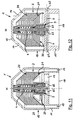
Figuren 3 und 4 dargestellten Längsschnitte des Zentrifugalabscheiders 1 gemäß den Schnittlinien A-A und B-B inFigur 2 wird der innere Aufbau des Zentrifugalabscheiders 1 deutlich. Im Inneren des Gehäuses 10 ist ein Rotor 2 auf einer Achse 4 mit Hilfe von zwei Lagern 51, 52 drehbar gelagert. Der Rotor 2 umfasst dabei einen Abscheiderteil 20 und einen Trägerteil 21. Der Abscheiderteil 20 besteht aus einem Tellerstapel 26 an sich bekannter Ausführung, wobei der Tellerstapel 26 auf einer Tellerauflage 25 aufliegt und nach oben hin durch einen Deckteller 27 abgedeckt ist. Die Anordnung aus Tellerauflage 25, Tellerstapel 26 und Deckteller 27 wird durch eine Schraubenfeder 28 zusammengedrückt, so dass die Anordnung zueinander eine stabile Lage einnimmt. Der Trägerteil 21 besitzt einen nach oben aufragenden hülsenförmigen Abschnitt 24', auf den der Abscheiderteil 20 von oben her aufgesteckt und verdrehfest gesichert ist. - Zum Antreiben des Rotors 2 dient hier ein Elektromotor 3, der unterhalb des Rotors 2 angeordnet ist. Der Elektromotor 3 besitzt einen den unteren Abschnitt 42 der Achse 4 umgebenden Ständer 32, zum Beispiel eine elektromagnetische Spulenanordnung. Um den Ständer 32 herum ist ein Läufer 31 angeordnet, der beispielsweise durch eine Magnethülse gebildet ist. Der Läufer 31 ist verdrehfest mit einem hülsenförmigen Abschnitt 24 des Trägerteils 21 des Rotors 2 verbunden. Bei Versorgung des Elektromotors 3 mit elektrischer Energie wird auf diese Weise der Rotor 2 in die für seine Funktion erforderliche Rotation um die Achse 4 versetzt.
- Um die in dem Elektromotor 3 bei dessen Betrieb entstehende Wärme abzuführen und eine Überhitzung und Schädigung des Elektromotors 3 zu vermeiden, ist der Trägerteil 21 des Rotors 2 hier gleichzeitig als Kühlkörper 30 für den Elektromotor 3 ausgebildet. Der Trägerteil 21 besitzt dazu neben dem in unmittelbarem, wärmeleitendem Kontakt mit dem Elektromotor 3 stehenden hülsenförmigen Abschnitt 24 mehrere in Umfangsrichtung voneinander beabstandete Flügel 22, die die Fläche des Trägerteils 21 vergrößern und somit einen wirksamen Kühlkörper 30 bilden. Bei der Rotation des Rotors 2 wird der Kühlkörper 30 von dem den Zentrifugalabscheider 1 durchströmenden, zu reinigenden Medium überströmt, wodurch die von dem Elektromotor 3 abgegebene Wärme aus diesem abtransportiert und an das den Zentrifugalabscheider 1 durchströmende Medium übertragen wird.
- Die Achse 4 ist mit ihrem unteren Ende 41 mit dem Unterteil 11 des Gehäuses 10 lagefest verbunden. Das obere Ende 43 der Achse 4 ist in einer Zentrieraufnahme 17 an der Unterseite des Deckels 12 zentriert.
- Mittels einer zwischen den Lagern 51 und 52 angeordneten Schraubendruckfeder 50 wird ein Spiel in Längsrichtung zwischen den Lagern 51, 52 ausgeglichen, wobei hier das eine Lager 51 ein Loslager und das andere Lager 52 ein Festlager ist. Das untere Lager 51 ist dabei durch einen darunter angeordneten, mit der Achse 4 verbundenen Sprengring 53 in seiner Beweglichkeit nach axial unten begrenzt. Oberhalb des oberen Lagers 52 ist auf dem oberen Bereich 43 der Achse 4 eine Sicherungshülse 54 angebracht.
- Zur Zuführung des im Zentrifugalabscheiders 1 zu reinigenden Mediums, wie Kurbelgehäuseentlüftungsgas, dient der in
Figur 4 sichtbare Einlass 13 im oberen Bereich des Unterteils 11, durch welchen das Medium in den Innenraum des Deckels 12 zur Unterseite des Rotors 2 gelangt. Vor dort strömt das zu reinigende Medium in bekannter Weise im Rotor in Axialrichtung nach oben und verteilt sich so auf die Zwischenräume zwischen den Tellern des Tellerstapels 26. Durch den rotierenden Abscheiderteil 20 gelangt das zu reinigende Medium in Radialrichtung nach außen, wobei durch dabei entstehende Zentrifugalkräfte flüssige und/oder feste Partikel aus dem Medium entfernt werden. Das gereinigte Medium strömt dann radial außen von dem Rotor 2 nach oben und verlässt den Zentrifugalabscheider 1 durch die inFigur 4 sichtbaren Auslässe 14, die im Deckel 12 angebracht sind. Die abgeschiedenen Partikel gelangen unter Schwerkrafteinfluss in den Auslass 15 und werden von dort abgeführt, beispielsweise als abgeschiedenes Schmieröl in den Ölsumpf einer zugehörigen Brennkraftmaschine, mit der der Zentrifugalabscheider 1 mittels des Verbindungsflansches 18 verbindbar bzw. verbunden ist. -
Figur 5 zeigt einen zweiten Zentrifugalabscheider 1 in Seitenansicht. In seiner äußeren Form entspricht dabei der Zentrifugalabscheider 1 im Wesentlichen dem Beispiel gemäßFigur 1 . Unterschiedlich ist bei dem Abscheider 1 nachFigur 5 , dass hier ein eigenes Kühlmittel durch den Zentrifugalabscheider 1 führbar ist. Hierzu ist im Unterteil 11 gemäßFigur 5 an der rechten Seite ein Kühlmittelkanalanschluss 61 ausgebildet. Dieser Anschluss 61 steht mit einem inFigur 5 nicht sichtbaren, im Inneren des Zentrifugalabscheiders 1 verlaufenden Kühlmittelkanal in Verbindung. Das andere Ende des Kühlmittelkanals mündet in einen zweiten Kühlmittelkanalanschluss 62, der hier zentral an der Oberseite des Deckels 12 ausgebildet ist. Über die Anschlüsse 61 und 62 ist mittels nicht dargestellter Leitungen ein separates Kühlmittel zu- und abführbar, z.B. Kühlwasser oder Schmieröl oder Kraftstoff der zugehörigen Brennkraftmaschine. - An der Unterseite des Gehäuses 10 bzw. dessen Unterteils 11 ist wieder der Verbindungsflansch 18 vorgesehen.
- In der in
Figur 6 dargestellten Unteransicht des Zentrifugalabscheiders 1 ausFigur 5 wird die Anordnung des Einlasses 13 für das Rohmedium und des Auslasses 15 für das abgeschiedene Medium sichtbar. Rechts von dem Rohmediumeinlass 13 ist hier der Verlauf eines Abschnitts des Kühlmittelkanals 6 sichtbar, der zu einer aktiven Kühlung des Elektromotors des Zentrifugalabscheiders 1 dient, wie aus denFiguren 7 und 8 deutlicher wird. - Die
Figuren 7 und 8 zeigen den Zentrifugalabscheider aus denFiguren 5 und 6 in zwei Längsschnitten. Der Rotor 2 im Inneren des Gehäuses 10 entspricht dabei dem des Zentrifugalabscheiders 1 nach denFiguren 1 bis 4 ; auf deren Beschreibung wird diesbezüglich verweisen. - Unterschiedlich zu dem zuvor beschriebenen Ausführungsbeispiel ist bei dem Zentrifugalabscheider 1 nach den
Figuren 5 bis 8 der Kühlmittelkanal 6. Wie dieFigur 8 zeigt, beginnt der Kühlmittelkanal 6 an dem Kühlmittelkanalanschluss 61 radial außen am Unterteil 11 des Gehäuses 10 und läuft von dort zunächst radial nach innen bis zur Mitte des Unterteils 11. Dort trifft der Kühlmittelkanal 6 auf die Achse 4, die hier als Hohlachse ausgeführt ist, so dass der Kühlmittelkanal 6 in seinem weiteren Verlauf in Axialrichtung nach oben durch die Achse 4 verläuft. Im Zentrum des Deckels 12 liegt der zweite Kühlmittelkanalanschluss 62, durch den das Kühlmittel abgeführt werden kann. Ein in der Achse 4 zentral durch den Elektromotor 3 verlaufender Abschnitt des Kühlmittelkanals 6 bildet eine Kühlzone 60, in der Wärme aus dem Elektromotor 3 an das den Kühlmittelkanal 6 durchströmende Kühlmittel abgegeben und dann mit diesem abgeführt werden kann. Die Strömungsrichtung des Kühlmittels im Kühlmittelkanal 6 kann natürlich auch umgekehrt verlaufen. - In seinen weiteren Einzelteilen entspricht der Zentrifugalabscheider 1 gemäß den
Figuren 5 bis 8 dem ersten Ausführungsbeispiel gemäß denFiguren 1 bis 4 ; auf deren Beschreibung wird verwiesen. - In
Figur 9 ist ein drittes Ausführungsbeispiel des Zentrifugalabscheiders 1 in Seitenansicht dargestellt. Die Grundform des Zentrifugalabscheiders 1 gemäßFigur 9 entspricht wieder derjenigen der Ausführungsbeispiele nach denFiguren 1 und5 . - Auch bei dem Zentrifugalabscheider 1 gemäß
Figur 9 ist in dessen Innerem ein Kühlmittelkanal vorgesehen. Die beiden Kühlmittelkanalanschlüsse 61 und 62 zur Zuführung und Abführung des Kühlmittels sind hier einander diametral gegenüberliegend am Unterteil 11 in dessen Umfangsfläche angeordnet. - Die Unteransicht gemäß
Figur 10 zeigt die Anordnung des Einlasses 13 für das Rohmedium und des Auslasses 15 für das abgeschiedene Medium bei dem Abscheider 1 gemäßFigur 9 . Weiterhin wird inFigur 10 der Verlauf des Kühlmittelkanals 6 mit der hier in Radialrichtung gesehen zentralen Kühlzone 60 erkennbar. - Die Unterseite des Gehäuses 10 bildet auch hier wieder den Anschlussflansch 18 zur Verbindung des Zentrifugalabscheider 1 mit einer zugehörigen Brennkraftmaschine oder einem Funktionsmodul der Brennkraftmaschine.
- Die zwei Längsschnitte gemäß den Schnittlinien A-A und B-B in
Figur 10 sind in denFiguren 11 und 12 dargestellt. Der Rotor 2 des Zentrifugalabscheiders 1 ist auch bei diesem dritten Ausführungsbeispiel übereinstimmend mit den Rotoren 2 der beiden zuvor beschriebenen Ausführungsbeispielen ausgeführt; auf die diesbezügliche vorhergehende Beschreibung wird verwiesen. - In
Figur 11 ist der Einlass 13 zur Zuführung des zu reinigenden Rohmediums zum Rotor 2 sichtbar. Radial außen im Unterteil 11 ist der Auslass 15 für das abgeschiedene Medium sichtbar. Die Unterseite des Unterteils 11 bildet wieder den Anschlussflansch 18. -
Figur 12 zeigt den Verlauf des Kühlmittelkanals 6 durch das Unterteil 11 des Gehäuses 10. Links an dem Unterteil 11 liegt an dessen Umfangsfläche der Kühlmittelkanalanschluss 61 zur Zuführung des Kühlmittels. Von dort führt der Kühlmittelkanal 6 in Radialrichtung nach innen, wo er in eine ringförmige Kühlzone 60 mündet. An der gegenüberliegenden Seite des Unterteils 11 befindet sich der zweite Kühlmittelkanalanschluss 62, der mit einem von der Kühlzone 60 nach radial außen verlaufenden zweiten Abschnitt des Kühlmittelkanals 6 verbunden ist und zur Abführung des Kühlmittels dient. - Die ringförmige Kühlzone 60 des Kühlmittelkanals 6 verläuft unterhalb des Elektromotors 3 und das Kühlmedium kann somit Wärme aus dem Elektromotor 3 wirksam aufnehmen und abführen. Zur Vermeidung von Schäden am Elektromotor durch das Kühlmedium ist hier selbstverständlich eine entsprechende Abdichtung vorgesehen.
- Zur Abführung des gereinigten Mediums aus dem Zentrifugalabscheider 1 dienen die beiden in
Figur 12 sichtbaren Auslässe 14 an der Oberseite des Deckels 12. - In seinen weiteren Teilen entspricht der Zentrifugalabscheider 1 den zuvor beschriebenen Ausführungsbeispielen, auf deren Beschreibung verwiesen wird.
-
Figur 13 zeigt einen weiteren Zentrifugalabscheider 1, hier in perspektivischer Ansicht, der für die Entölung von Kurbelgehäuseentlüftungsgas einer Brennkraftmaschine vorgesehen ist. Es ist ein Gehäuse 10 des Abscheiders 1 von außen sichtbar, welches eine im Wesentlichen zylindrische Form aufweist. Nach unten ist das Gehäuse 10 durch ein Unterteil 11 abgeschlossen. Oberseitig sitzt auf dem Gehäuse 10 ein Deckel 12. An der inFigur 13 nach rechts hinten weisenden Seite des Gehäuses 10 ist ein Anschlussflansch 18 angeformt, mit dem der Zentrifugalabscheider 1 mit einer zugehörigen Brennkraftmaschine oder mit einem zu der Brennkraftmaschine gehörenden Funktionsmodul, die hier nicht dargestellt sind, verbindbar ist. - Am Unterteil 11 ist ein Einlass 13 für das Rohmedium angeformt, wobei der Einlass 13 hier als radial verlaufender Schlauchanschlussstutzen ausgebildet ist.
- Axial nach unten weisend ist ein Auslass 15 für abgeschiedenes Medium am Unterteil 11 vorgesehen, wobei der Auslass 15 hier ebenfalls als Schlauchanschlussstutzen ausgebildet ist.
- Am Umfang des Gehauses 10 ist ein Druckregelventil 8 angeordnet, durch das das im Abscheider gereinigte Gas zum Auslass 14 für das Reinmedium strömt. Auch der Auslass 14 ist als Schlauchanschlussstutzen ausgeführt. Das Druckregelventil 8 dient zur Regelung des Drucks im Kurbelgehäuse der zugehörigen Brennkraftmaschine.
- Der Deckel 12 ist hier als Kühldeckel 30' ausgebildet und besitzt zu diesem Zweck an seinem Umfang eine Anzahl von Kühlrippen oder-flügeln. Dabei ist der Kühldeckel 30' in zwei thermisch voneinander getrennte Deckelteile 30.1' und 30.2' unterteilt. Der eine Deckelteil 30.1' ist dabei wärmeleitend mit einem im oberen Bereich des Inneren des Gehäuses 10 angeordneten, hier nicht sichtbaren Elektromotor-Kühlkörper oder anderen wärmeabgebenden Teil eines Elektromotors verbunden. Der andere Deckelteil 30.2' ist wärmeleitend mit einer ebenfalls im oberen Bereich des Inneren des Gehäuses 10 angeordneten, hier nicht sichtbaren Elektronikeinheit des Elektromotors verbunden. Somit werden hier der Elektromotor und dessen Elektronikeinheit weitgehend ohne gegenseitige Beeinflussung gekühlt.
- In der Oberseite des Deckels 12 bzw. 30' ist schließlich noch ein elektrischer Anschluss 16 vorgesehen, z.B eine Buchse für ein Stromversorgungskabel des Elektromotors.
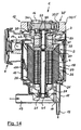
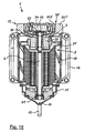
- Anhand der in den
Figuren 14 und15 dargestellten Längsschnitte des Zentrifugalabscheiders 1 gemäßFigur 13 wird dessen innerer Aufbau erkennbar. Im Inneren des Gehäuses 10 ist ein Rotor 2 mit einer Achse 4 mit Hilfe von zwei Lagern 51, 52 drehbar gelagert. Der Rotor 2 umfasst dabei einen Abscheiderteil 20 und einen Trägerteil 21. Der Abscheiderteil 20 besteht aus einem Tellerstapel 26 an sich bekannter Ausführung, wobei der Tellerstapel 26 auf einer Tellerauflage 25 aufliegt und nach oben hin durch einen Deckteller 27 abgedeckt ist. Die Anordnung aus Tellerauflage 25, Tellerstapel 26 und Deckteller 27 wird von unten her durch eine Schraubenfeder 28 zusammengedrückt, so dass die Anordnung zueinander eine stabile Lage einnimmt. - Zum Antreiben des Rotors 2 dient hier ein Elektromotor 3, der oberhalb des Rotors 2 angeordnet ist. Der Elektromotor 3 besitzt einen den oberen Abschnitt 43 der Achse 4 umgebenden Ständer 32, zum Beispiel eine elektromagnetische Spulenanordnung. Um den Ständer 32 herum ist ein Läufer 31 angeordnet, der beispielsweise durch eine Magnethülse gebildet ist. Der Läufer 31 ist hier verdrehfest mit dem oberen Abschnitt 43 der Achse 4 verbunden. Bei Versorgung des Elektromotors 3 mit elektrischer Energie wird auf diese Weise der Rotor 2 zusammen mit der im Gehäuse 10 in den Lagern 51 und 52 drehbar gelagerten Achse 4 in die für seine Funktion erforderliche Rotation versetzt.
- Um die in dem Elektromotor 3 bei dessen Betrieb entstehende Wärme abzuführen und eine Überhitzung und Schädigung des Elektromotors 3 zu vermeiden, ist hier der Ständer 32 des Motors 3 mit einem Kühlkörper 30 für den Elektromotor 3 ausgebildet. Der Kühlkörper 30 steht dazu mit dem Deckelteil 30.1' in wärmeleitendem Kontakt oder ist mit diesem einstückig ausgebildet. Im Betrieb des Motors 3 wird die von dem Elektromotor 3 abgegebene Wärme aus diesem durch den Kühlkörper 30 und den Deckelteil 30.1' abtransportiert und an die den Deckelteil 30.1' umgebende oder umströmende Luft übertragen.
- Über dem Motor 3 ist dessen Elektronikeinheit 34 angeordnet, die ebenfalls im Betrieb Verlustwärme produziert. Zu deren Abführung dient der zweite Deckelteil 30.2', der einen radial inneren Teil des Kühldeckels 30' bildet und der in wärmeleitendem Kontakt mit der Elektronikeinheit 34 steht.
- Die Achse 4 ist mit ihrem unteren Ende 41 in dem unteren Lager 51 im Unterteil 11 des Gehäuses 10 drehbar gelagert. In ihrem oberen Bereich 43 ist die Achse 4 in dem oberen Lager 52 drehbar gelagert. Mittels einer unter dem Lager 52 angeordneten Schraubendruckfeder 50 wird ein Spiel in Längsrichtung zwischen den Lagern 51 und 52 ausgeglichen, wobei hier das eine Lager ein Loslager und das andere Lager ein Festlager ist.
- Zur Zuführung des im Zentrifugalabscheiders 1 zu reinigenden Mediums, wie Kurbelgehäuseentlüftungsgas einer Brennkraftmaschine, dient der in
Figur 14 sichtbare Einlass 13 im Unterteil 11, durch welchen das Medium in den Innenraum des Unterteils 12 und zur Unterseite des Rotors 2 gelangt. Vor dort strömt das zu reinigende Medium im Rotor 2 in Axialrichtung nach oben und verteilt sich auf die Zwischenräume zwischen den Tellern des Tellerstapels 26. Durch den rotierenden Abscheiderteil 20 gelangt das zu reinigende Medium in Radialrichtung nach außen, wobei durch dabei entstehende Zentrifugalkräfte flüssige und/oder feste Partikel aus dem Medium entfernt werden. Das gereinigte Medium strömt dann radial außen von dem Rotor 2 nach oben und verlässt den Zentrifugalabscheider 1 durch die inFigur 14 sichtbaren Auslass 14, der in dem seitlich am Gehäuse 10 angebrachten Druckregelventil 8 liegt. Die abgeschiedenen Partikel gelangen unter Schwerkrafteinfluss in den Auslass 15 und werden von dort abgeführt, beispielsweise als abgeschiedenes Schmieröl in den Ölsumpf einer zugehörigen Brennkraftmaschine zurückgeführt. - Wie schon beschrieben, besitzt das Gehäuse 10 das Unterteil 11 mit dem Einlass 13 für dem Rotor 2 zuzuführendes Rohmedium und mit dem Auslass 15 für aus dem Rohmedium abgeschiedenes Medium. Zwischen einem im Einbauzustand tiefsten Bereich des Einlasses 13 und dem Auslass 15 ist hier ein als oder mit einer Drossel ausgebildeter, zum Auslass 15 nicht ansteigender Verbindungskanal 19 vorgesehen. Der Verbindungskanal 19 dient zum Ableiten von Flüssigkeiten, die sich schon im Einlass 13 aus einem dem Abscheider 1 zuströmenden Gas niederschlagen und sammeln. Da der Verbindungskanal 19 nur einen kleinen Querschnitt hat, stört er die Gasströmung im Abscheider 1 nicht.
- Weiterhin sind auf einer den Rotor 2 umgebenden Innenumfangsfläche des Gehäuses 10 mehrere Flüssigkeitsleitrinnen 101 angeordnet ist, die schraubenlinienförmig in Drehrichtung des Rotors 2 gesehen nach unten verlaufen und die nach unten hin offen sind. Im Querschnitt gesehen sind die Flüssigkeitsleitrinnen 101 durch L-Profile mit zunächst radial nach innen und dann nach unten verlaufenden Schenkeln gebildet. Diese Flüssigkeitsleitrinnen 101 nehmen bei einer Gasreinigung die sich auf der Innenumfangsfläche des Gehäuses 10 niederschlagende Flüssigkeit auf und leiten sie, unterstützt durch die Schwerkraft und durch die Rotation des Rotors 2 und die dadurch erzeugte rotierende Gasströmung, entlang der Schraubenlinie nach unten, von wo aus die Flüssigkeit aus dem Abscheider 10 durch den Auslass 15 abgeführt wird.
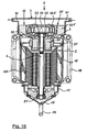
- Die
Figur 16 zeigt schließlich eine Ausführung des Zentrifugalabscheiders 1, der im Wesentlichen der Ausführung nach denFiguren 13 bis 15 entspricht. Unterschiedlich ist, dass der Abscheider 1 nachFigur 16 im Bereich seines Kühldeckels 30' einen Aufsatz 7 trägt, der zur Kühlung der Deckelteile 30.1' und 30.2' mittels eines durch den Aufsatz 7 geleiteten fluiden Kühlmediums dient. Dazu hat der Aufsatz 7 an seiner einen Seite einen Zulauf 71 und diametral gegenüber einen Ablauf 72 für das fluide Kühlmedium. Das Kühlmedium kann z.B. Kühlwasser der zugehörigen Brennkraftmaschine sein und der Aufsatz 7 kann über seinen Zulauf 71 und Ablauf 72 mittels Verbindungsleitungen in den Kühlwasserkreislauf eingefügt sein. - In seinen weiteren Teilen entspricht der Zentrifugalabscheider 1 nach
Figur 16 dem Beispiel nach denFiguren 13 bis 15 und es wird daher auf deren Beschreibung verwiesen.
Claims (18)
- Zentrifugalabscheider (1) zum Abscheiden von Ölnebel aus dem Kurbelgehäuseentlüftungsgas einer Brennkraftmaschine oder zum Abscheiden von festen Verunreinigungen aus dem Schmieröl einer Brennkraftmaschine, wobei der Zentrifugalabscheider (1) einen drehantreibbaren Rotor (2), ein den Rotor (2) aufnehmendes Gehäuse (10) und einen Drehantrieb für den Rotor (2) aufweist, wobei der Drehantrieb durch einen Elektromotor (3) gebildet ist, der im Gehäuse (10) angeordnet ist, wobei der Zentrifugalabscheider (1) Mittel zum Kühlen des Elektromotors (3) aufweist und wobei mindestens ein Kühlkörper (30) als Mittel zum Kühlen des Elektromotors (3) vorgesehen ist,
dadurch gekennzeichnet,
dass der Kühlkörper (30) direkt mit einem Ständer des Elektromotors (3) verbunden ist oder diesen ausbildet. - Zentrifugalabscheider nach Anspruch 1, dadurch gekennzeichnet, dass der Kühlkörper (30) im Betrieb des Zentrifugalabscheiders (1) von dem Kurbelgehäuseentlüftungsgas oder dem Kühlmittel oder dem Schmieröl oder dem Kraftstoff oder von Kühlluft der Brennkraftmaschine oder von Umgebungsluft überströmbar und/oder durchströmbar ist.
- Zentrifugalabscheider nach Anspruch 1 oder 2, dadurch gekennzeichnet, dass der Kühlkörper (30) mehrere Flügel (22) aufweist.
- Zentrifugalabscheider nach Anspruch 3, dadurch gekennzeichnet, dass der Kühlkörper (30) rotationssymmetrisch ist und dass die Flügel (22) radial ausgerichtet und über den Umfang des Kühlkörpers (30) verteilt sind.
- Zentrifugalabscheider nach einem der Ansprüche 1 bis 4, dadurch gekennzeichnet, dass der Kühlkörper (30) ein einstückiges Metallteil, vorzugsweise ein Druckgusstell aus Leichtmetail, insbesondere Aluminium oder Magnesium, ist.
- Zentrifugalabscheider nach einem der Ansprüche 1 bis 5, dadurch gekennzeichnet, dass das-Gehäuse (10) ein einstückiges Kunststoffteil, vorzugsweise ein Spritzgusstell aus einem Thermoplasten, insbesondere Polyamid, ist.
- Zentrifugalabschelder nach einem der Ansprüche 1 bis 6, dadurch gekennzeichnet, dass der Elektromotor (3) auf einer Reingasseite des Zentritugalabschelders (1) angeordnet ist.
- Zentrifugalabscheider nach einem der Ansprüche 1 bis 7, dadurch gekennzeichnet, dass der Elektromotor (3) an einer von außen zugänglichen, im montierten Zustand außerhalb der zugehörigen Brennkraftmaschine liegenden Oberseite des Zentrifugalabscheiders (1) angeordnet ist.
- Zentrifugalabscheider nach Anspruch 8, dadurch gekennzeichnet, dass der Kühlkörper (30) als ein die Oberseite des Zentrifugalabscheiders (1) bildender Deckel (30') ausgeführt Ist.
- Zentrifugalabscheider nach Anspruch 9, dadurch gekennzeichnet, dass der Deckel (30') eine zum Elektromotor (3) gehörende Elektronikeinheit (34) aufnimmt oder enthält.
- Zentrifugalabscheider nach Anspruch 10, dadurch gekennzeichnet, dass der Deckel (30') in zwei thermisch voneinander getrennte Deckelteile (30.1', 30.2') unterteilt ist und dass ein erster Deckelteil (30.1') in wärmeleitender Verbindung mit dem Elektromotor (3) und ein zweiter Deckelteil (30.2') in wärmeleitender Verbindung mit der Elektronikeinheit (34) steht.
- Zentrifugalabscheider nach Anspruch 10 oder 11, dadurch gekennzeichnet, dass der Elektromotor (3) und die Elektronikeinheit (34) durch ein thermisches Isolationselement (35) voneinander getrennt sind.
- Zentrifugalabscheider nach einem der Ansprüche 9 bis 12, dadurch gekennzeichnet, dass mit dem Deckel (30') ein Aufsatz (7) mit je einem Zulauf (71) und Ablauf (72) für eine den Deckel (30') überströmende Kühlflüssigkeit verbindbar oder verbunden ist.
- Zentrifugalabscheider nach einem der Ansprüche 1 bis 13, dadurch gekennzeichnet, dass das Gehäuse (10) ein Unterteil (11) mit einem Einlass (13) für dem Rotor (2) zuzuführendes Rohmedium und mit einem Auslass (15) für aus dem Rohmedium abgeschiedenes Medium aufweist, wobei das Unterteil (11) als separates Einzelteil herstellbar und relativ zum übrigen Gehäuse (10) mit diesem in verschiedenen Verdrehstellungen verbindbar, vorzugsweise verschweißbar oder zusammensteckbar, ist.
- Zentrifugalabscheider nach einem der Ansprüche 1 bis 13, dadurch gekennzeichnet, dass das Gehäuse (10) ohne Unterteil (11) ausgeführt und unter Abdichtung durch Dichtungen in einen Modulsockel, insbesondere eines Ölfiltermoduls, oder in eine Zylinderkopfhaube der Brennkraftmaschine einsteckbar oder einschraubbar ist.
- Zentrifugalabscheider nach einem der Ansprüche 1 bis 15, dadurch gekennzeichnet, dass ein Anschlusssflansch (18) vorgeschen ist, mit dem der Zentrifugalabscheider an einen Modulsockel, insbesondere eines Ölfiltermoduls, oder an eine Zylinderkopfhaube der Brennkraftmaschine anflanschbar ist, wobei durch den Anschlussflansch (18) ein Teil der oder alle benötigten Strömungsverbindungen von und zu der Brennkraftmaschine verlaufen.
- Zentrifugalabscheider nach Anspruch 16, dadurch gekennzeichnet, dass über den Anschlussflansch (18) zugleich eine elektrische Verbindung zur Stromversorgung des Elektromotors (3) herstellbar ist.
- Zentrifugalabscheider nach einem der Ansprüche 1 bis 17, dadurch gekennzeichnet, dass die Drehzahl des den Rotor (2) antreibenden elektromotors (3) nach Maßgabe des Volumenstroms des Kurbelgehäuseentlüftungsgases veränderbar ist.
Applications Claiming Priority (3)
| Application Number | Priority Date | Filing Date | Title |
|---|---|---|---|
| DE202008014734U DE202008014734U1 (de) | 2008-11-06 | 2008-11-06 | Zentrifugalabscheider |
| DE102009036476A DE102009036476A1 (de) | 2008-11-06 | 2009-08-07 | Zentrifugalabscheider |
| PCT/EP2009/007927 WO2010051994A1 (de) | 2008-11-06 | 2009-11-05 | Zentrifugalabschneider |
Publications (2)
| Publication Number | Publication Date |
|---|---|
| EP2352573A1 EP2352573A1 (de) | 2011-08-10 |
| EP2352573B1 true EP2352573B1 (de) | 2013-07-03 |
Family
ID=42055450
Family Applications (1)
| Application Number | Title | Priority Date | Filing Date |
|---|---|---|---|
| EP09764178.1A Revoked EP2352573B1 (de) | 2008-11-06 | 2009-11-05 | Zentrifugalabscheider |
Country Status (4)
| Country | Link |
|---|---|
| US (1) | US20110281712A1 (de) |
| EP (1) | EP2352573B1 (de) |
| DE (2) | DE202008014734U1 (de) |
| WO (1) | WO2010051994A1 (de) |
Families Citing this family (38)
| Publication number | Priority date | Publication date | Assignee | Title |
|---|---|---|---|---|
| US8893689B2 (en) | 2010-01-27 | 2014-11-25 | Cummins Filtration Ip, Inc. | Crankcase ventilation self-cleaning coalescer with intermittent rotation |
| US8940068B2 (en) * | 2010-01-27 | 2015-01-27 | Cummins Filtration Ip Inc. | Magnetically driven rotating separator |
| US8974567B2 (en) | 2010-01-27 | 2015-03-10 | Cummins Filtration Ip Inc. | Rotating coalescer with keyed drive |
| US9194265B2 (en) | 2010-01-27 | 2015-11-24 | Cummins Filtration Ip, Inc. | Rotating separator with housing preventing separated liquid carryover |
| US8807097B2 (en) | 2010-01-27 | 2014-08-19 | Cummins Filtration Ip Inc. | Closed crankcase ventilation system |
| SE534773C2 (sv) * | 2010-04-09 | 2011-12-13 | Alfa Laval Corp Ab | Centrifugalseparator anordnad inuti en förbränningsmotor |
| DE102011009741B4 (de) * | 2010-07-30 | 2021-06-02 | Hengst Se | Zentrifugalabscheider mit Partikelleitrinne |
| DE102011076465B4 (de) | 2011-05-25 | 2021-04-29 | Hengst Se | Zentrifugalabscheider zum Abscheiden von Ölnebel aus dem Kurbelgehäuseentlüftungsgas einer Brennkraftmaschine |
| BR112014009743A2 (pt) | 2011-11-04 | 2017-05-02 | Cummins Filtration Ip Inc | separador giratório para separar líquido de mistura fluida |
| EP3112031B1 (de) * | 2014-02-25 | 2025-03-26 | Tokyo Roki Co., Ltd. | Ölabscheider |
| US10569206B2 (en) * | 2014-02-26 | 2020-02-25 | Tokyo Roki Co., Ltd. | Oil separator |
| WO2015145646A1 (ja) * | 2014-03-27 | 2015-10-01 | 東京濾器株式会社 | オイルセパレータ |
| EP2939746B1 (de) | 2014-04-30 | 2016-09-07 | Alfa Laval Corporate AB | Zentrifugalabscheider |
| EP2939747B1 (de) | 2014-04-30 | 2016-08-03 | Alfa Laval Corporate AB | Zentrifugalabscheider |
| US10322362B2 (en) * | 2014-09-25 | 2019-06-18 | Tokyo Roki Co., Ltd. | Oil separator |
| WO2017053267A1 (en) | 2015-09-24 | 2017-03-30 | Cummins Filtration Ip, Inc. | Utilizing a mechanical seal between a filter media and an end cap of a rotating filter cartridge |
| DE102015119616A1 (de) | 2015-11-13 | 2017-05-18 | Hengst Se & Co. Kg | Rotor eines Zentrifugalabscheiders |
| DE202016104755U1 (de) | 2016-08-30 | 2017-12-04 | Reinz-Dichtungs-Gmbh | Ölabscheider, Entlüftungssystem und Verbrennungsmotor |
| DE202016104754U1 (de) * | 2016-08-30 | 2017-12-04 | 3Nine Ab | Ölabscheider, Entlüftungssystem für einen Verbrennungsmotor sowie Verbrennungsmotor mit einem derartigen Ölabscheider |
| DE202016106867U1 (de) * | 2016-12-09 | 2018-03-12 | 3Nine Ab | Ölabscheider mit Wellenlagerung zwischen Antriebs- und Abscheidekammer |
| DE102016124098A1 (de) * | 2016-12-12 | 2018-06-14 | Hengst Se & Co. Kg | Verfahren zum Schutz eines Rotationsseparators gegen Vereisung |
| DE102017200848A1 (de) | 2017-01-19 | 2018-07-19 | Mahle International Gmbh | Abscheideeinrichtung |
| DE102017201898A1 (de) | 2017-02-07 | 2018-08-09 | Mahle International Gmbh | Abscheideeinrichtung |
| DE102017205852B3 (de) | 2017-04-06 | 2018-05-17 | Audi Ag | Tellerseparator |
| DE102017210321A1 (de) * | 2017-06-20 | 2018-12-20 | Elringklinger Ag | Abscheidevorrichtung |
| DE112018002354T5 (de) | 2017-06-20 | 2020-01-23 | Cummins Filtration Ip, Inc. | Axialstromzentrifugalabscheider |
| DE102017210322A1 (de) * | 2017-06-20 | 2018-12-20 | Elringklinger Ag | Abscheidevorrichtung |
| DE102018106881B4 (de) | 2018-03-22 | 2019-10-10 | Bayerische Motoren Werke Aktiengesellschaft | Absaugvorrichtung zur Kurbelgehäuseentlüftung |
| EP3801828B1 (de) | 2018-05-24 | 2025-11-26 | Cummins Filtration IP, Inc. | Verdrehsicherung für kurbelgehäuseentlüftungsfilter |
| CN109107779A (zh) * | 2018-09-30 | 2019-01-01 | 合肥恒信汽车发动机部件制造有限公司 | 一种主动式碟片离心分离器的分离碟片固定机构 |
| DE102020117515A1 (de) * | 2020-07-02 | 2022-01-05 | Ebm-Papst St. Georgen Gmbh & Co. Kg | Zentrifugalabscheider |
| US11904328B2 (en) * | 2021-08-30 | 2024-02-20 | Spinesmith Partners, L.P. | Induction powered vortex fluid separator |
| EP4198271B1 (de) | 2021-12-17 | 2024-07-10 | Alfdex AB | Kurbelgehäusegastrenner |
| DE102022105881A1 (de) | 2022-03-14 | 2023-09-14 | Hengst Se | Rotationsabscheider zum Abscheiden von flüssigen Partikeln aus einem Heißgas |
| DE102022105880A1 (de) | 2022-03-14 | 2023-09-14 | Hengst Se | Rotationsabscheider zum Abscheiden von flüssigen Partikeln aus einem Heißgas |
| EP4336021B1 (de) | 2022-09-12 | 2025-04-09 | Alfdex AB | Kurbelgehäusegasabscheider |
| CN115450729B (zh) * | 2022-10-24 | 2023-11-03 | 苏州恩都法汽车系统股份有限公司 | 一种离心式油气分离器和发动机系统 |
| CN116116111B (zh) * | 2022-10-28 | 2025-07-04 | 苏州恩都法汽车系统股份有限公司 | 一种离心式油气分离装置 |
Family Cites Families (14)
| Publication number | Priority date | Publication date | Assignee | Title |
|---|---|---|---|---|
| US2553936A (en) * | 1948-07-02 | 1951-05-22 | Ben F Patrick | Reclaiming machine |
| US3572509A (en) * | 1969-06-19 | 1971-03-30 | Auto Life Products Inc | Tissue roll oil filter assembly |
| US3706412A (en) * | 1971-07-28 | 1972-12-19 | Haemonetics Corp | Pressure-actuated centrifuge chuck and centrifuge incorporating the same |
| DE2245019C3 (de) * | 1972-09-14 | 1980-06-04 | Maschinenfabrik Buckau R. Wolf Ag, 4048 Grevenbroich | Kontinuierlich arbeitende Zuckerzentrifuge |
| US5069413A (en) * | 1988-04-11 | 1991-12-03 | E. I. Du Pont De Nemours And Company | Centrifuge motor mount having two slotted members |
| CA2087763C (en) * | 1992-02-11 | 2002-07-02 | Jimmy Cochimin | Stator frame for dynamoelectric machine and method for making same |
| US6213929B1 (en) * | 1998-09-25 | 2001-04-10 | Analytical Engineering, Inc. | Motor driven centrifugal filter |
| SE515302C2 (sv) * | 1999-11-15 | 2001-07-09 | Alfa Laval Ab | Ett sätt och en apparat för rening av gas |
| DE10300976A1 (de) * | 2002-01-17 | 2003-07-31 | Mann & Hummel Filter | Zentrifuge zum Abscheiden von Partikeln aus einem Fluidstrom |
| DE10226695A1 (de) * | 2002-06-15 | 2003-12-24 | Daimler Chrysler Ag | Zentrifugal-Ölabscheider in einem Kurbelgehäuse einer Brennkraftmaschine |
| SE0201982D0 (sv) * | 2002-06-24 | 2002-06-24 | Alfa Laval Corp Ab | Sätt att rena vevhusgas samt en gasreningsseparator |
| SE525432C2 (sv) * | 2003-02-17 | 2005-02-22 | Alfa Laval Corp Ab | Sätt att behandla luft ombord på ett fordon och en anordning för användning vid genomförande av sättet |
| DE20302824U1 (de) * | 2003-02-21 | 2004-07-08 | Hengst Gmbh & Co.Kg | Ölabscheider für die Reinigung von Ölnebel enthaltendem Kurbelgehäuseentlüftungsgas einer Brennkraftmaschine |
| SE525981C2 (sv) | 2003-10-07 | 2005-06-07 | 3Nine Ab | Anordning vid en centrifugalseparator |
-
2008
- 2008-11-06 DE DE202008014734U patent/DE202008014734U1/de not_active Expired - Lifetime
-
2009
- 2009-08-07 DE DE102009036476A patent/DE102009036476A1/de not_active Withdrawn
- 2009-11-05 WO PCT/EP2009/007927 patent/WO2010051994A1/de not_active Ceased
- 2009-11-05 US US13/127,622 patent/US20110281712A1/en not_active Abandoned
- 2009-11-05 EP EP09764178.1A patent/EP2352573B1/de not_active Revoked
Also Published As
| Publication number | Publication date |
|---|---|
| DE102009036476A1 (de) | 2010-05-12 |
| EP2352573A1 (de) | 2011-08-10 |
| WO2010051994A1 (de) | 2010-05-14 |
| US20110281712A1 (en) | 2011-11-17 |
| DE202008014734U1 (de) | 2010-03-25 |
Similar Documents
| Publication | Publication Date | Title |
|---|---|---|
| WO2010051994A1 (de) | Zentrifugalabschneider | |
| DE102011076465B4 (de) | Zentrifugalabscheider zum Abscheiden von Ölnebel aus dem Kurbelgehäuseentlüftungsgas einer Brennkraftmaschine | |
| EP1514012B1 (de) | Zentrifugal- labscheider in einem kurbelgeh use einer b rennkraftmaschine | |
| DE102012107107B4 (de) | Aktive Kühlung eines Motors | |
| EP3004649B1 (de) | Pumpenanordnung | |
| DE102015015863A1 (de) | Elektromotorisch angetriebene Flüssigkeitspumpe | |
| WO2014019853A2 (de) | Aktive kühlung eines motors mit integriertem kühlkanal | |
| DE202016106151U1 (de) | Motor mit einem verbesserten Aufbau zur Wärmeableitung | |
| EP2514958B1 (de) | Kraftstofffilter für eine Brennkraftmaschine | |
| WO2015075103A1 (de) | Diagonal- oder axiallüfter mit gekühltem antrieb | |
| EP2225042A1 (de) | Separator mit einem schmiermittelsystem für einen kurzspindelantrieb | |
| DE10356855A1 (de) | Kraftstoffzufuhreinheit | |
| WO1999054051A1 (de) | Freistrahlzentrifuge | |
| DE202016105605U1 (de) | Aufbau eines Motors mit verbesserter Wärmeableitung | |
| DE102017203529A1 (de) | Vorrichtung zur Kühlung einer elektrischen Maschine mit einem Stator und einem Rotor | |
| EP1566547B1 (de) | Flüssigkeitsreibkupplung für einen Kraftfahrzeuglüfter | |
| EP3879105A1 (de) | Pumpeneinsatz und pumpenanordnung mit einem solchen pumpeneinsatz | |
| DE102004005117B4 (de) | Fahrzeugluftkompressorvorrichtung | |
| EP2406498A1 (de) | Regelbare kühlmittelpumpe | |
| DE102010002790B4 (de) | An eine Brennkraftmaschine anflanschbarer Ölnebelabscheider | |
| DE102010002787B4 (de) | Ölnebelabscheider mit einem Ölrückführkanal mit Siphon und Brennkraftmaschine mit Ölnebelabscheider | |
| DE102005010459A1 (de) | Elektromotor | |
| EP2545260A1 (de) | Ölnebelabscheider und brennkraftmaschine mit einem ölnebelabscheider | |
| DE102010055756B4 (de) | Verbrennungsmotor und damit angetriebenes Stromaggregat | |
| EP1774152A1 (de) | Ölmodul mit wasserpumpe und wärmetauscher |
Legal Events
| Date | Code | Title | Description |
|---|---|---|---|
| PUAI | Public reference made under article 153(3) epc to a published international application that has entered the european phase |
Free format text: ORIGINAL CODE: 0009012 |
|
| 17P | Request for examination filed |
Effective date: 20110606 |
|
| AK | Designated contracting states |
Kind code of ref document: A1 Designated state(s): AT BE BG CH CY CZ DE DK EE ES FI FR GB GR HR HU IE IS IT LI LT LU LV MC MK MT NL NO PL PT RO SE SI SK SM TR |
|
| DAX | Request for extension of the european patent (deleted) | ||
| REG | Reference to a national code |
Ref country code: DE Ref legal event code: R079 Ref document number: 502009007486 Country of ref document: DE Free format text: PREVIOUS MAIN CLASS: B01D0045140000 Ipc: F01M0013040000 |
|
| GRAP | Despatch of communication of intention to grant a patent |
Free format text: ORIGINAL CODE: EPIDOSNIGR1 |
|
| RIC1 | Information provided on ipc code assigned before grant |
Ipc: F01M 13/04 20060101AFI20121207BHEP Ipc: B04B 5/12 20060101ALI20121207BHEP |
|
| GRAS | Grant fee paid |
Free format text: ORIGINAL CODE: EPIDOSNIGR3 |
|
| GRAA | (expected) grant |
Free format text: ORIGINAL CODE: 0009210 |
|
| AK | Designated contracting states |
Kind code of ref document: B1 Designated state(s): AT BE BG CH CY CZ DE DK EE ES FI FR GB GR HR HU IE IS IT LI LT LU LV MC MK MT NL NO PL PT RO SE SI SK SM TR |
|
| REG | Reference to a national code |
Ref country code: GB Ref legal event code: FG4D Free format text: NOT ENGLISH |
|
| REG | Reference to a national code |
Ref country code: AT Ref legal event code: REF Ref document number: 619921 Country of ref document: AT Kind code of ref document: T Effective date: 20130715 Ref country code: CH Ref legal event code: EP |
|
| REG | Reference to a national code |
Ref country code: IE Ref legal event code: FG4D Free format text: LANGUAGE OF EP DOCUMENT: GERMAN |
|
| REG | Reference to a national code |
Ref country code: DE Ref legal event code: R096 Ref document number: 502009007486 Country of ref document: DE Effective date: 20130829 |
|
| REG | Reference to a national code |
Ref country code: SE Ref legal event code: TRGR |
|
| PG25 | Lapsed in a contracting state [announced via postgrant information from national office to epo] |
Ref country code: SI Free format text: LAPSE BECAUSE OF FAILURE TO SUBMIT A TRANSLATION OF THE DESCRIPTION OR TO PAY THE FEE WITHIN THE PRESCRIBED TIME-LIMIT Effective date: 20130703 |
|
| REG | Reference to a national code |
Ref country code: NL Ref legal event code: VDEP Effective date: 20130703 |
|
| REG | Reference to a national code |
Ref country code: LT Ref legal event code: MG4D |
|
| PG25 | Lapsed in a contracting state [announced via postgrant information from national office to epo] |
Ref country code: IS Free format text: LAPSE BECAUSE OF FAILURE TO SUBMIT A TRANSLATION OF THE DESCRIPTION OR TO PAY THE FEE WITHIN THE PRESCRIBED TIME-LIMIT Effective date: 20131103 Ref country code: PT Free format text: LAPSE BECAUSE OF FAILURE TO SUBMIT A TRANSLATION OF THE DESCRIPTION OR TO PAY THE FEE WITHIN THE PRESCRIBED TIME-LIMIT Effective date: 20131104 Ref country code: CY Free format text: LAPSE BECAUSE OF FAILURE TO SUBMIT A TRANSLATION OF THE DESCRIPTION OR TO PAY THE FEE WITHIN THE PRESCRIBED TIME-LIMIT Effective date: 20130626 Ref country code: LT Free format text: LAPSE BECAUSE OF FAILURE TO SUBMIT A TRANSLATION OF THE DESCRIPTION OR TO PAY THE FEE WITHIN THE PRESCRIBED TIME-LIMIT Effective date: 20130703 Ref country code: NO Free format text: LAPSE BECAUSE OF FAILURE TO SUBMIT A TRANSLATION OF THE DESCRIPTION OR TO PAY THE FEE WITHIN THE PRESCRIBED TIME-LIMIT Effective date: 20131003 Ref country code: HR Free format text: LAPSE BECAUSE OF FAILURE TO SUBMIT A TRANSLATION OF THE DESCRIPTION OR TO PAY THE FEE WITHIN THE PRESCRIBED TIME-LIMIT Effective date: 20130703 |
|
| PGFP | Annual fee paid to national office [announced via postgrant information from national office to epo] |
Ref country code: SE Payment date: 20131112 Year of fee payment: 5 |
|
| PG25 | Lapsed in a contracting state [announced via postgrant information from national office to epo] |
Ref country code: LV Free format text: LAPSE BECAUSE OF FAILURE TO SUBMIT A TRANSLATION OF THE DESCRIPTION OR TO PAY THE FEE WITHIN THE PRESCRIBED TIME-LIMIT Effective date: 20130703 Ref country code: FI Free format text: LAPSE BECAUSE OF FAILURE TO SUBMIT A TRANSLATION OF THE DESCRIPTION OR TO PAY THE FEE WITHIN THE PRESCRIBED TIME-LIMIT Effective date: 20130703 Ref country code: PL Free format text: LAPSE BECAUSE OF FAILURE TO SUBMIT A TRANSLATION OF THE DESCRIPTION OR TO PAY THE FEE WITHIN THE PRESCRIBED TIME-LIMIT Effective date: 20130703 Ref country code: GR Free format text: LAPSE BECAUSE OF FAILURE TO SUBMIT A TRANSLATION OF THE DESCRIPTION OR TO PAY THE FEE WITHIN THE PRESCRIBED TIME-LIMIT Effective date: 20131004 Ref country code: NL Free format text: LAPSE BECAUSE OF FAILURE TO SUBMIT A TRANSLATION OF THE DESCRIPTION OR TO PAY THE FEE WITHIN THE PRESCRIBED TIME-LIMIT Effective date: 20130703 Ref country code: ES Free format text: LAPSE BECAUSE OF FAILURE TO SUBMIT A TRANSLATION OF THE DESCRIPTION OR TO PAY THE FEE WITHIN THE PRESCRIBED TIME-LIMIT Effective date: 20131014 |
|
| RAP2 | Party data changed (patent owner data changed or rights of a patent transferred) |
Owner name: HENGST SE & CO. KG |
|
| PG25 | Lapsed in a contracting state [announced via postgrant information from national office to epo] |
Ref country code: CY Free format text: LAPSE BECAUSE OF FAILURE TO SUBMIT A TRANSLATION OF THE DESCRIPTION OR TO PAY THE FEE WITHIN THE PRESCRIBED TIME-LIMIT Effective date: 20130703 |
|
| PLBI | Opposition filed |
Free format text: ORIGINAL CODE: 0009260 |
|
| PG25 | Lapsed in a contracting state [announced via postgrant information from national office to epo] |
Ref country code: CZ Free format text: LAPSE BECAUSE OF FAILURE TO SUBMIT A TRANSLATION OF THE DESCRIPTION OR TO PAY THE FEE WITHIN THE PRESCRIBED TIME-LIMIT Effective date: 20130703 Ref country code: SK Free format text: LAPSE BECAUSE OF FAILURE TO SUBMIT A TRANSLATION OF THE DESCRIPTION OR TO PAY THE FEE WITHIN THE PRESCRIBED TIME-LIMIT Effective date: 20130703 Ref country code: RO Free format text: LAPSE BECAUSE OF FAILURE TO SUBMIT A TRANSLATION OF THE DESCRIPTION OR TO PAY THE FEE WITHIN THE PRESCRIBED TIME-LIMIT Effective date: 20130703 Ref country code: EE Free format text: LAPSE BECAUSE OF FAILURE TO SUBMIT A TRANSLATION OF THE DESCRIPTION OR TO PAY THE FEE WITHIN THE PRESCRIBED TIME-LIMIT Effective date: 20130703 Ref country code: DK Free format text: LAPSE BECAUSE OF FAILURE TO SUBMIT A TRANSLATION OF THE DESCRIPTION OR TO PAY THE FEE WITHIN THE PRESCRIBED TIME-LIMIT Effective date: 20130703 |
|
| 26 | Opposition filed |
Opponent name: ALFA LAVAL CORPORATE AB Effective date: 20140401 |
|
| PLAX | Notice of opposition and request to file observation + time limit sent |
Free format text: ORIGINAL CODE: EPIDOSNOBS2 |
|
| PG25 | Lapsed in a contracting state [announced via postgrant information from national office to epo] |
Ref country code: IT Free format text: LAPSE BECAUSE OF FAILURE TO SUBMIT A TRANSLATION OF THE DESCRIPTION OR TO PAY THE FEE WITHIN THE PRESCRIBED TIME-LIMIT Effective date: 20130703 |
|
| BERE | Be: lapsed |
Owner name: HENGST G.M.B.H. & CO. KG Effective date: 20131130 |
|
| REG | Reference to a national code |
Ref country code: DE Ref legal event code: R026 Ref document number: 502009007486 Country of ref document: DE Effective date: 20140401 |
|
| PLAB | Opposition data, opponent's data or that of the opponent's representative modified |
Free format text: ORIGINAL CODE: 0009299OPPO |
|
| REG | Reference to a national code |
Ref country code: CH Ref legal event code: PL |
|
| R26 | Opposition filed (corrected) |
Opponent name: ALFA LAVAL CORPORATE AB Effective date: 20140401 |
|
| PLAF | Information modified related to communication of a notice of opposition and request to file observations + time limit |
Free format text: ORIGINAL CODE: EPIDOSCOBS2 |
|
| GBPC | Gb: european patent ceased through non-payment of renewal fee |
Effective date: 20131105 |
|
| PG25 | Lapsed in a contracting state [announced via postgrant information from national office to epo] |
Ref country code: MC Free format text: LAPSE BECAUSE OF FAILURE TO SUBMIT A TRANSLATION OF THE DESCRIPTION OR TO PAY THE FEE WITHIN THE PRESCRIBED TIME-LIMIT Effective date: 20130703 Ref country code: CH Free format text: LAPSE BECAUSE OF NON-PAYMENT OF DUE FEES Effective date: 20131130 Ref country code: LI Free format text: LAPSE BECAUSE OF NON-PAYMENT OF DUE FEES Effective date: 20131130 |
|
| REG | Reference to a national code |
Ref country code: FR Ref legal event code: ST Effective date: 20140731 |
|
| REG | Reference to a national code |
Ref country code: IE Ref legal event code: MM4A |
|
| PGFP | Annual fee paid to national office [announced via postgrant information from national office to epo] |
Ref country code: DE Payment date: 20140114 Year of fee payment: 5 |
|
| PG25 | Lapsed in a contracting state [announced via postgrant information from national office to epo] |
Ref country code: BE Free format text: LAPSE BECAUSE OF NON-PAYMENT OF DUE FEES Effective date: 20131130 |
|
| PG25 | Lapsed in a contracting state [announced via postgrant information from national office to epo] |
Ref country code: IE Free format text: LAPSE BECAUSE OF NON-PAYMENT OF DUE FEES Effective date: 20131105 |
|
| REG | Reference to a national code |
Ref country code: DE Ref legal event code: R231 Ref document number: 502009007486 Country of ref document: DE |
|
| PG25 | Lapsed in a contracting state [announced via postgrant information from national office to epo] |
Ref country code: FR Free format text: LAPSE BECAUSE OF NON-PAYMENT OF DUE FEES Effective date: 20131202 Ref country code: GB Free format text: LAPSE BECAUSE OF NON-PAYMENT OF DUE FEES Effective date: 20131105 |
|
| REG | Reference to a national code |
Ref country code: SE Ref legal event code: WITD Effective date: 20141121 |
|
| PG25 | Lapsed in a contracting state [announced via postgrant information from national office to epo] |
Ref country code: DE Free format text: LAPSE BECAUSE OF THE APPLICANT RENOUNCES Effective date: 20141108 |
|
| PG25 | Lapsed in a contracting state [announced via postgrant information from national office to epo] |
Ref country code: SM Free format text: LAPSE BECAUSE OF FAILURE TO SUBMIT A TRANSLATION OF THE DESCRIPTION OR TO PAY THE FEE WITHIN THE PRESCRIBED TIME-LIMIT Effective date: 20130703 |
|
| PG25 | Lapsed in a contracting state [announced via postgrant information from national office to epo] |
Ref country code: TR Free format text: LAPSE BECAUSE OF FAILURE TO SUBMIT A TRANSLATION OF THE DESCRIPTION OR TO PAY THE FEE WITHIN THE PRESCRIBED TIME-LIMIT Effective date: 20130703 |
|
| PG25 | Lapsed in a contracting state [announced via postgrant information from national office to epo] |
Ref country code: BG Free format text: LAPSE BECAUSE OF FAILURE TO SUBMIT A TRANSLATION OF THE DESCRIPTION OR TO PAY THE FEE WITHIN THE PRESCRIBED TIME-LIMIT Effective date: 20130703 Ref country code: HU Free format text: LAPSE BECAUSE OF FAILURE TO SUBMIT A TRANSLATION OF THE DESCRIPTION OR TO PAY THE FEE WITHIN THE PRESCRIBED TIME-LIMIT; INVALID AB INITIO Effective date: 20091105 Ref country code: LU Free format text: LAPSE BECAUSE OF NON-PAYMENT OF DUE FEES Effective date: 20131105 Ref country code: MK Free format text: LAPSE BECAUSE OF FAILURE TO SUBMIT A TRANSLATION OF THE DESCRIPTION OR TO PAY THE FEE WITHIN THE PRESCRIBED TIME-LIMIT Effective date: 20130703 |
|
| PG25 | Lapsed in a contracting state [announced via postgrant information from national office to epo] |
Ref country code: MT Free format text: LAPSE BECAUSE OF FAILURE TO SUBMIT A TRANSLATION OF THE DESCRIPTION OR TO PAY THE FEE WITHIN THE PRESCRIBED TIME-LIMIT Effective date: 20130703 |
|
| REG | Reference to a national code |
Ref country code: AT Ref legal event code: MM01 Ref document number: 619921 Country of ref document: AT Kind code of ref document: T Effective date: 20141105 |
|
| PG25 | Lapsed in a contracting state [announced via postgrant information from national office to epo] |
Ref country code: AT Free format text: LAPSE BECAUSE OF NON-PAYMENT OF DUE FEES Effective date: 20141105 |
|
| PG25 | Lapsed in a contracting state [announced via postgrant information from national office to epo] |
Ref country code: SE Free format text: LAPSE BECAUSE OF FAILURE TO SUBMIT A TRANSLATION OF THE DESCRIPTION OR TO PAY THE FEE WITHIN THE PRESCRIBED TIME-LIMIT Effective date: 20141106 |
|
| PLBB | Reply of patent proprietor to notice(s) of opposition received |
Free format text: ORIGINAL CODE: EPIDOSNOBS3 |
|
| RDAF | Communication despatched that patent is revoked |
Free format text: ORIGINAL CODE: EPIDOSNREV1 |
|
| REG | Reference to a national code |
Ref country code: DE Ref legal event code: R064 Ref document number: 502009007486 Country of ref document: DE Ref country code: DE Ref legal event code: R103 Ref document number: 502009007486 Country of ref document: DE |
|
| RDAG | Patent revoked |
Free format text: ORIGINAL CODE: 0009271 |
|
| STAA | Information on the status of an ep patent application or granted ep patent |
Free format text: STATUS: PATENT REVOKED |
|
| 27W | Patent revoked |
Effective date: 20161008 |
|
| REG | Reference to a national code |
Ref country code: AT Ref legal event code: MA03 Ref document number: 619921 Country of ref document: AT Kind code of ref document: T Effective date: 20161008 |
|
| REG | Reference to a national code |
Ref country code: SE Ref legal event code: ECNC |