EP2351968A2 - Wärmerückgewinnungsvorrichtung - Google Patents
Wärmerückgewinnungsvorrichtung Download PDFInfo
- Publication number
- EP2351968A2 EP2351968A2 EP10193506A EP10193506A EP2351968A2 EP 2351968 A2 EP2351968 A2 EP 2351968A2 EP 10193506 A EP10193506 A EP 10193506A EP 10193506 A EP10193506 A EP 10193506A EP 2351968 A2 EP2351968 A2 EP 2351968A2
- Authority
- EP
- European Patent Office
- Prior art keywords
- recovery apparatus
- heat recovery
- liquid
- flow path
- heat
- Prior art date
- Legal status (The legal status is an assumption and is not a legal conclusion. Google has not performed a legal analysis and makes no representation as to the accuracy of the status listed.)
- Withdrawn
Links
Images
Classifications
-
- F—MECHANICAL ENGINEERING; LIGHTING; HEATING; WEAPONS; BLASTING
- F28—HEAT EXCHANGE IN GENERAL
- F28D—HEAT-EXCHANGE APPARATUS, NOT PROVIDED FOR IN ANOTHER SUBCLASS, IN WHICH THE HEAT-EXCHANGE MEDIA DO NOT COME INTO DIRECT CONTACT
- F28D1/00—Heat-exchange apparatus having stationary conduit assemblies for one heat-exchange medium only, the media being in contact with different sides of the conduit wall, in which the other heat-exchange medium is a large body of fluid, e.g. domestic or motor car radiators
- F28D1/02—Heat-exchange apparatus having stationary conduit assemblies for one heat-exchange medium only, the media being in contact with different sides of the conduit wall, in which the other heat-exchange medium is a large body of fluid, e.g. domestic or motor car radiators with heat-exchange conduits immersed in the body of fluid
- F28D1/0206—Heat exchangers immersed in a large body of liquid
- F28D1/0213—Heat exchangers immersed in a large body of liquid for heating or cooling a liquid in a tank
-
- E—FIXED CONSTRUCTIONS
- E03—WATER SUPPLY; SEWERAGE
- E03C—DOMESTIC PLUMBING INSTALLATIONS FOR FRESH WATER OR WASTE WATER; SINKS
- E03C1/00—Domestic plumbing installations for fresh water or waste water; Sinks
- E03C1/12—Plumbing installations for waste water; Basins or fountains connected thereto; Sinks
- E03C1/126—Installations for disinfecting or deodorising waste-water plumbing installations
-
- E—FIXED CONSTRUCTIONS
- E03—WATER SUPPLY; SEWERAGE
- E03C—DOMESTIC PLUMBING INSTALLATIONS FOR FRESH WATER OR WASTE WATER; SINKS
- E03C1/00—Domestic plumbing installations for fresh water or waste water; Sinks
-
- E—FIXED CONSTRUCTIONS
- E03—WATER SUPPLY; SEWERAGE
- E03C—DOMESTIC PLUMBING INSTALLATIONS FOR FRESH WATER OR WASTE WATER; SINKS
- E03C1/00—Domestic plumbing installations for fresh water or waste water; Sinks
- E03C1/12—Plumbing installations for waste water; Basins or fountains connected thereto; Sinks
- E03C1/18—Sinks, whether or not connected to the waste-pipe
- E03C1/182—Sinks, whether or not connected to the waste-pipe connected to the waste-pipe
- E03C1/184—Sinks, whether or not connected to the waste-pipe connected to the waste-pipe adapted for attachment of washing machines or heating or cooling devices
-
- F—MECHANICAL ENGINEERING; LIGHTING; HEATING; WEAPONS; BLASTING
- F24—HEATING; RANGES; VENTILATING
- F24D—DOMESTIC- OR SPACE-HEATING SYSTEMS, e.g. CENTRAL HEATING SYSTEMS; DOMESTIC HOT-WATER SUPPLY SYSTEMS; ELEMENTS OR COMPONENTS THEREFOR
- F24D11/00—Central heating systems using heat accumulated in storage masses
- F24D11/002—Central heating systems using heat accumulated in storage masses water heating system
- F24D11/005—Central heating systems using heat accumulated in storage masses water heating system with recuperation of waste heat
-
- F—MECHANICAL ENGINEERING; LIGHTING; HEATING; WEAPONS; BLASTING
- F24—HEATING; RANGES; VENTILATING
- F24D—DOMESTIC- OR SPACE-HEATING SYSTEMS, e.g. CENTRAL HEATING SYSTEMS; DOMESTIC HOT-WATER SUPPLY SYSTEMS; ELEMENTS OR COMPONENTS THEREFOR
- F24D17/00—Domestic hot-water supply systems
- F24D17/0005—Domestic hot-water supply systems using recuperation of waste heat
-
- F—MECHANICAL ENGINEERING; LIGHTING; HEATING; WEAPONS; BLASTING
- F24—HEATING; RANGES; VENTILATING
- F24D—DOMESTIC- OR SPACE-HEATING SYSTEMS, e.g. CENTRAL HEATING SYSTEMS; DOMESTIC HOT-WATER SUPPLY SYSTEMS; ELEMENTS OR COMPONENTS THEREFOR
- F24D17/00—Domestic hot-water supply systems
- F24D17/0073—Arrangements for preventing the occurrence or proliferation of microorganisms in the water
-
- F—MECHANICAL ENGINEERING; LIGHTING; HEATING; WEAPONS; BLASTING
- F28—HEAT EXCHANGE IN GENERAL
- F28D—HEAT-EXCHANGE APPARATUS, NOT PROVIDED FOR IN ANOTHER SUBCLASS, IN WHICH THE HEAT-EXCHANGE MEDIA DO NOT COME INTO DIRECT CONTACT
- F28D1/00—Heat-exchange apparatus having stationary conduit assemblies for one heat-exchange medium only, the media being in contact with different sides of the conduit wall, in which the other heat-exchange medium is a large body of fluid, e.g. domestic or motor car radiators
- F28D1/02—Heat-exchange apparatus having stationary conduit assemblies for one heat-exchange medium only, the media being in contact with different sides of the conduit wall, in which the other heat-exchange medium is a large body of fluid, e.g. domestic or motor car radiators with heat-exchange conduits immersed in the body of fluid
- F28D1/04—Heat-exchange apparatus having stationary conduit assemblies for one heat-exchange medium only, the media being in contact with different sides of the conduit wall, in which the other heat-exchange medium is a large body of fluid, e.g. domestic or motor car radiators with heat-exchange conduits immersed in the body of fluid with tubular conduits
- F28D1/047—Heat-exchange apparatus having stationary conduit assemblies for one heat-exchange medium only, the media being in contact with different sides of the conduit wall, in which the other heat-exchange medium is a large body of fluid, e.g. domestic or motor car radiators with heat-exchange conduits immersed in the body of fluid with tubular conduits the conduits being bent, e.g. in a serpentine or zig-zag
-
- F—MECHANICAL ENGINEERING; LIGHTING; HEATING; WEAPONS; BLASTING
- F28—HEAT EXCHANGE IN GENERAL
- F28D—HEAT-EXCHANGE APPARATUS, NOT PROVIDED FOR IN ANOTHER SUBCLASS, IN WHICH THE HEAT-EXCHANGE MEDIA DO NOT COME INTO DIRECT CONTACT
- F28D7/00—Heat-exchange apparatus having stationary tubular conduit assemblies for both heat-exchange media, the media being in contact with different sides of a conduit wall
- F28D7/0066—Multi-circuit heat-exchangers, e.g. integrating different heat exchange sections in the same unit or heat-exchangers for more than two fluids
-
- F—MECHANICAL ENGINEERING; LIGHTING; HEATING; WEAPONS; BLASTING
- F28—HEAT EXCHANGE IN GENERAL
- F28D—HEAT-EXCHANGE APPARATUS, NOT PROVIDED FOR IN ANOTHER SUBCLASS, IN WHICH THE HEAT-EXCHANGE MEDIA DO NOT COME INTO DIRECT CONTACT
- F28D7/00—Heat-exchange apparatus having stationary tubular conduit assemblies for both heat-exchange media, the media being in contact with different sides of a conduit wall
- F28D7/10—Heat-exchange apparatus having stationary tubular conduit assemblies for both heat-exchange media, the media being in contact with different sides of a conduit wall the conduits being arranged one within the other, e.g. concentrically
-
- E—FIXED CONSTRUCTIONS
- E03—WATER SUPPLY; SEWERAGE
- E03C—DOMESTIC PLUMBING INSTALLATIONS FOR FRESH WATER OR WASTE WATER; SINKS
- E03C1/00—Domestic plumbing installations for fresh water or waste water; Sinks
- E03C2001/005—Installations allowing recovery of heat from waste water for warming up fresh water
-
- F—MECHANICAL ENGINEERING; LIGHTING; HEATING; WEAPONS; BLASTING
- F24—HEATING; RANGES; VENTILATING
- F24D—DOMESTIC- OR SPACE-HEATING SYSTEMS, e.g. CENTRAL HEATING SYSTEMS; DOMESTIC HOT-WATER SUPPLY SYSTEMS; ELEMENTS OR COMPONENTS THEREFOR
- F24D2200/00—Heat sources or energy sources
- F24D2200/16—Waste heat
- F24D2200/20—Sewage water
-
- F—MECHANICAL ENGINEERING; LIGHTING; HEATING; WEAPONS; BLASTING
- F28—HEAT EXCHANGE IN GENERAL
- F28D—HEAT-EXCHANGE APPARATUS, NOT PROVIDED FOR IN ANOTHER SUBCLASS, IN WHICH THE HEAT-EXCHANGE MEDIA DO NOT COME INTO DIRECT CONTACT
- F28D21/00—Heat-exchange apparatus not covered by any of the groups F28D1/00 - F28D20/00
- F28D21/0001—Recuperative heat exchangers
- F28D21/0012—Recuperative heat exchangers the heat being recuperated from waste water or from condensates
-
- F—MECHANICAL ENGINEERING; LIGHTING; HEATING; WEAPONS; BLASTING
- F28—HEAT EXCHANGE IN GENERAL
- F28D—HEAT-EXCHANGE APPARATUS, NOT PROVIDED FOR IN ANOTHER SUBCLASS, IN WHICH THE HEAT-EXCHANGE MEDIA DO NOT COME INTO DIRECT CONTACT
- F28D7/00—Heat-exchange apparatus having stationary tubular conduit assemblies for both heat-exchange media, the media being in contact with different sides of a conduit wall
- F28D7/02—Heat-exchange apparatus having stationary tubular conduit assemblies for both heat-exchange media, the media being in contact with different sides of a conduit wall the conduits being helically coiled
- F28D7/024—Heat-exchange apparatus having stationary tubular conduit assemblies for both heat-exchange media, the media being in contact with different sides of a conduit wall the conduits being helically coiled the conduits of only one medium being helically coiled tubes, the coils having a cylindrical configuration
-
- F—MECHANICAL ENGINEERING; LIGHTING; HEATING; WEAPONS; BLASTING
- F28—HEAT EXCHANGE IN GENERAL
- F28D—HEAT-EXCHANGE APPARATUS, NOT PROVIDED FOR IN ANOTHER SUBCLASS, IN WHICH THE HEAT-EXCHANGE MEDIA DO NOT COME INTO DIRECT CONTACT
- F28D7/00—Heat-exchange apparatus having stationary tubular conduit assemblies for both heat-exchange media, the media being in contact with different sides of a conduit wall
- F28D7/04—Heat-exchange apparatus having stationary tubular conduit assemblies for both heat-exchange media, the media being in contact with different sides of a conduit wall the conduits being spirally coiled
-
- F—MECHANICAL ENGINEERING; LIGHTING; HEATING; WEAPONS; BLASTING
- F28—HEAT EXCHANGE IN GENERAL
- F28D—HEAT-EXCHANGE APPARATUS, NOT PROVIDED FOR IN ANOTHER SUBCLASS, IN WHICH THE HEAT-EXCHANGE MEDIA DO NOT COME INTO DIRECT CONTACT
- F28D7/00—Heat-exchange apparatus having stationary tubular conduit assemblies for both heat-exchange media, the media being in contact with different sides of a conduit wall
- F28D7/08—Heat-exchange apparatus having stationary tubular conduit assemblies for both heat-exchange media, the media being in contact with different sides of a conduit wall the conduits being otherwise bent, e.g. in a serpentine or zig-zag
-
- Y—GENERAL TAGGING OF NEW TECHNOLOGICAL DEVELOPMENTS; GENERAL TAGGING OF CROSS-SECTIONAL TECHNOLOGIES SPANNING OVER SEVERAL SECTIONS OF THE IPC; TECHNICAL SUBJECTS COVERED BY FORMER USPC CROSS-REFERENCE ART COLLECTIONS [XRACs] AND DIGESTS
- Y02—TECHNOLOGIES OR APPLICATIONS FOR MITIGATION OR ADAPTATION AGAINST CLIMATE CHANGE
- Y02A—TECHNOLOGIES FOR ADAPTATION TO CLIMATE CHANGE
- Y02A20/00—Water conservation; Efficient water supply; Efficient water use
- Y02A20/30—Relating to industrial water supply, e.g. used for cooling
-
- Y—GENERAL TAGGING OF NEW TECHNOLOGICAL DEVELOPMENTS; GENERAL TAGGING OF CROSS-SECTIONAL TECHNOLOGIES SPANNING OVER SEVERAL SECTIONS OF THE IPC; TECHNICAL SUBJECTS COVERED BY FORMER USPC CROSS-REFERENCE ART COLLECTIONS [XRACs] AND DIGESTS
- Y02—TECHNOLOGIES OR APPLICATIONS FOR MITIGATION OR ADAPTATION AGAINST CLIMATE CHANGE
- Y02B—CLIMATE CHANGE MITIGATION TECHNOLOGIES RELATED TO BUILDINGS, e.g. HOUSING, HOUSE APPLIANCES OR RELATED END-USER APPLICATIONS
- Y02B30/00—Energy efficient heating, ventilation or air conditioning [HVAC]
- Y02B30/56—Heat recovery units
Definitions
- the present invention relates to a heat recovery apparatus, and in particular to an apparatus suitable for recovering heat from "grey" water.
- a heat recovery apparatus comprising a vessel having: a first liquid flow path such that a first liquid can pass through the vessel between a first liquid inlet and a first liquid outlet; a second liquid flow path in thermal contact with the first liquid flow path; and a heater within the vessel for occasionally heating at least the liquid in the second liquid flow path.
- the cold water supply may be used as a cold water input to a boiler, thereby reducing the amount of work that needs to be done by the boiler and hence the amount of fuel it consumes.
- the water supply may go to items such as washing machines and dishwashers thereby reducing their heating requirements.
- the heater may, for example, be in the form of an electrical resistance heater embedded within or formed in or on the second liquid flow path. However, it is generally more convenient to have the heater heat a volume of water that is in contact with the second liquid flow path, thereby ensuring that that volume of water does not propose a Legionella risk either.
- a further pipe may be provided such that it can receive warmed water from, for example, a primary circuit of a boiler such that water within the heat recovery apparatus can be heated to at least 50°C, and preferably 60°C by the boiler.
- the vessel may be configured such that it permanently retains a volume of the grey water. Consequently the grey water can also act as a thermal store thereby allowing more energy to be transferred to cold water passing through the second liquid flow path.
- a dedicated thermal store for example in the form of a tank of water surrounding the second liquid flow path may be provided, and the thermal store is itself in heat exchange contact with the grey water. Where a tank of water is provided as the thermal store the tank may be closed. This represents no explosion threat as the grey water passing through the heat recovery device will, by definition, be below the boiling point of water.
- the tank may be open such that it vents to atmospheric pressure, or the pressure pertaining within the vessel of the heat recovery apparatus.
- the tank When the tank is open it may be allowed to refill by being exposed to the grey water passing through the heat recovery apparatus.
- This is a particularly safe arrangement as both the tank of water forming the thermal store and the grey water are open vented, such that even if a fault developed in the heater such that it tried to overheat the water in the heat recovery apparatus, the water can boil away with no build up of pressure.
- a temperature operated valve where the valve is either mechanically or electrically controlled, may be provided in order to inhibit the grey water from being in substantial thermal exchange with the second liquid flow path or the tank surrounding the second liquid flow path whilst the grey water is below a first threshold temperature.
- the first threshold temperature may be an absolute temperature, for example 25°C, or it may be determined relative to the temperature of the water in the tank or in the second liquid flow path. This provides a mechanism for preventing the passage of cold grey water through the heat recovery apparatus from depleting the heat store of heat that it had previously recovered and stored.
- the boiler may be operated so as to deliberately heat the thermal store and/or grey water to store energy in it such that the energy can be recovered at a later date.
- a pipe passing through the heat recovery apparatus may be selectively heated by the boiler, or may be selectively placed in a circulation path of water in a space heating circuit such that at, for example heating shutdown, heat from the space heating circuit can be recovered and stored in the heat recovery apparatus.
- heat from the space heating circuit can be recovered and stored in the heat recovery apparatus.
- water in the space heating circuit can flow through the pipe again to recover some heat, for re-use in the space heating circuit.
- the pipe can be the same pipe as provided for the occasional heating of the store or could be a further pipe. Such an arrangement is disclosed in GB 2461077 .
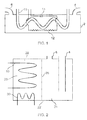
- FIG. 1 schematically illustrates a first embodiment of the present invention which comprises a vessel, generally designated 2, having an inlet 4 arranged to receive grey water from a bath or shower and an outlet 6 arranged to deliver grey water to a drain.
- the shape of the vessel is not particularly important, but it may advantageously be relatively long compared to its height or width such that it could be installed in the space beneath the bath, between floor joists, or under a kitchen cupboard.
- the vessel may be made of any suitable material, including metals or plastics. In use, the vessel fills with grey water such that this embodiment always contains a volume of grey water from the bath or shower.
- the inlet pipe 4, the void in the interior of the vessel 2 and the outlet pipe 6 form a first liquid flow path.
- a second liquid flow path for, for example, mains water is provided by a pipe 10 which passes through the majority of the vessel 2.
- the pipe may be provided with fins, but more easily is simply formed into a meandering path or a spiral or coil.
- the pipe 10 can be placed in series connection between a water main and a boiler or some other domestic appliance such as a washing machine or a dishwasher.
- Legionella can be controlled by heating to above 50°C, and preferably to above 60°C, so as to kill the bacteria.
- this heating means in this example in the form of an electrically powered heater 12 is disposed within the heat recovery apparatus such that it can be energised to heat the water in the pipe 10, and advantageously also the grey water within the vessel 2 thereby preventing risk of disease.
- the heater 12 may be energised periodically by a time clock or a controller and may include an inline thermostat 14 to interrupt the power supply to the heater 12 once the temperature of the water in vessel 2 exceeds a predetermined upper limit, for example 65°, in order to prevent excessive waste of energy or risk of boiling.
- FIG 2 shows a variation on the theme in Figure 1 where a heat storage reservoir 20, in this instance in the form of a closed vessel 20 filled with a suitable liquid, such as water, is provided within a vessel 22 and the first liquid flow path from the inlet 4 to the outlet 6 is via a chamber 24.
- a cold water main 10 meanders through the reservoir 20 so as to pick up heat therefrom and a further pipe 30 allows heat from the warmed fluid within the pipe 30 to heat the water 28 in the reservoir 20 to above 50 or 60°C, and in so doing also warms the water within the pipe 10 to that temperature.
- the pipe 30 may, for example, be part of a dedicated warming circuit or may be driven from the primary circuit of a boiler.
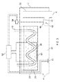
- Figure 3 shows a further variation which in many ways is similar to Figure 2 as a reservoir 20 containing water 28 is provided and the secondary liquid flow path 10 meanders through the reservoir 20 so as to pick heat up from the water 28.
- the arrangement in Figure 3 alleviates this problem because the inlet 4 and the outlet 6 are formed towards the bottom of the vessel 2 and, in addition, a restricted flow orifice, or several orifices are formed near the outlet 6 such that in the absence of water inflow above a predetermined rate the grey water region 40 of the vessel 2 tends to drain.
- a thermostatically controlled valve 42 for example in the form of a movable closure 44 co-operating with an orifice 46 may be provided such that if the water passing through the region 40 is too cold then it is ducted directly towards the outlet 6 and is not allowed to collect in the region 40. This in turn prevents cold grey water from coming in contact with a heat exchange wall 26 of the reservoir 20.
- the temperature of the water could be determined by a mechanically operated temperature sensing valve, or as shown in Figure 3 may be determined by an electronic temperature sensing element 50 which is connected to a controller 52 which in turn controls an electric actuator 54, such as a stepper motor or a solenoid which is mechanically connected to the valve 42 so as to open and close it.
- the controller 52 actuates the actuator 54 so as to close the valve 42 thereby forcing the warm grey water to collect within the vessel 2 until such time as its level is sufficiently high to reach the top of an overflow pipe 56 which is in connection with the drain 6. This arrangement ensures that any failure of the controller 52 the temperature sensor 50 or the actuator 54 will not prevent the passage of grey water towards a drain.
- This arrangement not only has the advantage that cold water does not come in contact with the reservoir 20, thereby depleting heat from it unnecessarily, but it also means that only the volume of water 28 in the reservoir 20 and in the section of the pipe 10 that passes through the reservoir 20 needs to be warmed by the heater in order to kill the Legionella bacteria. Further temperature sensors may be provided in the reservoir 20 in order to determine when it has been heated sufficiently, for example under the control of an electrical heater 60.
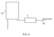
- the heat exchange apparatus as shown in Figures 1, 2 or 3 may be placed in serious connection between the water main 70 and an appliance 72 as shown in Figure 4 .
- the appliance 72 might be a washing machine or a dishwasher or alternatively could be a boiler for providing domestic hot water.
Landscapes
- Engineering & Computer Science (AREA)
- Physics & Mathematics (AREA)
- Thermal Sciences (AREA)
- Mechanical Engineering (AREA)
- General Engineering & Computer Science (AREA)
- Combustion & Propulsion (AREA)
- Chemical & Material Sciences (AREA)
- Health & Medical Sciences (AREA)
- Life Sciences & Earth Sciences (AREA)
- Hydrology & Water Resources (AREA)
- Public Health (AREA)
- Water Supply & Treatment (AREA)
- Environmental & Geological Engineering (AREA)
- Heat-Pump Type And Storage Water Heaters (AREA)
Applications Claiming Priority (1)
| Application Number | Priority Date | Filing Date | Title |
|---|---|---|---|
| GB1000189A GB2468002B (en) | 2010-01-07 | 2010-01-07 | Heat recovery apparatus |
Publications (2)
| Publication Number | Publication Date |
|---|---|
| EP2351968A2 true EP2351968A2 (de) | 2011-08-03 |
| EP2351968A3 EP2351968A3 (de) | 2015-07-15 |
Family
ID=41819027
Family Applications (1)
| Application Number | Title | Priority Date | Filing Date |
|---|---|---|---|
| EP10193506.2A Withdrawn EP2351968A3 (de) | 2010-01-07 | 2010-12-02 | Wärmerückgewinnungsvorrichtung |
Country Status (3)
| Country | Link |
|---|---|
| US (1) | US20110162824A1 (de) |
| EP (1) | EP2351968A3 (de) |
| GB (1) | GB2468002B (de) |
Cited By (1)
| Publication number | Priority date | Publication date | Assignee | Title |
|---|---|---|---|---|
| CN106391417A (zh) * | 2016-11-08 | 2017-02-15 | 无锡市全顺机械制造有限公司 | 用于植绒室的散热器结构 |
Families Citing this family (8)
| Publication number | Priority date | Publication date | Assignee | Title |
|---|---|---|---|---|
| US20120298328A1 (en) * | 2011-04-27 | 2012-11-29 | Hidden Fuels, Llc | Methods and apparatus for transferring thermal energy |
| CN103104009B (zh) * | 2013-02-02 | 2015-01-21 | 中铁建设集团有限公司 | 一种超高层建筑水势能发电和热回收系统 |
| US12305377B2 (en) | 2018-02-27 | 2025-05-20 | University Of Virginia Patent Foundation | System and method for disinfection of a plumbing system associated with liquid waste |
| CN108980957A (zh) * | 2018-07-20 | 2018-12-11 | 南京骁科信息科技有限公司 | 新能源热能转换供热装置 |
| CN108980956A (zh) * | 2018-07-20 | 2018-12-11 | 南京骁科信息科技有限公司 | 一种新能源热能转换供热装置 |
| WO2022253930A1 (en) * | 2021-06-04 | 2022-12-08 | Ideal Standard International Nv | Clinical wash station |
| US12065810B2 (en) * | 2021-11-04 | 2024-08-20 | Haier Us Appliance Solutions, Inc. | Systems and methods for automatically performing a flush operation for a water supply |
| CA222016S (en) | 2023-06-08 | 2024-09-06 | Ipex Tech Inc | Heat exchange device |
Citations (1)
| Publication number | Priority date | Publication date | Assignee | Title |
|---|---|---|---|---|
| GB2461077A (en) | 2008-06-19 | 2009-12-23 | Zenex Technologies Ltd | Heating system comprising a thermal store |
Family Cites Families (11)
| Publication number | Priority date | Publication date | Assignee | Title |
|---|---|---|---|---|
| DE2304537B2 (de) * | 1973-01-31 | 1975-08-14 | Rheinisch-Westfaelisches Elektrizitaetswerk Ag, 4300 Essen | Wärmerückgewinnungsanlage |
| US4304292A (en) * | 1979-07-16 | 1981-12-08 | Cardone Jeremiah V | Shower |
| GB2079908B (en) * | 1980-06-23 | 1984-05-16 | Metal Spinners Ireland Ltd | Steam and water boiler |
| DE8600554U1 (de) * | 1986-01-11 | 1987-05-07 | Brieda, Volker, Dipl.-Ing., 3500 Kassel | Vorrichtung zur Rückgewinnung von Abwärme aus Duschbädern, Duschkabinen und ähnlichen Einrichtungen |
| GB2226116B (en) * | 1988-12-16 | 1992-08-05 | Chun Wah Kwok | Water container |
| DE4126791C2 (de) * | 1991-08-14 | 1993-10-21 | Klaus Seib | Einrichtung zur Wärmerückgewinnung aus warmem Haushaltsabwasser |
| DE29615555U1 (de) * | 1996-09-06 | 1996-10-31 | Schnells, Rainer, 42799 Leichlingen | Duschsystem |
| US6367703B1 (en) * | 2000-04-07 | 2002-04-09 | Christopher G. Morosas | Heat recovery system |
| DE202006010615U1 (de) * | 2005-09-26 | 2006-10-26 | Dbk David + Baader Gmbh | Tanksystem mit einem Haupttank und einer Abschmelzvorrichtung mit Schmelztank |
| AU2007216714B2 (en) * | 2006-09-13 | 2012-05-17 | Inform Energy Pty Ltd | Fluid supply system |
| US7913331B2 (en) * | 2008-03-09 | 2011-03-29 | Hartman Reinoud Jacob | Integrated domestic utility system |
-
2010
- 2010-01-07 GB GB1000189A patent/GB2468002B/en not_active Expired - Fee Related
- 2010-12-02 EP EP10193506.2A patent/EP2351968A3/de not_active Withdrawn
- 2010-12-13 US US12/966,532 patent/US20110162824A1/en not_active Abandoned
Patent Citations (1)
| Publication number | Priority date | Publication date | Assignee | Title |
|---|---|---|---|---|
| GB2461077A (en) | 2008-06-19 | 2009-12-23 | Zenex Technologies Ltd | Heating system comprising a thermal store |
Cited By (1)
| Publication number | Priority date | Publication date | Assignee | Title |
|---|---|---|---|---|
| CN106391417A (zh) * | 2016-11-08 | 2017-02-15 | 无锡市全顺机械制造有限公司 | 用于植绒室的散热器结构 |
Also Published As
| Publication number | Publication date |
|---|---|
| GB2468002B (en) | 2011-12-07 |
| US20110162824A1 (en) | 2011-07-07 |
| EP2351968A3 (de) | 2015-07-15 |
| GB201000189D0 (en) | 2010-02-24 |
| GB2468002A (en) | 2010-08-25 |
Similar Documents
| Publication | Publication Date | Title |
|---|---|---|
| EP2351968A2 (de) | Wärmerückgewinnungsvorrichtung | |
| CN101677719B (zh) | 用于油炸锅的自动填充装置 | |
| HRP20090099T5 (hr) | Naprava za proizvodnju napitaka na bazi termoblokova s komorama za kuhanje | |
| US20120237191A1 (en) | Electric water heating element | |
| CA2965534C (en) | Steam cooking oven with temperature sensor in vent stack, and method of controlling steam production thereof | |
| JP5441440B2 (ja) | 温水器 | |
| US11988397B2 (en) | Hot water supply control system and method for domestic electric water heaters to prevent the risk of bacterial transfer | |
| WO2011089434A2 (en) | Liquid heating apparatus | |
| CN102778021A (zh) | 即热沸腾式开水器装置 | |
| KR20120020190A (ko) | 소형화된 진공 전기 온수 보일러 | |
| CN202636659U (zh) | 液体加热器具 | |
| JP5385181B2 (ja) | 貯湯式給湯装置 | |
| KR20100091646A (ko) | 농업용 전기 가온기 | |
| JP5965731B2 (ja) | 貯湯タンクの沸き上げ方法及び貯湯式給湯機 | |
| US10928097B2 (en) | System and method for generating heated water and distilled water | |
| EP3187786A1 (de) | Kochofen mit wärmerückgewinnungssystem | |
| JP2010078189A (ja) | 給湯装置 | |
| JP3647916B2 (ja) | 電気温水器 | |
| CN207270260U (zh) | 带回水管的即饮电热水瓶 | |
| EP3280304B1 (de) | Heizvorrichtung | |
| JPH0373792B2 (de) | ||
| CN208598163U (zh) | 一种饮水机 | |
| EP1939540A2 (de) | Heizsystem | |
| JP5106567B2 (ja) | 貯湯式給湯システム | |
| AU2009233609A1 (en) | Control assembly |
Legal Events
| Date | Code | Title | Description |
|---|---|---|---|
| PUAI | Public reference made under article 153(3) epc to a published international application that has entered the european phase |
Free format text: ORIGINAL CODE: 0009012 |
|
| AK | Designated contracting states |
Kind code of ref document: A2 Designated state(s): AL AT BE BG CH CY CZ DE DK EE ES FI FR GB GR HR HU IE IS IT LI LT LU LV MC MK MT NL NO PL PT RO RS SE SI SK SM TR |
|
| AX | Request for extension of the european patent |
Extension state: BA ME |
|
| PUAL | Search report despatched |
Free format text: ORIGINAL CODE: 0009013 |
|
| AK | Designated contracting states |
Kind code of ref document: A3 Designated state(s): AL AT BE BG CH CY CZ DE DK EE ES FI FR GB GR HR HU IE IS IT LI LT LU LV MC MK MT NL NO PL PT RO RS SE SI SK SM TR |
|
| AX | Request for extension of the european patent |
Extension state: BA ME |
|
| RIC1 | Information provided on ipc code assigned before grant |
Ipc: F28D 1/02 20060101ALI20150608BHEP Ipc: E03C 1/00 20060101ALI20150608BHEP Ipc: F28D 7/00 20060101ALI20150608BHEP Ipc: F24D 11/00 20060101AFI20150608BHEP Ipc: F24D 17/00 20060101ALI20150608BHEP Ipc: F28D 7/10 20060101ALI20150608BHEP |
|
| STAA | Information on the status of an ep patent application or granted ep patent |
Free format text: STATUS: THE APPLICATION IS DEEMED TO BE WITHDRAWN |
|
| 18D | Application deemed to be withdrawn |
Effective date: 20160116 |