EP2349871B1 - Device and assembly for supporting a pair of windscreen wipers, and corresponding packaging and method for mounting same - Google Patents
Device and assembly for supporting a pair of windscreen wipers, and corresponding packaging and method for mounting same Download PDFInfo
- Publication number
- EP2349871B1 EP2349871B1 EP09736824.5A EP09736824A EP2349871B1 EP 2349871 B1 EP2349871 B1 EP 2349871B1 EP 09736824 A EP09736824 A EP 09736824A EP 2349871 B1 EP2349871 B1 EP 2349871B1
- Authority
- EP
- European Patent Office
- Prior art keywords
- wipers
- pair
- supporting
- assembly
- windscreen
- Prior art date
- Legal status (The legal status is an assumption and is not a legal conclusion. Google has not performed a legal analysis and makes no representation as to the accuracy of the status listed.)
- Active
Links
- 238000004806 packaging method and process Methods 0.000 title claims description 6
- 238000000034 method Methods 0.000 title claims description 5
- 238000001125 extrusion Methods 0.000 claims description 6
- 238000002347 injection Methods 0.000 claims description 6
- 239000007924 injection Substances 0.000 claims description 6
- 238000000926 separation method Methods 0.000 claims 2
- 244000007853 Sarothamnus scoparius Species 0.000 description 9
- 239000011521 glass Substances 0.000 description 7
- 238000004519 manufacturing process Methods 0.000 description 5
- 239000000243 solution Substances 0.000 description 5
- 239000013256 coordination polymer Substances 0.000 description 4
- 230000003750 conditioning effect Effects 0.000 description 3
- 238000003780 insertion Methods 0.000 description 3
- 230000037431 insertion Effects 0.000 description 3
- 238000012423 maintenance Methods 0.000 description 3
- 230000000295 complement effect Effects 0.000 description 2
- 239000000463 material Substances 0.000 description 2
- 125000006850 spacer group Chemical group 0.000 description 2
- 230000008878 coupling Effects 0.000 description 1
- 238000010168 coupling process Methods 0.000 description 1
- 238000005859 coupling reaction Methods 0.000 description 1
- 238000013461 design Methods 0.000 description 1
- 230000001627 detrimental effect Effects 0.000 description 1
- 238000009472 formulation Methods 0.000 description 1
- 238000009432 framing Methods 0.000 description 1
- 239000000203 mixture Substances 0.000 description 1
- 238000012986 modification Methods 0.000 description 1
- 230000004048 modification Effects 0.000 description 1
- 238000012856 packing Methods 0.000 description 1
Images

Classifications
-
- B—PERFORMING OPERATIONS; TRANSPORTING
- B65—CONVEYING; PACKING; STORING; HANDLING THIN OR FILAMENTARY MATERIAL
- B65D—CONTAINERS FOR STORAGE OR TRANSPORT OF ARTICLES OR MATERIALS, e.g. BAGS, BARRELS, BOTTLES, BOXES, CANS, CARTONS, CRATES, DRUMS, JARS, TANKS, HOPPERS, FORWARDING CONTAINERS; ACCESSORIES, CLOSURES, OR FITTINGS THEREFOR; PACKAGING ELEMENTS; PACKAGES
- B65D85/00—Containers, packaging elements or packages, specially adapted for particular articles or materials
- B65D85/54—Containers, packaging elements or packages, specially adapted for particular articles or materials for articles of special shape not otherwise provided for
-
- B—PERFORMING OPERATIONS; TRANSPORTING
- B60—VEHICLES IN GENERAL
- B60S—SERVICING, CLEANING, REPAIRING, SUPPORTING, LIFTING, OR MANOEUVRING OF VEHICLES, NOT OTHERWISE PROVIDED FOR
- B60S1/00—Cleaning of vehicles
- B60S1/02—Cleaning windscreens, windows or optical devices
- B60S1/04—Wipers or the like, e.g. scrapers
- B60S1/32—Wipers or the like, e.g. scrapers characterised by constructional features of wiper blade arms or blades
- B60S1/38—Wiper blades
-
- B—PERFORMING OPERATIONS; TRANSPORTING
- B65—CONVEYING; PACKING; STORING; HANDLING THIN OR FILAMENTARY MATERIAL
- B65D—CONTAINERS FOR STORAGE OR TRANSPORT OF ARTICLES OR MATERIALS, e.g. BAGS, BARRELS, BOTTLES, BOXES, CANS, CARTONS, CRATES, DRUMS, JARS, TANKS, HOPPERS, FORWARDING CONTAINERS; ACCESSORIES, CLOSURES, OR FITTINGS THEREFOR; PACKAGING ELEMENTS; PACKAGES
- B65D85/00—Containers, packaging elements or packages, specially adapted for particular articles or materials
- B65D85/68—Containers, packaging elements or packages, specially adapted for particular articles or materials for machines, engines or vehicles in assembled or dismantled form
-
- B—PERFORMING OPERATIONS; TRANSPORTING
- B60—VEHICLES IN GENERAL
- B60S—SERVICING, CLEANING, REPAIRING, SUPPORTING, LIFTING, OR MANOEUVRING OF VEHICLES, NOT OTHERWISE PROVIDED FOR
- B60S1/00—Cleaning of vehicles
- B60S1/02—Cleaning windscreens, windows or optical devices
- B60S1/04—Wipers or the like, e.g. scrapers
- B60S1/32—Wipers or the like, e.g. scrapers characterised by constructional features of wiper blade arms or blades
- B60S1/38—Wiper blades
- B60S2001/3843—Wiper blades equipped with removable cover or protective elements
-
- B—PERFORMING OPERATIONS; TRANSPORTING
- B60—VEHICLES IN GENERAL
- B60S—SERVICING, CLEANING, REPAIRING, SUPPORTING, LIFTING, OR MANOEUVRING OF VEHICLES, NOT OTHERWISE PROVIDED FOR
- B60S1/00—Cleaning of vehicles
- B60S1/02—Cleaning windscreens, windows or optical devices
- B60S1/04—Wipers or the like, e.g. scrapers
- B60S1/32—Wipers or the like, e.g. scrapers characterised by constructional features of wiper blade arms or blades
- B60S1/38—Wiper blades
- B60S2001/3898—Wiper blades method for manufacturing wiper blades
-
- B—PERFORMING OPERATIONS; TRANSPORTING
- B65—CONVEYING; PACKING; STORING; HANDLING THIN OR FILAMENTARY MATERIAL
- B65D—CONTAINERS FOR STORAGE OR TRANSPORT OF ARTICLES OR MATERIALS, e.g. BAGS, BARRELS, BOTTLES, BOXES, CANS, CARTONS, CRATES, DRUMS, JARS, TANKS, HOPPERS, FORWARDING CONTAINERS; ACCESSORIES, CLOSURES, OR FITTINGS THEREFOR; PACKAGING ELEMENTS; PACKAGES
- B65D2585/00—Containers, packaging elements or packages specially adapted for particular articles or materials
- B65D2585/68—Containers, packaging elements or packages specially adapted for particular articles or materials for machines, engines, or vehicles in assembled or dismantled form
- B65D2585/6802—Containers, packaging elements or packages specially adapted for particular articles or materials for machines, engines, or vehicles in assembled or dismantled form specific machines, engines or vehicles
- B65D2585/6875—Containers, packaging elements or packages specially adapted for particular articles or materials for machines, engines, or vehicles in assembled or dismantled form specific machines, engines or vehicles engines, motors, machines and vehicle parts
- B65D2585/6882—Containers, packaging elements or packages specially adapted for particular articles or materials for machines, engines, or vehicles in assembled or dismantled form specific machines, engines or vehicles engines, motors, machines and vehicle parts vehicle parts
- B65D2585/6885—Containers, packaging elements or packages specially adapted for particular articles or materials for machines, engines, or vehicles in assembled or dismantled form specific machines, engines or vehicles engines, motors, machines and vehicle parts vehicle parts wiper blades
Definitions
- the present invention relates to a device for holding a pair of windscreen wiper blades each comprising a structural element and a wiper blade whose free end is intended to be in contact with a glass surface to be wiped.
- the invention also relates to a holding assembly comprising a plurality of holding devices, and a packaging and a corresponding mounting method.
- the device or the holding assembly is for example intended to be used for marketing, in store shelves, a kit for replacing a pair of wiper blades of a vehicle, or for the purpose of transporting a pair of windscreen wiper blades from the place of production to the place of packing or to the place of assembly on a motor vehicle.
- the pairs of conventional windscreen wiper blades are generally packaged in a blister or in a cardboard package, for example a box, of generally slender and linear shape. Indeed, the shape of these brushes allows simple packaging, linear and whose size is not necessarily more important than the dimensions of the pair of wiper blades itself.
- a first solution to allow conditioning of a pair of windscreen wiper blades, in particular of the flat-blade type, is proposed in the US patent published under the number US 6,779,661 .
- This document describes, in particular with reference to FIGS. 12 to 15, a longitudinal shaped packaging support in which are inserted longitudinally, at one end of the support, two wiper blades.
- the support has either notches or pins in which complementary shapes provided on the wiper blades are slid.
- the conditioning support is not longitudinal in shape, but consists of a plurality of holding devices in which are inserted longitudinally the two windscreen wiper blades.
- the invention thus relates more precisely to a holding device comprising means for fastening the respective structural elements of the two brushes by elastic coupling in a position in which the wiping blades of the two brushes are oriented towards the inside of the holding device. , the respective longitudinal plane of symmetry of these blades remaining substantially parallel.
- the assembly consisting of the holding device and the pair of windscreen wiper blades mounted on this device has a certain size.
- the invention therefore proposes to find a packaging solution applicable to flat-blade windscreen wiper blades but also to other types of wiper blade pairs, which not only have the advantages of holding device using a fastening system by elastic casing but also a small footprint.
- the invention relates to a device for holding a pair of windscreen wiper blades according to claim 1.
- the size is reduced.
- the slight slight loss in width of a package containing the mounted assembly consisting of the holding device and the two brushes is largely offset by the gain in height due to the approximation of the two brushes.
- a holding device which is not part of the invention, comprises a section comprising two channels in "V" inverted in relation to each other, having a common wall and inside which are intended to be respectively housed the two wiper blades of the pair of wiper blades in the nested position thereof.
- a holding device comprises a section comprising two channels which are inverted relative to one another, in the general shape of a "U" whose base is common, the section of this base being in a slot extending from both sides of said median plane of the holding device, and inside which are intended to be housed respectively the two wiper blades of the pair of wiper blades in the nested position thereof.
- the means for fixing by elastic casing of the respective structural elements of the two brushes are arranged in pairs at the open ends of each channel.
- the resiliently fitting means for fastening the respective structural elements of the two brushes are associated with disengagement means comprising a spacer lug of the fastening means.
- a holding device according to the invention can be obtained by extrusion or by plastic injection.
- a holding device may comprise a rail extending over a major part of the length of the pair of windscreen wiper blades, the rail comprising several distinct zones each comprising their own means of fastening the pair of windscreen wiper blades by elastic casing.
- length of the pair of windscreen wiper blades means the length over which the two windscreen wiper blades are side by side. In particular, if one broom is smaller than the other and does not protrude beyond one end or the other of the large broom, it is the length of the small broom. By “most of the length” is meant at least half that length.
- a holding assembly according to the invention may comprise at least three holding devices, two being close to the ends of the brushes of the pair and one being close to a central zone in which brush connectors are arranged at the ends of the brushes of the pair. wiper drive arm.
- a holding assembly according to the invention may comprise at least four holding devices, two of them being close to the central zone and arranged on either side of the brushes connectors to the drive arms. wiper.
- each holding device of the holding assembly further comprises at least one gripping protrusion of a guide arm, to ensure alignment of the holding devices in fixing situation of the pair of brushes. windscreen wipers.
- the invention also relates to a package for a pair of windscreen wiper blades, comprising a holding device or a holding assembly as defined above.
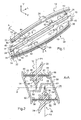
- the figure 1 is a perspective view of a holding device according to a first embodiment of the invention, designated by the general reference 10.
- the longitudinal, vertical and transverse directions indicated in this figure by the fixed trihedron (L, V, T) with respect to the holding device 10 will be adopted without limitation.
- the longitudinal direction L, line of flight of the cavalry perspective corresponds to the main direction of the holding device 10 which is, in this first example, in the form of a rail.
- the transverse direction T corresponds to the horizontal direction of the figure 1 .
- the vertical direction V corresponds to the vertical direction of the figure 1 .
- the holding device 10 is adapted to receive a pair of windscreen wiper blades, for example of the flat blade type. It is advantageously constituted by a rigid piece, for example a plastic material, obtained for example by extrusion or plastic injection.
- a first wiper blade 12 ready to be mounted on the holding device 10 is shown above it, vertically above a first channel 14 arranged inside the holding device and whose the longitudinal opening is intended to receive a wiper blade 16 of the first blade 12.
- This first flat blade 12 is of curved shape, to adhere to a glazed surface such as a windshield of a motor vehicle, and extends longitudinally in the direction L.
- Its wiper blade 16 is carried by a structural element 18 itself comprising a support frame 20 and two lateral vertebrae 22 fixed to this support frame 20.
- the support frame 20 by a particular aerodynamic shape, can fill a function of spoiler (of the English "spoiler") to improve the adhesion of the blade 12 on the glass surface. It further comprises two lateral notches extending longitudinally to receive the two lateral vertebrae 22.
- the support frame 20 may be tubular and adapted to receive a single inner vertebra.
- the first wiper blade 12 also has, disposed approximately in the middle, a connector 24 for connection to a first wiper drive arm (not shown) generally connected to a motor.
- a second wiper blade 26 ready to be mounted on the holding device 10 is shown below it, vertically above a second channel 28 arranged inside the holding device and whose the longitudinal opening, intended to receive a wiper blade 30 of the second blade 26, is oriented in a direction opposite to that of the first channel 14.
- this second blade 26 of flat-blade type is of curved shape and extends longitudinally in the direction L. Its wiper blade 30 is carried by a structural element 32 itself comprising a frame of support 34 and two lateral vertebrae 36 fixed to this support mount 34. The second wiper blade 26 also comprises, arranged approximately in the middle, a connector 38 intended to allow its connection to a second drive arm of wiper (not shown).
- one of the two is a driver side wiper blade (CC), the other being adapted for the passenger side (CP) .
- the brushes CP and CC are not necessarily identical. In particular, they are not necessarily the same length: in general, the DC broom is longer than the CP broom, the glass surface to be cleaned on the driver's side often to be larger than that on the passenger side.
- this rail extends over a major part of the length of the pair of wiper blades, that is to say over at least half the length of the smallest blade, the broom CP.
- the rail may comprise a plurality of zones Z1, Z2, Z3 and Z4 each comprising positioning means or fixing means to concretely hold the two brushes flat.
- These positioning and fixing means are for example arranged in pairs on the side walls of the channels 14 and 28 on the side of their respective openings intended to receive the brushes 12 and 26.
- the zone Z1 is located at the front end and the zone Z4 at the rear end of the holding device 10. In the embodiment of the figure 1 these two zones comprise the positioning means.
- Z2 and Z3 areas are located in a central region of the holding device 10 for receiving the connectors 24, 38 of the two brushes. They are more precisely located on both sides of the connectors longitudinally when the brushes are mounted in the holding device 10. These two zones comprise the fixing means.
- the positioning means arranged at the front ends Z1 and rear Z2 of the holding device 10 and represented by the general reference 40, are for example directly arranged in the holding device 10 by extrusion or plastic injection. At least locally, the side walls of the channels 14 and 28 extend, on the one hand, vertically towards the outside of the holding device 10 and, on the other hand, horizontally towards the inside of the holding device 10. Horizon extensions make it possible to provide a bearing surface for the lateral vertebrae 22, 36 of the first and second brushes so as to lock the brushes vertically by limiting their engagement inside the holding device 10. The vertical extensions allow lateral framing the lateral vertebrae 22, 36 of the first and second brushes so as to lock the brushes laterally. In this embodiment, the positioning means 40 do not ensure the attachment of the wiper blades strictly speaking but contribute to their guidance and their good positioning in the holding device 10. They indeed avoid torsion and the twisting of the brushes ensuring them a stable support.
- the fixing means are for example also directly arranged in the holding device 10 by extrusion or plastic injection.
- the side walls of the channels 14 and 28 extend, on the one hand, vertically towards the outside of the holding device 10 and, on the other hand, horizontally towards the inside of the holding device 10.
- horizontal extensions provide a bearing surface to the lateral vertebrae 22, 36 of the first and second brushes.
- the vertical extensions can laterally frame the lateral vertebrae 22, 36 of the first and second brushes so as to laterally block the brushes.
- the vertical extensions of the fastening means 42 comprise clips 44 integral with the holding device 10. The shape and the number of the clips 44 varies as necessary, which makes it possible to obtain efficient and stable fastening of the pair of brushes 12 and 26 because the fastening means 42 act directly on a structural element of the brushes, namely their lateral vertebrae.
- the user To mount the first wiper blade 12 in the holding device 10, the user exerts a pressure in the direction of the arrow F1 on the first wiper blade 12 facing the positioning means 40 and fixing 42 distributed on the first channel 14 of the holding device 10. The user thus acts against the fastening means 42 by elastically fitting the lateral vertebrae of the first wiper blade 12. The latter is then maintained flat by the clips 44, guided at the positioning means and free at its ends.
- the user exerts a pressure in the direction of the arrow F2 on the second wiper blade 26 facing the positioning means 40 and fixing 42 distributed on the second channel 28 of the holding device 10.
- the user thus acts against the fastening means 42 by resiliently fitting the lateral vertebrae of the second wiper blade 26.
- the latter is then maintained flat by the clips 44, guided at the positioning means and free at its ends.
- the figure 2 illustrates the assembly consisting of the holding device 10 and the two brushes 12, 26 mounted thereon in section AA, that is to say in a plane orthogonal to the longitudinal direction L, at the fastening means 42 located in zone Z3.
- the wiper blade 16, carried by the structural element 18 of the first blade 12 is, in this example, integral with the support frame 20 and connected thereto via a narrowing 46 over the entire length of this mount.
- This narrowing 46 allows the wiper blade 16 to pivot relative to a longitudinal axis at each change of direction when the first blade 12 is actuated by the arm of the corresponding wiper against the glass surface.
- the wiper blade 16 has a first wide end 48 extending longitudinally adjacent the narrowing 46 and a second end 50, thin and free, intended to be in contact with the glazed surface to be wiped.
- the wiper blade 16 has a longitudinal plane of symmetry P1.
- the wiper blade 16 is completely lodge inside the first channel 14, its longitudinal plane of symmetry P1 being maintained substantially vertical, or more precisely substantially parallel to the directions L, V.
- the wiper blade 30, carried by the structural member 32 of the second blade 26 is also integral with the support mount 34 and connected thereto via a narrowing 52 along the entire length of this frame. It also has a first wide end 54 extending longitudinally adjacent the narrowing 52 and a second end 56, thin and free, intended to be in contact with the glass surface to be wiped.
- the wiper blade 30 has a longitudinal plane of symmetry P2.
- the wiper blade 30 In the mounted position on the holding device 10, when the lateral vertebrae 36 of the second blade 26 are held between the horizontal extensions, the vertical extensions and the clips disposed on the side walls of the second channel 28, the wiper blade 30 is completely lodge inside the second channel 28, its longitudinal plane of symmetry P2 being maintained substantially vertical, or more precisely substantially parallel to the directions L, V, that is to say substantially parallel to the plane P1.
- the illustration of the figure 2 highlights a particular section of the holding device 10 according to a first variant of the invention.
- the holding device 10 has a section in which two parallel outer walls 58, 60 extend longitudinally on either side of a median plane P of the device, this median plane being horizontal, that is to say parallel to the directions L, T.
- These two outer walls 58 and 60 form the outer walls of the two channels 14 and 28. They are interconnected by a base 62, common to the two channels 14 and 28, s' extending longitudinally in the vicinity of the median plane P.
- the two channels 14 and 28 are inverted relative to each other and in the general form of "U" whose base 62 is common.
- the fixing means 42 of the holding device 10 comprise, as indicated previously, horizontal extensions 64 of the lateral walls 58, 60 extending towards the inside of the holding device 10 and vertical extensions 66 of the side walls 58, 60 s extending outwardly of the holding device 10.
- vertical extensions 66 are provided with clips 44 to ensure, in cooperation with the horizontal extensions 64, the elastic fastening function of the lateral vertebrae 22, 36 of the wiper blades.
- the fixing means are thus arranged in pairs at the open ends of each channel 14, 28: an upper fixing pair located above the median plane P for holding the first blade 12 and a lower fixing pair located below the plane median P for maintaining the second blade 26.
- the offset position of the wiper blades due to the inclination of the outer walls 58 and 60 has a first advantage. It prevents the wiper blades 16 and 30 from touching in the mounted position of the brushes, even if they had to maintain a certain curvature at the ends. But above all, this offset position combined with the previously described form of the base 62 of the holding device 10 makes it possible to reduce the distance between the two brushes by bringing the upper and lower binding pairs closer together, so that the blades can overlap partially. laterally without touching each other, or at least each reach the median plane P. This results in a saving of space of the assembly consisting of the pair of windscreen wiper blades and the holding device, ie a space saving taken by a package comprising this set.
- the figure 3 is a perspective view of a holding assembly comprising a plurality of holding devices 10 1 , 10 2 , 10 3 , 10 4 , according to a second embodiment of the invention.
- the holding assembly is not designed in the form of a single device 10 in the form of a rail that locally comprises fastening means or positioning means, but in the form of a plurality of devices. independent and can be identical. They are all provided with fastening means such as those described above. They include in particular each pair of clips 44 for attachment by elastic interlocking with each blade of the pair.
- the holding assembly is not designed in the form of a single rail but a plurality of independent devices is independent of the invention as described above in its first aspect and could equally well to apply advantageously to maintenance sets of the state of the art, such as those envisaged in the document FR 2 900 133 , to modify them so as to make them less expensive to manufacture.
- the figure 3 represents four independent devices.
- the devices 10 1 and 10 4 are arranged opposite the ends of the windscreen wiper blades 12 and 26 while the devices 10 2 and 10 3 are arranged in a central region close to the connectors 24 and 38 of these brushes, more precisely on both sides of the connectors longitudinally.
- two holding devices are required at least: for example the devices 10 2 and 10 3 (on either side of the connectors), or the devices 10 1 and 10 3 or 10 2 and 10 4 (the one at one end, the other in the vicinity of the connectors on the side of the other end), or the devices 10 1 and 10 4 (one at each end).
- three holding devices can be used: one at each end and one in the vicinity of the connectors 24 and 38.
- the user To mount the first wiper blade 12 in the holding assembly, the user has the independent holding devices 10 1 , 10 2 , 10 3 , 10 4 facing the desired areas on the first blade 12 then exerts a pressure in the direction of the arrow F1 on this first wiper blade 12. The user thus acts against the attachment means 42 by resiliently fitting the lateral vertebrae of the first wiper blade. 12. Then to mount the second wiper blade 26 in the holding assembly, the user exerts pressure in the direction of the arrow F2 on the second wiper blade 26 opposite the independent holding devices 10 1 , 10 2 , 10 3 , 10 4 . The user thus acts against the fixing means 42 by elastically fitting the lateral vertebrae of the second wiper blade 26.
- the figure 5 illustrates a particular section of the holding device 10 according to section AA, or a section of each independent device 10 1 , 10 2 , 10 3 , 10 4 of the holding assembly, according to a second variant of the invention, which does not form part of the invention.
- the holding device 10 has a section in which the two parallel outer walls 58, 60 extend longitudinally from on both sides of the median plane P of the device.
- the inner wall base 62 is flat and connects the outer walls diagonally to form the two inverted “V" channels 14 and 28.
- the first channel 14 thus comprises two walls in "V", one of which is the outer wall 60 and the other the inner wall 62, between which is housed the wiper blade 16 of the first broom 12.
- the second channel 28 comprises two walls in "V", one of which is the outer wall 58 and the other the inner wall 62, between which is housed the wiper blade 30 of the second blade 26.
- the fastening means 42 comprise horizontal extensions 64 located at the open ends of the walls of the channels 14 and 28 and here taking the form of cubits at the open ends of the side walls 58 and 60. They also comprise extensions. vertical members 66 located at the open ends of the walls of the channels 14 and 28 and provided with clips 44 for fixing the lateral vertebrae 22, 36 of the pair of brushes.
- this spacer can itself take the form of an additional extension of at least a portion of the vertical extensions 66 .
- each of these devices may comprise projections 70 for gripping a linear guide arm 72, to ensure alignment. independent devices when fixing the first wiper blade 12.
- This linear guide arm 72 is for example of cylindrical shape.
- the gripping projections 70 are, for example, in the form of a gripper formed integrally with the holding device 10 1 , 10 2 , 10 3 or 10 4 and extending from one of the external faces of its walls, which can be deform slightly and thus grasp the linear guide arm 72 by elastic casing.
- the embodiments described above are particularly suitable for flat-blade type brushes in which lateral vertebrae give the brooms a curved shape.
- the fastening means are adapted to hold the brushes with their lateral vertebrae.
- the fastening means can be adapted, especially as suggested in the document FR 2 900 133 , to maintain the brushes with another structural element such as their support frame for example.
- the figure 6 has in particular a section along the axis AA of the device of the figure 1 in which is mounted a pair of flat-blade windscreen wiper blades with a single vertebra integrated into a support frame.
- the structure of these brushes is not described in detail because known from the prior art.
- the holding device and the assembly of these brushes is similar to what has been described in the context of Figures 1 and 2 .
- the device according to the invention is particularly advantageous because it is adapted to maintain different categories of windscreen wiper blades.
Description
La présente invention concerne un dispositif de maintien d'une paire de balais d'essuie-glaces comportant chacun un élément de structure et une lame d'essuyage dont une extrémité libre est destinée à être en contact avec une surface vitrée à essuyer. L'invention concerne également un ensemble de maintien comportant une pluralité de dispositifs de maintien, ainsi qu'un emballage et un procédé de montage correspondants.The present invention relates to a device for holding a pair of windscreen wiper blades each comprising a structural element and a wiper blade whose free end is intended to be in contact with a glass surface to be wiped. The invention also relates to a holding assembly comprising a plurality of holding devices, and a packaging and a corresponding mounting method.
Le dispositif ou l'ensemble de maintien est par exemple destiné à être utilisé en vue de la commercialisation, dans des rayonnages de magasins, d'un kit de remplacement d'une paire de balais d'essuie-glaces d'un véhicule, ou en vue du transport d'une paire de balais d'essuie-glaces depuis le lieu de sa production vers le lieu de son conditionnement ou vers le lieu de son assemblage sur un véhicule automobile.The device or the holding assembly is for example intended to be used for marketing, in store shelves, a kit for replacing a pair of wiper blades of a vehicle, or for the purpose of transporting a pair of windscreen wiper blades from the place of production to the place of packing or to the place of assembly on a motor vehicle.
Pour la vente en rayonnage, les paires de balais d'essuie-glaces classiques sont généralement conditionnées sous blister ou dans un emballage cartonné, par exemple une boîte, de forme générale longiligne et linéaire. En effet, la forme de ces balais permet un conditionnement simple, linéaire et dont l'encombrement n'est pas nécessairement plus important que les dimensions de la paire de balais d'essuie-glaces elle-même.For sale in shelving, the pairs of conventional windscreen wiper blades are generally packaged in a blister or in a cardboard package, for example a box, of generally slender and linear shape. Indeed, the shape of these brushes allows simple packaging, linear and whose size is not necessarily more important than the dimensions of the pair of wiper blades itself.
Pour des balais d'essuie-glaces de type plat désignés par l'anglicisme « flat-blade », le conditionnement et le maintien s'avèrent plus problématiques que dans le cas de balais d'essuie-glaces classiques du fait de leur forme générale longiligne et courbe. Concernant ces balais d'essuie-glaces, on se référera, par exemple, à la demande de brevet internationale publiée sous le numéro
Une première solution pour permettre un conditionnement d'une paire de balais d'essuie-glaces, notamment de type flat-blade, est proposée dans le brevet américain publié sous le numéro
Cependant, malgré le fait que les encoches ou les ergots du support permettent le maintien de la paire de balais d'essuie-glaces à plat lorsque les deux balais sont engagés en totalité, il faut mentionner que l'insertion de chaque balai d'essuie-glace dans le support n'est pas aisée et demande un temps certain du fait que des forces s'appliquant à ce type de balai d'essuie-glace tendent à le faire revenir dans sa position courbe initiale. Par ailleurs, il doit être noté que dans cette solution, on est confronté à un risque d'endommagement des lames d'essuyage de la paire de balais d'essuie-glaces, ce qui est tout à fait préjudiciable pour le client final.However, despite the fact that the notches or the lugs of the support allow the maintenance of the pair of wiper blades flat when the two brooms are engaged in full, it must be mentioned that the insertion of each wiper blade In the support is not easy and requires a certain time because forces applying to this type of wiper blade tend to return to its initial curved position. Furthermore, it should be noted that in this solution, there is a risk of damage to the wiper blades of the pair of wiper blades, which is quite detrimental to the end customer.
Une autre solution est envisagée dans la demande de brevet français publiée sous le numéro
Même si l'insertion des balais apparaît éventuellement plus aisée, cette solution comporte également un risque d'endommagement des lames d'essuyage de la paire de balais d'essuie-glaces lors de leur positionnement dans le support.Even if the insertion of the brushes may appear easier, this solution also involves a risk of damage to the wiper blades of the pair of wiper blades when they are positioned in the support.
L'invention concerne donc plus précisément un dispositif de maintien comportant des moyens de fixation par emboîtage élastique des éléments de structure respectifs des deux balais selon une position dans laquelle les lames d'essuyage des deux balais sont orientées vers l'intérieur du dispositif de maintien, les plans de symétrie longitudinale respectifs de ces lames restant sensiblement parallèles.The invention thus relates more precisely to a holding device comprising means for fastening the respective structural elements of the two brushes by elastic coupling in a position in which the wiping blades of the two brushes are oriented towards the inside of the holding device. , the respective longitudinal plane of symmetry of these blades remaining substantially parallel.
On entend par « plan de symétrie longitudinale » d'une lame d'essuyage de balai d'essuie-glace, le plan qui coupe longitudinalement cette lame en deux demi lames sensiblement symétriques.The term "longitudinal plane of symmetry" of a wiper blade wipers, the plane that cuts longitudinally this blade into two substantially symmetrical half-blades.
Un tel dispositif est décrit dans la demande de brevet français publiée sous le numéro
Le risque d'endommager les lames d'essuyage des balais est réduit du fait que la fixation ne nécessite pas d'insertion longitudinale des balais. En revanche, l'ensemble constitué du dispositif de maintien et de la paire de balais d'essuie-glaces montés sur ce dispositif présente un certain encombrement.The risk of damaging the wiper blades of the brushes is reduced because the attachment does not require longitudinal insertion of the brushes. In contrast, the assembly consisting of the holding device and the pair of windscreen wiper blades mounted on this device has a certain size.
L'invention se propose donc de trouver une solution de conditionnement applicable aux balais d'essuie-glaces de type flat-blade mais également à d'autres types de paires de balais d'essuie-glaces, présentant non seulement les avantages d'un dispositif de maintien utilisant un système de fixation par emboîtage élastique mais aussi un faible encombrement.The invention therefore proposes to find a packaging solution applicable to flat-blade windscreen wiper blades but also to other types of wiper blade pairs, which not only have the advantages of holding device using a fastening system by elastic casing but also a small footprint.
L'invention a pour objet un dispositif de maintien d'une paire de balais d'essuie-glaces selon la revendication 1.The invention relates to a device for holding a pair of windscreen wiper blades according to
Ainsi, avec une telle conformation du dispositif de maintien, dans laquelle les deux balais ne sont plus nécessairement entièrement positionnés de part et d'autre du plan médian du dispositif de maintien, mais peuvent chacun atteindre ce plan, voire même le dépasser, moyennant un léger décalage latéral de leurs lames d'essuyage respectives, l'encombrement est réduit. En effet, l'éventuelle légère perte en largeur d'un emballage contenant l'ensemble monté constitué du dispositif de maintien et des deux balais est largement compensée par le gain en hauteur du fait du rapprochement des deux balais.Thus, with such a conformation of the holding device, in which the two brushes are not necessarily entirely positioned on either side of the median plane of the holding device, but can each reach this plane, or even exceed it, by means of a slight lateral shift of their respective wiper blades, the size is reduced. Indeed, the slight slight loss in width of a package containing the mounted assembly consisting of the holding device and the two brushes is largely offset by the gain in height due to the approximation of the two brushes.
De façon optionnelle, un dispositif de maintien qui n'est fait pas partie de l'invention, comporter une section comprenant deux canaux en « V » inversés l'un part rapport à l'autre, ayant une paroi commune et à l'intérieur desquels sont destinées à être logées respectivement les deux lames d'essuyage de la paire de balais d'essuie-glaces en position emboîtée de celle-ci.Optionally, a holding device which is not part of the invention, comprises a section comprising two channels in "V" inverted in relation to each other, having a common wall and inside which are intended to be respectively housed the two wiper blades of the pair of wiper blades in the nested position thereof.
Un dispositif de maintien selon l'invention comporte une section comprenant deux canaux inversés l'un part rapport à l'autre, en forme générale de « U » dont la base est commune, la section de cette base étant en créneau s'étendant de part et d'autre dudit plan médian du dispositif de maintien, et à l'intérieur desquels sont destinées à être logées respectivement les deux lames d'essuyage de la paire de balais d'essuie-glaces en position emboîtée de celle-ci.A holding device according to the invention comprises a section comprising two channels which are inverted relative to one another, in the general shape of a "U" whose base is common, the section of this base being in a slot extending from both sides of said median plane of the holding device, and inside which are intended to be housed respectively the two wiper blades of the pair of wiper blades in the nested position thereof.
De façon optionnelle également, les moyens de fixation par emboîtage élastique des éléments de structure respectifs des deux balais sont disposés par paires aux extrémités ouvertes de chaque canal.Also optionally, the means for fixing by elastic casing of the respective structural elements of the two brushes are arranged in pairs at the open ends of each channel.
De façon optionnelle également, les moyens de fixation par emboîtage élastique des éléments de structure respectifs des deux balais sont associés à des moyens de déboîtage comportant une patte d'écartement des moyens de fixation.Also optionally, the resiliently fitting means for fastening the respective structural elements of the two brushes are associated with disengagement means comprising a spacer lug of the fastening means.
Un dispositif de maintien selon l'invention peut être obtenu par extrusion ou par injection plastique.A holding device according to the invention can be obtained by extrusion or by plastic injection.
De façon optionnelle également, un dispositif de maintien selon l'invention peut comporter un rail s'étendant sur une majeure partie de la longueur de la paire de balais d'essuie-glaces, le rail comportant plusieurs zones distinctes comprenant chacune leurs propres moyens de fixation de la paire de balais d'essuie-glaces par emboîtage élastique.Optionally also, a holding device according to the invention may comprise a rail extending over a major part of the length of the pair of windscreen wiper blades, the rail comprising several distinct zones each comprising their own means of fastening the pair of windscreen wiper blades by elastic casing.
On entend par « longueur de la paire de balais d'essuie-glaces », la longueur sur laquelle les deux balais d'essuie-glaces sont côte à côte. En particulier, si un balai est plus petit que l'autre et qu'il ne dépasse pas au delà d'une extrémité ou de l'autre du grand balai, il s'agit de la longueur du petit balai. On entend par « majeure partie de la longueur », au moins la moitié de cette longueur.The term "length of the pair of windscreen wiper blades" means the length over which the two windscreen wiper blades are side by side. In particular, if one broom is smaller than the other and does not protrude beyond one end or the other of the large broom, it is the length of the small broom. By "most of the length" is meant at least half that length.
L'invention a également pour objet un ensemble de maintien d'une paire de balais d'essuie-glaces comprenant :
- une paire de balais d'essuie-glaces comportant chacun un élément de structure et une lame d'essuyage dont une extrémité libre est destinée à être en contact avec une surface vitrée à essuyer, et
- une pluralité de dispositifs de maintien tels que définis précédemment, répartis sur la longueur de la paire de balais d'essuie-glaces.
- a pair of wiper blades each having a structural element and a wiper blade whose free end is intended to be in contact with a glass surface to be wiped, and
- a plurality of holding devices as defined above, distributed along the length of the pair of windscreen wiper blades.
De façon optionnelle, un ensemble de maintien selon l'invention peut comporter au moins trois dispositifs de maintien, deux étant proches des extrémités des balais de la paire et un étant proche d'une zone centrale dans laquelle sont disposés des connecteurs des balais à des bras d'entraînement d'essuie-glaces.Optionally, a holding assembly according to the invention may comprise at least three holding devices, two being close to the ends of the brushes of the pair and one being close to a central zone in which brush connectors are arranged at the ends of the brushes of the pair. wiper drive arm.
De façon optionnelle également, un ensemble de maintien selon l'invention peut comporter au moins quatre dispositifs de maintien, deux d'entre eux étant proches de la zone centrale et disposés de part et d'autre des connecteurs des balais aux bras d'entraînement d'essuie-glaces.Optionally also, a holding assembly according to the invention may comprise at least four holding devices, two of them being close to the central zone and arranged on either side of the brushes connectors to the drive arms. wiper.
De façon optionnelle également, chaque dispositif de maintien de l'ensemble de maintien comporte en outre au moins une saillie de préhension d'un bras de guidage, pour assurer un alignement des dispositifs de maintien en situation de fixation de la paire de balais d'essuie-glaces.Also optionally, each holding device of the holding assembly further comprises at least one gripping protrusion of a guide arm, to ensure alignment of the holding devices in fixing situation of the pair of brushes. windscreen wipers.
L'invention a également pour objet un emballage pour une paire de balais d'essuie-glaces, comportant un dispositif de maintien ou un ensemble de maintien tel que défini précédemment.The invention also relates to a package for a pair of windscreen wiper blades, comprising a holding device or a holding assembly as defined above.
Enfin, l'invention a également pour objet un procédé de montage d'une paire de balais d'essuie-glaces comportant chacun un élément de structure et une lame d'essuyage dont une extrémité libre est destinée à être en contact avec une surface vitrée à essuyer, dans un dispositif de maintien ou un ensemble de maintien tel que défini précédemment, caractérisé en ce qu'il comporte les étapes suivantes :
- fixer un premier des deux balais au dispositif ou à l'ensemble de maintien, par emboîtage élastique de son élément de structure selon une position dans laquelle sa lame d'essuyage est orientée vers l'intérieur du dispositif de maintien ou de chaque dispositif de l'ensemble de maintien,
- fixer le second des deux balais à l'ensemble constitué du premier balai et du dispositif ou de l'ensemble de maintien, par emboîtage élastique de son élément de structure selon une position dans laquelle sa lame d'essuyage est orientée vers l'intérieur du dispositif de maintien ou de chaque dispositif de l'ensemble de maintien, son plan de symétrie longitudinale restant sensiblement parallèle au plan de symétrie longitudinale de la lame d'essuyage du premier balai, tout en assurant, en position emboîtée de la paire de balais, un écartement des deux plans de symétrie longitudinale respectifs et une proximité des deux balais tels que l'extrémité de chaque lame d'essuyage atteigne ou dépasse un plan médian du dispositif ou de l'ensemble de maintien perpendiculaire aux deux plans de symétrie longitudinale.
- attaching a first one of the two brushes to the device or to the holding assembly, by resiliently fitting its structural element in a position in which its wiper blade is oriented towards the inside of the holding device or each device of the 'holding set,
- fixing the second of the two brushes to the assembly consisting of the first blade and the device or the holding assembly, by elastically fitting its structural element in a position in which its wiper blade is oriented towards the inside of the holding device or each device of the holding assembly, its longitudinal symmetry plane remaining substantially parallel to the longitudinal plane of symmetry of the wiper blade of the first blade, while ensuring, in the nested position of the pair of brushes, a spacing of the two respective longitudinal symmetry planes and a proximity of the two brushes such that the end of each wiper blade reaches or exceeds a median plane of the device or of the holding assembly perpendicular to the two planes of longitudinal symmetry.
L'invention sera mieux comprise à l'aide de la description qui va suivre, donnée uniquement à titre d'exemple et faite en se référant aux dessins annexés dans lesquels :
- la
figure 1 représente de façon schématique et en perspective, un dispositif de maintien selon un premier mode de réalisation de l'invention et une paire de balais d'essuie-glaces en position de montage, - la
figure 2 représente une coupe selon l'axe A-A du dispositif de maintien de lafigure 1 dans lequel est montée une paire de balais d'essuie-glaces, - la
figure 3 représente de façon schématique et en perspective, un ensemble de maintien selon un second mode de réalisation, qui ne fait pas partie de l'invention, et une paire de balais d'essuie-glaces en position de montage sur cet ensemble, - la
figure 4 est une représentation similaire à lafigure 3 dans laquelle la paire de balais d'essuie-glaces est montée dans l'ensemble de maintien de lafigure 3 , et - la
figure 5 représente une coupe selon l'axe A-A d'une variante du dispositif de lafigure 1 , et - la
figure 6 présente une coupe selon l'axe A-A du dispositif de lafigure 1 dans lequel est montée une paire de balais d'essuie-glaces de structure différente de ceux montés dans le dispositif de lafigure 1 .
- the
figure 1 shows schematically and in perspective, a holding device according to a first embodiment of the invention and a pair of windscreen wiper blades in the mounting position, - the
figure 2 represents a section along the axis AA of the device for maintaining thefigure 1 in which is mounted a pair of windscreen wiper blades, - the
figure 3 shows schematically and in perspective, a holding assembly according to a second embodiment, which does not form part of the invention, and a pair of wiper blades in mounting position on this assembly, - the
figure 4 is a representation similar to thefigure 3 wherein the pair of wiper blades is mounted in the holding assembly of thefigure 3 , and - the
figure 5 represents a section along the axis AA of a variant of the device of thefigure 1 , and - the
figure 6 has a section along the axis AA of the device of thefigure 1 in which is mounted a pair of windscreen wiper blades of different structure from those mounted in the device of thefigure 1 .
La
Dans la suite de la description, on adoptera à titre non limitatif des directions longitudinale, verticale et transversale indiquées sur cette figure par le trièdre (L, V, T) fixe par rapport au dispositif de maintien 10. La direction longitudinale L, ligne de fuite de la perspective cavalière, correspond à la direction principale du dispositif de maintien 10 qui est, dans ce premier exemple, réalisé sous la forme d'un rail. Tel que le dispositif de maintien 10 est illustré, la direction transversale T correspond à la direction horizontale de la
Le dispositif de maintien 10 est adapté pour recevoir une paire de balais d'essuie-glaces, par exemple de type flat blade. Il est avantageusement constitué d'une pièce rigide, par exemple en matière plastique, obtenue par exemple par extrusion ou injection plastique.The holding
Un premier balai d'essuie-glace 12 prêt à être monté sur le dispositif de maintien 10 est représenté au dessus de celui-ci, à l'aplomb vertical d'un premier canal 14 aménagé à l'intérieur du dispositif de maintien et dont l'ouverture longitudinale est destinée à recevoir une lame d'essuyage 16 du premier balai 12. Ce premier balai 12 de type flat blade est de forme courbe, pour adhérer à une surface vitrée telle qu'un pare-brise de véhicule automobile, et s'étend longitudinalement dans la direction L.A
Sa lame d'essuyage 16 est portée par un élément de structure 18 comprenant lui-même une monture de support 20 et deux vertèbres latérales 22 fixées à cette monture de support 20. La monture de support 20, par une forme aérodynamique particulière, peut remplir une fonction d'aileron (de l'anglais « spoiler ») visant à améliorer l'adhérence du balai 12 sur la surface vitrée. Elle comporte en outre deux encoches latérales s'étendant longitudinalement pour recevoir les deux vertèbres latérales 22. De façon alternative non illustrée dans cet exemple, la monture de support 20 peut être tubulaire et apte à recevoir une unique vertèbre intérieure.Its
Le premier balai d'essuie-glace 12 comporte aussi, disposé approximativement en son milieu, un connecteur 24 destiné à permettre sa connexion à un premier bras d'entraînement d'essuie-glace (non représenté) relié généralement à un moteur.The
Un second balai d'essuie-glace 26 prêt à être monté sur le dispositif de maintien 10 est représenté en dessous de celui-ci, à l'aplomb vertical d'un second canal 28 aménagé à l'intérieur du dispositif de maintien et dont l'ouverture longitudinale, destinée à recevoir une lame d'essuyage 30 du second balai 26, est orientée dans un sens opposé à celle du premier canal 14.A
Comme le premier balai 12, ce second balai 26 de type flat-blade est de forme courbe et s'étend longitudinalement dans la direction L. Sa lame d'essuyage 30 est portée par un élément de structure 32 comprenant lui-même une monture de support 34 et deux vertèbres latérales 36 fixées à cette monture de support 34. Le second balai d'essuie-glace 26 comporte aussi, disposé approximativement en son milieu, un connecteur 38 destiné à permettre sa connexion à un second bras d'entraînement d'essuie-glace (non représenté).Like the
Dans la paire de balais d'essuie-glaces constituée des balais 12 et 26, l'un des deux est un balai d'essuie-glace pour le côté conducteur (CC), l'autre étant adapté pour le côté passager (CP). Les balais CP et CC ne sont pas nécessairement identiques. Notamment, ils ne sont pas nécessairement de même longueur : en général, le balai CC est plus long que le balai CP, la surface vitrée à nettoyer du côté du conducteur devant souvent être plus étendue que celle du côté du passager.In the pair of wiper blades consisting of the
Ainsi, pour maintenir bien à plat la paire de balais dans le dispositif de maintien 10, il peut être avantageux, lorsque celui-ci est constitué d'une seule pièce en forme de rail comme cela est illustré sur la
Dans ce cas, le rail peut comporter plusieurs zones Z1, Z2, Z3 et Z4 comprenant chacune des moyens de positionnement ou des moyens de fixation pour assurer concrètement le maintien à plat des deux balais. Ces moyens de positionnement et de fixation sont par exemple disposés par paires sur les parois latérales des canaux 14 et 28 du côté de leurs ouvertures respectives destinées à recevoir les balais 12 et 26.In this case, the rail may comprise a plurality of zones Z1, Z2, Z3 and Z4 each comprising positioning means or fixing means to concretely hold the two brushes flat. These positioning and fixing means are for example arranged in pairs on the side walls of the
La zone Z1 est située à l'extrémité avant et la zone Z4 à l'extrémité arrière du dispositif de maintien 10. Dans le mode de réalisation de la
Les moyens de positionnement, disposés aux extrémités avant Z1 et arrière Z2 du dispositif de maintien 10 et représentés par la référence générale 40, sont par exemple directement aménagés dans le dispositif de maintien 10 par extrusion ou injection plastique. Au moins localement, les parois latérales des canaux 14 et 28 s'étendent, d'une part, verticalement vers l'extérieur du dispositif de maintien 10 et, d'autre part, horizontalement vers l'intérieur du dispositif de maintien 10. Les extensions horizontales permettent de fournir une surface d'appui aux vertèbres latérales 22, 36 des premier et second balais de manière à bloquer verticalement les balais en limitant leur engagement à l'intérieur du dispositif de maintien 10. Les extensions verticales permettent d'encadrer latéralement les vertèbres latérales 22, 36 des premier et second balais de manière à bloquer latéralement les balais. Dans ce mode de réalisation, les moyens de positionnement 40 n'assurent pas la fixation des balais d'essuie-glaces à proprement parler mais contribuent à leur guidage et à leur bon positionnement dans le dispositif de maintien 10. Ils évitent en effet la torsion et le vrillage des balais en leur assurant un maintien stable.The positioning means, arranged at the front ends Z1 and rear Z2 of the holding
Les moyens de fixation, disposés dans les zones Z2 et Z3 et représentés par la référence générale 42, sont par exemple eux aussi directement aménagés dans le dispositif de maintien 10 par extrusion ou injection plastique. Au moins localement, les parois latérales des canaux 14 et 28 s'étendent, d'une part, verticalement vers l'extérieur du dispositif de maintien 10 et, d'autre part, horizontalement vers l'intérieur du dispositif de maintien 10. Les extensions horizontales permettent de fournir une surface d'appui aux vertèbres latérales 22, 36 des premier et second balais. Les extensions verticales permettent d'encadrer latéralement les vertèbres latérales 22, 36 des premier et second balais de manière à bloquer latéralement les balais. En outre, les extensions verticales des moyens de fixation 42 comportent des clips 44 venus de matière avec le dispositif de maintien 10. La forme et le nombre des clips 44 varie au besoin ce qui permet d'obtenir une fixation efficace et stable de la paire de balais 12 et 26 car les moyens de fixation 42 agissent directement sur un élément de structure des balais, à savoir leurs vertèbres latérales.The fixing means, arranged in the zones Z2 and Z3 and represented by the
Pour procéder au montage du premier balai d'essuie-glace 12 dans le dispositif de maintien 10, l'utilisateur exerce une pression dans le sens de la flèche F1 sur ce premier balai d'essuie-glace 12 en regard des moyens de positionnement 40 et de fixation 42 répartis sur le premier canal 14 du dispositif de maintien 10. L'utilisateur agit ainsi à l'encontre des moyens de fixation 42 par emboîtage élastique des vertèbres latérales du premier balai d'essuie-glace 12. Ce dernier est alors maintenu à plat par les clips 44, guidé au niveau des moyens de positionnement et libre à ses extrémités.To mount the
Pour procéder au montage du second balai d'essuie-glace 26 dans le dispositif de maintien 10, l'utilisateur exerce une pression dans le sens de la flèche F2 sur ce second balai d'essuie-glace 26 en regard des moyens de positionnement 40 et de fixation 42 répartis sur le second canal 28 du dispositif de maintien 10. L'utilisateur agit ainsi à l'encontre des moyens de fixation 42 par emboîtage élastique des vertèbres latérales du second balai d'essuie-glace 26. Ce dernier est alors maintenu à plat par les clips 44, guidé au niveau des moyens de positionnement et libre à ses extrémités.To mount the
La
La lame d'essuyage 16, portée par l'élément de structure 18 du premier balai 12 est, dans cet exemple, venue de matière avec la monture de support 20 et reliée à celle-ci via un rétrécissement 46 sur toute la longueur de cette monture. Ce rétrécissement 46 permet à la lame d'essuyage 16 de pivoter par rapport à un axe longitudinal à chaque changement de sens lorsque le premier balai 12 est actionné par le bras de l'essuie-glace correspondant contre la surface vitrée. On notera aussi que, comme le montre la coupe A-A, La lame d'essuyage 16 comporte une première extrémité large 48 s'étendant longitudinalement au voisinage du rétrécissement 46 et une seconde extrémité 50, fine et libre, destinée à être en contact avec la surface vitrée à essuyer.The
Au repos, la lame d'essuyage 16 présente un plan de symétrie longitudinale P1. En position montée sur le dispositif de maintien 10, lorsque les vertèbres latérales 22 du premier balai 12 sont maintenues entre les extensions horizontales, les extensions verticales et les clips disposés sur les parois latérales du premier canal 14, la lame d'essuyage 16 vient se loger complètement à l'intérieur du premier canal 14, son plan de symétrie longitudinale P1 étant maintenu sensiblement vertical, ou plus précisément sensiblement parallèle aux directions L, V.At rest, the
La lame d'essuyage 30, portée par l'élément de structure 32 du second balai 26 est également venue de matière avec la monture de support 34 et reliée à celle-ci via un rétrécissement 52 sur toute la longueur de cette monture. Elle comporte aussi une première extrémité large 54 s'étendant longitudinalement au voisinage du rétrécissement 52 et une seconde extrémité 56, fine et libre, destinée à être en contact avec la surface vitrée à essuyer.The
Au repos, la lame d'essuyage 30 présente un plan de symétrie longitudinale P2. En position montée sur le dispositif de maintien 10, lorsque les vertèbres latérales 36 du second balai 26 sont maintenues entre les extensions horizontales, les extensions verticales et les clips disposés sur les parois latérales du second canal 28, la lame d'essuyage 30 vient se loger complètement à l'intérieur du second canal 28, son plan de symétrie longitudinale P2 étant maintenu sensiblement vertical, ou plus précisément sensiblement parallèle aux directions L, V, c'est-à-dire sensiblement parallèle au plan P1.At rest, the
L'illustration de la
Conformément à cette première variante, le dispositif de maintien 10 présente une section dans laquelle deux parois externes parallèles 58, 60 s'étendent longitudinalement de part et d'autre d'un plan médian P du dispositif, ce plan médian étant horizontal, c'est-à-dire parallèle aux directions L, T. Ces deux parois externes 58 et 60 forment les parois externes des deux canaux 14 et 28. Elles sont reliées entre elles par une base 62, commune aux deux canaux 14 et 28, s'étendant longitudinalement au voisinage du plan médian P. Ainsi, les deux canaux 14 et 28 sont inversés l'un part rapport à l'autre et en forme générale de « U » dont la base 62 est commune.According to this first variant, the holding
Cependant, cette forme générale de « U » est déformée par le fait que les parois 58 et 60 sont inclinées par rapport à la verticale et que la section de la base 62 forme un créneau s'étendant de part et d'autre du plan médian P. L'inclinaison des paroi 58 et 60 provoque un décalage des plans de symétrie P1 et P2, tandis que la forme en créneau de la base 62 permet une extension des canaux 14 et 28 au delà du plan médian P. Ainsi :
le premier canal 14, essentiellement situé au dessus du plan médian P, est légèrement décalé vers la gauche et comporte un espace intérieur s'étendant, dans sa partie gauche grâce à la forme en créneau desa base 62, en dessous du plan médian P de manière à permettre à l'extrémitélibre 50 de lalame d'essuyage 16 du premier balai 12 d'atteindre ce plan médian P, voire même de le dépasser, lorsque lepremier balai 12 est fixé sur le dispositif de maintien 10, et- de façon complémentaire, le
second canal 28, essentiellement situé en dessous du plan médian P, est légèrement décalé vers la droite et comporte un espace intérieur s'étendant, dans sa partie droite grâce à la forme en créneau desa base 62, au dessus du plan médian P de manière à permettre à l'extrémitélibre 56 de lalame d'essuyage 30 dusecond balai 26 d'atteindre ce plan médian P, voire même de le dépasser, lorsque lesecond balai 26 est fixé sur le dispositif de maintien 10.
- the
first channel 14, essentially located above the median plane P, is slightly shifted to the left and has an interior space extending, in its left part thanks to the crenellated shape of itsbase 62, below the median plane P so as to allow thefree end 50 of thewiper blade 16 of thefirst blade 12 to reach this median plane P, or even to exceed it, when thefirst blade 12 is fixed on the holdingdevice 10, and - in a complementary manner, the
second channel 28, essentially located below the median plane P, is slightly shifted to the right and has an interior space extending, in its right part thanks to the crenellated shape of itsbase 62, above the median plane P so as to allow thefree end 56 of thewiper blade 30 of thesecond blade 26 to reach this median plane P, or even to exceed it, when thesecond blade 26 is fixed on the device of keeping 10.
Les moyens de fixation 42 du dispositif de maintien 10 comportent, comme indiqué précédemment, des extensions horizontales 64 des parois latérales 58, 60 s'étendant vers l'intérieur du dispositif de maintien 10 et des extensions verticales 66 des parois latérales 58, 60 s'étendant vers l'extérieur du dispositif de maintien 10. Les extensions verticales 66 sont munies de clips 44 pour assurer, en coopération avec les extensions horizontales 64, la fonction de fixation par emboîtage élastique des vertèbres latérales 22, 36 des balais d'essuie-glaces.The fixing means 42 of the holding
Comme cela est visible sur la
La position décalée des balais d'essuie-glace grâce à l'inclinaison des parois extérieures 58 et 60 comporte un premier avantage. Elle permet d'empêcher que les lames d'essuyage 16 et 30 ne se touchent en position montée des balais, même si ceux-ci devaient conserver une certaine courbure aux extrémités. Mais surtout, cette position décalée combinée à la forme précédemment décrite de la base 62 du dispositif de maintien 10 permet de réduire la distance entre les deux balais, par rapprochement des paires de fixation supérieure et inférieure, de sorte que les lames puissent se chevaucher partiellement latéralement sans se toucher, ou au moins atteindre chacune le plan médian P. Il en résulte un gain de place de l'ensemble constitué de la paire de balais d'essuie-glaces et du dispositif de maintien, soit un gain de place prise par un emballage comportant cet ensemble.The offset position of the wiper blades due to the inclination of the
La
Conformément à ce second mode de réalisation, l'ensemble de maintien n'est pas conçu sous la forme d'un unique dispositif 10 en forme de rail comportant localement des moyens de fixation ou des moyens de positionnement, mais sous la forme de plusieurs dispositifs indépendants et pouvant être identiques. Ils sont tous munis de moyens de fixation tels que ceux décrits précédemment. Ils incluent notamment chacun deux paires de clips 44 pour une fixation par emboîtement élastique à chaque balai de la paire.According to this second embodiment, the holding assembly is not designed in the form of a
Leur fabrication est a priori plus simple que celle du dispositif de maintien 10 décrit en référence à la
On notera enfin que cette caractéristique selon laquelle l'ensemble de maintien n'est pas conçu sous la forme d'un rail unique mais d'une pluralité de dispositifs indépendants est indépendante de l'invention telle que décrite précédemment dans son premier aspect et pourrait tout aussi bien s'appliquer avantageusement à des ensembles de maintien de l'état de la technique, tels que ceux envisagés dans le document
La
A priori, deux dispositifs de maintien sont nécessaires au minimum : par exemple les dispositifs 102 et 103 (de part et d'autre des connecteurs), ou bien les dispositifs 101 et 103 ou 102 et 104 (l'un à une extrémité, l'autre au voisinage des connecteurs du côté de l'autre extrémité), ou bien les dispositifs 101 et 104 (un à chaque extrémité). Pour assurer une meilleure mise à plat, trois dispositifs de maintien peuvent être utilisés : un à chaque extrémité et un au voisinage des connecteurs 24 et 38.At first, two holding devices are required at least: for example the
Pour procéder au montage du premier balai d'essuie-glace 12 dans l'ensemble de maintien, l'utilisateur dispose les dispositifs de maintien indépendants 101, 102, 103, 104 en regard des zones souhaitées sur le premier balai 12, puis exerce une pression dans le sens de la flèche F1 sur ce premier balai d'essuie-glace 12. L'utilisateur agit ainsi à l'encontre des moyens de fixation 42 par emboîtage élastique des vertèbres latérales du premier balai d'essuie-glace 12. Puis pour procéder au montage du second balai d'essuie-glace 26 dans l'ensemble de maintien, l'utilisateur exerce une pression dans le sens de la flèche F2 sur ce second balai d'essuie-glace 26 en regard des dispositifs de maintien indépendants 101, 102, 103, 104. L'utilisateur agit ainsi à l'encontre des moyens de fixation 42 par emboîtage élastique des vertèbres latérales du second balai d'essuie-glace 26.To mount the
Dans cette conformation emboîtée, illustrée sur la
La
Selon cette seconde variante, le dispositif de maintien 10, ou chaque dispositif 101, 102, 103, 104 de l'ensemble de maintien, présente une section dans laquelle les deux parois externes parallèles 58, 60 s'étendent longitudinalement de part et d'autre du plan médian P du dispositif. La base 62, formant paroi interne, est plane et relie les parois externes selon une diagonale de manière à former les deux canaux 14 et 28 en « V » inversés. Le premier canal 14 comporte donc deux parois en « V » dont l'une est la paroi externe 60 et l'autre la paroi interne 62, entre lesquelles vient se loger la lame d'essuyage 16 du premier balai 12. Le second canal 28 comporte deux parois en « V » dont l'une est la paroi externe 58 et l'autre la paroi interne 62, entre lesquelles vient se loger la lame d'essuyage 30 du second balai 26.According to this second variant, the holding
Ainsi, comme dans la variante précédente, la forme en « V » inversés permet un décalage des plans de symétrie P1 et P2 et une extension des canaux 14 et 28 de part et d'autre du plan médian P de sorte que :
le premier canal 14, situé à gauche dusecond canal 28, dont les extrémités ouvertes munies de clips 44 sont située au dessus du plan médian P, comporte un espace intérieur s'étendant de part et d'autre du plan médian P de manière à permettre à lalame d'essuyage 16 du premier balai 12 de couper le plan médian à environ la moitié de sa hauteur, lorsque lepremier balai 12 est fixé sur le dispositif de maintien 10 ou sur chaque dispositif 101, 102, 103, 104 de l'ensemble de maintien, et- le
second canal 28, situé à droite dupremier canal 14, dont les extrémités ouvertes munies de clips 44 sont située en dessous du plan médian P, comporte un espace intérieur s'étendant de part et d'autre du plan médian P de manière à permettre à lalame d'essuyage 30 dusecond balai 26 de couper le plan médian à environ la moitié de sa hauteur, lorsque lesecond balai 26 est fixé sur le dispositif de maintien 10 ou sur chaque dispositif 101, 102, 103, 104 de l'ensemble de maintien.
- the
first channel 14, located to the left of thesecond channel 28, whose open ends provided withclips 44 are situated above the median plane P, comprises an interior space extending on either side of the median plane P so as to allow thewiper blade 16 of thefirst blade 12 to cut the center plane at about half its height, when thefirst blade 12 is attached to the holdingdevice 10 or to eachdevice - the
second channel 28, located to the right of thefirst channel 14, whose open ends provided withclips 44 are located below the median plane P, comprises an interior space extending on either side of the median plane P so as to allowing thewiper blade 30 of thesecond wiper 26 to cut the midplane at about half its height, when thesecond wiper 26 is attached to theholder 10 or to eachdevice
Il en résulte que les lames d'essuyage se superposent latéralement sur quasiment toute leur hauteur lorsque les balais 12 et 26 sont fixés sur le dispositif ou l'ensemble de maintien, d'où un gain de place conséquent.As a result, the wiper blades are superimposed laterally over almost their entire height when the
Comme dans la première variante, les moyens de fixation 42 comportent des extensions horizontales 64 situées aux extrémités ouvertes des parois des canaux 14 et 28 et prenant ici la forme de coudées aux extrémités ouvertes des parois latérales 58 et 60. Ils comportent en outre des extensions verticales 66 situées aux extrémités ouvertes des parois des canaux 14 et 28 et munies de clips 44 pour la fixation des vertèbres latérales 22, 36 de la paire de balais.As in the first variant, the fastening means 42 comprise
Enfin, ils peuvent être associés à des moyens de déboîtage comportant une patte 68 d'écartement des moyens de fixation, cette patte d'écartement pouvant elle-même prendre la forme d'une extension supplémentaire d'au moins une partie des extensions verticales 66.Finally, they can be associated with disengagement means comprising a
De façon optionnelle, dans le second mode de réalisation où l'ensemble de maintien comporte une pluralité de dispositifs de maintien indépendants, chacun de ces dispositifs peut comporter des saillies 70 de préhension d'un bras linéaire de guidage 72, pour assurer l'alignement des dispositifs indépendants lors de la fixation du premier balai d'essuie-glace 12. Ce bras linéaire de guidage 72 est par exemple de forme cylindrique. Les saillies de préhension 70 sont par exemple en forme de pince venue de matière avec le dispositif de maintien 101, 102, 103 ou 104 et s'étendant à partir de l'une des faces externes de ses parois, pouvant se déformer légèrement et saisir ainsi le bras linéaire de guidage 72 par emboîtage élastique.Optionally, in the second embodiment where the holding assembly comprises a plurality of independent holding devices, each of these devices may comprise
Il apparaît clairement qu'un dispositif et qu'un ensemble de maintien tels que décrits précédemment permettent de maintenir fixée et sensiblement à plat une paire de balais d'essuie-glaces devant être transportée et/ou mise en vente, avec un encombrement optimisé.It is clear that a device and a holding assembly as described above to maintain fixed and substantially flat a pair of wiper blades to be transported and / or sale, with an optimized size.
On notera par ailleurs que l'invention n'est pas limitée aux modes de réalisation décrits précédemment. Il apparaîtra en effet à l'homme de l'art que diverses modifications peuvent être apportées aux modes de réalisation décrits ci-dessus, à la lumière de l'enseignement qui vient de lui être divulgué. Dans les revendications qui suivent, les termes utilisés ne doivent pas être interprétés comme limitant les revendications aux modes de réalisation exposés dans la présente description, mais doivent être interprétés pour y inclure tous les équivalents que les revendications visent à couvrir du fait de leur formulation et dont la prévision est à la portée de l'homme de l'art en appliquant ses connaissances générales à la mise en oeuvre de l'enseignement qui vient de lui être divulgué.Note also that the invention is not limited to the embodiments described above. It will be apparent to those skilled in the art that various modifications can be made to the embodiments described above, in the light of the teaching that has just been disclosed. In the following claims, the terms used are not to be construed as limiting the claims to the embodiments set forth in this specification, but should be interpreted to include all the equivalents that the claims are intended to cover because of their formulation and whose forecast is at the reach of those skilled in the art by applying his general knowledge to the implementation of the teaching that has just been disclosed to him.
Notamment, les modes de réalisation décrits précédemment sont particulièrement adaptés à des balais de type flat-blade dans lesquels des vertèbres latérales donnent aux balais une forme courbée. Dans ces modes de réalisation, les moyens de fixation sont adaptés pour maintenir les balais à l'aide de leurs vertèbres latérales. Mais lorsque les balais sont de type flat-blade à vertèbre unique intégrée dans la monture de support, ou lorsqu'ils ne sont pas de type flat-blade, les moyens de fixations peuvent être adaptés, notamment comme suggéré dans le document
La
Comme on le voit, le dispositif selon l'invention est particulièrement avantageux car il est adapté au maintient de différentes catégories de balais d'essuie-glaces.As can be seen, the device according to the invention is particularly advantageous because it is adapted to maintain different categories of windscreen wiper blades.
Claims (11)
- Device (10; 101, 102, 103, 104) for supporting a pair of windscreen wipers (12, 26) each comprising a structural element (18, 32) and a wiping blade (16, 30), of which a free end (50, 56) is intended to be in contact with a glazed surface to be wiped, comprising fastening means (42) based on elastic fitting of the respective structural elements (18, 32) of the two wipers (12, 26) in a position in which the wiping blades (16, 30) of the two wipers are oriented towards the interior of the supporting device, the respective planes of longitudinal symmetry (P1, P2) of these blades remaining substantially parallel, said device being configured to ensure, in the fitted position of the pair of wipers (12, 26), a separation of the two respective planes of longitudinal symmetry (P1, P2) and a proximity of the two wipers (12, 26), said device comprising a section comprising two channels (14, 28) that are reversed relative to one another, generally "U"-shaped, the base (62) of which is common, inside which the two wiping blades (16, 30) of the pair of windscreen wipers (12, 26) are respectively intended to be housed in the fitted position thereof, characterized in that it is also configured in such a way that the free end (50, 56) of each wiping blade reaches or extends beyond a median plane (P) of the supporting device (10; 101, 102, 103, 104) at right angles to the two planes of longitudinal symmetry (P1, P2), and in that the section of said base (62) is in the form of a slot extending on either side of said median plane (P) of the supporting device.
- Supporting device (10; 101, 102, 103, 104) according to Claim 1, in which the fastening means (42) based on elastic fitting of the respective structural elements (18, 32) of the two wipers (12, 26) are arranged in pairs at the open ends of each channel (14, 28).
- Supporting device (10; 101, 102, 103, 104) according to Claim 1 or 2, in which the fastening means (42) based on elastic fitting of the respective structural elements (18, 32) of the two wipers (12, 26) are associated with release means (68) comprising a tab for separating the fastening means (42).
- Supporting device (10; 101, 102, 103, 104) according to any one of Claims 1 to 3, obtained by extrusion or by plastic injection.
- Supporting device (10) according to any one of Claims 1 to 4, comprising a rail extending over most of the length of the pair of windscreen wipers (12, 26), the rail comprising a plurality of distinct zones (Z2, Z3) each comprising their own means (42) for fastening the pair of windscreen wipers (12, 26) by elastic fitting.
- Supporting assembly for a pair of windscreen wipers (12, 26) comprising:- a pair of windscreen wipers (12, 26) each comprising a structural element (18, 32) and a wiping blade (16, 30), a free end (50, 56) of which is intended to be in contact with a glazed surface to be wiped, and- a plurality of supporting devices (101, 102, 103, 104) according to any one of Claims 1 to 4 distributed over the length of the pair of windscreen wipers (12, 26).
- Supporting assembly according to Claim 6, comprising at least three supporting devices (101, 102, 103, 104), two being close to the ends (Z1, Z4) of the wipers (12, 26) of the pair and one being close to a central zone (Z2, Z3) in which are arranged connectors (24, 38) for connecting the wipers (12, 26) to windscreen wiper driving arms.
- Supporting assembly according to Claim 7, comprising at least four supporting devices (101, 102, 103, 104), two of them being close to the central zone (Z2, Z3) and arranged on either side of the connectors (24, 38) connecting the wipers (12, 26) to the windscreen wiper driving arms.
- Supporting assembly according to any one of Claims 6 to 8, in which each supporting device (101, 102, 103, 104) also comprises at least one protrusion (70) for gripping a guiding arm (72), to ensure an alignment of the supporting devices (101, 102, 103, 104) in a situation of fixing the pair of windscreen wipers (12, 26).
- Packaging for a pair of windscreen wipers (12, 26), comprising a supporting device or a supporting assembly according to any one of Claims 1 to 9.
- Method for mounting a pair of windscreen wipers (12, 26), each comprising a structural element (18, 32) and a wiping blade (16, 30), a free end (50, 56) of which is intended to be in contact with a glazed surface to be wiped, in a supporting device or a supporting assembly (10; 101, 102, 103, 104) according to any one of Claims 1 to 9, characterized in that it comprises the following steps:- fixing a first (12) of the two wipers (12, 26) to the device or to the supporting assembly, by elastic fitting of its structural element (18) in a position in which its wiping blade (16) is oriented towards the interior of the supporting device or of each device of the supporting assembly,- fixing the second (26) of the two wipers (12, 26) to the assembly consisting of the first wiper and of the supporting device or assembly, by elastic fitting of its structural element (32) in a position in which its wiping blade (30) is oriented towards the interior of the supporting device or of each device of the supporting assembly, its plane of longitudinal symmetry (P2) remaining substantially parallel to the plane of longitudinal symmetry (P1) of the wiping blade (16) of the first wiper (12), while ensuring, in the fitted position of the pair of wipers, a separation of the two respective planes of longitudinal symmetry (P1, P2) and a proximity of the two wipers (12, 26) such that the free end (50, 56) of each wiping blade (16, 30) reaches or extends beyond the median plane (P) of the supporting device or assembly at right angles to the two planes of longitudinal symmetry (P1, P2).
Applications Claiming Priority (2)
| Application Number | Priority Date | Filing Date | Title |
|---|---|---|---|
| FR0805441A FR2936783B1 (en) | 2008-10-02 | 2008-10-02 | DEVICE AND ASSEMBLY FOR MAINTAINING PAIR OF WIPER BLADES, PACKAGING AND CORRESPONDING MOUNTING METHOD |
| PCT/EP2009/007034 WO2010037541A2 (en) | 2008-10-02 | 2009-10-01 | Device and assembly for supporting a pair of windscreen wipers, and corresponding packaging and method for mounting same |
Publications (2)
| Publication Number | Publication Date |
|---|---|
| EP2349871A2 EP2349871A2 (en) | 2011-08-03 |
| EP2349871B1 true EP2349871B1 (en) | 2014-04-09 |
Family
ID=40718795
Family Applications (1)
| Application Number | Title | Priority Date | Filing Date |
|---|---|---|---|
| EP09736824.5A Active EP2349871B1 (en) | 2008-10-02 | 2009-10-01 | Device and assembly for supporting a pair of windscreen wipers, and corresponding packaging and method for mounting same |
Country Status (5)
| Country | Link |
|---|---|
| EP (1) | EP2349871B1 (en) |
| KR (1) | KR101622425B1 (en) |
| CN (1) | CN102239089B (en) |
| FR (1) | FR2936783B1 (en) |
| WO (1) | WO2010037541A2 (en) |
Families Citing this family (7)
| Publication number | Priority date | Publication date | Assignee | Title |
|---|---|---|---|---|
| FR2968643B1 (en) * | 2010-12-08 | 2014-01-10 | Valeo Systemes Dessuyage | DEVICE AND ASSEMBLY FOR MAINTAINING PAIR OF WIPER BLADES, PACKAGING AND CORRESPONDING MOUNTING METHOD |
| FR2978405B1 (en) | 2011-07-27 | 2014-02-28 | Valeo Systemes Dessuyage | DEVICE, HOLDING ASSEMBLY AND METHOD FOR MOUNTING A PAIR OF WIPER BLADES |
| DE102011083955A1 (en) * | 2011-10-04 | 2013-04-04 | Robert Bosch Gmbh | Device for packaging a wiper blade |
| US10041520B2 (en) | 2012-12-21 | 2018-08-07 | Trico Products Corporation | Holder assembly for wiper assemblies |
| CN105416850A (en) * | 2015-12-15 | 2016-03-23 | 贵阳万江航空机电有限公司 | Large packaging box for wiper arm assemblies |
| FR3053297A1 (en) * | 2016-06-30 | 2018-01-05 | Valeo Systemes D'essuyage | FLAT HOLDING DEVICE FOR WIPER BLADE, WIPING DEVICE, AND METHOD FOR SHELFING ICE WIPER BLADE |
| DE102017223130A1 (en) * | 2017-12-19 | 2019-06-19 | Robert Bosch Gmbh | packing method |
Citations (2)
| Publication number | Priority date | Publication date | Assignee | Title |
|---|---|---|---|---|
| DE19951971A1 (en) * | 1999-10-28 | 2001-05-03 | Bosch Gmbh Robert | Packaging unit for a wiper blade for windshields of motor vehicles housed in this at least in some areas |
| DE202007005987U1 (en) * | 2006-04-25 | 2007-08-09 | Valeo Systemes D'essuyage | Holding device and set for windscreen wiper blade |
Family Cites Families (3)
| Publication number | Priority date | Publication date | Assignee | Title |
|---|---|---|---|---|
| CH183088A (en) * | 1934-12-21 | 1936-03-15 | Georg Dr Med Brautlecht | Ampoule container. |
| DE102004045384B4 (en) * | 2004-09-18 | 2015-11-05 | Robert Bosch Gmbh | Aid for packing a wiper blade |
| FR2879987B1 (en) * | 2004-12-23 | 2007-03-09 | Valeo Systemes Dessuyage | FLAT WIPER BRUSH CONNECTION BRACKET |
-
2008
- 2008-10-02 FR FR0805441A patent/FR2936783B1/en not_active Expired - Fee Related
-
2009
- 2009-10-01 WO PCT/EP2009/007034 patent/WO2010037541A2/en active Application Filing
- 2009-10-01 CN CN2009801482776A patent/CN102239089B/en not_active Expired - Fee Related
- 2009-10-01 KR KR1020117009602A patent/KR101622425B1/en active IP Right Grant
- 2009-10-01 EP EP09736824.5A patent/EP2349871B1/en active Active
Patent Citations (2)
| Publication number | Priority date | Publication date | Assignee | Title |
|---|---|---|---|---|
| DE19951971A1 (en) * | 1999-10-28 | 2001-05-03 | Bosch Gmbh Robert | Packaging unit for a wiper blade for windshields of motor vehicles housed in this at least in some areas |
| DE202007005987U1 (en) * | 2006-04-25 | 2007-08-09 | Valeo Systemes D'essuyage | Holding device and set for windscreen wiper blade |
Also Published As
| Publication number | Publication date |
|---|---|
| WO2010037541A2 (en) | 2010-04-08 |
| KR20110069121A (en) | 2011-06-22 |
| EP2349871A2 (en) | 2011-08-03 |
| FR2936783B1 (en) | 2010-10-08 |
| KR101622425B1 (en) | 2016-05-31 |
| FR2936783A1 (en) | 2010-04-09 |
| WO2010037541A3 (en) | 2010-06-10 |
| CN102239089A (en) | 2011-11-09 |
| CN102239089B (en) | 2013-02-06 |
Similar Documents
| Publication | Publication Date | Title |
|---|---|---|
| EP2349871B1 (en) | Device and assembly for supporting a pair of windscreen wipers, and corresponding packaging and method for mounting same | |
| EP2016007B1 (en) | Bearing device and assembly for a windscreen wiper blade | |
| FR3056510A1 (en) | ADAPTER FOR CONNECTING A WIPER BLADE TO A DRIVE ARM OF A WIPING SYSTEM FOR A MOTOR VEHICLE | |
| CA2820783C (en) | Device and assembly for supporting a pair of windshield wipers, and corresponding packaging and assembly method | |
| EP3165415B1 (en) | Adapter for a motor vehicle windscreen wiper | |
| WO2014020283A1 (en) | System for connecting a wiper arm and a wiper blade together | |
| EP2965958B1 (en) | Assembly comprising a mechanical connector and a cannula for a vehicle windscreen-wiper blade | |
| WO2018108509A1 (en) | Connection device for linking a wiper blade to a drive arm for a vehicle | |
| FR3031712A1 (en) | ICE WIPER COVER CONFIGURE TO COVER A TERMINAL PART OF A WIPER ARM | |
| EP2965957B1 (en) | Pivot link for a vehicle wiper blade | |
| EP2219908A1 (en) | Windscreen wiper blade retention device | |
| EP2371632B1 (en) | Wiper blade of the flat-blade type | |
| EP2736774B1 (en) | Supporting device and assembly, and method for mounting a pair of wiper blades | |
| FR3063952A1 (en) | WIPER BLADE INCLUDING ARTICULATED CENTRAL MOUNT | |
| FR3107682A1 (en) | Device for connecting a wiper blade to a wiper arm | |
| EP3375675A1 (en) | Cap, connecting device for mounting a windscreen wiper on a corresponding windscreen wiper arm and windscreen wiping system | |
| EP3366531A1 (en) | Adaptable end cap for a wiper blade | |
| EP0567389B1 (en) | Wiperarm incorporating at least one contact pressure spring | |
| FR3058112B1 (en) | LONGITUDINAL BODY FOR WIPER BLADE AND METHOD FOR MANUFACTURING THE SAME | |
| FR2927615A1 (en) | Flat windscreen wiper blade packing device for motor vehicle, has maintaining unit maintaining blade in case, where another blade is received by device such that blades are folded vertically, and maintaining unit is associated to each blade | |
| EP4081425A1 (en) | Wiper system for a motor vehicle | |
| FR3091228A1 (en) | motor vehicle wiping system | |
| FR3041305A1 (en) | WIPER BLADE FOR A VEHICLE WIPER SYSTEM | |
| FR3063700A1 (en) | CARENAGE FOR FLAT BRUSH CARE OF WIPER | |
| FR2960840A1 (en) | FLAT BRUSH TYPE WIPER BLADE AND METHOD FOR ASSEMBLING SUCH BRUSH |
Legal Events
| Date | Code | Title | Description |
|---|---|---|---|
| PUAI | Public reference made under article 153(3) epc to a published international application that has entered the european phase |
Free format text: ORIGINAL CODE: 0009012 |
|
| 17P | Request for examination filed |
Effective date: 20110329 |
|
| AK | Designated contracting states |
Kind code of ref document: A2 Designated state(s): AT BE BG CH CY CZ DE DK EE ES FI FR GB GR HR HU IE IS IT LI LT LU LV MC MK MT NL NO PL PT RO SE SI SK SM TR |
|
| DAX | Request for extension of the european patent (deleted) | ||
| 17Q | First examination report despatched |
Effective date: 20121127 |
|
| GRAP | Despatch of communication of intention to grant a patent |
Free format text: ORIGINAL CODE: EPIDOSNIGR1 |
|
| INTG | Intention to grant announced |
Effective date: 20131017 |
|
| RAP1 | Party data changed (applicant data changed or rights of an application transferred) |
Owner name: VALEO SYSTEMES D'ESSUYAGE |
|
| GRAS | Grant fee paid |
Free format text: ORIGINAL CODE: EPIDOSNIGR3 |
|
| GRAA | (expected) grant |
Free format text: ORIGINAL CODE: 0009210 |
|
| AK | Designated contracting states |
Kind code of ref document: B1 Designated state(s): AT BE BG CH CY CZ DE DK EE ES FI FR GB GR HR HU IE IS IT LI LT LU LV MC MK MT NL NO PL PT RO SE SI SK SM TR |
|
| REG | Reference to a national code |
Ref country code: GB Ref legal event code: FG4D Free format text: NOT ENGLISH |
|
| REG | Reference to a national code |
Ref country code: AT Ref legal event code: REF Ref document number: 661229 Country of ref document: AT Kind code of ref document: T Effective date: 20140415 Ref country code: CH Ref legal event code: EP |
|
| REG | Reference to a national code |
Ref country code: IE Ref legal event code: FG4D Free format text: LANGUAGE OF EP DOCUMENT: FRENCH |
|
| REG | Reference to a national code |
Ref country code: DE Ref legal event code: R096 Ref document number: 602009023122 Country of ref document: DE Effective date: 20140522 |
|
| REG | Reference to a national code |
Ref country code: AT Ref legal event code: MK05 Ref document number: 661229 Country of ref document: AT Kind code of ref document: T Effective date: 20140409 |
|
| REG | Reference to a national code |
Ref country code: NL Ref legal event code: VDEP Effective date: 20140409 |
|
| REG | Reference to a national code |
Ref country code: LT Ref legal event code: MG4D |
|
| PG25 | Lapsed in a contracting state [announced via postgrant information from national office to epo] |
Ref country code: NL Free format text: LAPSE BECAUSE OF FAILURE TO SUBMIT A TRANSLATION OF THE DESCRIPTION OR TO PAY THE FEE WITHIN THE PRESCRIBED TIME-LIMIT Effective date: 20140409 Ref country code: IS Free format text: LAPSE BECAUSE OF FAILURE TO SUBMIT A TRANSLATION OF THE DESCRIPTION OR TO PAY THE FEE WITHIN THE PRESCRIBED TIME-LIMIT Effective date: 20140809 Ref country code: GR Free format text: LAPSE BECAUSE OF FAILURE TO SUBMIT A TRANSLATION OF THE DESCRIPTION OR TO PAY THE FEE WITHIN THE PRESCRIBED TIME-LIMIT Effective date: 20140710 Ref country code: BG Free format text: LAPSE BECAUSE OF FAILURE TO SUBMIT A TRANSLATION OF THE DESCRIPTION OR TO PAY THE FEE WITHIN THE PRESCRIBED TIME-LIMIT Effective date: 20140709 Ref country code: NO Free format text: LAPSE BECAUSE OF FAILURE TO SUBMIT A TRANSLATION OF THE DESCRIPTION OR TO PAY THE FEE WITHIN THE PRESCRIBED TIME-LIMIT Effective date: 20140709 Ref country code: FI Free format text: LAPSE BECAUSE OF FAILURE TO SUBMIT A TRANSLATION OF THE DESCRIPTION OR TO PAY THE FEE WITHIN THE PRESCRIBED TIME-LIMIT Effective date: 20140409 Ref country code: LT Free format text: LAPSE BECAUSE OF FAILURE TO SUBMIT A TRANSLATION OF THE DESCRIPTION OR TO PAY THE FEE WITHIN THE PRESCRIBED TIME-LIMIT Effective date: 20140409 |
|
| PG25 | Lapsed in a contracting state [announced via postgrant information from national office to epo] |
Ref country code: PL Free format text: LAPSE BECAUSE OF FAILURE TO SUBMIT A TRANSLATION OF THE DESCRIPTION OR TO PAY THE FEE WITHIN THE PRESCRIBED TIME-LIMIT Effective date: 20140409 Ref country code: SE Free format text: LAPSE BECAUSE OF FAILURE TO SUBMIT A TRANSLATION OF THE DESCRIPTION OR TO PAY THE FEE WITHIN THE PRESCRIBED TIME-LIMIT Effective date: 20140409 Ref country code: AT Free format text: LAPSE BECAUSE OF FAILURE TO SUBMIT A TRANSLATION OF THE DESCRIPTION OR TO PAY THE FEE WITHIN THE PRESCRIBED TIME-LIMIT Effective date: 20140409 Ref country code: HR Free format text: LAPSE BECAUSE OF FAILURE TO SUBMIT A TRANSLATION OF THE DESCRIPTION OR TO PAY THE FEE WITHIN THE PRESCRIBED TIME-LIMIT Effective date: 20140409 Ref country code: ES Free format text: LAPSE BECAUSE OF FAILURE TO SUBMIT A TRANSLATION OF THE DESCRIPTION OR TO PAY THE FEE WITHIN THE PRESCRIBED TIME-LIMIT Effective date: 20140409 Ref country code: LV Free format text: LAPSE BECAUSE OF FAILURE TO SUBMIT A TRANSLATION OF THE DESCRIPTION OR TO PAY THE FEE WITHIN THE PRESCRIBED TIME-LIMIT Effective date: 20140409 |
|
| PG25 | Lapsed in a contracting state [announced via postgrant information from national office to epo] |
Ref country code: PT Free format text: LAPSE BECAUSE OF FAILURE TO SUBMIT A TRANSLATION OF THE DESCRIPTION OR TO PAY THE FEE WITHIN THE PRESCRIBED TIME-LIMIT Effective date: 20140811 |
|
| REG | Reference to a national code |
Ref country code: DE Ref legal event code: R097 Ref document number: 602009023122 Country of ref document: DE |
|
| PG25 | Lapsed in a contracting state [announced via postgrant information from national office to epo] |
Ref country code: CZ Free format text: LAPSE BECAUSE OF FAILURE TO SUBMIT A TRANSLATION OF THE DESCRIPTION OR TO PAY THE FEE WITHIN THE PRESCRIBED TIME-LIMIT Effective date: 20140409 Ref country code: DK Free format text: LAPSE BECAUSE OF FAILURE TO SUBMIT A TRANSLATION OF THE DESCRIPTION OR TO PAY THE FEE WITHIN THE PRESCRIBED TIME-LIMIT Effective date: 20140409 Ref country code: SK Free format text: LAPSE BECAUSE OF FAILURE TO SUBMIT A TRANSLATION OF THE DESCRIPTION OR TO PAY THE FEE WITHIN THE PRESCRIBED TIME-LIMIT Effective date: 20140409 Ref country code: RO Free format text: LAPSE BECAUSE OF FAILURE TO SUBMIT A TRANSLATION OF THE DESCRIPTION OR TO PAY THE FEE WITHIN THE PRESCRIBED TIME-LIMIT Effective date: 20140409 Ref country code: EE Free format text: LAPSE BECAUSE OF FAILURE TO SUBMIT A TRANSLATION OF THE DESCRIPTION OR TO PAY THE FEE WITHIN THE PRESCRIBED TIME-LIMIT Effective date: 20140409 |
|
| PLBE | No opposition filed within time limit |
Free format text: ORIGINAL CODE: 0009261 |
|
| STAA | Information on the status of an ep patent application or granted ep patent |
Free format text: STATUS: NO OPPOSITION FILED WITHIN TIME LIMIT |
|
| 26N | No opposition filed |
Effective date: 20150112 |
|
| PG25 | Lapsed in a contracting state [announced via postgrant information from national office to epo] |
Ref country code: IT Free format text: LAPSE BECAUSE OF FAILURE TO SUBMIT A TRANSLATION OF THE DESCRIPTION OR TO PAY THE FEE WITHIN THE PRESCRIBED TIME-LIMIT Effective date: 20140409 |
|
| REG | Reference to a national code |
Ref country code: DE Ref legal event code: R097 Ref document number: 602009023122 Country of ref document: DE Effective date: 20150112 |
|
| PG25 | Lapsed in a contracting state [announced via postgrant information from national office to epo] |
Ref country code: MC Free format text: LAPSE BECAUSE OF FAILURE TO SUBMIT A TRANSLATION OF THE DESCRIPTION OR TO PAY THE FEE WITHIN THE PRESCRIBED TIME-LIMIT Effective date: 20140409 Ref country code: LU Free format text: LAPSE BECAUSE OF FAILURE TO SUBMIT A TRANSLATION OF THE DESCRIPTION OR TO PAY THE FEE WITHIN THE PRESCRIBED TIME-LIMIT Effective date: 20141001 |
|
| REG | Reference to a national code |
Ref country code: CH Ref legal event code: PL |
|
| REG | Reference to a national code |
Ref country code: IE Ref legal event code: MM4A |
|
| PG25 | Lapsed in a contracting state [announced via postgrant information from national office to epo] |
Ref country code: CH Free format text: LAPSE BECAUSE OF NON-PAYMENT OF DUE FEES Effective date: 20141031 Ref country code: SI Free format text: LAPSE BECAUSE OF FAILURE TO SUBMIT A TRANSLATION OF THE DESCRIPTION OR TO PAY THE FEE WITHIN THE PRESCRIBED TIME-LIMIT Effective date: 20140409 Ref country code: LI Free format text: LAPSE BECAUSE OF NON-PAYMENT OF DUE FEES Effective date: 20141031 |
|
| PG25 | Lapsed in a contracting state [announced via postgrant information from national office to epo] |
Ref country code: IE Free format text: LAPSE BECAUSE OF NON-PAYMENT OF DUE FEES Effective date: 20141001 |
|
| REG | Reference to a national code |
Ref country code: FR Ref legal event code: PLFP Year of fee payment: 7 |
|
| PG25 | Lapsed in a contracting state [announced via postgrant information from national office to epo] |
Ref country code: SM Free format text: LAPSE BECAUSE OF FAILURE TO SUBMIT A TRANSLATION OF THE DESCRIPTION OR TO PAY THE FEE WITHIN THE PRESCRIBED TIME-LIMIT Effective date: 20140409 |
|
| PG25 | Lapsed in a contracting state [announced via postgrant information from national office to epo] |
Ref country code: CY Free format text: LAPSE BECAUSE OF FAILURE TO SUBMIT A TRANSLATION OF THE DESCRIPTION OR TO PAY THE FEE WITHIN THE PRESCRIBED TIME-LIMIT Effective date: 20140409 |
|
| PG25 | Lapsed in a contracting state [announced via postgrant information from national office to epo] |
Ref country code: TR Free format text: LAPSE BECAUSE OF FAILURE TO SUBMIT A TRANSLATION OF THE DESCRIPTION OR TO PAY THE FEE WITHIN THE PRESCRIBED TIME-LIMIT Effective date: 20140409 Ref country code: HU Free format text: LAPSE BECAUSE OF FAILURE TO SUBMIT A TRANSLATION OF THE DESCRIPTION OR TO PAY THE FEE WITHIN THE PRESCRIBED TIME-LIMIT; INVALID AB INITIO Effective date: 20091001 Ref country code: MT Free format text: LAPSE BECAUSE OF FAILURE TO SUBMIT A TRANSLATION OF THE DESCRIPTION OR TO PAY THE FEE WITHIN THE PRESCRIBED TIME-LIMIT Effective date: 20140409 |
|
| REG | Reference to a national code |
Ref country code: FR Ref legal event code: PLFP Year of fee payment: 8 |
|
| REG | Reference to a national code |
Ref country code: FR Ref legal event code: PLFP Year of fee payment: 9 |
|
| PG25 | Lapsed in a contracting state [announced via postgrant information from national office to epo] |
Ref country code: MK Free format text: LAPSE BECAUSE OF FAILURE TO SUBMIT A TRANSLATION OF THE DESCRIPTION OR TO PAY THE FEE WITHIN THE PRESCRIBED TIME-LIMIT Effective date: 20140409 |
|
| REG | Reference to a national code |
Ref country code: FR Ref legal event code: PLFP Year of fee payment: 10 |
|
| PGFP | Annual fee paid to national office [announced via postgrant information from national office to epo] |
Ref country code: BE Payment date: 20191025 Year of fee payment: 11 |
|
| PGFP | Annual fee paid to national office [announced via postgrant information from national office to epo] |
Ref country code: GB Payment date: 20191018 Year of fee payment: 11 |
|
| GBPC | Gb: european patent ceased through non-payment of renewal fee |
Effective date: 20201001 |
|
| REG | Reference to a national code |
Ref country code: BE Ref legal event code: MM Effective date: 20201031 |
|
| PG25 | Lapsed in a contracting state [announced via postgrant information from national office to epo] |
Ref country code: GB Free format text: LAPSE BECAUSE OF NON-PAYMENT OF DUE FEES Effective date: 20201001 Ref country code: BE Free format text: LAPSE BECAUSE OF NON-PAYMENT OF DUE FEES Effective date: 20201031 |
|
| P01 | Opt-out of the competence of the unified patent court (upc) registered |
Effective date: 20230528 |
|
| PGFP | Annual fee paid to national office [announced via postgrant information from national office to epo] |
Ref country code: FR Payment date: 20231023 Year of fee payment: 15 Ref country code: DE Payment date: 20231011 Year of fee payment: 15 |