EP2348603A2 - Dispositif de transmission de puissance sans fil et procédé - Google Patents
Dispositif de transmission de puissance sans fil et procédé Download PDFInfo
- Publication number
- EP2348603A2 EP2348603A2 EP10190763A EP10190763A EP2348603A2 EP 2348603 A2 EP2348603 A2 EP 2348603A2 EP 10190763 A EP10190763 A EP 10190763A EP 10190763 A EP10190763 A EP 10190763A EP 2348603 A2 EP2348603 A2 EP 2348603A2
- Authority
- EP
- European Patent Office
- Prior art keywords
- terminal
- wireless power
- power transmission
- information
- transmission device
- Prior art date
- Legal status (The legal status is an assumption and is not a legal conclusion. Google has not performed a legal analysis and makes no representation as to the accuracy of the status listed.)
- Granted
Links
- 230000005540 biological transmission Effects 0.000 title claims abstract description 178
- 238000000034 method Methods 0.000 title claims abstract description 31
- 238000010586 diagram Methods 0.000 description 6
- 238000005516 engineering process Methods 0.000 description 2
- 238000012986 modification Methods 0.000 description 2
- 230000004048 modification Effects 0.000 description 2
- 230000001413 cellular effect Effects 0.000 description 1
- 238000010276 construction Methods 0.000 description 1
- 238000011161 development Methods 0.000 description 1
- 230000003287 optical effect Effects 0.000 description 1
- 238000012545 processing Methods 0.000 description 1
- 238000012546 transfer Methods 0.000 description 1
Images


Classifications
-
- H—ELECTRICITY
- H02—GENERATION; CONVERSION OR DISTRIBUTION OF ELECTRIC POWER
- H02J—CIRCUIT ARRANGEMENTS OR SYSTEMS FOR SUPPLYING OR DISTRIBUTING ELECTRIC POWER; SYSTEMS FOR STORING ELECTRIC ENERGY
- H02J7/00—Circuit arrangements for charging or depolarising batteries or for supplying loads from batteries
- H02J7/00047—Circuit arrangements for charging or depolarising batteries or for supplying loads from batteries with provisions for charging different types of batteries
-
- H—ELECTRICITY
- H02—GENERATION; CONVERSION OR DISTRIBUTION OF ELECTRIC POWER
- H02J—CIRCUIT ARRANGEMENTS OR SYSTEMS FOR SUPPLYING OR DISTRIBUTING ELECTRIC POWER; SYSTEMS FOR STORING ELECTRIC ENERGY
- H02J50/00—Circuit arrangements or systems for wireless supply or distribution of electric power
- H02J50/20—Circuit arrangements or systems for wireless supply or distribution of electric power using microwaves or radio frequency waves
-
- H—ELECTRICITY
- H02—GENERATION; CONVERSION OR DISTRIBUTION OF ELECTRIC POWER
- H02J—CIRCUIT ARRANGEMENTS OR SYSTEMS FOR SUPPLYING OR DISTRIBUTING ELECTRIC POWER; SYSTEMS FOR STORING ELECTRIC ENERGY
- H02J50/00—Circuit arrangements or systems for wireless supply or distribution of electric power
- H02J50/40—Circuit arrangements or systems for wireless supply or distribution of electric power using two or more transmitting or receiving devices
-
- H—ELECTRICITY
- H02—GENERATION; CONVERSION OR DISTRIBUTION OF ELECTRIC POWER
- H02J—CIRCUIT ARRANGEMENTS OR SYSTEMS FOR SUPPLYING OR DISTRIBUTING ELECTRIC POWER; SYSTEMS FOR STORING ELECTRIC ENERGY
- H02J50/00—Circuit arrangements or systems for wireless supply or distribution of electric power
- H02J50/80—Circuit arrangements or systems for wireless supply or distribution of electric power involving the exchange of data, concerning supply or distribution of electric power, between transmitting devices and receiving devices
-
- H—ELECTRICITY
- H02—GENERATION; CONVERSION OR DISTRIBUTION OF ELECTRIC POWER
- H02J—CIRCUIT ARRANGEMENTS OR SYSTEMS FOR SUPPLYING OR DISTRIBUTING ELECTRIC POWER; SYSTEMS FOR STORING ELECTRIC ENERGY
- H02J7/00—Circuit arrangements for charging or depolarising batteries or for supplying loads from batteries
- H02J7/00032—Circuit arrangements for charging or depolarising batteries or for supplying loads from batteries characterised by data exchange
- H02J7/00036—Charger exchanging data with battery
-
- H—ELECTRICITY
- H04—ELECTRIC COMMUNICATION TECHNIQUE
- H04B—TRANSMISSION
- H04B5/00—Near-field transmission systems, e.g. inductive or capacitive transmission systems
- H04B5/70—Near-field transmission systems, e.g. inductive or capacitive transmission systems specially adapted for specific purposes
- H04B5/79—Near-field transmission systems, e.g. inductive or capacitive transmission systems specially adapted for specific purposes for data transfer in combination with power transfer
-
- H—ELECTRICITY
- H02—GENERATION; CONVERSION OR DISTRIBUTION OF ELECTRIC POWER
- H02J—CIRCUIT ARRANGEMENTS OR SYSTEMS FOR SUPPLYING OR DISTRIBUTING ELECTRIC POWER; SYSTEMS FOR STORING ELECTRIC ENERGY
- H02J2310/00—The network for supplying or distributing electric power characterised by its spatial reach or by the load
- H02J2310/10—The network having a local or delimited stationary reach
- H02J2310/20—The network being internal to a load
- H02J2310/22—The load being a portable electronic device
Definitions
- the following description relates to a wireless power transmission device and method, and more particularly, to a wireless power transmission device and method for transmitting and receiving information without any additional information transmission device.
- Portable electronic products As well as household appliances, can function to wirelessly transmit data, but can only receive power provided through power lines.
- wireless power transmission technologies for supplying power in a wireless manner have been studied in recent years.
- Wireless energy transfer or wireless power occurs where electrical energy is transmitted from a power source to an electrical load without interconnecting wires.
- a distance between a wireless power transmission device and a terminal is highly likely to vary over time, and requirements to match a resonator of the wireless power transmission device with a resonator of the terminal may also be changed.
- a wireless power transmission device including: a transmitter configured to wirelessly transmit power to a terminal, and a controller configured to control an amount of power transmitted wirelessly by the transmitter, based on transmission information transmitted to the terminal.
- the controller may include a switch, the switch configured to cut off or supply the power transmitted wirelessly to the terminal, depending on the transmission information.
- the controller may be further configured to control a transmission frequency, based on the transmission information.
- the controller may include a phase locked loop (PLL) circuit configured to control the transmission frequency.
- PLL phase locked loop
- the controller may be further configured to control an internal impedance, based on the transmission information.
- the wireless power transmission device may further include: a measuring unit configured to measure a reflected wave of a transmission signal transmitted to the terminal, and an analyzer configured to analyze, based on the measured reflected wave, terminal information received from the terminal.
- the measuring unit may include a directional coupler configured to measure the reflected wave.
- a terminal including: a receiver configured to wirelessly receive power from a wireless power transmission device, and a controller configured to control an internal impedance based on terminal information transmitted to the wireless power transmission device.
- the controller may include: a first load, a second load, and a switch connected to one of: the first load and the second load, depending on the terminal information.
- the terminal may further include: a measuring unit configured to measure an amount of power received wirelessly from the wireless power transmission device, and an analyzer configured to analyze, based on the measured amount of power, transmission information received from the wireless power transmission device.
- a wireless power transmission method including: wirelessly transmitting power to a terminal, and controlling an amount of power transmitted wirelessly to the terminal, based on transmission information transmitted to the terminal.
- the wireless power transmission method may further include: measuring a reflected wave of a transmission signal transmitted to the terminal, and analyzing, based on the measured reflected wave, terminal information received from the terminal.
- the wireless power transmission method may further include measuring the reflected wave with a directional coupler.
- the wireless power transmission method may further include cutting off or supplying the power transmitted wirelessly to the terminal, depending on the transmission information.
- the wireless power transmission method may further include controlling a transmission frequency, based on the transmission information.
- the wireless power transmission method may further include controlling an internal impedance, based on the transmission information.
- a wireless power transmission method including: wirelessly receiving power from a wireless power transmission device, and controlling an internal impedance based on terminal information transmitted to the wireless power transmission device.
- the wireless power transmission method may further include connecting a switch to one of: a first load and a second load, depending on the terminal information.
- the wireless power transmission method may further include: measuring an amount of power received wirelessly from the wireless power transmission device, and analyzing, based on the measured amount of power, transmission information received from the wireless power transmission device.
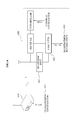
- FIG. 1 illustrates a configuration of a wireless power transmission device 100.
- the wireless power transmission device 100 may include a transmitter 101 and a controller 102.
- the wireless power transmission device 100 may further include a power source 104.
- the wireless power transmission device 100 may be any device capable of wirelessly transmitting power to a terminal 110. Additionally, the wireless power transmission device 100 may be inserted as a module into the terminal 110.
- the terminal 110 may be any device capable of being operated by power, e.g., a television (TV), a mobile phone, a game console, a refrigerator, or other devices.
- the transmitter 101 may wirelessly transmit power to the terminal 110.
- the controller 102 may control an amount of the power transmitted wirelessly by the transmitter 101, based on transmission information 103 transmitted to the terminal 110.
- the wireless power transmission device 100 may transmit the transmission information 103 to the terminal 110 by controlling the amount of the power, rather than by using an additional device for transmission of the transmission information 103.
- the controller 102 may control the amount of the power to be reduced, or in response to the transmission information being "1", the controller 102 may control the amount of the power to be increased. It should be appreciated that the use of "0" and "1" is for example purposes only, and the specific numbers may be reversed or otherwise changed.
- the “transmission information 103" refers to information to be transmitted by the wireless power transmission device 100 to the terminal 110.
- the transmission information 103 may include information regarding the wireless power transmission device 100, for example, an identification (ID) and a type for the wireless power transmission device 100, information regarding a transmission range which may enable the wireless power transmission device 100 to wirelessly transmit power, and information regarding whether the wireless power transmission device 100 is successfully matched with the terminal 110 when wirelessly transmitting the power.
- ID identification
- the transmission information 103 may include various types of information which the wireless power transmission device 100 desires to transmit to the terminal 110, regardless of contents of the information to be transmitted.
- the transmission information 103 may be binary scale data, although embodiments are not limited thereto.
- the wireless power transmission device 100 may further include an input unit 105 to receive the transmission information 103.
- the controller 102 may control a transmission frequency based on the transmission information 103.
- the controller 102 may also control the amount of the power transmitted to the terminal 110, by controlling the transmission frequency.
- the controller 102 may include a phase locked loop (PLL) circuit, to control the transmission frequency using the PLL circuit.
- PLL phase locked loop
- the controller 102 may control an internal impedance of the wireless power transmission device 100 based on the transmission information 103.
- the controller 102 may also control the amount of the power transmitted to the terminal 110, by controlling the internal impedance.
- FIG. 2 illustrates a configuration of a wireless power transmission device 200.
- a controller 210 of the wireless power transmission device 200 may include a switch 220.
- the switch 220 may cut off or supply power (e.g., from the power source 104 of FIG. 1 ) which may be transmitted by the wireless power transmission device 200 wirelessly to a terminal, depending on transmission information 230.
- the switch 220 in response to the transmission information 230 being "0", the switch 220 may be opened to cut off the wirelessly transmitted power, or alternatively in response to the transmission information 230 being "1", the switch 220 may be closed to supply the wirelessly transmitted power.
- FIG. 3 illustrates a configuration of a wireless power transmission device 300.
- the wireless power transmission device 300 may include a measuring unit 301 and an analyzer 302.
- the wireless power transmission device 300 may further include a power source (e.g., power source 104), a controller (e.g., controller 102 or 200), and a transmitter (e.g., transmitter 101).
- a power source e.g., power source 104
- a controller e.g., controller 102 or 200
- a transmitter e.g., transmitter 101
- the wireless power transmission device 300 may send a transmission signal 320 to a terminal 310, in order to wirelessly transmit power to the terminal 310.
- a part of the transmission signal 320 may be reflected and returned, which is referred to as a "reflected wave 330.”
- the measuring unit 301 may measure the reflected wave 330 of the transmission signal 320 transmitted to the terminal 310.
- the measuring unit 301 may include a directional coupler 304, to measure the reflected wave 330 using the directional coupler.
- the analyzer 302 may analyze terminal information 311 received from the terminal 310.
- the terminal 310 may transmit the terminal information 311 to the wireless power transmission device 300.
- An example of a terminal for transmitting terminal information will be further described with reference to FIG. 4 .
- FIG. 4 illustrates a configuration of a terminal 400.
- the terminal 400 may include a receiver 401 and a controller 402.
- the receiver 401 may wirelessly receive power from a wireless power transmission device 410.
- the controller 402 may control an internal impedance of the terminal 400, based on terminal information 403 transmitted to the wireless power transmission device 410.
- the terminal 400 may send the terminal information 403 to the wireless power transmission device 410 by controlling the internal impedance and controlling a reflected wave 430 of a transmission signal 420 received from the wireless power transmission device 410, rather than by using an additional device for transmission of the terminal information 403.
- the controller 402 may control the internal impedance such that a power of the reflected wave 430 may be reduced.
- the controller 402 may control the internal impedance such that the power of the reflected wave 430 may be increased.
- the controller 402 may control the internal impedance such that an amplitude of the reflected wave 430 may increase or decrease, depending on the terminal information 403.
- the terminal information 403 refers to information to be transmitted by the terminal 400 to the wireless power transmission device 410.
- the terminal information 403 may include information regarding whether the terminal 400 may currently require power, information regarding an amount of power that may be required by the terminal 400 in response to the terminal 400 may require the power, information regarding whether the terminal 400 is sufficiently matched with the wireless power transmission device 410 when wirelessly receiving the power, and information regarding a charging rate of the terminal 400.
- the terminal information 403 may include various types of information which the terminal 400 desires to transmit to the wireless power transmission device 410, regardless of contents of the information to be transmitted by the terminal 400.
- the terminal information 403 may be binary scale data, although embodiments are not limited thereto.
- the terminal 400 may further include an input unit (e.g., input unit 105 of FIG. 1 ) to receive the terminal information 403.
- an input unit e.g., input unit 105 of FIG. 1
- the analyzer 302 may analyze the received terminal information 311, based on information on at least one of a variation in power and amplitude of the reflected wave 330 measured by the measuring unit 301.
- the wireless power transmission device 300 may further include an output unit 305 to output the terminal information 303 analyzed by the analyzer 302.
- FIG. 5 illustrates a configuration of a terminal 500.
- a controller 510 of the terminal 500 may include a first load 520, a second load 530, and a switch 540.
- the switch 540 may be connected to either the first load 520 or the second load 530, depending on terminal information 550. In one example, in response to the terminal information 550 being "0", the switch 540 may be connected to the first load 520, and in response to the terminal information 550 being "1", the switch 540 may be connected to the second load 530.
- FIG. 6 illustrates a configuration of a terminal 600.
- the terminal 600 may include a measuring unit 601 and an analyzer 602.
- the measuring unit 601 may measure an amount of power received wirelessly from a wireless power transmission device 610.
- the analyzer 602 may analyze transmission information 611 received from the wireless power transmission device 610. For example, the analyzer 602 may analyze the transmission information 611 1 based on a variation in the measured amount of power.
- the terminal 600 may further include an output unit (e.g., output unit 305 of FIG. 3 ) to output transmission information 603 analyzed by the analyzer 602.
- FIG. 7 illustrates a wireless power transmission method
- power may be wirelessly transmitted to a terminal in operation 710.
- An amount of power transmitted wirelessly to the terminal may be controlled based on transmission information transmitted to the terminal in operation 720.
- the amount of power may be controlled by controlling internal impedance and controlling a reflected wave of a transmission signal received from a wireless power transmission device, rather than an additional device for transmission of the transmission information being used, such that the transmission information may be transmitted to the terminal. For example, in response to the transmission information being "0", the amount of power may be controlled to be reduced, or in response to the transmission information being "1", the amount of power may be controlled to be increased.
- the wireless power transmission method of FIG. 7 may further include receiving the transmission information before operation 720.
- a transmission frequency may be controlled based on the transmission information; accordingly, the amount of power may also be controlled. Additionally, the transmission frequency may be controlled using a PLL circuit.
- an internal impedance may be controlled based on the transmission information; accordingly, the amount of power may also be controlled.
- a reflected wave of a transmission signal transmitted to the terminal may be measured.
- a directional coupler may be used to measure the reflected wave.
- terminal information received from the terminal may be analyzed based on the reflected wave as measured.
- the terminal information may be analyzed based on information on at least one of a variation in power and amplitude of the reflected wave.
- the wireless power transmission method of FIG. 7 may further include outputting the analyzed terminal information.
- the method of the example described in FIG. 7 may use any of the above-described devices for its operation or any devices consistent with the operation described herein.
- the devices e.g., the wireless power transmission device 100 or the terminal 110, described herein may refer to mobile devices such as a cellular phone, a personal digital assistant (PDA), a digital camera, a portable game console, and an MP3 player, a portable/personal multimedia player (PMP), a handheld e-book, a portable tablet and/or laptop PC, a global positioning system (GPS) navigation, and devices such as a desktop PC, a high definition television (HDTV), an optical disc player, a setup and/or set top box, and the like consistent with that disclosed herein.
- mobile devices such as a cellular phone, a personal digital assistant (PDA), a digital camera, a portable game console, and an MP3 player, a portable/personal multimedia player (PMP), a handheld e-book, a portable tablet and/or laptop PC, a global positioning system (GPS) navigation, and devices such as a desktop PC, a high definition television (HDTV), an optical disc player, a setup and/or set top box
Landscapes
- Engineering & Computer Science (AREA)
- Power Engineering (AREA)
- Computer Networks & Wireless Communication (AREA)
- Signal Processing (AREA)
- Transmitters (AREA)
- Near-Field Transmission Systems (AREA)
- Charge And Discharge Circuits For Batteries Or The Like (AREA)
Applications Claiming Priority (1)
| Application Number | Priority Date | Filing Date | Title |
|---|---|---|---|
| KR1020090130852A KR101702861B1 (ko) | 2009-12-24 | 2009-12-24 | 무선 전력 전송 장치 및 방법 |
Publications (3)
| Publication Number | Publication Date |
|---|---|
| EP2348603A2 true EP2348603A2 (fr) | 2011-07-27 |
| EP2348603A3 EP2348603A3 (fr) | 2011-08-10 |
| EP2348603B1 EP2348603B1 (fr) | 2017-01-25 |
Family
ID=44065315
Family Applications (1)
| Application Number | Title | Priority Date | Filing Date |
|---|---|---|---|
| EP10190763.2A Not-in-force EP2348603B1 (fr) | 2009-12-24 | 2010-11-10 | Dispositif de transmission de puissance sans fil et procédé |
Country Status (3)
| Country | Link |
|---|---|
| US (1) | US9048695B2 (fr) |
| EP (1) | EP2348603B1 (fr) |
| KR (1) | KR101702861B1 (fr) |
Cited By (1)
| Publication number | Priority date | Publication date | Assignee | Title |
|---|---|---|---|---|
| EP2806528A1 (fr) * | 2013-05-24 | 2014-11-26 | Koninklijke Philips N.V. | Procédé et système de transfert d'énergie et de données |
Families Citing this family (20)
| Publication number | Priority date | Publication date | Assignee | Title |
|---|---|---|---|---|
| CN102934327B (zh) * | 2011-03-11 | 2015-11-25 | 海尔集团公司 | 无线供电装置和方法 |
| US9748790B2 (en) | 2012-01-12 | 2017-08-29 | Facebook, Inc. | System and method for a variable impedance transmitter path for charging wireless devices |
| US8933589B2 (en) | 2012-02-07 | 2015-01-13 | The Gillette Company | Wireless power transfer using separately tunable resonators |
| KR101863968B1 (ko) | 2012-06-01 | 2018-06-04 | 한국전자통신연구원 | 에너지 전송 시스템에서 무선 에너지 송수신 장치 및 그 방법 |
| KR101455693B1 (ko) * | 2012-11-26 | 2014-11-03 | 한국전기연구원 | 다중 무선전력수신기를 지원하는 무선전력전송시스템 |
| KR101767276B1 (ko) | 2012-12-03 | 2017-08-10 | 한국전자통신연구원 | 무선 전력 전송을 이용하는 배터리 충전 방법 및 시스템 |
| KR102042103B1 (ko) | 2013-01-24 | 2019-11-07 | 한국전자통신연구원 | 고차모드 공진을 이용한 자기공명 무선전력 전송 장치와 수신 단말 및 그 무선전력 송수신 방법 |
| US9543790B2 (en) | 2013-01-24 | 2017-01-10 | Electronics And Telecommunications Research Institute | Apparatus for transmitting magnetic resonance wireless power using higher order mode resonance, receiving terminal, and method for transmitting and receiving wireless power using the same |
| JP5879294B2 (ja) | 2013-03-29 | 2016-03-08 | 日立オートモティブシステムズ株式会社 | 電池システム |
| US9635222B2 (en) | 2014-08-03 | 2017-04-25 | PogoTec, Inc. | Wearable camera systems and apparatus for aligning an eyewear camera |
| RU2017106629A (ru) | 2014-08-03 | 2018-09-04 | Поготек, Инк. | Система носимых камер и устройств, а также способ прикрепления систем камер или других электронных устройств к носимым изделиям |
| KR102429819B1 (ko) | 2014-11-27 | 2022-08-08 | 한국전자통신연구원 | 무선 전력 수신 장치 및 그의 전력 제어 방법, 그리고 무선 전력 시스템 |
| US10020669B2 (en) | 2014-11-27 | 2018-07-10 | Electronics And Telecommunications Research Institute | Wireless power receiving apparatus and power control method thereof, and wireless power system |
| BR112017013618A2 (pt) | 2014-12-23 | 2018-06-19 | Pogotec Inc | câmeras, sistemas e métodos para receber energia sem fio |
| JP2018521345A (ja) | 2015-06-10 | 2018-08-02 | ポゴテック インクPogoTec, Inc. | ウェアラブル電子機器用の磁気的トラックを備えたアイウェア |
| US10481417B2 (en) | 2015-06-10 | 2019-11-19 | PogoTec, Inc. | Magnetic attachment mechanism for electronic wearable device |
| US10341787B2 (en) | 2015-10-29 | 2019-07-02 | PogoTec, Inc. | Hearing aid adapted for wireless power reception |
| US11558538B2 (en) | 2016-03-18 | 2023-01-17 | Opkix, Inc. | Portable camera system |
| EP3539285A4 (fr) | 2016-11-08 | 2020-09-02 | Pogotec, Inc. | Boîtier intelligent de dispositif électronique portatif |
| US11300857B2 (en) | 2018-11-13 | 2022-04-12 | Opkix, Inc. | Wearable mounts for portable camera |
Family Cites Families (22)
| Publication number | Priority date | Publication date | Assignee | Title |
|---|---|---|---|---|
| JPH10225129A (ja) * | 1997-02-13 | 1998-08-21 | Ishikawajima Harima Heavy Ind Co Ltd | 非接触給電設備 |
| JP2002015237A (ja) * | 2000-06-30 | 2002-01-18 | Toshiba Corp | 課金制御システムおよび端末装置 |
| FR2815490B1 (fr) * | 2000-10-16 | 2006-07-07 | Inside Technologies | Lecteur de circuit integre sans contact |
| US6798716B1 (en) * | 2003-06-19 | 2004-09-28 | Bc Systems, Inc. | System and method for wireless electrical power transmission |
| JP4710321B2 (ja) * | 2004-02-02 | 2011-06-29 | ソニー株式会社 | 無線通信システム、無線通信装置及び無線通信方法、並びにコンピュータ・プログラム |
| US20060033482A1 (en) * | 2004-08-06 | 2006-02-16 | Stmicroelectronics S.A. | Supply of several loads by A D.C./D.C. converter |
| JP4666281B2 (ja) * | 2005-03-01 | 2011-04-06 | ブラザー工業株式会社 | 無線タグ回路素子及びタグラベル作成装置 |
| GB0505060D0 (en) * | 2005-03-11 | 2005-04-20 | Innovision Res & Tech Plc | Gain controlled impedance |
| EP1943740B1 (fr) * | 2005-09-12 | 2016-07-27 | Sato Holdings Corporation | Procede et appareil destines a emettre des donnees |
| JP2007288352A (ja) * | 2006-04-13 | 2007-11-01 | Mitsubishi Electric Corp | アンテナ装置 |
| KR101322764B1 (ko) | 2006-10-30 | 2013-10-29 | 엘지전자 주식회사 | 무선 전원 공급 장치 및 그 방법 |
| US8107968B2 (en) * | 2006-12-11 | 2012-01-31 | Nokia Corporation | Radio transmission scheduling according to multiradio control in a radio modem |
| JP4308858B2 (ja) * | 2007-02-16 | 2009-08-05 | セイコーエプソン株式会社 | 送電制御装置、受電制御装置、無接点電力伝送システム、送電装置、受電装置および電子機器 |
| KR100898768B1 (ko) | 2007-05-07 | 2009-05-20 | 전자부품연구원 | 무선신호의 하모닉성분을 이용한 전력공급장치 및 방법 |
| US7825625B2 (en) * | 2007-06-29 | 2010-11-02 | Intel Corporation | Wireless charging device with reflected power communication |
| KR100913558B1 (ko) | 2007-07-11 | 2009-08-21 | 주식회사 한림포스텍 | 무선주변기기용 무선전력전송장치를 구비한무선전력전송시스템 및 그의 제어방법 |
| KR20090019310A (ko) | 2007-08-20 | 2009-02-25 | 최성규 | 무선전력 공급장치가 구비된 경관조명 |
| JP4600462B2 (ja) * | 2007-11-16 | 2010-12-15 | セイコーエプソン株式会社 | 送電制御装置、送電装置、電子機器及び無接点電力伝送システム |
| JP4407753B2 (ja) * | 2008-01-15 | 2010-02-03 | トヨタ自動車株式会社 | 電動車両の充電システム |
| JP4725611B2 (ja) * | 2008-07-16 | 2011-07-13 | セイコーエプソン株式会社 | 送電制御装置、送電装置、受電制御装置、受電装置及び電子機器 |
| US8587153B2 (en) * | 2008-09-27 | 2013-11-19 | Witricity Corporation | Wireless energy transfer using high Q resonators for lighting applications |
| US8923015B2 (en) * | 2008-11-26 | 2014-12-30 | Auckland Uniservices Limited | Primary-side power control for inductive power transfer |
-
2009
- 2009-12-24 KR KR1020090130852A patent/KR101702861B1/ko active IP Right Grant
-
2010
- 2010-11-10 EP EP10190763.2A patent/EP2348603B1/fr not_active Not-in-force
- 2010-12-20 US US12/972,659 patent/US9048695B2/en not_active Expired - Fee Related
Non-Patent Citations (1)
| Title |
|---|
| None |
Cited By (1)
| Publication number | Priority date | Publication date | Assignee | Title |
|---|---|---|---|---|
| EP2806528A1 (fr) * | 2013-05-24 | 2014-11-26 | Koninklijke Philips N.V. | Procédé et système de transfert d'énergie et de données |
Also Published As
| Publication number | Publication date |
|---|---|
| US20110156490A1 (en) | 2011-06-30 |
| US9048695B2 (en) | 2015-06-02 |
| EP2348603B1 (fr) | 2017-01-25 |
| EP2348603A3 (fr) | 2011-08-10 |
| KR101702861B1 (ko) | 2017-02-23 |
| KR20110074020A (ko) | 2011-06-30 |
Similar Documents
| Publication | Publication Date | Title |
|---|---|---|
| US9048695B2 (en) | Wireless power transmission device and method | |
| CN102640396B (zh) | 负载阻抗决定装置、无线电力传输装置及无线电力传输方法 | |
| CN108695921B (zh) | 数据备份方法、无线充电装置、移动终端及存储介质 | |
| US9893558B2 (en) | Wireless charging device and method | |
| EP2312726A2 (fr) | Dispositif de transmission de puissance sans fil, dispositif de contrôle de transmission de puissance sans fil et procédé de transmission de puissance sans fil | |
| CN203433115U (zh) | Gps天线模组及便携式电子装置 | |
| CN103620623B (zh) | 非接触收发系统发射的电磁信号的幅度调制方法及设备 | |
| CN211742146U (zh) | 近场通信电路及电子设备 | |
| US10496567B2 (en) | Wireless configurable flash memory | |
| CN105870589A (zh) | 移动终端 | |
| KR101661363B1 (ko) | 대기전력 제어방법 및 그 방법을 이용한 제어장치 | |
| US20110275407A1 (en) | Mobile phone and control method thereof | |
| CN203466832U (zh) | 一种基于nfc的动态令牌系统 | |
| US20120081069A1 (en) | Communication apparatus and signal processing method | |
| US20090066479A1 (en) | Electronic Device Capable of Identifying External Antennas and Related External Antenna Module | |
| US20020186164A1 (en) | Searching apparatus | |
| US8331922B2 (en) | Remote host controller interface control for devices | |
| CN214851221U (zh) | 基于5g模组的开发板 | |
| EP4191892A1 (fr) | Dispositif de communication en champ proche, dispositif terminal le comprenant, et procédé de fonctionnement du dispositif de communication en champ proche | |
| CN104010017A (zh) | 终端设备和用于其的信息处理方法 | |
| EP2945296B1 (fr) | Appareil de communication à étalement de spectre | |
| TWI475779B (zh) | 無線充電方法及系統 | |
| CN103077409B (zh) | 数据交换系统及数据交换方法、存储设备 | |
| TWI408988B (zh) | 行動裝置的電池模組和傳收模組 | |
| KR20230083959A (ko) | Nfc 장치, nfc 장치를 포함하는 단말 장치, 및 nfc 장치의 동작 방법 |
Legal Events
| Date | Code | Title | Description |
|---|---|---|---|
| PUAI | Public reference made under article 153(3) epc to a published international application that has entered the european phase |
Free format text: ORIGINAL CODE: 0009012 |
|
| PUAL | Search report despatched |
Free format text: ORIGINAL CODE: 0009013 |
|
| AK | Designated contracting states |
Kind code of ref document: A2 Designated state(s): AL AT BE BG CH CY CZ DE DK EE ES FI FR GB GR HR HU IE IS IT LI LT LU LV MC MK MT NL NO PL PT RO RS SE SI SK SM TR |
|
| AX | Request for extension of the european patent |
Extension state: BA ME |
|
| RIC1 | Information provided on ipc code assigned before grant |
Ipc: H02J 7/02 20060101ALI20110629BHEP Ipc: H02J 7/00 20060101AFI20110629BHEP Ipc: H02J 17/00 20060101ALI20110629BHEP |
|
| AK | Designated contracting states |
Kind code of ref document: A3 Designated state(s): AL AT BE BG CH CY CZ DE DK EE ES FI FR GB GR HR HU IE IS IT LI LT LU LV MC MK MT NL NO PL PT RO RS SE SI SK SM TR |
|
| AX | Request for extension of the european patent |
Extension state: BA ME |
|
| 17P | Request for examination filed |
Effective date: 20120210 |
|
| 17Q | First examination report despatched |
Effective date: 20120418 |
|
| RAP1 | Party data changed (applicant data changed or rights of an application transferred) |
Owner name: SAMSUNG ELECTRONICS CO., LTD. |
|
| REG | Reference to a national code |
Ref country code: DE Ref legal event code: R079 Ref document number: 602010039761 Country of ref document: DE Free format text: PREVIOUS MAIN CLASS: H02J0007000000 Ipc: H02J0050800000 |
|
| GRAP | Despatch of communication of intention to grant a patent |
Free format text: ORIGINAL CODE: EPIDOSNIGR1 |
|
| RIC1 | Information provided on ipc code assigned before grant |
Ipc: H02J 50/80 20160101AFI20160729BHEP |
|
| INTG | Intention to grant announced |
Effective date: 20160819 |
|
| GRAS | Grant fee paid |
Free format text: ORIGINAL CODE: EPIDOSNIGR3 |
|
| GRAA | (expected) grant |
Free format text: ORIGINAL CODE: 0009210 |
|
| AK | Designated contracting states |
Kind code of ref document: B1 Designated state(s): AL AT BE BG CH CY CZ DE DK EE ES FI FR GB GR HR HU IE IS IT LI LT LU LV MC MK MT NL NO PL PT RO RS SE SI SK SM TR |
|
| REG | Reference to a national code |
Ref country code: GB Ref legal event code: FG4D |
|
| REG | Reference to a national code |
Ref country code: CH Ref legal event code: EP |
|
| REG | Reference to a national code |
Ref country code: AT Ref legal event code: REF Ref document number: 864627 Country of ref document: AT Kind code of ref document: T Effective date: 20170215 |
|
| REG | Reference to a national code |
Ref country code: IE Ref legal event code: FG4D |
|
| REG | Reference to a national code |
Ref country code: DE Ref legal event code: R096 Ref document number: 602010039761 Country of ref document: DE |
|
| REG | Reference to a national code |
Ref country code: LT Ref legal event code: MG4D |
|
| REG | Reference to a national code |
Ref country code: NL Ref legal event code: MP Effective date: 20170125 |
|
| REG | Reference to a national code |
Ref country code: AT Ref legal event code: MK05 Ref document number: 864627 Country of ref document: AT Kind code of ref document: T Effective date: 20170125 |
|
| PG25 | Lapsed in a contracting state [announced via postgrant information from national office to epo] |
Ref country code: NL Free format text: LAPSE BECAUSE OF FAILURE TO SUBMIT A TRANSLATION OF THE DESCRIPTION OR TO PAY THE FEE WITHIN THE PRESCRIBED TIME-LIMIT Effective date: 20170125 |
|
| PG25 | Lapsed in a contracting state [announced via postgrant information from national office to epo] |
Ref country code: IS Free format text: LAPSE BECAUSE OF FAILURE TO SUBMIT A TRANSLATION OF THE DESCRIPTION OR TO PAY THE FEE WITHIN THE PRESCRIBED TIME-LIMIT Effective date: 20170525 Ref country code: FI Free format text: LAPSE BECAUSE OF FAILURE TO SUBMIT A TRANSLATION OF THE DESCRIPTION OR TO PAY THE FEE WITHIN THE PRESCRIBED TIME-LIMIT Effective date: 20170125 Ref country code: HR Free format text: LAPSE BECAUSE OF FAILURE TO SUBMIT A TRANSLATION OF THE DESCRIPTION OR TO PAY THE FEE WITHIN THE PRESCRIBED TIME-LIMIT Effective date: 20170125 Ref country code: NO Free format text: LAPSE BECAUSE OF FAILURE TO SUBMIT A TRANSLATION OF THE DESCRIPTION OR TO PAY THE FEE WITHIN THE PRESCRIBED TIME-LIMIT Effective date: 20170425 Ref country code: GR Free format text: LAPSE BECAUSE OF FAILURE TO SUBMIT A TRANSLATION OF THE DESCRIPTION OR TO PAY THE FEE WITHIN THE PRESCRIBED TIME-LIMIT Effective date: 20170426 Ref country code: LT Free format text: LAPSE BECAUSE OF FAILURE TO SUBMIT A TRANSLATION OF THE DESCRIPTION OR TO PAY THE FEE WITHIN THE PRESCRIBED TIME-LIMIT Effective date: 20170125 |
|
| PG25 | Lapsed in a contracting state [announced via postgrant information from national office to epo] |
Ref country code: LV Free format text: LAPSE BECAUSE OF FAILURE TO SUBMIT A TRANSLATION OF THE DESCRIPTION OR TO PAY THE FEE WITHIN THE PRESCRIBED TIME-LIMIT Effective date: 20170125 Ref country code: PT Free format text: LAPSE BECAUSE OF FAILURE TO SUBMIT A TRANSLATION OF THE DESCRIPTION OR TO PAY THE FEE WITHIN THE PRESCRIBED TIME-LIMIT Effective date: 20170525 Ref country code: PL Free format text: LAPSE BECAUSE OF FAILURE TO SUBMIT A TRANSLATION OF THE DESCRIPTION OR TO PAY THE FEE WITHIN THE PRESCRIBED TIME-LIMIT Effective date: 20170125 Ref country code: RS Free format text: LAPSE BECAUSE OF FAILURE TO SUBMIT A TRANSLATION OF THE DESCRIPTION OR TO PAY THE FEE WITHIN THE PRESCRIBED TIME-LIMIT Effective date: 20170125 Ref country code: ES Free format text: LAPSE BECAUSE OF FAILURE TO SUBMIT A TRANSLATION OF THE DESCRIPTION OR TO PAY THE FEE WITHIN THE PRESCRIBED TIME-LIMIT Effective date: 20170125 Ref country code: SE Free format text: LAPSE BECAUSE OF FAILURE TO SUBMIT A TRANSLATION OF THE DESCRIPTION OR TO PAY THE FEE WITHIN THE PRESCRIBED TIME-LIMIT Effective date: 20170125 Ref country code: AT Free format text: LAPSE BECAUSE OF FAILURE TO SUBMIT A TRANSLATION OF THE DESCRIPTION OR TO PAY THE FEE WITHIN THE PRESCRIBED TIME-LIMIT Effective date: 20170125 Ref country code: BG Free format text: LAPSE BECAUSE OF FAILURE TO SUBMIT A TRANSLATION OF THE DESCRIPTION OR TO PAY THE FEE WITHIN THE PRESCRIBED TIME-LIMIT Effective date: 20170425 |
|
| REG | Reference to a national code |
Ref country code: DE Ref legal event code: R097 Ref document number: 602010039761 Country of ref document: DE |
|
| PG25 | Lapsed in a contracting state [announced via postgrant information from national office to epo] |
Ref country code: IT Free format text: LAPSE BECAUSE OF FAILURE TO SUBMIT A TRANSLATION OF THE DESCRIPTION OR TO PAY THE FEE WITHIN THE PRESCRIBED TIME-LIMIT Effective date: 20170125 Ref country code: SK Free format text: LAPSE BECAUSE OF FAILURE TO SUBMIT A TRANSLATION OF THE DESCRIPTION OR TO PAY THE FEE WITHIN THE PRESCRIBED TIME-LIMIT Effective date: 20170125 Ref country code: RO Free format text: LAPSE BECAUSE OF FAILURE TO SUBMIT A TRANSLATION OF THE DESCRIPTION OR TO PAY THE FEE WITHIN THE PRESCRIBED TIME-LIMIT Effective date: 20170125 Ref country code: EE Free format text: LAPSE BECAUSE OF FAILURE TO SUBMIT A TRANSLATION OF THE DESCRIPTION OR TO PAY THE FEE WITHIN THE PRESCRIBED TIME-LIMIT Effective date: 20170125 Ref country code: CZ Free format text: LAPSE BECAUSE OF FAILURE TO SUBMIT A TRANSLATION OF THE DESCRIPTION OR TO PAY THE FEE WITHIN THE PRESCRIBED TIME-LIMIT Effective date: 20170125 |
|
| PG25 | Lapsed in a contracting state [announced via postgrant information from national office to epo] |
Ref country code: DK Free format text: LAPSE BECAUSE OF FAILURE TO SUBMIT A TRANSLATION OF THE DESCRIPTION OR TO PAY THE FEE WITHIN THE PRESCRIBED TIME-LIMIT Effective date: 20170125 Ref country code: SM Free format text: LAPSE BECAUSE OF FAILURE TO SUBMIT A TRANSLATION OF THE DESCRIPTION OR TO PAY THE FEE WITHIN THE PRESCRIBED TIME-LIMIT Effective date: 20170125 |
|
| PLBE | No opposition filed within time limit |
Free format text: ORIGINAL CODE: 0009261 |
|
| STAA | Information on the status of an ep patent application or granted ep patent |
Free format text: STATUS: NO OPPOSITION FILED WITHIN TIME LIMIT |
|
| 26N | No opposition filed |
Effective date: 20171026 |
|
| PGFP | Annual fee paid to national office [announced via postgrant information from national office to epo] |
Ref country code: DE Payment date: 20171018 Year of fee payment: 8 |
|
| PG25 | Lapsed in a contracting state [announced via postgrant information from national office to epo] |
Ref country code: SI Free format text: LAPSE BECAUSE OF FAILURE TO SUBMIT A TRANSLATION OF THE DESCRIPTION OR TO PAY THE FEE WITHIN THE PRESCRIBED TIME-LIMIT Effective date: 20170125 |
|
| PGFP | Annual fee paid to national office [announced via postgrant information from national office to epo] |
Ref country code: GB Payment date: 20171019 Year of fee payment: 8 |
|
| PG25 | Lapsed in a contracting state [announced via postgrant information from national office to epo] |
Ref country code: MC Free format text: LAPSE BECAUSE OF FAILURE TO SUBMIT A TRANSLATION OF THE DESCRIPTION OR TO PAY THE FEE WITHIN THE PRESCRIBED TIME-LIMIT Effective date: 20170125 |
|
| PG25 | Lapsed in a contracting state [announced via postgrant information from national office to epo] |
Ref country code: LI Free format text: LAPSE BECAUSE OF NON-PAYMENT OF DUE FEES Effective date: 20171130 Ref country code: CH Free format text: LAPSE BECAUSE OF NON-PAYMENT OF DUE FEES Effective date: 20171130 |
|
| PG25 | Lapsed in a contracting state [announced via postgrant information from national office to epo] |
Ref country code: LU Free format text: LAPSE BECAUSE OF NON-PAYMENT OF DUE FEES Effective date: 20171110 |
|
| REG | Reference to a national code |
Ref country code: FR Ref legal event code: ST Effective date: 20180731 Ref country code: BE Ref legal event code: MM Effective date: 20171130 |
|
| REG | Reference to a national code |
Ref country code: IE Ref legal event code: MM4A |
|
| PG25 | Lapsed in a contracting state [announced via postgrant information from national office to epo] |
Ref country code: MT Free format text: LAPSE BECAUSE OF NON-PAYMENT OF DUE FEES Effective date: 20171110 |
|
| PG25 | Lapsed in a contracting state [announced via postgrant information from national office to epo] |
Ref country code: FR Free format text: LAPSE BECAUSE OF NON-PAYMENT OF DUE FEES Effective date: 20171130 Ref country code: IE Free format text: LAPSE BECAUSE OF NON-PAYMENT OF DUE FEES Effective date: 20171110 |
|
| PG25 | Lapsed in a contracting state [announced via postgrant information from national office to epo] |
Ref country code: BE Free format text: LAPSE BECAUSE OF NON-PAYMENT OF DUE FEES Effective date: 20171130 |
|
| REG | Reference to a national code |
Ref country code: DE Ref legal event code: R119 Ref document number: 602010039761 Country of ref document: DE |
|
| PG25 | Lapsed in a contracting state [announced via postgrant information from national office to epo] |
Ref country code: HU Free format text: LAPSE BECAUSE OF FAILURE TO SUBMIT A TRANSLATION OF THE DESCRIPTION OR TO PAY THE FEE WITHIN THE PRESCRIBED TIME-LIMIT; INVALID AB INITIO Effective date: 20101110 |
|
| GBPC | Gb: european patent ceased through non-payment of renewal fee |
Effective date: 20181110 |
|
| PG25 | Lapsed in a contracting state [announced via postgrant information from national office to epo] |
Ref country code: DE Free format text: LAPSE BECAUSE OF NON-PAYMENT OF DUE FEES Effective date: 20190601 Ref country code: CY Free format text: LAPSE BECAUSE OF NON-PAYMENT OF DUE FEES Effective date: 20170125 |
|
| PG25 | Lapsed in a contracting state [announced via postgrant information from national office to epo] |
Ref country code: MK Free format text: LAPSE BECAUSE OF FAILURE TO SUBMIT A TRANSLATION OF THE DESCRIPTION OR TO PAY THE FEE WITHIN THE PRESCRIBED TIME-LIMIT Effective date: 20170125 |
|
| PG25 | Lapsed in a contracting state [announced via postgrant information from national office to epo] |
Ref country code: GB Free format text: LAPSE BECAUSE OF NON-PAYMENT OF DUE FEES Effective date: 20181110 |
|
| PG25 | Lapsed in a contracting state [announced via postgrant information from national office to epo] |
Ref country code: TR Free format text: LAPSE BECAUSE OF FAILURE TO SUBMIT A TRANSLATION OF THE DESCRIPTION OR TO PAY THE FEE WITHIN THE PRESCRIBED TIME-LIMIT Effective date: 20170125 |
|
| PG25 | Lapsed in a contracting state [announced via postgrant information from national office to epo] |
Ref country code: AL Free format text: LAPSE BECAUSE OF FAILURE TO SUBMIT A TRANSLATION OF THE DESCRIPTION OR TO PAY THE FEE WITHIN THE PRESCRIBED TIME-LIMIT Effective date: 20170125 |