EP2348254B1 - Betankungsanlage für ein mobile Maschine - Google Patents
Betankungsanlage für ein mobile Maschine Download PDFInfo
- Publication number
- EP2348254B1 EP2348254B1 EP10151481.8A EP10151481A EP2348254B1 EP 2348254 B1 EP2348254 B1 EP 2348254B1 EP 10151481 A EP10151481 A EP 10151481A EP 2348254 B1 EP2348254 B1 EP 2348254B1
- Authority
- EP
- European Patent Office
- Prior art keywords
- carbon dioxide
- water
- gas
- drive device
- fuel
- Prior art date
- Legal status (The legal status is an assumption and is not a legal conclusion. Google has not performed a legal analysis and makes no representation as to the accuracy of the status listed.)
- Active
Links
- CURLTUGMZLYLDI-UHFFFAOYSA-N Carbon dioxide Chemical compound O=C=O CURLTUGMZLYLDI-UHFFFAOYSA-N 0.000 claims description 109
- 239000007789 gas Substances 0.000 claims description 80
- 239000001569 carbon dioxide Substances 0.000 claims description 54
- 229910002092 carbon dioxide Inorganic materials 0.000 claims description 54
- 239000000446 fuel Substances 0.000 claims description 45
- XLYOFNOQVPJJNP-UHFFFAOYSA-N water Substances O XLYOFNOQVPJJNP-UHFFFAOYSA-N 0.000 claims description 45
- 229910052760 oxygen Inorganic materials 0.000 claims description 20
- QVGXLLKOCUKJST-UHFFFAOYSA-N atomic oxygen Chemical compound [O] QVGXLLKOCUKJST-UHFFFAOYSA-N 0.000 claims description 19
- 239000001301 oxygen Substances 0.000 claims description 19
- 239000007788 liquid Substances 0.000 claims description 15
- 238000003860 storage Methods 0.000 claims description 15
- 238000007254 oxidation reaction Methods 0.000 claims description 12
- 238000009434 installation Methods 0.000 claims description 6
- 230000003647 oxidation Effects 0.000 claims description 5
- 238000002485 combustion reaction Methods 0.000 description 54
- 239000000047 product Substances 0.000 description 22
- 239000000203 mixture Substances 0.000 description 17
- 239000000567 combustion gas Substances 0.000 description 13
- 238000000034 method Methods 0.000 description 13
- 230000015572 biosynthetic process Effects 0.000 description 12
- 238000004519 manufacturing process Methods 0.000 description 12
- 229930195733 hydrocarbon Natural products 0.000 description 11
- 150000002430 hydrocarbons Chemical class 0.000 description 11
- 229910052739 hydrogen Inorganic materials 0.000 description 11
- 239000000463 material Substances 0.000 description 11
- 239000001257 hydrogen Substances 0.000 description 10
- 239000000126 substance Substances 0.000 description 10
- MWUXSHHQAYIFBG-UHFFFAOYSA-N nitrogen oxide Inorganic materials O=[N] MWUXSHHQAYIFBG-UHFFFAOYSA-N 0.000 description 9
- 238000003786 synthesis reaction Methods 0.000 description 9
- UFHFLCQGNIYNRP-UHFFFAOYSA-N Hydrogen Chemical compound [H][H] UFHFLCQGNIYNRP-UHFFFAOYSA-N 0.000 description 8
- 238000006243 chemical reaction Methods 0.000 description 8
- 239000004215 Carbon black (E152) Substances 0.000 description 7
- 239000007858 starting material Substances 0.000 description 7
- 239000003344 environmental pollutant Substances 0.000 description 6
- 231100000719 pollutant Toxicity 0.000 description 6
- 238000000197 pyrolysis Methods 0.000 description 6
- UGFAIRIUMAVXCW-UHFFFAOYSA-N Carbon monoxide Chemical compound [O+]#[C-] UGFAIRIUMAVXCW-UHFFFAOYSA-N 0.000 description 5
- MYMOFIZGZYHOMD-UHFFFAOYSA-N Dioxygen Chemical compound O=O MYMOFIZGZYHOMD-UHFFFAOYSA-N 0.000 description 5
- 229910002091 carbon monoxide Inorganic materials 0.000 description 5
- 239000003575 carbonaceous material Substances 0.000 description 5
- 239000007795 chemical reaction product Substances 0.000 description 5
- 238000004064 recycling Methods 0.000 description 5
- 238000013022 venting Methods 0.000 description 5
- 229910052799 carbon Inorganic materials 0.000 description 4
- 238000009833 condensation Methods 0.000 description 4
- 230000005494 condensation Effects 0.000 description 4
- 238000005516 engineering process Methods 0.000 description 4
- 230000008569 process Effects 0.000 description 4
- OKTJSMMVPCPJKN-UHFFFAOYSA-N Carbon Chemical compound [C] OKTJSMMVPCPJKN-UHFFFAOYSA-N 0.000 description 3
- 230000006835 compression Effects 0.000 description 3
- 238000007906 compression Methods 0.000 description 3
- 238000001816 cooling Methods 0.000 description 3
- 230000005611 electricity Effects 0.000 description 3
- 239000007800 oxidant agent Substances 0.000 description 3
- IJGRMHOSHXDMSA-UHFFFAOYSA-N Atomic nitrogen Chemical compound N#N IJGRMHOSHXDMSA-UHFFFAOYSA-N 0.000 description 2
- OAICVXFJPJFONN-UHFFFAOYSA-N Phosphorus Chemical compound [P] OAICVXFJPJFONN-UHFFFAOYSA-N 0.000 description 2
- NINIDFKCEFEMDL-UHFFFAOYSA-N Sulfur Chemical compound [S] NINIDFKCEFEMDL-UHFFFAOYSA-N 0.000 description 2
- LSNNMFCWUKXFEE-UHFFFAOYSA-N Sulfurous acid Chemical compound OS(O)=O LSNNMFCWUKXFEE-UHFFFAOYSA-N 0.000 description 2
- RAHZWNYVWXNFOC-UHFFFAOYSA-N Sulphur dioxide Chemical compound O=S=O RAHZWNYVWXNFOC-UHFFFAOYSA-N 0.000 description 2
- 238000012993 chemical processing Methods 0.000 description 2
- 239000003795 chemical substances by application Substances 0.000 description 2
- 239000000571 coke Substances 0.000 description 2
- 230000007423 decrease Effects 0.000 description 2
- 238000011049 filling Methods 0.000 description 2
- 239000002828 fuel tank Substances 0.000 description 2
- 150000002431 hydrogen Chemical class 0.000 description 2
- 238000002347 injection Methods 0.000 description 2
- 239000007924 injection Substances 0.000 description 2
- VNWKTOKETHGBQD-UHFFFAOYSA-N methane Chemical compound C VNWKTOKETHGBQD-UHFFFAOYSA-N 0.000 description 2
- VUZPPFZMUPKLLV-UHFFFAOYSA-N methane;hydrate Chemical compound C.O VUZPPFZMUPKLLV-UHFFFAOYSA-N 0.000 description 2
- 230000001590 oxidative effect Effects 0.000 description 2
- 229910052698 phosphorus Inorganic materials 0.000 description 2
- 239000011574 phosphorus Substances 0.000 description 2
- 239000002893 slag Substances 0.000 description 2
- 229910052717 sulfur Inorganic materials 0.000 description 2
- 239000011593 sulfur Substances 0.000 description 2
- AKEJUJNQAAGONA-UHFFFAOYSA-N sulfur trioxide Chemical compound O=S(=O)=O AKEJUJNQAAGONA-UHFFFAOYSA-N 0.000 description 2
- 239000002028 Biomass Substances 0.000 description 1
- 150000001412 amines Chemical class 0.000 description 1
- 230000008901 benefit Effects 0.000 description 1
- 230000005540 biological transmission Effects 0.000 description 1
- 239000003054 catalyst Substances 0.000 description 1
- 230000008859 change Effects 0.000 description 1
- 238000005056 compaction Methods 0.000 description 1
- 230000001419 dependent effect Effects 0.000 description 1
- 230000000694 effects Effects 0.000 description 1
- 238000005265 energy consumption Methods 0.000 description 1
- 230000007613 environmental effect Effects 0.000 description 1
- 238000005429 filling process Methods 0.000 description 1
- 238000001914 filtration Methods 0.000 description 1
- 230000006870 function Effects 0.000 description 1
- 238000002309 gasification Methods 0.000 description 1
- 239000003502 gasoline Substances 0.000 description 1
- 230000007062 hydrolysis Effects 0.000 description 1
- 238000006460 hydrolysis reaction Methods 0.000 description 1
- 238000011068 loading method Methods 0.000 description 1
- 230000007774 longterm Effects 0.000 description 1
- 239000003345 natural gas Substances 0.000 description 1
- 229910052757 nitrogen Inorganic materials 0.000 description 1
- QVGXLLKOCUKJST-OUBTZVSYSA-N oxygen-17 atom Chemical compound [17O] QVGXLLKOCUKJST-OUBTZVSYSA-N 0.000 description 1
- 239000013618 particulate matter Substances 0.000 description 1
- 238000005086 pumping Methods 0.000 description 1
- 239000011541 reaction mixture Substances 0.000 description 1
- 230000009467 reduction Effects 0.000 description 1
- 230000001105 regulatory effect Effects 0.000 description 1
- 239000002904 solvent Substances 0.000 description 1
- 230000003068 static effect Effects 0.000 description 1
- 239000012855 volatile organic compound Substances 0.000 description 1
- 238000010792 warming Methods 0.000 description 1
Images


Classifications
-
- F—MECHANICAL ENGINEERING; LIGHTING; HEATING; WEAPONS; BLASTING
- F23—COMBUSTION APPARATUS; COMBUSTION PROCESSES
- F23J—REMOVAL OR TREATMENT OF COMBUSTION PRODUCTS OR COMBUSTION RESIDUES; FLUES
- F23J15/00—Arrangements of devices for treating smoke or fumes
- F23J15/06—Arrangements of devices for treating smoke or fumes of coolers
-
- F—MECHANICAL ENGINEERING; LIGHTING; HEATING; WEAPONS; BLASTING
- F23—COMBUSTION APPARATUS; COMBUSTION PROCESSES
- F23L—SUPPLYING AIR OR NON-COMBUSTIBLE LIQUIDS OR GASES TO COMBUSTION APPARATUS IN GENERAL ; VALVES OR DAMPERS SPECIALLY ADAPTED FOR CONTROLLING AIR SUPPLY OR DRAUGHT IN COMBUSTION APPARATUS; INDUCING DRAUGHT IN COMBUSTION APPARATUS; TOPS FOR CHIMNEYS OR VENTILATING SHAFTS; TERMINALS FOR FLUES
- F23L7/00—Supplying non-combustible liquids or gases, other than air, to the fire, e.g. oxygen, steam
- F23L7/007—Supplying oxygen or oxygen-enriched air
-
- F—MECHANICAL ENGINEERING; LIGHTING; HEATING; WEAPONS; BLASTING
- F23—COMBUSTION APPARATUS; COMBUSTION PROCESSES
- F23G—CREMATION FURNACES; CONSUMING WASTE PRODUCTS BY COMBUSTION
- F23G2201/00—Pretreatment
- F23G2201/30—Pyrolysing
- F23G2201/303—Burning pyrogases
-
- F—MECHANICAL ENGINEERING; LIGHTING; HEATING; WEAPONS; BLASTING
- F23—COMBUSTION APPARATUS; COMBUSTION PROCESSES
- F23G—CREMATION FURNACES; CONSUMING WASTE PRODUCTS BY COMBUSTION
- F23G2201/00—Pretreatment
- F23G2201/40—Gasification
-
- F—MECHANICAL ENGINEERING; LIGHTING; HEATING; WEAPONS; BLASTING
- F23—COMBUSTION APPARATUS; COMBUSTION PROCESSES
- F23J—REMOVAL OR TREATMENT OF COMBUSTION PRODUCTS OR COMBUSTION RESIDUES; FLUES
- F23J2900/00—Special arrangements for conducting or purifying combustion fumes; Treatment of fumes or ashes
- F23J2900/15061—Deep cooling or freezing of flue gas rich of CO2 to deliver CO2-free emissions, or to deliver liquid CO2
-
- Y—GENERAL TAGGING OF NEW TECHNOLOGICAL DEVELOPMENTS; GENERAL TAGGING OF CROSS-SECTIONAL TECHNOLOGIES SPANNING OVER SEVERAL SECTIONS OF THE IPC; TECHNICAL SUBJECTS COVERED BY FORMER USPC CROSS-REFERENCE ART COLLECTIONS [XRACs] AND DIGESTS
- Y02—TECHNOLOGIES OR APPLICATIONS FOR MITIGATION OR ADAPTATION AGAINST CLIMATE CHANGE
- Y02E—REDUCTION OF GREENHOUSE GAS [GHG] EMISSIONS, RELATED TO ENERGY GENERATION, TRANSMISSION OR DISTRIBUTION
- Y02E20/00—Combustion technologies with mitigation potential
- Y02E20/30—Technologies for a more efficient combustion or heat usage
-
- Y—GENERAL TAGGING OF NEW TECHNOLOGICAL DEVELOPMENTS; GENERAL TAGGING OF CROSS-SECTIONAL TECHNOLOGIES SPANNING OVER SEVERAL SECTIONS OF THE IPC; TECHNICAL SUBJECTS COVERED BY FORMER USPC CROSS-REFERENCE ART COLLECTIONS [XRACs] AND DIGESTS
- Y02—TECHNOLOGIES OR APPLICATIONS FOR MITIGATION OR ADAPTATION AGAINST CLIMATE CHANGE
- Y02E—REDUCTION OF GREENHOUSE GAS [GHG] EMISSIONS, RELATED TO ENERGY GENERATION, TRANSMISSION OR DISTRIBUTION
- Y02E20/00—Combustion technologies with mitigation potential
- Y02E20/34—Indirect CO2mitigation, i.e. by acting on non CO2directly related matters of the process, e.g. pre-heating or heat recovery
Definitions
- the invention relates to systems for the supply of fuel to mobile and static drive devices.
- carbon dioxide is an inevitable end product of the combustion process. It has long been known that carbon dioxide has very negative effects on the climate balance of the earth and contributes greatly to man-made global warming. The avoidance of carbon dioxide emissions is therefore very desirable.
- a filtering out of carbon dioxide from combustion exhaust gases is usually difficult with reasonable energy expenditure.
- large industrial scale systems are tested in which the carbon dioxide is collected, for example, in amine-based solvents.
- amine-based solvents such systems are cumbersome and complicated, and not practical for smaller systems.
- To reduce carbon dioxide emissions Furthermore, combustion engines with lower fuel consumption and thus lower carbon dioxide emissions are being developed, or carbon dioxide-neutral biomass-based fuels are being used.
- Electrically powered vehicles are absolutely emission-free, at least locally, but the accumulator systems available today are still very heavy, or the energy density is too low, which limits the achievable maximum range.
- battery-powered vehicles are still inferior to vehicles with chemical fuels in terms of recharge time or refueling time.
- WO 00/70262 A1 shows a refueling system for refueling vehicles with gaseous hydrogen.
- hydrolysis gaseous hydrogen is produced in an electrolytic cell, which is compressed by a compressor and at an outlet to Is made available.
- EP 1167860 A2 shows a modular filling system for compressed gas cylinders.
- Liquefied gas from a reservoir for cryogenically liquefied gases is fed by means of a high pressure pump to an evaporator, and filled in a gaseous state in the compressed gas tank.
- the gas phase in the high-pressure pump is returned to the store.
- the compressed gas containers can be filled in a first step of the filling process with gas from the gas phase of the memory.
- the filling system can be flushed with gas from the gas phase of the store during a product change.
- the object of the invention is to provide an advantageous refueling system for mobile machines, which obtain the energy required for operation from the oxidation of carbonaceous operating materials.
- a disclosed advantageous device for performing mechanical work and / or for generating electrical energy necessary for the operation of the energy from the oxidation of carbonaceous fuels is related to a product gas consisting essentially of carbon dioxide and water.
- An apparatus for compressing and / or condensing the product gas is provided.
- a memory is used for receiving the compressed and / or condensed product gas.
- Such a disclosed advantageous drive device is operable with pure oxygen as the oxidant.
- a heat exchanger for cooling the product gas stream may be provided before and / or after the device for compressing and / or condensing the product gas.
- Another embodiment of a disclosed advantageous drive device comprises an apparatus for condensing and / or separating water from the product gas.
- a disclosed advantageous drive device can be designed as a fuel cell or as a heat engine, for example as a piston engine or turbine.
- An embodied as a heat engine embodiment of a disclosed advantageous device is advantageously an internal combustion engine having at least one combustion chamber for combustion of liquid or gaseous fuel with oxygen, with means for converting the resulting gas pressure or gas volume into mechanical work, with a supply device for introducing oxygen into the combustion chamber, and with a venting device for removing the combustion gases from the combustion chamber. Downstream of the venting device, a compressor for compressing the combustion gases and / or a condensation device for partially condensing the combustion gases are provided.
- Another variant of such disclosed advantageous drive device comprises a supply device for introducing water into the combustion chamber and / or into the product gas stream after exiting the combustion chamber.
- An inventive refueling system for refueling a mobile machine with a disclosed advantageous device with gaseous or liquid operating materials has means for the removal of compressed gases, in particular carbon dioxide from a memory of the mobile machine.
- a refueling system also means for refueling the mobile machine with oxygen.
- a disclosed advantageous supply system for supplying one or more customers with gaseous and / or liquid operating materials has a first supply network for transporting the supplies to the customers, one or more production plants and / or one or more first stores.
- a second recycling network is used for the return transport of exhaust gases, in particular carbon dioxide, from the customers to one or more production facilities and / or one or more second storage facilities.
- the energy required for operation from the oxidation of carbonaceous operating materials is related to a product gas consisting essentially of carbon dioxide and water.
- the product gases produced in the oxidation reaction are compressed and / or condensed and collected in a storage tank.
- pure oxygen is used as the oxidizing agent.
- the compressed product gases are cooled before and / or after the compression and / or condensation.
- water is condensed out of the product gases and / or separated.
- the operating materials are produced by a process for the thermal-chemical utilization of carbonaceous starting materials, in which in a first stage, the carbon-containing Starting materials are pyrolyzed, with pyrolysis and pyrolysis arise. In a second stage, the pyrolysis coke from the first stage is gasified, producing synthesis gas, and slag and other residues are left over and removed. In a third stage, the synthesis gas from the second stage is converted into the operating materials; wherein excess recycle gas from the third stage is directed to the first stage and / or the second stage. The three stages form a closed loop.
- European patent application no. 09176684.0 of the applicant discloses a method and a plant for the thermal-chemical processing and utilization of carbonaceous substances.
- At least a portion of the product gases is utilized in a process for the thermal-chemical utilization of carbonaceous starting materials in which the carbonaceous starting materials are pyrolyzed in a first stage, pyrolysis and pyrolysis arise.
- the pyrolysis coke from the first stage is gasified, producing synthesis gas, and slag and other residues are left over and removed.
- the synthesis gas from the second stage is converted into the operating materials; wherein excess recycle gas from the third stage is directed to the first stage and / or the second stage.
- the three stages form a closed loop.
- the product gases are fed to the first stage and / or the second stage and / or the third stage.
- the product gases are fed into the recycle gas.
- a disclosed advantageous drive device 1 provides mechanical energy by means of chemical energy sources 20, wherein the utilization of the chemical energy takes place thermochemically or electrochemically.
- Such a drive device has a closed circuit, that is, it does not cause emissions to the atmosphere.
- the resulting in the performance of mechanical work residues such as carbon dioxide in particular are post-treated, compacted and stored to save space, for example in a pressure tank.
- the stored gas mixture essentially contains only carbon dioxide and optionally water.
- the carbon dioxide is regularly transferred to a suitable larger storage device for further use.
- this recycling of carbon dioxide takes place at the same time, for example, with the refueling of a vehicle.
- the stored carbon dioxide is partially or completely recycled.
- FIG. 1 Such an embodiment of a disclosed advantageous drive device 1 is shown schematically.
- European patent application no. 09176684.0 The applicant discloses a method and an installation 6 for the thermal-chemical processing and utilization of carbonaceous substances.
- FIG. 1 the above-mentioned Appendix 6 is greatly simplified for the sake of clarity.
- carbonaceous feedstock 27 is converted into hydrocarbons 20 and hydrocarbon derivatives in plant 6.
- the carbonaceous starting material 27 is converted into synthesis gas mixture 26 in a first and second stage 61, and in a third stage 62, hydrocarbons and other valuable substances 20 are generated from the synthesis gas mixture 26, which can be used elsewhere, for example as fuels or fuels
- the synthesis step 62 remaining recycle gas mixture 28 contains essentially carbon dioxide, and is passed as a gasification agent back into the first stage.
- a disclosed advantageous drive device 1 now advantageously uses gaseous or liquid hydrocarbons and hydrocarbon derivatives 20 from the plant 6 as operating materials.
- the thermal or electrical energy-generating oxidation reaction takes place with pure oxygen 22 instead of air.
- the oxygen is advantageously carried in a pressure tank.
- a disclosed advantageous drive device 1 can be, for example, an internal combustion engine in which the heat generated in the oxidation reaction is converted into mechanical work in a heat engine, or a fuel cell in combination with an electric motor in which the oxidation reaction is used to generate electricity.
- oxygen 22 instead of air on the one hand avoids the formation of nitrogen oxides on the one hand due to the absence of atmospheric nitrogen in a thermal-chemical reaction at high temperatures, but above all remain in the resulting reaction products 21 essentially only carbon dioxide 24 and water vapor 23.
- the resulting gases may also contain certain levels of carbon monoxide and unreacted fuel. However, these can subsequently be aftertreated analogously to the carbon dioxide.
- the reaction products 21 of the energy-producing reaction are substantially gaseous.
- the corresponding gas mixture is now compressed to reduce the volume.
- the gas mixture 21 is cooled before and / or after compression, as a result of which it correspondingly continues to lose volume.
- Water is condensed out, whereby the volume of the gas mixture is further reduced further and only carbon dioxide 24 remains in the gas mixture, optionally with proportions of carbon monoxide and unreacted fuel.
- the condensed water 23 is separated.
- the carbon dioxide 24 may be intermediately stored in a suitable reservoir, for example a pressure tank.
- the carbon dioxide 24 is now fed back to the first stage 61 of the system 6, so that there is a closed material cycle for the carbon dioxide.
- the carbonaceous substances and carbon dioxide liquid or gaseous hydrocarbons and hydrocarbon derivatives are produced, and the resulting fuel mixture is then converted into a disclosed advantageous drive device 1 into mechanical work.
- the collected and stored carbon dioxide is recycled and partially or completely implemented in the system 6 again in supplies 20. In this way, the effective carbon dioxide emissions of a disclosed advantageous drive device can be greatly reduced or even completely avoided.
- a portion of the stored carbon dioxide may also be deposited in a manner such that it can not permanently enter the atmosphere.
- Corresponding technologies for permanent long-term storage of carbon dioxide are currently being developed worldwide. For example, the final disposal of carbon dioxide by pumping it into empty oil and gas fields is being tested.
- FIG. 2 Another, generalized variant of a disclosed advantageous drive device 1 is shown schematically in FIG. 2 shown.
- a disclosed advantageous internal combustion engine 1 can easily be operated in combined operation with hydrogen 25 as further fuel.
- the hydrogen content leads to a reduction of the amount of residual gas occurring after the heat exchanger and compressor, since in the oxidation of hydrogen with oxygen anyway only water is obtained.
- a disclosed advantageous drive device 1 is designed as an internal combustion engine
- water 23 can be used as an additional expansion medium.
- a certain amount of water injected into the cylinder is then evaporated by the heat energy of the exothermic oxidation reaction.
- the resulting gas pressure or gas volume increase due to the water vapor thus contributes to the generation of kinetic energy, but at the same time the temperature of the total mixture of combustion exhaust gases and water vapor decreases.
- this is not a problem or even desirable, because due to the higher energy density of a reaction with pure oxygen much higher reaction temperatures arise, which improves the thermodynamic efficiency, but can also burden the parts of a disclosed advantageous drive device 1 more.
- the water can also be introduced as steam.
- a certain proportion of liquid water can also be supplied mixed with the liquid fuel.
- superheated steam also acts as an additional oxidant besides oxygen.
- a disclosed advantageous drive device 1 using the example of an internal combustion engine in the form of a piston engine will be described and explained in more detail below.
- disclosed as advantageous advantageous drive devices designed as internal combustion engines can also be designed as turbines or Wankel engines.
- the hot combustion gases are used in accordance with the principle of operation of the respective type of internal combustion engine for the performance of mechanical work, and thereby partially relaxed. Subsequently, the gas mixture leaves the combustion chamber.
- the combustion gas mixture ejected from the cylinder, and then compressed, cooled and cached.
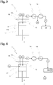
- FIG. 3 A possible embodiment of a disclosed as internal combustion engine disclosed advantageous drive device 1 is shown schematically in FIG FIG. 3 shown, using the example of a piston engine with a cylinder.
- the illustrated internal combustion engine 1 has a cylinder 111 and a piston 112 arranged movably therein, which together form a closed combustion chamber 11.
- oxygen 22 is introduced into the expanding combustion chamber 11 in a first cycle.
- the oxygen 22 is compressed in a second cycle, and at the end of the second cycle with a supply device 18, the fuel 20 is introduced into the combustion chamber 11 and burned.
- the expanding combustion gases 21 perform mechanical work
- the partially expanded combustion gases 21 are removed from the combustion chamber 11 by a venting device 12, not shown.
- the residual gas, which consists essentially only of carbon dioxide 24 and optionally residual amounts of carbon monoxide and unreacted fuels is compressed in a series-arranged compressor 14, and in a memory 15, in the simplest case a pressure vessel, pumped.
- the condensation stage 13 prior to compression 14 reduces the undesirable formation of condensed water droplets in the compressor 14.
- the illustrated disclosed advantageous internal combustion engine 1 has no emissions. Since the disclosed advantageous device is not operated with air or similar mixtures, no air-specific pollutants such as nitrogen oxides can arise. The water produced during combustion is unproblematic and can be separated. The carbon dioxide and other residual gases will be collected in memory 15 and stored for further use. Unburned portions of the fuel either condense with the water and are separated or are compressed together with the carbon dioxide.
- sulfur and phosphorus can also be present in the operating materials for a disclosed advantageous drive device.
- the sulfur may react with sulfur dioxide and sulfur trioxide in the oxidation reaction, which in turn reacts with the water to form sulfurous acid and sulfurous acid.
- sulfur dioxide and sulfur trioxide in the oxidation reaction, which in turn reacts with the water to form sulfurous acid and sulfurous acid.
- These corrosive pollutants can be condensed out with the water, separated and disposed of. The same applies to phosphorus-containing pollutants and any fine particulate matter that may arise.
- FIG. 4 Another possible embodiment of a disclosed as internal combustion engine disclosed advantageous drive device 1 is shown schematically in FIG. 4 shown.
- 17 water is introduced into the combustion chamber 11 by a feed device only schematically shown. This is preferably done so that during or after the combustion reaction, a certain amount of water, liquid or vapor, is injected into the combustion chamber and finely distributed. This water is heated by the heat of combustion, whereby the total gas volume in the combustion chamber 11 increases, and thus also the available for the performance of the mechanical work gas pressure or gas volume. Accordingly, the amount of fuel can then be reduced while the power remains the same.
- water can also be introduced into the product gas stream 21 when it has left the combustion chamber 11.
- water can also be introduced into the product gas stream 21 when it has left the combustion chamber 11.
- the amount of water and the timing of the injection are matched with the supply of fuel 21 and oxygen 22 so that the combustion reaction can take place efficiently.
- the resulting temperature during the oxidation reaction is substantially such that the highest possible thermodynamic efficiency of the heat engine is achieved.
- the greater the amount of water used the lower the relative proportion of carbon dioxide in the reaction gases, which reduces the amount of gas remaining to be compressed after condensation of the water.
- the combustion gases 21 are first compressed in a compressor 14, before they are subsequently cooled in the heat exchanger 13.
- the water 23 remains in the gas mixture 21, and collects in liquid form in the pressure vessel 15. With the regular emptying of the carbon dioxide 24 and the water 23 can be discharged at the same time.
- FIG. 4 shown variant is also with the internal combustion engine 1 without water injection FIG. 3 combinable, and vice versa, and can be generally used for a disclosed advantageous drive device 1.
- the energy required for the operation of the compressor of a disclosed advantageous drive device 1 is advantageously generated by the disclosed advantageous drive device itself.
- the achievable efficiency of the disclosed advantageous drive device decreases, but at the same time the freedom from emissions of said drive device is achieved.
- the achievable performance with the same engine dimensioning is greater, which compensates for the loss of power again.
- the compressor can be operated for example via a suitable transmission directly to the crankshaft of a piston internal combustion engine.
- the compressor can sit directly on the same shaft.
- the product gases can then be condensed directly subsequent to the expansion process and the remaining flow can be compressed.
- the product gases are already precompressed after combustion at the third clock within the combustion chamber, and only then discharged through the venting device 12.
- the downstream compressor 14 may also be omitted.
- Such an embodiment is also possible as a two-stroke variant, because the new loading of the combustion chamber with reaction mixture (fuel 20, oxygen 22, water 23) can be done very quickly in a disclosed advantageous drive device.
- reaction mixture fuel 20, oxygen 22, water 23
- a second upstroke the combustion gases are precompressed and exhausted from the combustor towards the end of the cycle.
- the gaseous oxygen may be injected into the combustion chamber under high pressure at the end of the upstroke because comparatively little oxygen is needed for a complete combustion reaction and water is present as an additional expansion agent.
- the liquid fuel 20 and the water 23 as expansion means can be injected in any case very quickly and under high pressure in the combustion chamber.
- the energy consumption for the compressor can be optimized by a suitable combination with one or more heat exchangers or cooling elements, in which the gas volume can be reduced by emitting heat energy of the reaction gases to an internal or external heat sink.
- a disclosed advantageous drive device 1 as a heat engine with external combustion, for example as a steam engine or steam turbine or as a Sterling engine.
- FIG. 5 A vehicle powered by a disclosed advantageous drive device 1 as an example of a disclosed advantageous mobile machine 3 is shown in FIG FIG. 5 shown schematically.
- a disclosed as an internal combustion engine disclosed advantageous drive device 1 is either used directly as a drive unit, or is alternatively operated constantly at an ideal speed range, with a generator power for an electric drive unit is generated. If the disclosed advantageous drive device 1 configured as a fuel cell system, also serves as an electric motor as a drive unit.
- the vehicle 3 has a tank 31 for the liquid or gaseous fuel 20, as well as a pressure tank 32 for the oxygen 22.
- the gas storage 15 for the carbon dioxide is advantageously also designed as a pressure tank 15.
- a disclosed advantageous drive device 1 is particularly suitable for less weight-sensitive vehicles, such as land and water vehicles, in particular vehicles in city traffic or ships and larger boats. Depending on the size of the vehicle, it is also possible to carry out the production of oxygen on site, whereby the pressure tank 32 serves only as a temporary storage and can be designed correspondingly smaller.
- FIG. 5 Not shown in FIG. 5 is a possible reservoir for the water 23. However, such can be made relatively small.
- the condensed water obtained in the aftertreatment of the combustion gases can be recycled, whereby the effective water consumption and thus the size of the necessary reservoir is even smaller.
- FIG. 5 The vehicle 3 is loaded to a correspondingly equipped refueling system 41 with liquid or gaseous fuel 20, as well as with compressed oxygen 22. At the same time the collected gas in the store 15 Carbon dioxide 24 returned to a corresponding gas storage of the refueling system 41.
- the refueling system 41 forms with a fuel production plant 6, as described in the European application no. 09176684.0 (EP 2325288 A1 ) of the applicant discloses a closed circuit.
- the plant 6 produces liquid or gaseous hydrocarbon fuels 20 from carbonaceous starting materials 27. These are transported by suitable means to the refueling plant 41.
- the carbon dioxide 24 in turn, optionally with proportions of carbon monoxide and unreacted fuel, which has been returned from the vehicle 3 in the refueling unit 41, is transported via suitable means to the system 6, where it is fed into the closed circuit of the system 6.
- a refueling system 41 for example, for public bus companies in a city.
- the buses fueled exclusively in the refueling of the operation, so that with a relatively small number refueling refueling installations 41 many vehicles 3 can be achieved. This leads to lower investment costs in a corresponding overall system.
- FIG. 6 shows a possible embodiment of such a supply network.
- the system has two annular networks.
- a first supply network 51 gaseous fuel 20 is fed from a closed loop production plant 6. From this network 51, various refueling installations 41 receive the gaseous fuels. Also connected to the network 51 is an example of a power plant 43, in which by means of a disclosed advantageous drive device, a power generator is operated, and a first latch 71st
- a second return network 52 is present, in which the refueling installations 41 and the power plant 43 feed the resulting carbon dioxide 24. This is in turn conveyed back to the production plant 6.
- a second latch 72 serves to increase the capacity of the second network.
- an end bearing 44 for carbon dioxide is also shown by way of example. Carbon dioxide is diverted from the second network and pumped under pressure into an exhausted Erdöllager, where it then remains permanently.
- a disclosed advantageous drive device is connected directly to such a disclosed advantageous supply system 5, then a fuel tank 31 and / or gas storage 15 for the carbon dioxide can be completely dispensed with, since the fixed line system assumes this function. This is for example in the power production plant 43 in FIG. 6 the case.
Landscapes
- Engineering & Computer Science (AREA)
- Mechanical Engineering (AREA)
- General Engineering & Computer Science (AREA)
- Chemical & Material Sciences (AREA)
- Combustion & Propulsion (AREA)
- Engine Equipment That Uses Special Cycles (AREA)
- Organic Low-Molecular-Weight Compounds And Preparation Thereof (AREA)
- Separation By Low-Temperature Treatments (AREA)
- Loading And Unloading Of Fuel Tanks Or Ships (AREA)
- Filling Or Discharging Of Gas Storage Vessels (AREA)
- Fertilizing (AREA)
Priority Applications (74)
| Application Number | Priority Date | Filing Date | Title |
|---|---|---|---|
| EP10151481.8A EP2348254B1 (de) | 2010-01-22 | 2010-01-22 | Betankungsanlage für ein mobile Maschine |
| LTEP10151481.8T LT2348254T (lt) | 2010-01-22 | 2010-01-22 | Mobiliosios mašinos degalų papildymo sistema |
| PT101514818T PT2348254T (pt) | 2010-01-22 | 2010-01-22 | Sistema de abastecimento de combustível para uma máquina móvel |
| TR2018/02811T TR201802811T4 (tr) | 2010-01-22 | 2010-01-22 | Hareketli Bir Makine için Yakıt Doldurma Sistemi. |
| NO10151481A NO2348254T3 (hu) | 2010-01-22 | 2010-01-22 | |
| SI201031643T SI2348254T1 (en) | 2010-01-22 | 2010-01-22 | Filling machine for mobile machine |
| PL10151481T PL2348254T3 (pl) | 2010-01-22 | 2010-01-22 | Instalacja do tankowania ruchomej maszyny |
| HUE10151481A HUE036115T2 (hu) | 2010-01-22 | 2010-01-22 | Tankoló berendezés mobil gép számára |
| ES10151481.8T ES2660186T3 (es) | 2010-01-22 | 2010-01-22 | Instalación de repostaje para una máquina móvil |
| DK10151481.8T DK2348254T3 (en) | 2010-01-22 | 2010-01-22 | Refueling system for a mobile machine |
| UY0001033038A UY33038A (es) | 2009-11-20 | 2010-11-18 | Uso termico y quimico de sustancias cabonaceas en particular para la generacion de energia sin emisiones |
| LT10777041T LT2501786T (lt) | 2009-11-20 | 2010-11-19 | Medžiagų, kurių sudėtyje yra anglies, terminis-cheminis utilizavimas, konkrečiai, skirtas energijos generavimui be teršalų išmetimo |
| TW099139890A TWI522454B (zh) | 2009-11-20 | 2010-11-19 | 特別用於無排放能源產生之含碳物質之熱及化學利用 |
| EA201270637A EA024594B9 (ru) | 2009-11-20 | 2010-11-19 | Термическая и химическая утилизация углеродсодержащих материалов, в частности для генерации энергии без вредных выбросов |
| AU2010320871A AU2010320871B2 (en) | 2009-11-20 | 2010-11-19 | Thermal-chemical utilization of carbon-containing materials, in particular for the emission-free generation of energy |
| DK10777041T DK2501786T3 (da) | 2009-11-20 | 2010-11-19 | Termisk-kemisk udnyttelse af carbonholdige materialer, især til emissionsfri frembringelse af energi |
| PCT/EP2010/067847 WO2011061299A1 (de) | 2009-11-20 | 2010-11-19 | Thermisch-chemische verwertung von kohlenstoffhaltigen materialien, insbesondere zur emissionsfreien erzeugung von energie |
| PT107770414T PT2501786T (pt) | 2009-11-20 | 2010-11-19 | ¿utilização termoquímica de materiais carbonáceos, em particular para a geração de energia sem emissões |
| SI201031947T SI2501786T1 (sl) | 2009-11-20 | 2010-11-19 | Toplotno-kemično izkoriščanje materialov, ki vsebujejo ogljik, zlasti za pridobivanje energije brez emisij |
| RS20191418A RS59514B1 (sr) | 2009-11-20 | 2010-11-19 | Toplotno i hemijsko iskorišćavanje ugljeničnih materijala, naročito za bezemisionu proizvodnju energije |
| ARP100104282A AR079079A1 (es) | 2009-11-20 | 2010-11-19 | Uso termico y quimico de sustancias carbonaceas en particular para la generacion de energia sin emisiones |
| CA2780856A CA2780856C (en) | 2009-11-20 | 2010-11-19 | Thermal and chemical utilization of carbonaceous materials, in particular for emission-free generation of energy |
| EP19190005.9A EP3594313A1 (de) | 2009-11-20 | 2010-11-19 | Thermisch-chemische verwertung von kohlenstoffhaltigen materialien, insbesondere zur emissionsfreien erzeugung von energie |
| GEAP201012757A GEP20146206B (en) | 2009-11-20 | 2010-11-19 | Thermal-chemical utilization of carbon-containing materials, in particular for the emission-free generation of energy |
| MX2012005713A MX2012005713A (es) | 2009-11-20 | 2010-11-19 | Uso termico y quimico de materiales carbonosos, en particular para la generacion de energia libre de emisiones. |
| AP2012006319A AP3292A (en) | 2009-11-20 | 2010-11-19 | Thermal-chemical utilization of carbon-containing materials, in particular for the emission-free generation of energy |
| ES10777041T ES2758543T3 (es) | 2009-11-20 | 2010-11-19 | Aprovechamiento termoquímico de materiales carbonosos, en particular para la generación de energía sin emisiones |
| BR112012011891A BR112012011891B1 (pt) | 2009-11-20 | 2010-11-19 | utilização térmica e química de materiais carbonáceos em particular para geração de energia livre de emissão |
| SG10201407559RA SG10201407559RA (en) | 2009-11-20 | 2010-11-19 | Thermal-chemical utilization of carbon-containing materials, in particular for the emission-free generation of energy |
| MYPI2012002196A MY158603A (en) | 2009-11-20 | 2010-11-19 | Thermal and chemical utilization of carbonaceous materials, in particular for emisson-free generation of energy |
| PL10777041T PL2501786T3 (pl) | 2009-11-20 | 2010-11-19 | Termiczno-chemiczne użytkowanie materiałów zawierających węgiel, w szczególności do bezemisyjnego wytwarzania energii |
| CN201080052571.XA CN102762697B (zh) | 2009-11-20 | 2010-11-19 | 碳质材料的热化学利用,特别是用于零排放地产生能量 |
| US13/509,883 US10450520B2 (en) | 2009-11-20 | 2010-11-19 | Thermal and chemical utilization of carbonaceous materials, in particular for emission-free generation of energy |
| EP10777041.4A EP2501786B1 (de) | 2009-11-20 | 2010-11-19 | Thermisch-chemische verwertung von kohlenstoffhaltigen materialien, insbesondere zur emissionsfreien erzeugung von energie |
| KR1020127015840A KR101824267B1 (ko) | 2009-11-20 | 2010-11-19 | 특히 배출물이 없는 에너지 발생을 위한 탄소 함유 물질의 열적-화학적 이용 |
| HUE10777041A HUE047176T2 (hu) | 2009-11-20 | 2010-11-19 | Széntartalmú anyagok termokémiai hasznosítása, különösen kibocsátásmentes energiatermeléshez |
| MEP-2019-308A ME03549B (me) | 2009-11-20 | 2010-11-19 | Toplotno i hemijsko iskorišćavanje ugljeničnih materijala, naročiтo za bezemisionu proizvodnju energije |
| NZ600722A NZ600722A (en) | 2009-11-20 | 2010-11-19 | Thermal and chemical utilization of carbonaceous materials, in particular for emission-free generation of energy |
| MA34974A MA33889B1 (fr) | 2009-11-20 | 2010-11-19 | Conversion thermochimique de matériaux carbonés, en particulier pour la production d'énergie sans émissions |
| JP2012539341A JP5791054B2 (ja) | 2009-11-20 | 2010-11-19 | 特に排出のないエネルギー生成のための炭素含有物質の熱化学的利用 |
| TW100101391A TWI600825B (zh) | 2010-01-22 | 2011-01-14 | 用來執行機械功與生產電能和熱能之無排放裝置和方法 |
| ARP110100186A AR079947A1 (es) | 2010-01-22 | 2011-01-19 | Dispositivo sin emisiones y procedimientos para realizar trabajo mecanico y producir energia electrica y termica |
| EP20181575.0A EP3789474A1 (de) | 2010-01-22 | 2011-01-20 | Emissionsfreie vorrichtungen und verfahren zur verrichtung mechanischer arbeit und zur erzeugung von elektrischer und thermischer energie |
| LTEP11701082.7T LT2526177T (lt) | 2010-01-22 | 2011-01-20 | Aplinkos neteršiantys įrenginiai mechaniniam darbui atlikti |
| SI201131917T SI2526177T1 (sl) | 2010-01-22 | 2011-01-20 | Brezemisijske naprave za opravljanje mehanskega dela |
| EA201270678A EA201270678A1 (ru) | 2010-01-22 | 2011-01-20 | Устройства без выбросов и способ выполнения механической работы и выработки электрической и тепловой энергии |
| ES11701082T ES2819287T3 (es) | 2010-01-22 | 2011-01-20 | Dispositivos libres de emisiones para la ejecución de trabajo mecánico |
| US13/522,914 US10072841B2 (en) | 2010-01-22 | 2011-01-20 | Emission-free devices and method for performing mechanical work and for generating electrical and thermal energy |
| PCT/EP2011/050788 WO2011089200A2 (de) | 2010-01-22 | 2011-01-20 | Emissionsfreie vorrichtungen und verfahren zur verrichtung mechanischer arbeit und zur erzeugung von elektrischer und thermischer energie |
| HUE11701082A HUE051957T2 (hu) | 2010-01-22 | 2011-01-20 | Kibocsátásmentes eszköz mechanikai munka végzésére |
| PL11701082T PL2526177T3 (pl) | 2010-01-22 | 2011-01-20 | Bezemisyjne urządzenia do wykonywania pracy mechanicznej |
| RS20201078A RS60896B1 (sr) | 2010-01-22 | 2011-01-20 | Uređaji za izvođenje mehaničkog rada bez emisije |
| DK11701082.7T DK2526177T3 (da) | 2010-01-22 | 2011-01-20 | Emissionsfrie indretninger til udførelse af mekanisk arbejde |
| EP11701082.7A EP2526177B1 (de) | 2010-01-22 | 2011-01-20 | Emissionsfreie vorrichtungen zur verrichtung mechanischer arbeit |
| UY0001033197A UY33197A (es) | 2010-01-22 | 2011-01-20 | Dispositivos sin emisiones y procedimientos para realizar trabajo mecanico y producir energia electrica y mecanica |
| PT117010827T PT2526177T (pt) | 2010-01-22 | 2011-01-20 | Mecanismos isentos de emissões para a realização de trabalhos mecânicos |
| TNP2012000213A TN2012000213A1 (en) | 2009-11-20 | 2012-05-11 | Thermal and chemical utilization of carbonaceous materials, in particular for emission-free generation of energy |
| IL219746A IL219746A (en) | 2009-11-20 | 2012-05-13 | Thermal and chemical utilization of carbon-containing materials, especially to generate energy without emissions |
| CL2012001299A CL2012001299A1 (es) | 2009-11-20 | 2012-05-18 | Proceso e infraestructura para la generacion de energia y/o hidrocarburos libre de emisiones mediante el uso de materiales carbonosos, con etapas de pirolisis (p1), gasificacion (p2), y conversion fischer-tropsch (p3), que forman un ciclo cerrado, donde el gas de (p3) pasa a (p1) y/o (p2) y el gas de (p1) pasa a (p2) y/o (p3). |
| NI201200092A NI201200092A (es) | 2009-11-20 | 2012-05-18 | Uso térmico y químico de materiales carbonosos, en particular para la generación de energía libre de emisiones |
| HN2012001100A HN2012001100A (es) | 2009-11-20 | 2012-05-18 | Uso termico y quimico de materiales carbonosos, en particular para la generacion de energia libre de emisiones. |
| ECSP12011973 ECSP12011973A (es) | 2009-11-20 | 2012-06-14 | Uso térmico y químico de materiales carbonosos, en particular para la generación de energía libre de emisiones |
| CO12100242A CO6541590A2 (es) | 2009-11-20 | 2012-06-14 | Uso termico y quimico de materiales carbonosos, en particular para la generacion de energia libre de emisiones |
| ZA2012/04529A ZA201204529B (en) | 2009-11-20 | 2012-06-19 | Thermal-chemical utilization of carbon-containing materials,in particular for the emission-free generation of energy |
| CY20181100230T CY1120234T1 (el) | 2010-01-22 | 2018-02-26 | Εγκατασταση ανεφοδιασμου σε καυσιμο για μια κινητη μηχανη |
| HRP20180354TT HRP20180354T1 (hr) | 2010-01-22 | 2018-02-27 | Sustav za punjenje gorivom za mobilni stroj |
| US16/125,014 US11397004B2 (en) | 2010-01-22 | 2018-09-07 | Emission-free devices and method for performing mechanical work and for generating electrical and thermal energy |
| US16/567,326 US10844302B2 (en) | 2009-11-20 | 2019-09-11 | Thermal and chemical utilization of carbonaceous materials, in particular for emission-free generation of energy |
| HRP20191988TT HRP20191988T1 (hr) | 2009-11-20 | 2019-11-04 | Termokemijska upotreba materijala koji sadrže ugljik, osobito kod proizvodnje energije bez emisije |
| CY20191101158T CY1122410T1 (el) | 2009-11-20 | 2019-11-06 | Θερμοχημικη αξιοποιηση ανθρακουχων υλικων, ιδιως για παραγωγη ενεργειας ανευ εκπομπων |
| CY20201100863T CY1123340T1 (el) | 2010-01-22 | 2020-09-11 | Διαταξεις και μεθοδοι ανευ εκπομπων για εκτελεση μηχανικου εργου και για παραγωγη ηλεκτρικης και θερμικης ενεργειας |
| HRP20201464TT HRP20201464T1 (hr) | 2010-01-22 | 2020-09-14 | Uređaji bez emisije za obavljanje mehaničkog rada |
| US17/076,325 US20210032553A1 (en) | 2009-11-20 | 2020-10-21 | Thermal and chemical utilization of carbonaceous materials, in particular for emission-free generation of energy |
| US17/871,192 US20230018213A1 (en) | 2010-01-22 | 2022-07-22 | Emission-free devices and method for performing mechanical work and for generating electrical and thermal energy |
Applications Claiming Priority (1)
| Application Number | Priority Date | Filing Date | Title |
|---|---|---|---|
| EP10151481.8A EP2348254B1 (de) | 2010-01-22 | 2010-01-22 | Betankungsanlage für ein mobile Maschine |
Publications (2)
| Publication Number | Publication Date |
|---|---|
| EP2348254A1 EP2348254A1 (de) | 2011-07-27 |
| EP2348254B1 true EP2348254B1 (de) | 2017-11-29 |
Family
ID=42244888
Family Applications (1)
| Application Number | Title | Priority Date | Filing Date |
|---|---|---|---|
| EP10151481.8A Active EP2348254B1 (de) | 2009-11-20 | 2010-01-22 | Betankungsanlage für ein mobile Maschine |
Country Status (12)
| Country | Link |
|---|---|
| EP (1) | EP2348254B1 (hu) |
| CY (1) | CY1120234T1 (hu) |
| DK (1) | DK2348254T3 (hu) |
| ES (1) | ES2660186T3 (hu) |
| HR (1) | HRP20180354T1 (hu) |
| HU (1) | HUE036115T2 (hu) |
| LT (1) | LT2348254T (hu) |
| NO (1) | NO2348254T3 (hu) |
| PL (1) | PL2348254T3 (hu) |
| PT (1) | PT2348254T (hu) |
| SI (1) | SI2348254T1 (hu) |
| TR (1) | TR201802811T4 (hu) |
Families Citing this family (4)
| Publication number | Priority date | Publication date | Assignee | Title |
|---|---|---|---|---|
| AT511941B1 (de) * | 2012-05-14 | 2013-04-15 | Mair Christian | Betriebsstoffversorgungssystem für Fahrzeuge mit Kohlendioxidspeicherung |
| PL399500A1 (pl) | 2012-06-12 | 2013-12-23 | Dagas Spólka Z Ograniczona Odpowiedzialnoscia | Sposób prowadzenia procesu pirolizy odpadowych tworzyw sztucznych i/lub odpadów gumowych i/lub odpadów organicznych oraz instalacja do realizacji tego sposobu |
| IT202100033053A1 (it) | 2021-12-30 | 2023-06-30 | Versalis Spa | Processo di pirolisi per la produzione di un olio di pirolisi adatto al riciclo a ciclo chiuso (“closed loop recycling”), relativo apparato, prodotto ed uso del medesimo |
| IT202100033059A1 (it) | 2021-12-30 | 2023-06-30 | Versalis Spa | Metodo per monitorare un parametro di controllo su un materiale sostanzialmente plastico, relativo apparato e processo di pirolisi che impiega detto metodo |
Family Cites Families (7)
| Publication number | Priority date | Publication date | Assignee | Title |
|---|---|---|---|---|
| DE3433602A1 (de) * | 1984-08-18 | 1986-02-27 | Horst 7447 Aichtal Jentzsch | Einrichtung zum absaugen und sammeln von gasen, insbesondere von kraftfahrzeug-auspuffgasen in einer montage- oder betriebshalle |
| DE19523109C2 (de) * | 1995-06-26 | 2001-10-11 | Daimler Chrysler Ag | Kraftfahrzeug mit Brennkraftmaschine und einem Stromerzeugungssystem |
| CA2271450A1 (en) | 1999-05-12 | 2000-11-12 | Stuart Energy Systems Inc. | Hydrogen fuel replenishment process and apparatus |
| AT4883U1 (de) | 2000-06-23 | 2001-12-27 | Hermeling Werner Dipl Ing | Mobile füllanlage für gasflaschen |
| NO320939B1 (no) * | 2002-12-10 | 2006-02-13 | Aker Kvaerner Engineering & Te | Fremgangsmate for eksosgassbehandling i brenselcellesystem basert pa oksider i fast form |
| US8087926B2 (en) * | 2005-12-28 | 2012-01-03 | Jupiter Oxygen Corporation | Oxy-fuel combustion with integrated pollution control |
| US20090297993A1 (en) * | 2008-05-30 | 2009-12-03 | Foster Wheeler Energia Oy | Method of and System For Generating Power By Oxyfuel Combustion |
-
2010
- 2010-01-22 DK DK10151481.8T patent/DK2348254T3/en active
- 2010-01-22 TR TR2018/02811T patent/TR201802811T4/tr unknown
- 2010-01-22 HU HUE10151481A patent/HUE036115T2/hu unknown
- 2010-01-22 ES ES10151481.8T patent/ES2660186T3/es active Active
- 2010-01-22 EP EP10151481.8A patent/EP2348254B1/de active Active
- 2010-01-22 NO NO10151481A patent/NO2348254T3/no unknown
- 2010-01-22 LT LTEP10151481.8T patent/LT2348254T/lt unknown
- 2010-01-22 PL PL10151481T patent/PL2348254T3/pl unknown
- 2010-01-22 PT PT101514818T patent/PT2348254T/pt unknown
- 2010-01-22 SI SI201031643T patent/SI2348254T1/en unknown
-
2018
- 2018-02-26 CY CY20181100230T patent/CY1120234T1/el unknown
- 2018-02-27 HR HRP20180354TT patent/HRP20180354T1/hr unknown
Non-Patent Citations (1)
| Title |
|---|
| None * |
Also Published As
| Publication number | Publication date |
|---|---|
| NO2348254T3 (hu) | 2018-04-28 |
| ES2660186T3 (es) | 2018-03-21 |
| LT2348254T (lt) | 2018-03-26 |
| PL2348254T3 (pl) | 2018-05-30 |
| HUE036115T2 (hu) | 2018-06-28 |
| DK2348254T3 (en) | 2018-02-05 |
| PT2348254T (pt) | 2018-02-26 |
| TR201802811T4 (tr) | 2018-03-21 |
| CY1120234T1 (el) | 2019-07-10 |
| HRP20180354T1 (hr) | 2018-04-06 |
| SI2348254T1 (en) | 2018-04-30 |
| EP2348254A1 (de) | 2011-07-27 |
Similar Documents
| Publication | Publication Date | Title |
|---|---|---|
| EP2501786B1 (de) | Thermisch-chemische verwertung von kohlenstoffhaltigen materialien, insbesondere zur emissionsfreien erzeugung von energie | |
| DE2738638A1 (de) | Mit wasserstoff betriebene verbrennungskraftmaschinen sowie verfahren zum betreiben dieser | |
| EP4028489B1 (de) | Vorrichtung und verfahren umfassend zwei teilsysteme zur nutzung kohlenstoffbasierter kraftstoffe in verbrennungskraftmaschinen im kreislaufbetrieb unter wiederverwendung des anfallenden oxidationsprodukts und der mitführung eines oxidationsmittels auf dem verkehrsmittel | |
| EP2348254B1 (de) | Betankungsanlage für ein mobile Maschine | |
| US20230018213A1 (en) | Emission-free devices and method for performing mechanical work and for generating electrical and thermal energy | |
| WO2012045743A1 (de) | Verfahren zur bereitstellung und zum einsetzen eines alkohols und verwendung des alkohols zur wirkungsgrad- und leistungssteigerung einer verbrennungskraftmaschine | |
| WO2013034130A2 (de) | Ökologische sequestrierung von kohlendioxid / vermehrung der durch biomasse erzielbaren bioenergie | |
| DE102017210324A1 (de) | Energiewandlungseinrichtung zur Umwandlung elektrischer Energie in chemische Energie, Stromnetz mit einer solchen Energiewandlungseinrichtung, und Verfahren zum Betreiben einer solchen Energiewandlungseinrichtung | |
| DE102012105736A1 (de) | Verfahren zur Speicherung von Elektroenergie | |
| DE102010029972A1 (de) | Verbrennungsmotor für Wasserstoff mit hohem Wirkungsgrad | |
| WO2021191116A1 (de) | Co2-neutraler flüssigkraftstoff | |
| EP2325287A1 (de) | Emissionsfreies Kraftwerk zur Erzeugung von elektrischer und mechanischer Energie | |
| EP2348253A1 (de) | Emissionsfreies Verfahren zur Verrichtung mechanischer Arbeit | |
| WO2017050459A1 (de) | Dampfturbinenkraftwerk mit wasserstoffverbrennung unter einbindung einer vergasungseinrichtung | |
| DE202008008567U1 (de) | Kompakt Energiepaket für Fahrzeuge bestehend aus der Kombination einer Gasturbine gekoppelt mit einem oder mehreren Generatoren | |
| DE102016008835A1 (de) | Integrierte Abgasverwertungs - und Kraftstoffvergasungsanlage für Verbrennungsmotoren aller Art | |
| DE102016204139B4 (de) | Verfahren zum Betreiben einer Brennkraftmaschineneinrichtung und Brennkraftmaschineneinrichtung | |
| EP3022277B1 (de) | Verfahren zur nutzung von biomasse zur erzeugung von elektrischer energie und wärmebereitstellung durch pyrolyse; vergasung und verbrennung und zur umwandlung von wärmeenergie in elektrische energie | |
| WO2013171107A2 (de) | Betriebsstoffversorgungssystem für fahrzeuge mit kohlendioxidspeicherung | |
| EP3081289B1 (en) | A combustion process for solid, liquid or gaseous hydrocarbon (hc) raw materials in a thermal engine, thermal engine and system for producing energy from hydrocarbon (hc) materials | |
| DE202017003690U1 (de) | Wasserstoff-Dampf-Kraft-Werk | |
| DE102017205764A1 (de) | Fahrzeug, insbesondere Kraftfahrzeug, sowie Elektrolyseur | |
| WO2002057105A1 (de) | Antriebsvorrichtung, insbesondere für ein fahrzeug, mit einem verbrennungsmotor und wenigstens einem elektrischen stromerzeuger__ | |
| DE102021127949A1 (de) | Antriebsanordnung für ein Mobil, Mobil mit der Antriebsanordnung sowie Verfahren zur Abgasreinigung bei Antriebsanordnung und/oder bei dem Mobil | |
| EA040719B1 (ru) | Устройства без выбросов и способ выполнения механической работы и выработки электрической и тепловой энергии |
Legal Events
| Date | Code | Title | Description |
|---|---|---|---|
| PUAI | Public reference made under article 153(3) epc to a published international application that has entered the european phase |
Free format text: ORIGINAL CODE: 0009012 |
|
| AK | Designated contracting states |
Kind code of ref document: A1 Designated state(s): AT BE BG CH CY CZ DE DK EE ES FI FR GB GR HR HU IE IS IT LI LT LU LV MC MK MT NL NO PL PT RO SE SI SK SM TR |
|
| AX | Request for extension of the european patent |
Extension state: AL BA RS |
|
| 17P | Request for examination filed |
Effective date: 20120127 |
|
| REG | Reference to a national code |
Ref country code: HK Ref legal event code: DE Ref document number: 1160505 Country of ref document: HK |
|
| RIC1 | Information provided on ipc code assigned before grant |
Ipc: F23J 15/06 20060101ALI20151222BHEP Ipc: F23L 7/00 20060101AFI20151222BHEP |
|
| RIC1 | Information provided on ipc code assigned before grant |
Ipc: F23J 15/06 20060101AFI20160113BHEP Ipc: F23L 7/00 20060101ALI20160113BHEP Ipc: B67D 7/00 20100101ALI20160113BHEP |
|
| RAP1 | Party data changed (applicant data changed or rights of an application transferred) |
Owner name: RV LIZENZ AG |
|
| GRAP | Despatch of communication of intention to grant a patent |
Free format text: ORIGINAL CODE: EPIDOSNIGR1 |
|
| INTG | Intention to grant announced |
Effective date: 20170207 |
|
| GRAJ | Information related to disapproval of communication of intention to grant by the applicant or resumption of examination proceedings by the epo deleted |
Free format text: ORIGINAL CODE: EPIDOSDIGR1 |
|
| GRAP | Despatch of communication of intention to grant a patent |
Free format text: ORIGINAL CODE: EPIDOSNIGR1 |
|
| INTC | Intention to grant announced (deleted) | ||
| INTG | Intention to grant announced |
Effective date: 20170626 |
|
| GRAS | Grant fee paid |
Free format text: ORIGINAL CODE: EPIDOSNIGR3 |
|
| GRAA | (expected) grant |
Free format text: ORIGINAL CODE: 0009210 |
|
| AK | Designated contracting states |
Kind code of ref document: B1 Designated state(s): AT BE BG CH CY CZ DE DK EE ES FI FR GB GR HR HU IE IS IT LI LT LU LV MC MK MT NL NO PL PT RO SE SI SK SM TR |
|
| REG | Reference to a national code |
Ref country code: CH Ref legal event code: EP |
|
| REG | Reference to a national code |
Ref country code: AT Ref legal event code: REF Ref document number: 950730 Country of ref document: AT Kind code of ref document: T Effective date: 20171215 |
|
| REG | Reference to a national code |
Ref country code: IE Ref legal event code: FG4D Free format text: LANGUAGE OF EP DOCUMENT: GERMAN |
|
| REG | Reference to a national code |
Ref country code: DE Ref legal event code: R096 Ref document number: 502010014416 Country of ref document: DE |
|
| REG | Reference to a national code |
Ref country code: FR Ref legal event code: PLFP Year of fee payment: 9 |
|
| REG | Reference to a national code |
Ref country code: CH Ref legal event code: NV Representative=s name: CMSRK RENTSCH KAELIN AG, CH |
|
| REG | Reference to a national code |
Ref country code: DK Ref legal event code: T3 Effective date: 20180131 |
|
| REG | Reference to a national code |
Ref country code: PT Ref legal event code: SC4A Ref document number: 2348254 Country of ref document: PT Date of ref document: 20180226 Kind code of ref document: T Free format text: AVAILABILITY OF NATIONAL TRANSLATION Effective date: 20180219 Ref country code: RO Ref legal event code: EPE |
|
| REG | Reference to a national code |
Ref country code: HR Ref legal event code: TUEP Ref document number: P20180354 Country of ref document: HR |
|
| REG | Reference to a national code |
Ref country code: NL Ref legal event code: FP |
|
| REG | Reference to a national code |
Ref country code: SE Ref legal event code: TRGR |
|
| REG | Reference to a national code |
Ref country code: ES Ref legal event code: FG2A Ref document number: 2660186 Country of ref document: ES Kind code of ref document: T3 Effective date: 20180321 |
|
| REG | Reference to a national code |
Ref country code: HR Ref legal event code: T1PR Ref document number: P20180354 Country of ref document: HR |
|
| REG | Reference to a national code |
Ref country code: EE Ref legal event code: FG4A Ref document number: E015119 Country of ref document: EE Effective date: 20180227 |
|
| REG | Reference to a national code |
Ref country code: NO Ref legal event code: T2 Effective date: 20171129 |
|
| REG | Reference to a national code |
Ref country code: HU Ref legal event code: AG4A Ref document number: E036115 Country of ref document: HU |
|
| REG | Reference to a national code |
Ref country code: GR Ref legal event code: EP Ref document number: 20180400551 Country of ref document: GR Effective date: 20180627 |
|
| REG | Reference to a national code |
Ref country code: HK Ref legal event code: GR Ref document number: 1160505 Country of ref document: HK |
|
| REG | Reference to a national code |
Ref country code: DE Ref legal event code: R097 Ref document number: 502010014416 Country of ref document: DE |
|
| PG25 | Lapsed in a contracting state [announced via postgrant information from national office to epo] |
Ref country code: SM Free format text: LAPSE BECAUSE OF FAILURE TO SUBMIT A TRANSLATION OF THE DESCRIPTION OR TO PAY THE FEE WITHIN THE PRESCRIBED TIME-LIMIT Effective date: 20171129 |
|
| PG25 | Lapsed in a contracting state [announced via postgrant information from national office to epo] |
Ref country code: MT Free format text: LAPSE BECAUSE OF FAILURE TO SUBMIT A TRANSLATION OF THE DESCRIPTION OR TO PAY THE FEE WITHIN THE PRESCRIBED TIME-LIMIT Effective date: 20171129 |
|
| PLBE | No opposition filed within time limit |
Free format text: ORIGINAL CODE: 0009261 |
|
| STAA | Information on the status of an ep patent application or granted ep patent |
Free format text: STATUS: NO OPPOSITION FILED WITHIN TIME LIMIT |
|
| 26N | No opposition filed |
Effective date: 20180830 |
|
| REG | Reference to a national code |
Ref country code: HR Ref legal event code: ODRP Ref document number: P20180354 Country of ref document: HR Payment date: 20190111 Year of fee payment: 10 |
|
| REG | Reference to a national code |
Ref country code: CH Ref legal event code: PFA Owner name: RV LIZENZ AG, CH Free format text: FORMER OWNER: RV LIZENZ AG, CH |
|
| REG | Reference to a national code |
Ref country code: HR Ref legal event code: ODRP Ref document number: P20180354 Country of ref document: HR Payment date: 20200121 Year of fee payment: 11 |
|
| REG | Reference to a national code |
Ref country code: HR Ref legal event code: ODRP Ref document number: P20180354 Country of ref document: HR Payment date: 20210406 Year of fee payment: 12 |
|
| PGFP | Annual fee paid to national office [announced via postgrant information from national office to epo] |
Ref country code: IS Payment date: 20210311 Year of fee payment: 12 |
|
| REG | Reference to a national code |
Ref country code: EE Ref legal event code: HC1A Ref document number: E015119 Country of ref document: EE |
|
| PGFP | Annual fee paid to national office [announced via postgrant information from national office to epo] |
Ref country code: MC Payment date: 20210414 Year of fee payment: 12 Ref country code: CY Payment date: 20210413 Year of fee payment: 12 |
|
| REG | Reference to a national code |
Ref country code: HR Ref legal event code: ODRP Ref document number: P20180354 Country of ref document: HR Payment date: 20220216 Year of fee payment: 13 |
|
| PGFP | Annual fee paid to national office [announced via postgrant information from national office to epo] |
Ref country code: LT Payment date: 20220211 Year of fee payment: 13 Ref country code: IE Payment date: 20220216 Year of fee payment: 13 Ref country code: HU Payment date: 20220213 Year of fee payment: 13 Ref country code: GB Payment date: 20220223 Year of fee payment: 13 Ref country code: FI Payment date: 20220217 Year of fee payment: 13 Ref country code: DK Payment date: 20220215 Year of fee payment: 13 Ref country code: DE Payment date: 20220217 Year of fee payment: 13 Ref country code: CH Payment date: 20220216 Year of fee payment: 13 Ref country code: BG Payment date: 20220217 Year of fee payment: 13 Ref country code: AT Payment date: 20220217 Year of fee payment: 13 |
|
| PGFP | Annual fee paid to national office [announced via postgrant information from national office to epo] |
Ref country code: TR Payment date: 20220210 Year of fee payment: 13 Ref country code: SK Payment date: 20220221 Year of fee payment: 13 Ref country code: SE Payment date: 20220216 Year of fee payment: 13 Ref country code: RO Payment date: 20220210 Year of fee payment: 13 Ref country code: PT Payment date: 20220210 Year of fee payment: 13 Ref country code: PL Payment date: 20220211 Year of fee payment: 13 Ref country code: NO Payment date: 20220214 Year of fee payment: 13 Ref country code: NL Payment date: 20220203 Year of fee payment: 13 Ref country code: MK Payment date: 20220211 Year of fee payment: 13 Ref country code: LV Payment date: 20220221 Year of fee payment: 13 Ref country code: LU Payment date: 20220216 Year of fee payment: 13 Ref country code: IT Payment date: 20220218 Year of fee payment: 13 Ref country code: HR Payment date: 20220216 Year of fee payment: 13 Ref country code: GR Payment date: 20220221 Year of fee payment: 13 Ref country code: FR Payment date: 20220216 Year of fee payment: 13 Ref country code: ES Payment date: 20220325 Year of fee payment: 13 Ref country code: EE Payment date: 20220221 Year of fee payment: 13 Ref country code: CZ Payment date: 20220222 Year of fee payment: 13 Ref country code: BE Payment date: 20220216 Year of fee payment: 13 |
|
| PGFP | Annual fee paid to national office [announced via postgrant information from national office to epo] |
Ref country code: SI Payment date: 20220215 Year of fee payment: 13 |
|
| PG25 | Lapsed in a contracting state [announced via postgrant information from national office to epo] |
Ref country code: MC Free format text: LAPSE BECAUSE OF NON-PAYMENT OF DUE FEES Effective date: 20220131 |
|
| PG25 | Lapsed in a contracting state [announced via postgrant information from national office to epo] |
Ref country code: CY Free format text: LAPSE BECAUSE OF NON-PAYMENT OF DUE FEES Effective date: 20220122 |
|
| REG | Reference to a national code |
Ref country code: DE Ref legal event code: R119 Ref document number: 502010014416 Country of ref document: DE |
|
| REG | Reference to a national code |
Ref country code: HR Ref legal event code: PBON Ref document number: P20180354 Country of ref document: HR Effective date: 20230122 |
|
| REG | Reference to a national code |
Ref country code: LT Ref legal event code: MM4D Effective date: 20230122 |
|
| REG | Reference to a national code |
Ref country code: EE Ref legal event code: MM4A Ref document number: E015119 Country of ref document: EE Effective date: 20230131 |
|
| REG | Reference to a national code |
Ref country code: DK Ref legal event code: EBP Effective date: 20230131 |
|
| REG | Reference to a national code |
Ref country code: NO Ref legal event code: MMEP |
|
| REG | Reference to a national code |
Ref country code: SE Ref legal event code: EUG |
|
| REG | Reference to a national code |
Ref country code: CH Ref legal event code: PL |
|
| REG | Reference to a national code |
Ref country code: NL Ref legal event code: MM Effective date: 20230201 |
|
| REG | Reference to a national code |
Ref country code: SK Ref legal event code: MM4A Ref document number: E 27336 Country of ref document: SK Effective date: 20230122 |
|
| REG | Reference to a national code |
Ref country code: AT Ref legal event code: MM01 Ref document number: 950730 Country of ref document: AT Kind code of ref document: T Effective date: 20230122 |
|
| GBPC | Gb: european patent ceased through non-payment of renewal fee |
Effective date: 20230122 |
|
| PG25 | Lapsed in a contracting state [announced via postgrant information from national office to epo] |
Ref country code: LU Free format text: LAPSE BECAUSE OF NON-PAYMENT OF DUE FEES Effective date: 20230122 |
|
| REG | Reference to a national code |
Ref country code: BE Ref legal event code: MM Effective date: 20230131 |
|
| PG25 | Lapsed in a contracting state [announced via postgrant information from national office to epo] |
Ref country code: SE Free format text: LAPSE BECAUSE OF NON-PAYMENT OF DUE FEES Effective date: 20230123 Ref country code: RO Free format text: LAPSE BECAUSE OF NON-PAYMENT OF DUE FEES Effective date: 20230122 Ref country code: PT Free format text: LAPSE BECAUSE OF NON-PAYMENT OF DUE FEES Effective date: 20230724 Ref country code: NO Free format text: LAPSE BECAUSE OF NON-PAYMENT OF DUE FEES Effective date: 20230131 Ref country code: NL Free format text: LAPSE BECAUSE OF NON-PAYMENT OF DUE FEES Effective date: 20230201 Ref country code: LI Free format text: LAPSE BECAUSE OF NON-PAYMENT OF DUE FEES Effective date: 20230131 Ref country code: GB Free format text: LAPSE BECAUSE OF NON-PAYMENT OF DUE FEES Effective date: 20230122 Ref country code: FI Free format text: LAPSE BECAUSE OF NON-PAYMENT OF DUE FEES Effective date: 20230122 Ref country code: EE Free format text: LAPSE BECAUSE OF NON-PAYMENT OF DUE FEES Effective date: 20230131 Ref country code: DE Free format text: LAPSE BECAUSE OF NON-PAYMENT OF DUE FEES Effective date: 20230801 Ref country code: CZ Free format text: LAPSE BECAUSE OF NON-PAYMENT OF DUE FEES Effective date: 20230122 Ref country code: CH Free format text: LAPSE BECAUSE OF NON-PAYMENT OF DUE FEES Effective date: 20230131 Ref country code: AT Free format text: LAPSE BECAUSE OF NON-PAYMENT OF DUE FEES Effective date: 20230122 |
|
| PG25 | Lapsed in a contracting state [announced via postgrant information from national office to epo] |
Ref country code: SK Free format text: LAPSE BECAUSE OF NON-PAYMENT OF DUE FEES Effective date: 20230122 Ref country code: SI Free format text: LAPSE BECAUSE OF NON-PAYMENT OF DUE FEES Effective date: 20230123 Ref country code: LV Free format text: LAPSE BECAUSE OF NON-PAYMENT OF DUE FEES Effective date: 20230122 Ref country code: LT Free format text: LAPSE BECAUSE OF NON-PAYMENT OF DUE FEES Effective date: 20230122 Ref country code: HU Free format text: LAPSE BECAUSE OF NON-PAYMENT OF DUE FEES Effective date: 20230123 Ref country code: HR Free format text: LAPSE BECAUSE OF NON-PAYMENT OF DUE FEES Effective date: 20230122 Ref country code: GR Free format text: LAPSE BECAUSE OF NON-PAYMENT OF DUE FEES Effective date: 20230804 Ref country code: FR Free format text: LAPSE BECAUSE OF NON-PAYMENT OF DUE FEES Effective date: 20230131 Ref country code: BE Free format text: LAPSE BECAUSE OF NON-PAYMENT OF DUE FEES Effective date: 20230131 |
|
| REG | Reference to a national code |
Ref country code: SI Ref legal event code: KO00 Effective date: 20231017 |
|
| PG25 | Lapsed in a contracting state [announced via postgrant information from national office to epo] |
Ref country code: IT Free format text: LAPSE BECAUSE OF NON-PAYMENT OF DUE FEES Effective date: 20230122 Ref country code: IE Free format text: LAPSE BECAUSE OF NON-PAYMENT OF DUE FEES Effective date: 20230122 Ref country code: DK Free format text: LAPSE BECAUSE OF NON-PAYMENT OF DUE FEES Effective date: 20230131 |
|
| REG | Reference to a national code |
Ref country code: ES Ref legal event code: FD2A Effective date: 20240401 |
|
| PG25 | Lapsed in a contracting state [announced via postgrant information from national office to epo] |
Ref country code: ES Free format text: LAPSE BECAUSE OF NON-PAYMENT OF DUE FEES Effective date: 20230123 |
|
| PG25 | Lapsed in a contracting state [announced via postgrant information from national office to epo] |
Ref country code: ES Free format text: LAPSE BECAUSE OF NON-PAYMENT OF DUE FEES Effective date: 20230123 |