EP2346115B1 - Antenne - Google Patents
Antenne Download PDFInfo
- Publication number
- EP2346115B1 EP2346115B1 EP11000287A EP11000287A EP2346115B1 EP 2346115 B1 EP2346115 B1 EP 2346115B1 EP 11000287 A EP11000287 A EP 11000287A EP 11000287 A EP11000287 A EP 11000287A EP 2346115 B1 EP2346115 B1 EP 2346115B1
- Authority
- EP
- European Patent Office
- Prior art keywords
- aerial
- fastening
- opening
- boom
- elements
- Prior art date
- Legal status (The legal status is an assumption and is not a legal conclusion. Google has not performed a legal analysis and makes no representation as to the accuracy of the status listed.)
- Active
Links
Images


Classifications
-
- H—ELECTRICITY
- H01—ELECTRIC ELEMENTS
- H01Q—ANTENNAS, i.e. RADIO AERIALS
- H01Q19/00—Combinations of primary active antenna elements and units with secondary devices, e.g. with quasi-optical devices, for giving the antenna a desired directional characteristic
- H01Q19/28—Combinations of primary active antenna elements and units with secondary devices, e.g. with quasi-optical devices, for giving the antenna a desired directional characteristic using a secondary device in the form of two or more substantially straight conductive elements
- H01Q19/30—Combinations of primary active antenna elements and units with secondary devices, e.g. with quasi-optical devices, for giving the antenna a desired directional characteristic using a secondary device in the form of two or more substantially straight conductive elements the primary active element being centre-fed and substantially straight, e.g. Yagi antenna
-
- H—ELECTRICITY
- H01—ELECTRIC ELEMENTS
- H01Q—ANTENNAS, i.e. RADIO AERIALS
- H01Q19/00—Combinations of primary active antenna elements and units with secondary devices, e.g. with quasi-optical devices, for giving the antenna a desired directional characteristic
- H01Q19/02—Details
- H01Q19/04—Means for collapsing H-antennas or Yagi antennas
Definitions
- the present invention relates to an antenna, in particular for telecommunications, in particular for the reception of radio and / or television signals according to the preamble of claim 1.
- Such antennas are for example from the Spanish patents 200002389 . 20002388 . 200002387 and 200002386 the applicant of the present patent application and from JP 61 0624 17U . JP 50 035447 . DE 78 36 851 U1 . GB 1 036 158 A and DE 15 91 485 known.
- the antennas currently on the market have been designed to receive analog and / or digital signals.
- the implementation of high definition television requires antennas having characteristics that correspond to the new types of television signals.
- an antenna which comprises at least one rod with director elements, a dipole and a housing enclosing at least a part of at least one rod.
- the housing has a first fastening element in a first housing part and a second fastening element in a second housing part.
- the first fastener secures a first rod in a first position and the second fastener secures a second rod in a second position.
- the first fastening element and / or the second fastening element each have three openings, wherein in each opening a director element of the first or second rod is arranged.
- the present invention seeks to provide an antenna of the type mentioned, on the one hand correspond to the new types of digital signals for television high resolution and on the other hand have sufficient robustness for their installation outdoors.
- the invention is characterized by a number of advantages.
- the antenna in particular for telecommunications and in particular for the reception of radio and / or television signals, a rod with director elements, a dipole and a housing which encloses at least a part of at least one rod.
- the housing has a first fastening element in a first housing part and a second fastening element in a second housing part.
- the first fastener secures a first rod in a first position and the second fastener secures a second rod in a second position.
- the first fastening element and the second fastening element each have three openings, wherein in each opening a director element of the first or second rod is arranged.
- the antenna according to the invention is characterized in that two of the three openings in which the director elements of the bar are arranged have the shape of an ellipse whose smaller axis corresponds to the external diameter of the director elements of the bar.
- a further advantageous embodiment of the antenna according to the invention is characterized in that the housing has a plurality of first fastening elements which fix a plurality of first rods in a plurality of first positions, and a plurality of second fastening elements which fix a plurality of second rods in a plurality of second positions.
- a further advantageous embodiment of the antenna according to the invention is characterized in that the first fastening element has at least one first holding element and a second holding elements, and that the first holding element and the second holding element have a distance from each other which corresponds to the width of the rod.
- a further advantageous embodiment of the antenna according to the invention is characterized in that the second fastening element has at least a third retaining element and a fourth retaining element, and that the third retaining element and the fourth retaining element have a distance from each other which corresponds to the width of the rod.
- a further advantageous embodiment of the antenna according to the invention is characterized in that the housing consists of a first housing part ("first cover”) and a second housing part ("second cover”), and that there arranged first fasteners have the same shape, and that the arranged there second fastening elements have the same shape.
- first cover and the second cover, which form the housing have two tongues which are arranged on the dipole. This achieves greater mechanical resistance and, at the same time, better protection of the antenna elements.
- a further advantageous embodiment of the antenna according to the invention is characterized in that the antenna has a connecting element in which a first element forming a rod and a second element forming the dipole are arranged, which the first element and the second element connects and forms an angle between the first element and the second element, that the connecting element has a first opening, in which the second element of the antenna is arranged in an initial position, that the antenna has at least one second opening, in which the second element the antenna is arranged in an end position, and that the connecting element has a guide element which connects the first opening with the second opening.
- a further advantageous embodiment of the antenna according to the invention is characterized in that the first opening has a circular zone in which a circular element of the second element of the antenna is arranged in initial positions or in end positions of the second element of the antenna. This allows the elements of the antenna to be easily positioned and fastened.
- a further advantageous embodiment of the antenna according to the invention is characterized in that the guide element in the region of the second opening has at least one section which corresponds to the shape of the second element of the antenna. This allows the position of the antenna elements securely fix.
- the guide element may have two sections in the region of the second opening which correspond to the shape of the second element of the antenna.
- a further advantageous embodiment of the antenna according to the invention is characterized in that the connecting element has a galvanic connection between the part where the first element of the antenna is arranged, and the part where the second element is arranged in its end position.
- a further advantageous embodiment of the antenna according to the invention is characterized in that the connecting element consists of a metallic material or of plastic. This makes it possible to design the manufacturing flexibly, regardless of the materials used, and to produce both high-quality and cost-effective products.
- the antenna for tele-communication networks in particular for community antenna systems (MATV) or for satellite-based community antenna systems (SMATV) will now be described by way of example with reference to the drawing.
- MATV community antenna systems
- SMATV satellite-based community antenna systems
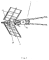
- FIG. 1 shows an antenna 1, in particular an antenna for telecommunications, in particular for the reception of radio and / or television signals, the at least one rod 2 with director elements (121 in FIG. 1 ), a dipole 13, a connecting element 24 and a housing 14 which encloses at least a part of at least one rod 2.
- the housing 14 at least a first fastening element 15 and a second fastening element 17, wherein the first fastening element 15, the rod 12 (2 in FIG. 1 ) in a first position 16, and wherein the second fastener 17 secures the rod 12 in a second position 18.
- the housing 14 is disposed directly on the dipole 13, it is in particular adjacent to the dipole 13, it is in particular mechanically connected to the dipole 13.
- the housing 14 includes a plurality of first fasteners 15 securing a plurality of rods 12 in a plurality of first positions 16 and a plurality of second fasteners 17 securing a plurality of rods 12 in a plurality of second positions 18.
- the first fastening element 15 has at least a first retaining element 19 and a second retaining element 110, wherein the first retaining element 19 and the second Holding member 110 have a distance from each other, which corresponds to the width of the rod 12.
- the holding elements 19, 110 of the first fastening element 15 consist of a triangular dividing wall 111 and of a rectangular dividing wall 112.
- the first fastening element 15 has three openings 113, wherein in each opening 113, a director element 121 of the rod 12 is arranged.
- the second fastening element 17 has at least a third retaining element 114 and a fourth retaining element 115, wherein the third retaining element 114 and the fourth retaining element 115 have a distance from each other which corresponds to the width of the rod 12.
- the holding elements 114, 115 of the second fastening element 17 consist of a triangular partition wall 116 and of a rectangular longitudinal partition wall 117, which bears against a part of the rod 12 and fixes it.
- the second fastening element 17 has three openings 113, wherein in particular in each opening 113 a director element 121 of the rod 12 is arranged.
- two of the three openings 113, 118 in which the director elements 21 of the rod 12 (in FIG. 2 are arranged in the shape of an ellipse, wherein the smaller axis corresponds to the external diameter of the director elements 21 of the rod 12.
- the first holding member 19 and the third holding member 114 are disposed on a projecting platform 119.
- the triangular partitions 111, 116 form a ramp 120 for the movement of the rod 12 from the first position 16 to the second position 18 and vice versa.
- the housing is composed of a first cover 141 and a second cover 142, wherein the first cover 141 and the second cover 142 have first fixing members 15 having the same shape and second fixing members 17 having the same shape.
- the first cover 141 and the second cover 142, which form the housing, have two tongues 122, which are arranged on the dipole 13.
- FIGS. 4 and 5 show a mechanical fastener, 24, which is also in FIG. 1 is shown, the two mechanical elements of the antenna, a first element 22, for example, the rod 2 in FIG. 1 , and a second element 23 "eg the dipole 13 in FIG. 1 , mechanically interconnects and forms an angle between the first element 22 and the second element 23.
- the connecting element 24 has at least one first opening 25 and at least one second opening 27; at the in the FIGS. 4 and 5
- the prevention element 24 has two first openings 25 and two second openings 27.
- the first openings 25 hold the second element 23 (eg dipole 13 in FIG FIG. 1 ) in an off-axis position 26, while the second openings 27 hook the second element 23 in an end position,
- a guide member 29 connects a first opening 25 to a second opening 27, as exemplified in FIGS FIGS. 4 and 5 shown
- the guide member 29 in the region of the first opening 25 on a flat ramp 210 and a curved ramp 211.
- the first opening 25 has a circular area (circular zone 212) in which a circular area (circular element 213) of the second element 23 is arranged in an initial position 26 or in an end position 28,
- the guide element 29 in the region of the second opening at least one section 214, which corresponds to the shape of the second element 23.
- the guide element 29 has two sections 214, which correspond to the shape of the second element 23 of the antenna.
- the connecting element 24 has a galvanic connection between the part where the first element 22 of the antenna is arranged and the part where the second element 23 is arranged in its end position 28.
- the connecting element 24 consists for example of a metallic material or of plastic.
Landscapes
- Support Of Aerials (AREA)
- Variable-Direction Aerials And Aerial Arrays (AREA)
- Details Of Aerials (AREA)
Priority Applications (1)
| Application Number | Priority Date | Filing Date | Title |
|---|---|---|---|
| PL11000287T PL2346115T3 (pl) | 2010-01-15 | 2011-01-14 | Antena |
Applications Claiming Priority (4)
| Application Number | Priority Date | Filing Date | Title |
|---|---|---|---|
| ES201000065A ES2386443B2 (es) | 2010-01-15 | 2010-01-15 | Antena de telecomunicacion |
| ES201000049U ES1072895Y (es) | 2010-01-15 | 2010-01-15 | Antena de telecomunicacion |
| ES201000064A ES2385006B2 (es) | 2010-01-15 | 2010-01-15 | Antena de telecomunicación. |
| ES201000050U ES1071874Y (es) | 2010-01-15 | 2010-01-15 | Antena de telecomunicacion |
Publications (3)
| Publication Number | Publication Date |
|---|---|
| EP2346115A2 EP2346115A2 (de) | 2011-07-20 |
| EP2346115A3 EP2346115A3 (de) | 2011-08-17 |
| EP2346115B1 true EP2346115B1 (de) | 2012-10-31 |
Family
ID=43734319
Family Applications (1)
| Application Number | Title | Priority Date | Filing Date |
|---|---|---|---|
| EP11000287A Active EP2346115B1 (de) | 2010-01-15 | 2011-01-14 | Antenne |
Country Status (4)
| Country | Link |
|---|---|
| EP (1) | EP2346115B1 (pl) |
| ES (1) | ES2422957T3 (pl) |
| PL (1) | PL2346115T3 (pl) |
| PT (1) | PT2346115E (pl) |
Families Citing this family (8)
| Publication number | Priority date | Publication date | Assignee | Title |
|---|---|---|---|---|
| EP2621014A1 (en) * | 2012-01-24 | 2013-07-31 | Angel Iglesias, S.A. | System and method for reducing interferences in television signals receiving systems |
| ES2467015B2 (es) * | 2012-04-27 | 2014-11-04 | Televes, S.A. | Antena |
| ES2467016B2 (es) * | 2012-04-27 | 2014-11-04 | Televes, S.A. | Antena |
| ES1077822Y (es) * | 2012-09-11 | 2013-01-18 | Fagor S Coop (100 0%) | Antena para la recepción de TV digital terrestre |
| ES2539524B1 (es) * | 2013-12-30 | 2016-04-13 | Televes, S.A. | Antena |
| ES2533226B2 (es) * | 2013-10-03 | 2015-09-29 | Televes, S.A. | Antena y procedimiento para la recepción de señales de telecomunicación |
| ES2540380B1 (es) * | 2013-12-30 | 2016-04-20 | Televes, S.A. | Antena |
| ES2634787T3 (es) * | 2013-10-03 | 2017-09-29 | Televés, S.A. | Antena y procedimiento para la recepción de señales de telecomunicación |
Family Cites Families (6)
| Publication number | Priority date | Publication date | Assignee | Title |
|---|---|---|---|---|
| GB1036158A (en) * | 1963-05-20 | 1966-07-13 | North Western Specialities Ltd | Improvements in aerials |
| DE1591485A1 (de) * | 1967-04-27 | 1969-11-27 | Siemens Ag | Vorrichtung zur Verbindung eines Antennenlaengstraegers mit einem quer dazu verlaufenden klappbaren Reflektortraeger |
| JPS5320217Y2 (pl) * | 1973-07-30 | 1978-05-27 | ||
| DE7836851U1 (de) * | 1978-12-13 | 1979-05-10 | Richard Hirschmann Radiotechnisches Werk, 7300 Esslingen | Schwenkbarer traeger eines mit abstand von einem laengstraeger angeordneten antennenelementes |
| JPS6162417U (pl) * | 1984-09-28 | 1986-04-26 | ||
| EP2093836A1 (de) * | 2008-02-19 | 2009-08-26 | Televes, S.A. | Yagiantenne |
-
2011
- 2011-01-14 PL PL11000287T patent/PL2346115T3/pl unknown
- 2011-01-14 EP EP11000287A patent/EP2346115B1/de active Active
- 2011-01-14 PT PT110002870T patent/PT2346115E/pt unknown
- 2011-01-14 ES ES11000287T patent/ES2422957T3/es active Active
Also Published As
| Publication number | Publication date |
|---|---|
| PT2346115E (pt) | 2013-02-04 |
| EP2346115A3 (de) | 2011-08-17 |
| PL2346115T3 (pl) | 2013-03-29 |
| EP2346115A2 (de) | 2011-07-20 |
| ES2422957T3 (es) | 2013-09-16 |
Similar Documents
| Publication | Publication Date | Title |
|---|---|---|
| EP3220480B1 (de) | Dipolförmige strahleranordnung | |
| EP3097604B1 (de) | Antenne, insbesondere mobilfunkantenne | |
| EP2346115A2 (de) | Antenne | |
| EP2929589B1 (de) | Dualpolarisierte, omnidirektionale antenne | |
| DE60103437T2 (de) | In Fahrzeugkabine montierte breitbandige Antenne | |
| DE19912465C2 (de) | Mehr-Bereichs-Antennenanlage | |
| DE60103573T2 (de) | In Fahrzeugkabine montierte breitbandige Antenne | |
| DE3840383A1 (de) | Mikrowellen-planar-antenne | |
| EP1470615A1 (de) | Dualpolarisierte strahleranordnung | |
| DE102014013926A1 (de) | Mehrstruktur-Breitband-Monopolantenne für zwei durch eine Frequenzlücke getrennte Frequenzbänder im Dezimeterwellenbereich für Fahrzeuge | |
| DE102017217117B3 (de) | GNSS-Antenne | |
| DE102012217113A1 (de) | Antennenstruktur einer zirkularpolarisierten Antenne für ein Fahrzeug | |
| DE102019119081A1 (de) | Verbundantennenvorrichtung mit gemeinsam genutztem element | |
| DE2358613A1 (de) | Faltdipol und empfangsantenne mit einem derartigen faltdipol | |
| DE2410498A1 (de) | Logarithmisch-periodische antenne | |
| EP2093837B1 (de) | Antenne | |
| DE3439414A1 (de) | Antennenerreger fuer mindestens zwei unterschiedliche frequenzbaender | |
| DE102018201575B3 (de) | Antennenvorrichtung | |
| DE19522436C2 (de) | Antennengehäuse | |
| DE102012215083B4 (de) | Antenne, Verfahren zum Herstellen einer Wellenleiter Antenne sowie ein Hochfrequenz-Front-End | |
| DE4219168A1 (de) | Rundstrahlantenne | |
| DE3439416C2 (pl) | ||
| DE2139257C3 (de) | Rundstrahl-Sendeantenne mit von einer Mittenträgeranordnung ausgehenden Strahlerelementen | |
| DE2029048C3 (de) | Antennenanordnung für ein Luft- oder Raumfahrzeug | |
| DE2156053A1 (de) | Richtstrahlfeld mit zirkularer oder elliptischer polarisation |
Legal Events
| Date | Code | Title | Description |
|---|---|---|---|
| PUAI | Public reference made under article 153(3) epc to a published international application that has entered the european phase |
Free format text: ORIGINAL CODE: 0009012 |
|
| PUAL | Search report despatched |
Free format text: ORIGINAL CODE: 0009013 |
|
| AK | Designated contracting states |
Kind code of ref document: A2 Designated state(s): AL AT BE BG CH CY CZ DE DK EE ES FI FR GB GR HR HU IE IS IT LI LT LU LV MC MK MT NL NO PL PT RO RS SE SI SK SM TR |
|
| AX | Request for extension of the european patent |
Extension state: BA ME |
|
| AK | Designated contracting states |
Kind code of ref document: A3 Designated state(s): AL AT BE BG CH CY CZ DE DK EE ES FI FR GB GR HR HU IE IS IT LI LT LU LV MC MK MT NL NO PL PT RO RS SE SI SK SM TR |
|
| AX | Request for extension of the european patent |
Extension state: BA ME |
|
| RIC1 | Information provided on ipc code assigned before grant |
Ipc: H01Q 19/30 20060101AFI20110711BHEP Ipc: H01Q 19/04 20060101ALI20110711BHEP |
|
| 17P | Request for examination filed |
Effective date: 20120217 |
|
| GRAP | Despatch of communication of intention to grant a patent |
Free format text: ORIGINAL CODE: EPIDOSNIGR1 |
|
| GRAP | Despatch of communication of intention to grant a patent |
Free format text: ORIGINAL CODE: EPIDOSNIGR1 |
|
| GRAS | Grant fee paid |
Free format text: ORIGINAL CODE: EPIDOSNIGR3 |
|
| GRAA | (expected) grant |
Free format text: ORIGINAL CODE: 0009210 |
|
| AK | Designated contracting states |
Kind code of ref document: B1 Designated state(s): AL AT BE BG CH CY CZ DE DK EE ES FI FR GB GR HR HU IE IS IT LI LT LU LV MC MK MT NL NO PL PT RO RS SE SI SK SM TR |
|
| REG | Reference to a national code |
Ref country code: GB Ref legal event code: FG4D Free format text: NOT ENGLISH Ref country code: CH Ref legal event code: EP |
|
| REG | Reference to a national code |
Ref country code: AT Ref legal event code: REF Ref document number: 582438 Country of ref document: AT Kind code of ref document: T Effective date: 20121115 |
|
| REG | Reference to a national code |
Ref country code: IE Ref legal event code: FG4D Free format text: LANGUAGE OF EP DOCUMENT: GERMAN |
|
| REG | Reference to a national code |
Ref country code: DE Ref legal event code: R096 Ref document number: 502011000167 Country of ref document: DE Effective date: 20121227 |
|
| REG | Reference to a national code |
Ref country code: PT Ref legal event code: SC4A Free format text: AVAILABILITY OF NATIONAL TRANSLATION Effective date: 20130129 |
|
| REG | Reference to a national code |
Ref country code: LT Ref legal event code: MG4D |
|
| REG | Reference to a national code |
Ref country code: PL Ref legal event code: T3 |
|
| REG | Reference to a national code |
Ref country code: NL Ref legal event code: VDEP Effective date: 20121031 |
|
| PG25 | Lapsed in a contracting state [announced via postgrant information from national office to epo] |
Ref country code: SE Free format text: LAPSE BECAUSE OF FAILURE TO SUBMIT A TRANSLATION OF THE DESCRIPTION OR TO PAY THE FEE WITHIN THE PRESCRIBED TIME-LIMIT Effective date: 20121031 Ref country code: HR Free format text: LAPSE BECAUSE OF FAILURE TO SUBMIT A TRANSLATION OF THE DESCRIPTION OR TO PAY THE FEE WITHIN THE PRESCRIBED TIME-LIMIT Effective date: 20121031 Ref country code: IS Free format text: LAPSE BECAUSE OF FAILURE TO SUBMIT A TRANSLATION OF THE DESCRIPTION OR TO PAY THE FEE WITHIN THE PRESCRIBED TIME-LIMIT Effective date: 20130228 Ref country code: FI Free format text: LAPSE BECAUSE OF FAILURE TO SUBMIT A TRANSLATION OF THE DESCRIPTION OR TO PAY THE FEE WITHIN THE PRESCRIBED TIME-LIMIT Effective date: 20121031 Ref country code: NO Free format text: LAPSE BECAUSE OF FAILURE TO SUBMIT A TRANSLATION OF THE DESCRIPTION OR TO PAY THE FEE WITHIN THE PRESCRIBED TIME-LIMIT Effective date: 20130131 Ref country code: NL Free format text: LAPSE BECAUSE OF FAILURE TO SUBMIT A TRANSLATION OF THE DESCRIPTION OR TO PAY THE FEE WITHIN THE PRESCRIBED TIME-LIMIT Effective date: 20121031 Ref country code: LT Free format text: LAPSE BECAUSE OF FAILURE TO SUBMIT A TRANSLATION OF THE DESCRIPTION OR TO PAY THE FEE WITHIN THE PRESCRIBED TIME-LIMIT Effective date: 20121031 |
|
| PG25 | Lapsed in a contracting state [announced via postgrant information from national office to epo] |
Ref country code: LV Free format text: LAPSE BECAUSE OF FAILURE TO SUBMIT A TRANSLATION OF THE DESCRIPTION OR TO PAY THE FEE WITHIN THE PRESCRIBED TIME-LIMIT Effective date: 20121031 Ref country code: SI Free format text: LAPSE BECAUSE OF FAILURE TO SUBMIT A TRANSLATION OF THE DESCRIPTION OR TO PAY THE FEE WITHIN THE PRESCRIBED TIME-LIMIT Effective date: 20121031 Ref country code: GR Free format text: LAPSE BECAUSE OF FAILURE TO SUBMIT A TRANSLATION OF THE DESCRIPTION OR TO PAY THE FEE WITHIN THE PRESCRIBED TIME-LIMIT Effective date: 20130201 |
|
| BERE | Be: lapsed |
Owner name: TELEVES, S.A. Effective date: 20130131 |
|
| PG25 | Lapsed in a contracting state [announced via postgrant information from national office to epo] |
Ref country code: EE Free format text: LAPSE BECAUSE OF FAILURE TO SUBMIT A TRANSLATION OF THE DESCRIPTION OR TO PAY THE FEE WITHIN THE PRESCRIBED TIME-LIMIT Effective date: 20121031 Ref country code: BG Free format text: LAPSE BECAUSE OF FAILURE TO SUBMIT A TRANSLATION OF THE DESCRIPTION OR TO PAY THE FEE WITHIN THE PRESCRIBED TIME-LIMIT Effective date: 20130131 Ref country code: DK Free format text: LAPSE BECAUSE OF FAILURE TO SUBMIT A TRANSLATION OF THE DESCRIPTION OR TO PAY THE FEE WITHIN THE PRESCRIBED TIME-LIMIT Effective date: 20121031 Ref country code: RS Free format text: LAPSE BECAUSE OF FAILURE TO SUBMIT A TRANSLATION OF THE DESCRIPTION OR TO PAY THE FEE WITHIN THE PRESCRIBED TIME-LIMIT Effective date: 20121031 Ref country code: SK Free format text: LAPSE BECAUSE OF FAILURE TO SUBMIT A TRANSLATION OF THE DESCRIPTION OR TO PAY THE FEE WITHIN THE PRESCRIBED TIME-LIMIT Effective date: 20121031 Ref country code: CZ Free format text: LAPSE BECAUSE OF FAILURE TO SUBMIT A TRANSLATION OF THE DESCRIPTION OR TO PAY THE FEE WITHIN THE PRESCRIBED TIME-LIMIT Effective date: 20121031 |
|
| PG25 | Lapsed in a contracting state [announced via postgrant information from national office to epo] |
Ref country code: MC Free format text: LAPSE BECAUSE OF NON-PAYMENT OF DUE FEES Effective date: 20130131 Ref country code: RO Free format text: LAPSE BECAUSE OF FAILURE TO SUBMIT A TRANSLATION OF THE DESCRIPTION OR TO PAY THE FEE WITHIN THE PRESCRIBED TIME-LIMIT Effective date: 20121031 |
|
| PLBE | No opposition filed within time limit |
Free format text: ORIGINAL CODE: 0009261 |
|
| STAA | Information on the status of an ep patent application or granted ep patent |
Free format text: STATUS: NO OPPOSITION FILED WITHIN TIME LIMIT |
|
| REG | Reference to a national code |
Ref country code: ES Ref legal event code: FG2A Ref document number: 2422957 Country of ref document: ES Kind code of ref document: T3 Effective date: 20130916 |
|
| 26N | No opposition filed |
Effective date: 20130801 |
|
| REG | Reference to a national code |
Ref country code: IE Ref legal event code: MM4A |
|
| PG25 | Lapsed in a contracting state [announced via postgrant information from national office to epo] |
Ref country code: BE Free format text: LAPSE BECAUSE OF NON-PAYMENT OF DUE FEES Effective date: 20130131 |
|
| REG | Reference to a national code |
Ref country code: DE Ref legal event code: R097 Ref document number: 502011000167 Country of ref document: DE Effective date: 20130801 |
|
| PG25 | Lapsed in a contracting state [announced via postgrant information from national office to epo] |
Ref country code: CY Free format text: LAPSE BECAUSE OF FAILURE TO SUBMIT A TRANSLATION OF THE DESCRIPTION OR TO PAY THE FEE WITHIN THE PRESCRIBED TIME-LIMIT Effective date: 20121031 |
|
| PG25 | Lapsed in a contracting state [announced via postgrant information from national office to epo] |
Ref country code: AL Free format text: LAPSE BECAUSE OF FAILURE TO SUBMIT A TRANSLATION OF THE DESCRIPTION OR TO PAY THE FEE WITHIN THE PRESCRIBED TIME-LIMIT Effective date: 20121031 Ref country code: IE Free format text: LAPSE BECAUSE OF NON-PAYMENT OF DUE FEES Effective date: 20130114 |
|
| PG25 | Lapsed in a contracting state [announced via postgrant information from national office to epo] |
Ref country code: MT Free format text: LAPSE BECAUSE OF FAILURE TO SUBMIT A TRANSLATION OF THE DESCRIPTION OR TO PAY THE FEE WITHIN THE PRESCRIBED TIME-LIMIT Effective date: 20121031 |
|
| REG | Reference to a national code |
Ref country code: CH Ref legal event code: PL |
|
| PG25 | Lapsed in a contracting state [announced via postgrant information from national office to epo] |
Ref country code: CH Free format text: LAPSE BECAUSE OF NON-PAYMENT OF DUE FEES Effective date: 20140131 Ref country code: LI Free format text: LAPSE BECAUSE OF NON-PAYMENT OF DUE FEES Effective date: 20140131 |
|
| PG25 | Lapsed in a contracting state [announced via postgrant information from national office to epo] |
Ref country code: SM Free format text: LAPSE BECAUSE OF FAILURE TO SUBMIT A TRANSLATION OF THE DESCRIPTION OR TO PAY THE FEE WITHIN THE PRESCRIBED TIME-LIMIT Effective date: 20121031 |
|
| PG25 | Lapsed in a contracting state [announced via postgrant information from national office to epo] |
Ref country code: TR Free format text: LAPSE BECAUSE OF FAILURE TO SUBMIT A TRANSLATION OF THE DESCRIPTION OR TO PAY THE FEE WITHIN THE PRESCRIBED TIME-LIMIT Effective date: 20121031 |
|
| PG25 | Lapsed in a contracting state [announced via postgrant information from national office to epo] |
Ref country code: HU Free format text: LAPSE BECAUSE OF FAILURE TO SUBMIT A TRANSLATION OF THE DESCRIPTION OR TO PAY THE FEE WITHIN THE PRESCRIBED TIME-LIMIT; INVALID AB INITIO Effective date: 20110114 Ref country code: MK Free format text: LAPSE BECAUSE OF FAILURE TO SUBMIT A TRANSLATION OF THE DESCRIPTION OR TO PAY THE FEE WITHIN THE PRESCRIBED TIME-LIMIT Effective date: 20121031 Ref country code: LU Free format text: LAPSE BECAUSE OF NON-PAYMENT OF DUE FEES Effective date: 20130114 |
|
| REG | Reference to a national code |
Ref country code: FR Ref legal event code: PLFP Year of fee payment: 6 |
|
| REG | Reference to a national code |
Ref country code: FR Ref legal event code: PLFP Year of fee payment: 7 |
|
| REG | Reference to a national code |
Ref country code: AT Ref legal event code: MM01 Ref document number: 582438 Country of ref document: AT Kind code of ref document: T Effective date: 20160114 |
|
| PG25 | Lapsed in a contracting state [announced via postgrant information from national office to epo] |
Ref country code: AT Free format text: LAPSE BECAUSE OF NON-PAYMENT OF DUE FEES Effective date: 20160114 |
|
| REG | Reference to a national code |
Ref country code: FR Ref legal event code: PLFP Year of fee payment: 8 |
|
| REG | Reference to a national code |
Ref country code: DE Ref legal event code: R082 Ref document number: 502011000167 Country of ref document: DE |
|
| PGFP | Annual fee paid to national office [announced via postgrant information from national office to epo] |
Ref country code: PL Payment date: 20241220 Year of fee payment: 15 |
|
| PGFP | Annual fee paid to national office [announced via postgrant information from national office to epo] |
Ref country code: GB Payment date: 20260113 Year of fee payment: 16 |
|
| PGFP | Annual fee paid to national office [announced via postgrant information from national office to epo] |
Ref country code: ES Payment date: 20260202 Year of fee payment: 16 |
|
| PGFP | Annual fee paid to national office [announced via postgrant information from national office to epo] |
Ref country code: DE Payment date: 20260114 Year of fee payment: 16 |
|
| PGFP | Annual fee paid to national office [announced via postgrant information from national office to epo] |
Ref country code: IT Payment date: 20260114 Year of fee payment: 16 |
|
| PGFP | Annual fee paid to national office [announced via postgrant information from national office to epo] |
Ref country code: FR Payment date: 20260113 Year of fee payment: 16 |
|
| PGFP | Annual fee paid to national office [announced via postgrant information from national office to epo] |
Ref country code: PT Payment date: 20260116 Year of fee payment: 16 |