EP2345937B1 - Charging roller, process cartridge and electrophotographic device - Google Patents
Charging roller, process cartridge and electrophotographic device Download PDFInfo
- Publication number
- EP2345937B1 EP2345937B1 EP09823723.3A EP09823723A EP2345937B1 EP 2345937 B1 EP2345937 B1 EP 2345937B1 EP 09823723 A EP09823723 A EP 09823723A EP 2345937 B1 EP2345937 B1 EP 2345937B1
- Authority
- EP
- European Patent Office
- Prior art keywords
- particles
- graphitized
- particle
- convex portions
- derived
- Prior art date
- Legal status (The legal status is an assumption and is not a legal conclusion. Google has not performed a legal analysis and makes no representation as to the accuracy of the status listed.)
- Active
Links
- 238000000034 method Methods 0.000 title claims description 45
- 230000008569 process Effects 0.000 title claims description 14
- 239000002245 particle Substances 0.000 claims description 423
- 229920005989 resin Polymers 0.000 claims description 172
- 239000011347 resin Substances 0.000 claims description 172
- 239000002344 surface layer Substances 0.000 claims description 73
- 239000006229 carbon black Substances 0.000 claims description 35
- 239000011230 binding agent Substances 0.000 claims description 20
- 238000000576 coating method Methods 0.000 description 66
- 239000000463 material Substances 0.000 description 57
- 239000011248 coating agent Substances 0.000 description 56
- 238000004519 manufacturing process Methods 0.000 description 39
- 239000010410 layer Substances 0.000 description 35
- 235000019241 carbon black Nutrition 0.000 description 34
- YXFVVABEGXRONW-UHFFFAOYSA-N Toluene Chemical compound CC1=CC=CC=C1 YXFVVABEGXRONW-UHFFFAOYSA-N 0.000 description 18
- 239000000047 product Substances 0.000 description 17
- 239000006185 dispersion Substances 0.000 description 16
- 239000011302 mesophase pitch Substances 0.000 description 15
- 238000002360 preparation method Methods 0.000 description 15
- 238000005259 measurement Methods 0.000 description 14
- 238000010438 heat treatment Methods 0.000 description 13
- 238000011156 evaluation Methods 0.000 description 12
- 238000001354 calcination Methods 0.000 description 11
- 239000006258 conductive agent Substances 0.000 description 11
- 238000010586 diagram Methods 0.000 description 11
- 239000010419 fine particle Substances 0.000 description 11
- 239000011521 glass Substances 0.000 description 11
- 239000002931 mesocarbon microbead Substances 0.000 description 10
- OKTJSMMVPCPJKN-UHFFFAOYSA-N Carbon Chemical compound [C] OKTJSMMVPCPJKN-UHFFFAOYSA-N 0.000 description 9
- 239000011324 bead Substances 0.000 description 9
- 239000000571 coke Substances 0.000 description 9
- 238000009826 distribution Methods 0.000 description 9
- 230000005684 electric field Effects 0.000 description 9
- 239000000203 mixture Substances 0.000 description 9
- GWEVSGVZZGPLCZ-UHFFFAOYSA-N Titan oxide Chemical compound O=[Ti]=O GWEVSGVZZGPLCZ-UHFFFAOYSA-N 0.000 description 8
- 230000001070 adhesive effect Effects 0.000 description 8
- 239000002131 composite material Substances 0.000 description 8
- 238000004132 cross linking Methods 0.000 description 8
- 229920001971 elastomer Polymers 0.000 description 8
- 239000002243 precursor Substances 0.000 description 8
- 239000005060 rubber Substances 0.000 description 8
- 239000000853 adhesive Substances 0.000 description 7
- 238000005087 graphitization Methods 0.000 description 7
- 239000011295 pitch Substances 0.000 description 7
- OGIDPMRJRNCKJF-UHFFFAOYSA-N titanium oxide Inorganic materials [Ti]=O OGIDPMRJRNCKJF-UHFFFAOYSA-N 0.000 description 7
- UHOVQNZJYSORNB-UHFFFAOYSA-N Benzene Chemical compound C1=CC=CC=C1 UHOVQNZJYSORNB-UHFFFAOYSA-N 0.000 description 6
- 239000012298 atmosphere Substances 0.000 description 6
- 238000000227 grinding Methods 0.000 description 6
- 239000005011 phenolic resin Substances 0.000 description 6
- 238000012546 transfer Methods 0.000 description 6
- IJGRMHOSHXDMSA-UHFFFAOYSA-N Atomic nitrogen Chemical compound N#N IJGRMHOSHXDMSA-UHFFFAOYSA-N 0.000 description 5
- NTIZESTWPVYFNL-UHFFFAOYSA-N Methyl isobutyl ketone Chemical compound CC(C)CC(C)=O NTIZESTWPVYFNL-UHFFFAOYSA-N 0.000 description 5
- UIHCLUNTQKBZGK-UHFFFAOYSA-N Methyl isobutyl ketone Natural products CCC(C)C(C)=O UIHCLUNTQKBZGK-UHFFFAOYSA-N 0.000 description 5
- 150000001875 compounds Chemical class 0.000 description 5
- 229910002804 graphite Inorganic materials 0.000 description 5
- 239000010439 graphite Substances 0.000 description 5
- 229940043265 methyl isobutyl ketone Drugs 0.000 description 5
- 239000002994 raw material Substances 0.000 description 5
- 238000003756 stirring Methods 0.000 description 5
- 239000000725 suspension Substances 0.000 description 5
- 229920001897 terpolymer Polymers 0.000 description 5
- 229920000178 Acrylic resin Polymers 0.000 description 4
- 239000005057 Hexamethylene diisocyanate Substances 0.000 description 4
- XEEYBQQBJWHFJM-UHFFFAOYSA-N Iron Chemical compound [Fe] XEEYBQQBJWHFJM-UHFFFAOYSA-N 0.000 description 4
- 101000941926 Saccharomyces cerevisiae (strain ATCC 204508 / S288c) Carboxypeptidase Y inhibitor Proteins 0.000 description 4
- VYPSYNLAJGMNEJ-UHFFFAOYSA-N Silicium dioxide Chemical compound O=[Si]=O VYPSYNLAJGMNEJ-UHFFFAOYSA-N 0.000 description 4
- QVGXLLKOCUKJST-UHFFFAOYSA-N atomic oxygen Chemical compound [O] QVGXLLKOCUKJST-UHFFFAOYSA-N 0.000 description 4
- 239000007795 chemical reaction product Substances 0.000 description 4
- 239000003795 chemical substances by application Substances 0.000 description 4
- 230000000052 comparative effect Effects 0.000 description 4
- 229920001577 copolymer Polymers 0.000 description 4
- 238000003618 dip coating Methods 0.000 description 4
- 230000000694 effects Effects 0.000 description 4
- 229920005558 epichlorohydrin rubber Polymers 0.000 description 4
- -1 fluororesins Polymers 0.000 description 4
- RRAMGCGOFNQTLD-UHFFFAOYSA-N hexamethylene diisocyanate Chemical compound O=C=NCCCCCCN=C=O RRAMGCGOFNQTLD-UHFFFAOYSA-N 0.000 description 4
- 238000000465 moulding Methods 0.000 description 4
- 230000003647 oxidation Effects 0.000 description 4
- 238000007254 oxidation reaction Methods 0.000 description 4
- 239000001301 oxygen Substances 0.000 description 4
- 229910052760 oxygen Inorganic materials 0.000 description 4
- 239000005056 polyisocyanate Substances 0.000 description 4
- 229920001228 polyisocyanate Polymers 0.000 description 4
- 238000006116 polymerization reaction Methods 0.000 description 4
- 239000002002 slurry Substances 0.000 description 4
- 239000007787 solid Substances 0.000 description 4
- 239000002904 solvent Substances 0.000 description 4
- 238000001228 spectrum Methods 0.000 description 4
- 239000003381 stabilizer Substances 0.000 description 4
- 239000000126 substance Substances 0.000 description 4
- 230000003746 surface roughness Effects 0.000 description 4
- 229920001187 thermosetting polymer Polymers 0.000 description 4
- 239000004925 Acrylic resin Substances 0.000 description 3
- BRLQWZUYTZBJKN-UHFFFAOYSA-N Epichlorohydrin Chemical compound ClCC1CO1 BRLQWZUYTZBJKN-UHFFFAOYSA-N 0.000 description 3
- 230000015572 biosynthetic process Effects 0.000 description 3
- 238000004140 cleaning Methods 0.000 description 3
- 239000011294 coal tar pitch Substances 0.000 description 3
- 229910001873 dinitrogen Inorganic materials 0.000 description 3
- 238000010894 electron beam technology Methods 0.000 description 3
- 239000012948 isocyanate Substances 0.000 description 3
- 150000002513 isocyanates Chemical class 0.000 description 3
- 239000007788 liquid Substances 0.000 description 3
- 239000000178 monomer Substances 0.000 description 3
- 239000007790 solid phase Substances 0.000 description 3
- 229920002725 thermoplastic elastomer Polymers 0.000 description 3
- 229920002803 thermoplastic polyurethane Polymers 0.000 description 3
- XLYOFNOQVPJJNP-UHFFFAOYSA-N water Substances O XLYOFNOQVPJJNP-UHFFFAOYSA-N 0.000 description 3
- YHMYGUUIMTVXNW-UHFFFAOYSA-N 1,3-dihydrobenzimidazole-2-thione Chemical compound C1=CC=C2NC(S)=NC2=C1 YHMYGUUIMTVXNW-UHFFFAOYSA-N 0.000 description 2
- VZSRBBMJRBPUNF-UHFFFAOYSA-N 2-(2,3-dihydro-1H-inden-2-ylamino)-N-[3-oxo-3-(2,4,6,7-tetrahydrotriazolo[4,5-c]pyridin-5-yl)propyl]pyrimidine-5-carboxamide Chemical compound C1C(CC2=CC=CC=C12)NC1=NC=C(C=N1)C(=O)NCCC(N1CC2=C(CC1)NN=N2)=O VZSRBBMJRBPUNF-UHFFFAOYSA-N 0.000 description 2
- BUZICZZQJDLXJN-UHFFFAOYSA-N 3-azaniumyl-4-hydroxybutanoate Chemical compound OCC(N)CC(O)=O BUZICZZQJDLXJN-UHFFFAOYSA-N 0.000 description 2
- XKRFYHLGVUSROY-UHFFFAOYSA-N Argon Chemical compound [Ar] XKRFYHLGVUSROY-UHFFFAOYSA-N 0.000 description 2
- VTYYLEPIZMXCLO-UHFFFAOYSA-L Calcium carbonate Chemical compound [Ca+2].[O-]C([O-])=O VTYYLEPIZMXCLO-UHFFFAOYSA-L 0.000 description 2
- 229920000089 Cyclic olefin copolymer Polymers 0.000 description 2
- YCKRFDGAMUMZLT-UHFFFAOYSA-N Fluorine atom Chemical compound [F] YCKRFDGAMUMZLT-UHFFFAOYSA-N 0.000 description 2
- PXHVJJICTQNCMI-UHFFFAOYSA-N Nickel Chemical compound [Ni] PXHVJJICTQNCMI-UHFFFAOYSA-N 0.000 description 2
- 229920000459 Nitrile rubber Polymers 0.000 description 2
- 239000004721 Polyphenylene oxide Substances 0.000 description 2
- PPBRXRYQALVLMV-UHFFFAOYSA-N Styrene Chemical compound C=CC1=CC=CC=C1 PPBRXRYQALVLMV-UHFFFAOYSA-N 0.000 description 2
- UCKMPCXJQFINFW-UHFFFAOYSA-N Sulphide Chemical compound [S-2] UCKMPCXJQFINFW-UHFFFAOYSA-N 0.000 description 2
- XLOMVQKBTHCTTD-UHFFFAOYSA-N Zinc monoxide Chemical compound [Zn]=O XLOMVQKBTHCTTD-UHFFFAOYSA-N 0.000 description 2
- MCMNRKCIXSYSNV-UHFFFAOYSA-N Zirconium dioxide Chemical compound O=[Zr]=O MCMNRKCIXSYSNV-UHFFFAOYSA-N 0.000 description 2
- 239000000654 additive Substances 0.000 description 2
- 229910021383 artificial graphite Inorganic materials 0.000 description 2
- 238000006243 chemical reaction Methods 0.000 description 2
- 238000013329 compounding Methods 0.000 description 2
- 238000004821 distillation Methods 0.000 description 2
- 239000003822 epoxy resin Substances 0.000 description 2
- 238000001125 extrusion Methods 0.000 description 2
- 238000001914 filtration Methods 0.000 description 2
- 239000011737 fluorine Substances 0.000 description 2
- 229910052731 fluorine Inorganic materials 0.000 description 2
- 238000005194 fractionation Methods 0.000 description 2
- 239000000295 fuel oil Substances 0.000 description 2
- LNEPOXFFQSENCJ-UHFFFAOYSA-N haloperidol Chemical compound C1CC(O)(C=2C=CC(Cl)=CC=2)CCN1CCCC(=O)C1=CC=C(F)C=C1 LNEPOXFFQSENCJ-UHFFFAOYSA-N 0.000 description 2
- 150000002500 ions Chemical class 0.000 description 2
- 229910052742 iron Inorganic materials 0.000 description 2
- 239000007791 liquid phase Substances 0.000 description 2
- 239000003921 oil Substances 0.000 description 2
- 229920006122 polyamide resin Polymers 0.000 description 2
- 229920000647 polyepoxide Polymers 0.000 description 2
- 229920001225 polyester resin Polymers 0.000 description 2
- 239000004645 polyester resin Substances 0.000 description 2
- 229920000570 polyether Polymers 0.000 description 2
- 229920005862 polyol Polymers 0.000 description 2
- 239000011164 primary particle Substances 0.000 description 2
- 238000012545 processing Methods 0.000 description 2
- 238000010298 pulverizing process Methods 0.000 description 2
- 230000005855 radiation Effects 0.000 description 2
- 229920002050 silicone resin Polymers 0.000 description 2
- 238000005507 spraying Methods 0.000 description 2
- 229920000468 styrene butadiene styrene block copolymer Polymers 0.000 description 2
- 239000012756 surface treatment agent Substances 0.000 description 2
- 229920005992 thermoplastic resin Polymers 0.000 description 2
- DBCAQXHNJOFNGC-UHFFFAOYSA-N 4-bromo-1,1,1-trifluorobutane Chemical compound FC(F)(F)CCCBr DBCAQXHNJOFNGC-UHFFFAOYSA-N 0.000 description 1
- NIXOWILDQLNWCW-UHFFFAOYSA-M Acrylate Chemical compound [O-]C(=O)C=C NIXOWILDQLNWCW-UHFFFAOYSA-M 0.000 description 1
- 239000004342 Benzoyl peroxide Substances 0.000 description 1
- OMPJBNCRMGITSC-UHFFFAOYSA-N Benzoylperoxide Chemical compound C=1C=CC=CC=1C(=O)OOC(=O)C1=CC=CC=C1 OMPJBNCRMGITSC-UHFFFAOYSA-N 0.000 description 1
- RYGMFSIKBFXOCR-UHFFFAOYSA-N Copper Chemical compound [Cu] RYGMFSIKBFXOCR-UHFFFAOYSA-N 0.000 description 1
- 239000005977 Ethylene Substances 0.000 description 1
- 101000579613 Homo sapiens U6 snRNA-associated Sm-like protein LSm5 Proteins 0.000 description 1
- 239000005058 Isophorone diisocyanate Substances 0.000 description 1
- VVQNEPGJFQJSBK-UHFFFAOYSA-N Methyl methacrylate Chemical compound COC(=O)C(C)=C VVQNEPGJFQJSBK-UHFFFAOYSA-N 0.000 description 1
- 239000004677 Nylon Substances 0.000 description 1
- CTQNGGLPUBDAKN-UHFFFAOYSA-N O-Xylene Chemical compound CC1=CC=CC=C1C CTQNGGLPUBDAKN-UHFFFAOYSA-N 0.000 description 1
- 239000005062 Polybutadiene Substances 0.000 description 1
- 239000004372 Polyvinyl alcohol Substances 0.000 description 1
- 238000001069 Raman spectroscopy Methods 0.000 description 1
- 238000001237 Raman spectrum Methods 0.000 description 1
- 239000006087 Silane Coupling Agent Substances 0.000 description 1
- DBMJMQXJHONAFJ-UHFFFAOYSA-M Sodium laurylsulphate Chemical compound [Na+].CCCCCCCCCCCCOS([O-])(=O)=O DBMJMQXJHONAFJ-UHFFFAOYSA-M 0.000 description 1
- NINIDFKCEFEMDL-UHFFFAOYSA-N Sulfur Chemical compound [S] NINIDFKCEFEMDL-UHFFFAOYSA-N 0.000 description 1
- 102100028261 U6 snRNA-associated Sm-like protein LSm5 Human genes 0.000 description 1
- 229920006311 Urethane elastomer Polymers 0.000 description 1
- 230000001133 acceleration Effects 0.000 description 1
- 239000006230 acetylene black Substances 0.000 description 1
- 239000003522 acrylic cement Substances 0.000 description 1
- 239000004840 adhesive resin Substances 0.000 description 1
- 229920006223 adhesive resin Polymers 0.000 description 1
- 229920003232 aliphatic polyester Polymers 0.000 description 1
- 239000000956 alloy Substances 0.000 description 1
- 229910045601 alloy Inorganic materials 0.000 description 1
- 229910052782 aluminium Inorganic materials 0.000 description 1
- XAGFODPZIPBFFR-UHFFFAOYSA-N aluminium Chemical compound [Al] XAGFODPZIPBFFR-UHFFFAOYSA-N 0.000 description 1
- 239000003963 antioxidant agent Substances 0.000 description 1
- 230000003078 antioxidant effect Effects 0.000 description 1
- 239000008346 aqueous phase Substances 0.000 description 1
- 229910052786 argon Inorganic materials 0.000 description 1
- 235000019400 benzoyl peroxide Nutrition 0.000 description 1
- 230000005540 biological transmission Effects 0.000 description 1
- QHIWVLPBUQWDMQ-UHFFFAOYSA-N butyl prop-2-enoate;methyl 2-methylprop-2-enoate;prop-2-enoic acid Chemical compound OC(=O)C=C.COC(=O)C(C)=C.CCCCOC(=O)C=C QHIWVLPBUQWDMQ-UHFFFAOYSA-N 0.000 description 1
- 229910000019 calcium carbonate Inorganic materials 0.000 description 1
- 239000001506 calcium phosphate Substances 0.000 description 1
- 229910000389 calcium phosphate Inorganic materials 0.000 description 1
- 235000011010 calcium phosphates Nutrition 0.000 description 1
- 125000004432 carbon atom Chemical group C* 0.000 description 1
- 230000015556 catabolic process Effects 0.000 description 1
- 238000005119 centrifugation Methods 0.000 description 1
- 230000008859 change Effects 0.000 description 1
- 239000003245 coal Substances 0.000 description 1
- 238000000748 compression moulding Methods 0.000 description 1
- 238000007796 conventional method Methods 0.000 description 1
- 238000007334 copolymerization reaction Methods 0.000 description 1
- 229910052802 copper Inorganic materials 0.000 description 1
- 239000010949 copper Substances 0.000 description 1
- 230000007547 defect Effects 0.000 description 1
- 238000006731 degradation reaction Methods 0.000 description 1
- GYZLOYUZLJXAJU-UHFFFAOYSA-N diglycidyl ether Chemical compound C1OC1COCC1CO1 GYZLOYUZLJXAJU-UHFFFAOYSA-N 0.000 description 1
- 239000002612 dispersion medium Substances 0.000 description 1
- MYRTYDVEIRVNKP-UHFFFAOYSA-N divinylbenzene Substances C=CC1=CC=CC=C1C=C MYRTYDVEIRVNKP-UHFFFAOYSA-N 0.000 description 1
- 238000001035 drying Methods 0.000 description 1
- 239000000806 elastomer Substances 0.000 description 1
- 230000005611 electricity Effects 0.000 description 1
- 238000005516 engineering process Methods 0.000 description 1
- BXOUVIIITJXIKB-UHFFFAOYSA-N ethene;styrene Chemical group C=C.C=CC1=CC=CC=C1 BXOUVIIITJXIKB-UHFFFAOYSA-N 0.000 description 1
- STVZJERGLQHEKB-UHFFFAOYSA-N ethylene glycol dimethacrylate Substances CC(=C)C(=O)OCCOC(=O)C(C)=C STVZJERGLQHEKB-UHFFFAOYSA-N 0.000 description 1
- 230000005284 excitation Effects 0.000 description 1
- 239000000945 filler Substances 0.000 description 1
- 239000006232 furnace black Substances 0.000 description 1
- 230000005484 gravity Effects 0.000 description 1
- 238000009775 high-speed stirring Methods 0.000 description 1
- 125000002887 hydroxy group Chemical group [H]O* 0.000 description 1
- 230000006698 induction Effects 0.000 description 1
- 238000001746 injection moulding Methods 0.000 description 1
- 238000010884 ion-beam technique Methods 0.000 description 1
- 230000001678 irradiating effect Effects 0.000 description 1
- NIMLQBUJDJZYEJ-UHFFFAOYSA-N isophorone diisocyanate Chemical compound CC1(C)CC(N=C=O)CC(C)(CN=C=O)C1 NIMLQBUJDJZYEJ-UHFFFAOYSA-N 0.000 description 1
- 239000003273 ketjen black Substances 0.000 description 1
- 238000004898 kneading Methods 0.000 description 1
- 238000000691 measurement method Methods 0.000 description 1
- 230000007246 mechanism Effects 0.000 description 1
- 239000002609 medium Substances 0.000 description 1
- 238000002844 melting Methods 0.000 description 1
- 230000008018 melting Effects 0.000 description 1
- 229910052751 metal Inorganic materials 0.000 description 1
- 239000002184 metal Substances 0.000 description 1
- 150000002739 metals Chemical class 0.000 description 1
- 229910021382 natural graphite Inorganic materials 0.000 description 1
- 229910052759 nickel Inorganic materials 0.000 description 1
- 229910052757 nitrogen Inorganic materials 0.000 description 1
- 239000012299 nitrogen atmosphere Substances 0.000 description 1
- 229920001778 nylon Polymers 0.000 description 1
- 230000003287 optical effect Effects 0.000 description 1
- 230000001590 oxidative effect Effects 0.000 description 1
- 239000003973 paint Substances 0.000 description 1
- 239000003208 petroleum Substances 0.000 description 1
- 238000004525 petroleum distillation Methods 0.000 description 1
- 239000004014 plasticizer Substances 0.000 description 1
- 229920001084 poly(chloroprene) Polymers 0.000 description 1
- 229920002037 poly(vinyl butyral) polymer Polymers 0.000 description 1
- 229920002857 polybutadiene Polymers 0.000 description 1
- 238000006068 polycondensation reaction Methods 0.000 description 1
- 239000003505 polymerization initiator Substances 0.000 description 1
- 150000003077 polyols Chemical class 0.000 description 1
- 229920001296 polysiloxane Polymers 0.000 description 1
- 229920005990 polystyrene resin Polymers 0.000 description 1
- 229920002451 polyvinyl alcohol Polymers 0.000 description 1
- 238000003825 pressing Methods 0.000 description 1
- 150000003242 quaternary ammonium salts Chemical class 0.000 description 1
- 238000004439 roughness measurement Methods 0.000 description 1
- 238000007127 saponification reaction Methods 0.000 description 1
- 238000004062 sedimentation Methods 0.000 description 1
- 238000004904 shortening Methods 0.000 description 1
- 239000000377 silicon dioxide Substances 0.000 description 1
- 229920002379 silicone rubber Polymers 0.000 description 1
- 239000004945 silicone rubber Substances 0.000 description 1
- 235000019333 sodium laurylsulphate Nutrition 0.000 description 1
- 239000000243 solution Substances 0.000 description 1
- 239000012798 spherical particle Substances 0.000 description 1
- 230000000087 stabilizing effect Effects 0.000 description 1
- 239000010935 stainless steel Substances 0.000 description 1
- 229910001220 stainless steel Inorganic materials 0.000 description 1
- 230000003068 static effect Effects 0.000 description 1
- 229920006132 styrene block copolymer Polymers 0.000 description 1
- 229910052717 sulfur Inorganic materials 0.000 description 1
- 239000011593 sulfur Substances 0.000 description 1
- 238000010557 suspension polymerization reaction Methods 0.000 description 1
- 239000011269 tar Substances 0.000 description 1
- 239000006234 thermal black Substances 0.000 description 1
- QORWJWZARLRLPR-UHFFFAOYSA-H tricalcium bis(phosphate) Chemical compound [Ca+2].[Ca+2].[Ca+2].[O-]P([O-])([O-])=O.[O-]P([O-])([O-])=O QORWJWZARLRLPR-UHFFFAOYSA-H 0.000 description 1
- XYJRNCYWTVGEEG-UHFFFAOYSA-N trimethoxy(2-methylpropyl)silane Chemical compound CO[Si](OC)(OC)CC(C)C XYJRNCYWTVGEEG-UHFFFAOYSA-N 0.000 description 1
- 238000005406 washing Methods 0.000 description 1
- 239000008096 xylene Substances 0.000 description 1
- 239000011787 zinc oxide Substances 0.000 description 1
- XOOUIPVCVHRTMJ-UHFFFAOYSA-L zinc stearate Chemical compound [Zn+2].CCCCCCCCCCCCCCCCCC([O-])=O.CCCCCCCCCCCCCCCCCC([O-])=O XOOUIPVCVHRTMJ-UHFFFAOYSA-L 0.000 description 1
Images

Classifications
-
- G—PHYSICS
- G03—PHOTOGRAPHY; CINEMATOGRAPHY; ANALOGOUS TECHNIQUES USING WAVES OTHER THAN OPTICAL WAVES; ELECTROGRAPHY; HOLOGRAPHY
- G03G—ELECTROGRAPHY; ELECTROPHOTOGRAPHY; MAGNETOGRAPHY
- G03G15/00—Apparatus for electrographic processes using a charge pattern
- G03G15/02—Apparatus for electrographic processes using a charge pattern for laying down a uniform charge, e.g. for sensitising; Corona discharge devices
- G03G15/0208—Apparatus for electrographic processes using a charge pattern for laying down a uniform charge, e.g. for sensitising; Corona discharge devices by contact, friction or induction, e.g. liquid charging apparatus
- G03G15/0216—Apparatus for electrographic processes using a charge pattern for laying down a uniform charge, e.g. for sensitising; Corona discharge devices by contact, friction or induction, e.g. liquid charging apparatus by bringing a charging member into contact with the member to be charged, e.g. roller, brush chargers
- G03G15/0233—Structure, details of the charging member, e.g. chemical composition, surface properties
-
- G—PHYSICS
- G03—PHOTOGRAPHY; CINEMATOGRAPHY; ANALOGOUS TECHNIQUES USING WAVES OTHER THAN OPTICAL WAVES; ELECTROGRAPHY; HOLOGRAPHY
- G03G—ELECTROGRAPHY; ELECTROPHOTOGRAPHY; MAGNETOGRAPHY
- G03G21/00—Arrangements not provided for by groups G03G13/00 - G03G19/00, e.g. cleaning, elimination of residual charge
- G03G21/16—Mechanical means for facilitating the maintenance of the apparatus, e.g. modular arrangements
- G03G21/18—Mechanical means for facilitating the maintenance of the apparatus, e.g. modular arrangements using a processing cartridge, whereby the process cartridge comprises at least two image processing means in a single unit
-
- G—PHYSICS
- G03—PHOTOGRAPHY; CINEMATOGRAPHY; ANALOGOUS TECHNIQUES USING WAVES OTHER THAN OPTICAL WAVES; ELECTROGRAPHY; HOLOGRAPHY
- G03G—ELECTROGRAPHY; ELECTROPHOTOGRAPHY; MAGNETOGRAPHY
- G03G2215/00—Apparatus for electrophotographic processes
- G03G2215/02—Arrangements for laying down a uniform charge
- G03G2215/021—Arrangements for laying down a uniform charge by contact, friction or induction
- G03G2215/025—Arrangements for laying down a uniform charge by contact, friction or induction using contact charging means having lateral dimensions related to other apparatus means, e.g. photodrum, developing roller
Definitions
- the present invention relates to a charging roller which charges a subject to be charged by a contact charging method, a process cartridge, and an electrophotographic apparatus.
- Japanese Patent Application Laid-Open No. 2007-127777 discloses a charging roller having a surface layer containing resin particles which are formed of a resin in which a carbon black is dispersed (hereinafter, also, referred to as "CB-dispersed resin particles").
- US7054579 (B2 ) relates to a charging member having a support and one or more cover layer(s), the ten-point average surface roughness of the surface of the charging member, the height of a hill of the surface of the charging member, the area at the part of the hill, and the area of a region surrounded by hills each having the height H ( ⁇ m) and other hills each having a height of not less than the height H ( ⁇ m), and not including any hills having a height of more than 0.5H ( ⁇ m) satisfy a specific relationship.
- a surface layer of the charging member contains high-molecular compound particles whose average particle diameter is between 2 and 50 ⁇ m and whose range of particle size distribution of average particle diameter is above 0mum and not greater than 7 ⁇ m.
- EP1355199 (A2 ) relates to a conductive member having a support and provided thereon at least one cover layer, the cover layer having a surface layer, and the surface layer containing fine particles.
- fine particles present at the surface layer lower part corresponding to a range within 30% of the total layer thickness from the lowermost plane have an average particle diameter which is larger than the average particle diameter of fine particles present at the surface layer upper part corresponding to a range within 30% of the total layer thickness from the uppermost plane.
- the present inventors have studied, based on the conventional technique, a charging roller having a surface layer which contains CB-dispersed resin particles and has, on its surface, convex portions derived from the CB-dispersed resin particles.
- the present inventors have found that the CB-dispersed resin particles forming the convex portions easily induce electrostatic discharge because the CB-dispersed resin particles are made conductive by carbon black, and thus such a charging roller exhibits a stable chargeability even if toner and external additives adhere on its surface according to the use thereof.
- "fogging" can take place on an electrophotographic image formed through a charging step using such a charging roller.
- the present invention is directed to providing a charging roller having a stable chargeability and capable of preventing the occurrence of "fogging" on an electrophotographic image.
- the present invention is also directed to providing a process cartridge and an electrophotographic apparatus each capable of stably offering high-quality electrophotographic images.
- a charging roller according to the present invention is a contact charging type charging roller which includes a conductive support, and a surface layer, wherein the surface layer contains a binder, resin particles containing a carbon black dispersed in the binder, and graphitized particles dispersed in the binder; and the surface layer has, on its surface, convex portions derived from the resin particles, and convex portions derived from the graphitized particles, wherein the number of convex portions derived from the graphitized particles having a distance, as a positive value, from a plane surface including each vertex of three convex portions derived from the resin particles adjacent to one convex portion derived from the graphitized particles is 80% or more of the total number of the convex portions derived from the graphitized particles.
- An electrophotographic apparatus includes the charging roller and an electrophotographic photosensitive member which is arranged so as to be charged by the charging roller.
- a process cartridge includes the charging roller, and the electrophotographic photosensitive member, wherein the process cartridge is adapted to be detachably mounted to a main body of an electrophotographic apparatus.
- the charging roller of the present invention can prevent the occurrence of lateral streak images due to a charging defect of a photosensitive member, which is caused by extraneous matter attached onto a surface of the charging roller and can prevent degradation of image quality with increased image density.
- the charging roller of the present invention is capable of stabilizing the discharge property even under application of a large output current load and is suitably used for electrophotographic apparatuses, in which attempts are made to achieve further higher image quality, higher speed performance, and longer lives.
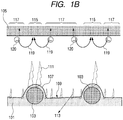
- the present inventors have presumed that the mechanism by which "fogging" occurs in an electrophotographic image by using a charging roller having, on its surface, convex portions derived from carbon black (CB) dispersed-resin particles as follows.
- CB carbon black
- FIG. 1B is a diagram schematically illustrating a discharge state in a nip portion between a charging roller having, on its surface, convex portions derived from CB-dispersed resin particles (hereinafter, also referred to as "CB-dispersed resin particle-derived convex portion(s)”), and an electrophotographic photosensitive member.
- CB-dispersed resin particle-derived convex portion(s) convex portions derived from CB-dispersed resin particles
- the area 115 is charged by discharge generated from the CB-dispersed resin particle-derived convex portions on the charging roller, and the area 117 is charged by discharge generated from the plane portion 109 of the surface of the charging roller. Since a great difference in the electrical potential occurs between the area 115 and the area 117, a local electric field 119 is induced between these areas. Under this condition, a toner 120 containing charged particles is trapped by the local electric field 119 to travel along a surface of the electrophotographic photosensitive member.
- the present inventors considered that due to this traveling of the toner, the toner adheres onto non-latent image portions of the surface of electrophotographic photosensitive member, causing "fogging" in an electrophotographic image.
- the present inventors thought that it would be possible to prevent "fogging" from adhering onto an electrophotographic photosensitive member by effecting electricity to be stably and appropriately discharged also from a plane portion between two CB-dispersed resin particle-derived convex portions while maintaining suitable discharge generated from the CB-dispersed resin particle-derived convex portions so as to weaken the intensity of the local electric fields generated at the surface of the electrophotographic photosensitive member.
- the present inventors produced a charging roller in which convex portions derived from graphitized particles (hereinafter, also referred to as “graphitized particle-derived convex portions") having a height lower than that of the CB-dispersed resin particle-derived convex portions are formed in the plane portion 109. Then, the present inventors studied and examined the chargeability of the thus produced charging roller and "fogging" in electrophotographic images formed using the charging roller. As a result, the present inventors have found that the charging roller has a stable chargeability, and the occurrence of "fogging" is substantially reduced in electrophotographic images formed using the charging roller. The present invention has been accomplished based on the findings.
- FIG. 1A is a diagram schematically illustrating a discharge phenomenon generated in a nip portion formed between a charging roller according to the present invention and an electrophotographic photosensitive member.
- a surface layer 201 of the charging roller contains CB-dispersed resin particles 103 and graphitized particles 203 having a higher conductivity than the CB-dispersed resin particles 103.
- the surface layer 201 has, its surface, the CB-dispersed resin particle-derived convex portions 107, and graphitized particle-derived convex portions 205.
- the graphitized particle-derived convex portions 205 are basically constructed so as not to come closer to the surface of the electrophotographic photosensitive member 105 than the CB-dispersed resin particle-derived convex portions 107 do.
- a discharge 207 is generated which is more intensive than a discharge 113 generating from the plane portion 109 in FIG. 1B toward the electrophotographic photosensitive member, which is not as intensive as a discharge intensity 111 of the CB-dispersed resin particle-derived convex portions 107. Therefore, it is possible to prevent two areas 115 and 117 each having a difference in the electrical potential, as illustrated in FIG.
- materials of the conductive support for example, metals such as iron, copper, stainless steel, aluminum, nickel, and alloys thereof are exemplified.
- the surface layer contains a binder and conductive resin particles containing a carbon black dispersed in the binder (CB-dispersed resin particles), and graphitized particles dispersed in the binder. Further, the surface layer has, on its surface, convex portions derived from the CB-dispersed resin particles (CB-dispersed resin particle-derived convex portions), and convex portions derived from the graphitized particles (graphitized particle-derived convex portions).
- the number of convex portions derived from the graphitized particles having a distance, as a positive value, from a plane surface including each vertex of three convex portions derived from the resin particles adjacent to one convex portion derived from the graphitized particles is 80% or more of the total number of the convex portions derived from the graphitized particles.
- the description "having a distance, as "a positive value", from a plane surface including each vertex of three convex portions derived from the resin particles adjacent to the graphitized particle-derived convex portion" is defined as follows.
- a vertex of the graphitized particle-derived convex portion is positioned lower than the plane surface including each vertex of three CB-dispersed resin particles-derived convexes adjacent to the graphitized particle-derived convex portion.
- One of the technical meanings of employing the above-mentioned configuration is to prevent the graphitized particle-derived convex portions from making contact with the surface of the electrophotographic photosensitive member. More specifically, the graphitized particles are more conductive than the CB-dispersed resin particles. Therefore, when the graphitized particle-derived convex portions directly come in contact with the surface of the electrophotographic photosensitive member, leakage may take place. In order to prevent the graphitized particle-derived convex portions from making contact with the surface of the electrophotographic photosensitive member has a technical meaning for avoiding the occurrence of leakage.
- the value "80%" itself has no critical meaning. It represents a specific numerical value and means that almost or all of the graphitized particle-derived convex portions are not in contact with the surface of the electrophotographic photosensitive member.
- the following describes a method of observing a relationship of the height of a graphitized particle-derived convex portion to the height of CB-dispersed resin particles lying around the graphitized particle-derived convex portion.
- a laser beam is irradiated to convex portions of the surface layer using a laser microscope (not illustrated) to obtain a reflection spectrum, and graphitized particle-derived convex portion 31 is detected from the reflection spectrum.
- CB-dispersed resin particle-derived convex portions 32 adjacent to the one graphitized particle-derived convex portion 31 are detected using the laser beam.
- CB-dispersed resin particle-derived convex portions adjacent to the graphitized particle-derived convex portion 31 means three resin particle-derived convex portions each having a vertex, i.e., three vertexes, lying, in a dimensional distance, in the shortest length to the third shortest length from the vertex of the graphitized particle-derived convex portion.
- a plane 32a including the three vertexes is determined, and a distance 33 between the plane 32a and the vertex of the graphitized particle-derived convex portion 31 is determined.
- a surface (a plane portion) of the surface layer which is not provided with any convex portion is defined as a reference plane
- the number of graphitized particle-derived convex portions which are placed, with respect to the reference plane, at a position lower than the plane 32a is determined, and a ratio of the number of the graphitized particle-derived convex portions thus determined to the total number of graphitized particle-derived convex portions is calculated.
- the resulting calculated value is 80% or more.
- the ratio of the graphitized particle-derived convex portions that are placed at a position lower than the plane 32a is 80% or more, it is possible to prevent high-potential areas caused by high-intensity discharge from being formed on the surface of the electrophotographic photosensitive member, to prevent the occurrence of high-intensity electric field near the electrophotographic photosensitive member, and to prevent the occurrence of increased image density in non-latent image portions.
- a method of measuring graphitized particle-derived convex portions will be further described in detail.
- a surface of the surface layer in a field of view of 0.5 mm ⁇ 0.5 mm is observed by a laser microscope (trade name: LSM5 PASCAL, manufactured by Carl Zeiss AG). Whether the convex portions in the field of view are derived from CB-dispersed resin particles or derived from graphitized particles is identified by varying a wavelength of a laser to be excited and examining the given spectrum of the excitation light beam.
- an x-y plane within the view is scanned with the laser to obtain dimensional image data, and graphitized particle-derived convex portions and CB-dispersed resin particle-derived convex portions are detected from the dimensional image data. Further, the focal point of the laser is moved in a Z-direction, and the scanning is repeated to obtain three-dimensional data. Next, a graphitized particle-derived convex portion is arbitrarily selected, and three CB-dispersed resin particle-derived convex portions adjacent to the graphitized particle-derived convex portion are determined.
- a distance of a plane including vertexes of the three CB-dispersed resin particle-derived convex portions, being away from vertex of the selected graphitized particle-derived convex portion is calculated from the three-dimensional data. This procedure is carried out for 10 graphitized particles in the field of view. Similarly to the above, the surface of the charging roller in a longitudinal direction is examined to measure for 10-field-of-views at substantially regular intervals. A distance of each vertex of the graphitized particle-derived convex portions in the thus obtained 100 portions in total being away from a plane including three vertexes of CB-dispersed resin particle-derived convex portions was examined. When the number of graphitized particle-derived convex portion is less than 100, the number of field of views is increased, and the measurement is repeated.
- the distance is defined as "positive", and when it lies, with respect to the reference plane, upper than the plane, the distance is defined as "negative".
- the number of the graphitized particle-derived convex portions with this distance being "positive” expressed in percentage is defined as "a ratio of positive graphitized particle-derived convex portions". In the charging member of the present invention, it is necessary that "the ratio of positive graphitized particle-derived convex portions" be set to 80% or more.
- the distance between the plane including three vertexes of adjacent CB-dispersed resin particle-derived convex portions and a graphitized particle-derived convex portion whose vertex lies at a position lower than the plane is preferably 0.5 ⁇ m to 15 ⁇ m, more preferably 3 ⁇ m to 10 ⁇ m. With the distance being in the above range, it is effective to prevent the occurrence of "fogging" in an electrophotographic image because the intensity of a local electric field is reduced.
- the conductivities in the graphitized particle-derived convex portions and CB-dispersed resin particle-derived convex portions when a voltage of 15V being applied between a surface of the charging roller and the conductive support satisfy inequalities (1), (2) and (3) below.
- I(A) represents an average electric current value in CB-dispersed resin particle-derived convex portions
- I(B) represents an average electric current value in graphitized particle-derived convex portions
- I(C) represents an average electric current value in plane portions.
- the conductivities are higher in order of the graphitized particle-derived convex portions, CB-dispersed resin particle-derived convex portions, and plane portions.
- an average electric current value in graphitized particle-derived convex portions is 10nA or higher, preferably three times or more than and 100 times or less than the average electric current value in the CB-dispersed resin particle-derived convex portions.
- the surface of a photographic photosensitive member can be charged by discharge generated from the graphitized particle-derived convex portions.
- the inequality (2) a properly small amount of discharge is generated from the graphitized particle-derived convex portions, as compared to the discharge from the resin particle-derived convex portions, it is possible to obtain a further advantageous effect of reducing the occurrence of local electric fields across the surface of the electrophotographic photosensitive member, combined with the effect obtained from the heights of these convex portions.
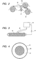
- FIG. 3 is a configuration diagram of a conductivity measuring apparatus for a charging roller according to the present invention.
- a direct current power source (6614C: manufactured by Agilent Technologies) 44 is connected to a conductive support of a charging roller 41, a voltage of 15V is applied to the conductive support, a free end of a cantilever 42 is brought into contact with a surface layer of the charging roller 41, and an electric current is measured under the conditions shown in Table 1 below. Electric current values at 100 points for the graphitized particle-derived convex portions, resin particle-derived convex portions and plane portions, respectively, are measured with varying the field of view to give an average value. It is desired that the graphitized particle-derived convex portions, CB-dispersed resin particle-derived convex portions and plane portions, as measurement targets, be measured in the same field of view.
- Table 1 Measurement mode contact(i) Cantilever CSC17 Measurement range 80 ⁇ m ⁇ 80 ⁇ m Scan rate 4Hz Applied voltage 15V
- the number of the CB-dispersed resin particle-derived convex portions is preferably 10 to 1,000, and the number of the graphitized particle-derived convex portions is preferably 100 to 10,000.
- thermosetting resin thermoplastic resin, rubber, and thermoplastic elastomer
- specific examples thereof include urethane resins, fluororesins, silicone resins, acrylic resins, polyamide resins, butyral resins, styrene-ethylene butylene-olefin copolymers, olefin-ethylene butylene-olefin copolymers. These may be used alone or in combination.
- thermosetting resins for their superiority in releasability to a photosensitive member and resistance to stain.
- the CB-dispersed resin particles dispersed in the surface layer are conductive particles comprised of a resin in which a carbon black is dispersed, and forming convex portions, serving as discharge points, on the surface layer.
- An average particle diameter of the CB-dispersed resin particles is 1 ⁇ m to 30 ⁇ m, especially 2 ⁇ m to 20 ⁇ m.
- a volume average particle diameter measured by the following method is employed as the average particle diameter of the CB-dispersed resin particles in the surface layer.
- the surface layer is cut out from arbitrarily selected points over a distance of 500 ⁇ m, on a 20 nm basis, by a focused ion beam (FB-2000C, manufactured by Hitachi Ltd.), and cross-sectional images thereof are photographed by an electron microscope. Images taken for the same particle are then combined at 20 nm-intervals, and a stereoscopic particle-shape is calculated.
- This work is carried out for arbitrarily selected 100 particles from resin particles, and these 100 particles are intended to measure the volume average particle diameter.
- An equivalent diameter of a sphere having the same volume calculated from the individual stereoscopic particle-shapes obtained is defined as a volume average particle diameter.
- An average value of volume average particle diameters of all the target particles is defined as an average particle diameter.
- 90% or more of the particles preferably have a particle diameter of from A/5 ⁇ m to 5A ⁇ m, more preferably from A/3 ⁇ m to 3A ⁇ m, provided that an average particle diameter of the CB-dispersed resin particles is represented by A ⁇ m.
- a particle size distribution of such resin particles is a distribution where an average particle diameter A ⁇ m is in the above range of volume average particle diameter.
- the ratio of the number of particles having a degree of circularity, as an indicator representing a spherical shape, of 0.9 or higher to the total number of resin particles dispersed in the surface layer is 80% or more. With the ratio of the particles having a degree of circularity 0.9 or higher being 80% or more, it is possible to prevent the occurrence of image nonuniformity like spotted stains resulting from smear of a surface of a charging roller.
- degree of circularity Circumferential length of a circle having an area identical to that of a projected particle image / Circumferential length of the projected particle image
- the degree of circularity is 1.000.
- the above-mentioned average particle diameter, particle size distribution and degree of circularity of the CB-dispersed resin particles are values obtained by measuring resin particles which have been dispersed in the surface layer. It is, however, also possible to employ a value obtained by using resin particles before being dispersed in the surface layer.
- 100 resin particles, in which secondarily aggregated particles have been removed so as to be primary particles alone, are observed by a microscope, such as a transmission electron microscope (TEM).
- TEM transmission electron microscope
- the resulting image is analyzed in a computer using image analysis software (Image-Pro Plus, manufactured by Planetron Inc.) to automatically calculate the degree of circularity through a count/size function.
- the volume resistivity of the CB-dispersed resin particles is preferably selected in view of the relationship with the volume resistivity of the graphitized particles.
- a volume resistivity of the CB-dispersed resin particles is 1.0 ⁇ 10 12 ⁇ cm to 1.0 ⁇ 10 3 ⁇ cm, especially 1.0 ⁇ 10 8 ⁇ cm to 1.0 ⁇ 10 5 ⁇ cm. This is because, with the volume resistivity being in the above range, it is possible to form discharge points with which a surface of an electrophotographic photosensitive member can be favorably contact-charged.
- volume resistivity of the CB-dispersed resin particles it is possible to employ a value measured when a voltage of 10V being applied to a sample under an environment of a temperature of 23°C and a relative humidity of 50%, using a resistance meter (trade name: LORESTA-GP, manufactured by Mitsubishi Chemical Co., Ltd.).
- LORESTA-GP trade name: LORESTA-GP, manufactured by Mitsubishi Chemical Co., Ltd.
- target samples for measuring the volume resistivity those compressed by applying a pressure of 10.1 MPa (102 kgf/cm 2 ) can be used.
- a resin constituting the CB-dispersed resin particles there may be exemplified acrylic resins, polybutadiene resins, polystyrene resins, phenol resins, polyamide resins, nylon resins, fluororesins, silicone resins, epoxy resins, and polyester resins.
- a carbon black to be dispersed in the resin there may be exemplified furnace black, thermal black, acetylene black, and KETJEN BLACK (trade name).
- furnace black thermal black, acetylene black, and KETJEN BLACK (trade name).
- these carbon blacks desirably have a primary particle diameter of 10 nm to 300 nm, because such carbon blacks can be uniformly dispersed in the resin.
- the average particle diameter of the carbon black a value measured according to the following method can be employed. From a cross-sectional image of resin particles photographed, 100 carbon black particles are arbitrarily selected. A projected area of each carbon black particle is determined, and a diameter equivalent to a circle having an area identical to that of the projected particle image is determined, and the result can be regarded as the average particle diameter of the carbon black. On this occasion, only particles having a circle-equivalent diameter in the range of from 5 nm to 500 nm are used for the measurement.
- the amount of the carbon black contained in the CB-dispersed resin particles is an amount required to give the above-mentioned volume resistivity to the CB-dispersed resin particles.
- the amount of the carbon black be suitably adjusted to be in the range of 1 part by mass to 15 parts by mass per 100 parts by mass of resin components of the resin particles. With the amount of the carbon black being in this range, it is possible to give the above-mentioned conductivity as well as a suitable hardness to the CB-dispersed resin particles.
- the following methods can be exemplified.
- the graphitized particles preferred is a substance which contains carbon atoms forming a laminar structure through SP 2 covalent bond and which has a half-value width ⁇ 1580 of a peak derived from graphite at 1,580 cm -1 in a Raman spectrum of 80 cm -1 or lower.
- the half-value width ⁇ 1580 is an indicator of the degree of graphitization and an indicator of broadening of graphite surface in its SP 2 orbit, resulting in an indicator of the conductivity of graphitized particles.
- More preferred range of the half-value width ⁇ 1580 is 30 cm -1 to 60 cm -1 . With the half-value width being in this range, the intensity of local electric fields at the photographic photosensitive member can be reduced as small as possible. As for ⁇ 1580 , a value measured under the conditions shown in Table 2 below can be employed.
- Table 2 Measurement sample Graphitized particles or a graphitized particle at a cross-section of a surface layer Measurement device Raman spectroscope (trade name: "LabRAM HR", manufactured by HORIBA JOBIN YVON Inc.) Laser He-Ne laser (peak wavelength: 632 nm) Filter D0.3 Hole 1000 ⁇ m Slit 100 ⁇ m Mid-spectrum 1500cm -1 Measured time length 1 second ⁇ 16 times Grating 1800 Objective lens ⁇ 50
- graphitized particles both natural graphite and artificial graphite can be used.
- a method of calcining particles of graphite precursor (graphitized particle precursor).
- the shape and conductivity of resultant graphitized particles can be controlled by selecting the type of graphitized particle precursor and calcination conditions.
- the shape of the resultant graphitized particles is more or less determined by the shape of the graphitized particle precursor.
- Specific examples of usable graphitized particle precursor include bulk-mesophase pitch, mesocarbon microbeads, phenol resins, phenol resin coated with mesophase, and coke coated with a pitch.
- the conductivity of resultant graphitized particles varies depending on the calcination conditions.
- graphitized particles obtained by calcination of graphitized particle precursor at higher temperature for a longer period of time will have higher conductivity. Further, the conductivity also varies depending on the chemical bond structure of the graphitized particle precursor used. Since the ease of change in crystallinity, such as hard-graphitization and easy-graphitization, differs depending on the graphitized particle precursor used, the same conductivity could not be obtained even under the same calcination conditions. Specific production methods of the graphitized particles will be described below, however, the graphitized particles used in the present invention are not limited to those obtained by these production methods.
- Graphitized particles obtained by calcination of coke coated with a pitch can be produced by adding a pitch to coke, molding the resulting product and then calcining the molded product.
- a pitch an oil residue in petroleum distillation, and a crude coke obtained by heating a coal tar pitch at a temperature of about 500°C, and the crude coke further heated at a temperature of 1,200°C or higher and 1,400°C or lower can be used.
- the pitch a pitch obtained as a distillation residue of tar can be used.
- a coke is finely pulverized and mixed with a pitch to prepare a mixture
- the mixture is kneaded under application of heat at a temperature of about 150°C
- the kneaded product is molded using a molding machine.
- the molded product is subjected to heat treatment at a temperature of 700°C or higher and 1,000°C or lower to impart thermal stability to the molded product.
- the molded product is subjected to heat treatment at a temperature of 2,600°C or higher and 3,000°C or lower to thereby obtain desired graphitized particles.
- it is desired to cover the molded product with packing-coke in order to avoid the molded product from being oxidized.
- a bulk-mesophase pitch can be obtained by extracting ⁇ -resin from coal-tar pitch by solvent fractionation and hydrogenating the ⁇ -resin to carry out heavy-duty treatment. Also, usable is mesophase pitch obtained by finely pulverizing the ⁇ -resin after its heavy-duty treatment and then removing the solvent-soluble matter using benzene or toluene.
- the bulk-mesophase pitch preferably contains 95% by weight or more of quinoline-soluble matter. If a bulk-mesophase pitch containing less than 95% by weight of the same is used, the interiors of particles can not easily be liquid-phase carbonized, and hence may come solid-phase carbonized to form carbonized particles whose shape is kept in a crushed state. In order to make the particles have a shape close to a spherical shape, it is more preferred to control the amount of the quinoline-soluble matter.
- the bulk-mesophase pitch is finely pulverized to obtain particles, and the particles obtained are subjected to heat treatment in air at 200°C or higher and 350°C or lower to carry out oxidation treatment lightly.
- This oxidation treatment makes the bulk-mesophase pitch particles infusible only at their surfaces, and the particles are prevented from melting or fusing at the time of heat treatment for graphitization in the subsequent step.
- the bulk-mesophase pitch particles having been subjected to oxidation treatment may preferably have an oxygen content of from 5% by mass or more and 15% by mass or less.
- the oxidized bulk-mesophase pitch particles have an oxygen content of 5% by mass or more, they can be prevented from fusing one another at the time of heat treatment. If the oxidized bulk-mesophase pitch particles have an oxygen content of 15% by mass or less, they can be prevented from being oxidized up to their interiors, and may be graphitized with their shape being in a crushed state, making it possible to obtain spherical particles.
- the bulk-mesophase pitch particles having been subjected to oxidation treatment are subjected to heat treatment at 1,000°C or higher and 3,500°C or lower in an inert atmosphere of nitrogen or argon, thereby obtaining the desired graphitized particles.
- mesocarbon microbeads there is, for example, a method in which coal type heavy oil or petroleum type heavy oil is subjected to heat treatment at a temperature of from 300°C or higher and 500°C or lower to effect polycondensation to form crude mesocarbon microbeads, then the reaction product is subjected to treatment such as filtration, sedimentation by leaving at rest, or centrifugation, to separate mesocarbon microbeads, and thereafter the mesocarbon microbeads are washed with a solvent such as benzene, toluene or xylene, and further dried to obtain mesocarbon microbeads.
- a solvent such as benzene, toluene or xylene
- the mesocarbon microbeads having been dried are kept mechanically primarily dispersed by a force mild enough not to break them. This is preferred in order to prevent particles from coalescing after graphitization and to obtain uniform particles.
- the mesocarbon microbeads having been thus kept primarily dispersed are subjected to primary heat treatment at a temperature of from 200°C or higher and 1,500°C or lower in an inert atmosphere to produce a carbonized product.
- the particles of the carbonized product thus obtained are mechanically dispersed by a force mild enough not to break them. This is preferred in order to prevent particles from coalescing after graphitization and to obtain uniform particles.
- the carbonized particles having been subjected to secondary dispersion treatment are subjected to secondary heat treatment at a temperature of from 1,000°C or higher and 3,500°C or lower in an inert atmosphere, thereby obtaining desired graphitized particles.
- a first element for controlling the height of each of the convex portions is the particle diameters of the CB-dispersed resin particles and the graphitized particles. That is, it is necessary for the CB-dispersed resin particles to select an average particle diameter greater than that of the graphitized particle diameter. More specifically, as the CB-dispersed resin particles, it is desired to use their particles having an average particle diameter of 0.5 ⁇ m or more, especially 3 ⁇ m or more greater than the average particle diameter of the graphitized particles.
- the upper limit of the difference in average particle diameter between the CB-dispersed resin particles and the graphitized particles is not particularly limited. The difference is, however, practically, 25 ⁇ m or less, especially, 15 ⁇ m or less.
- a second element for controlling the height of each of the convex portions is the preparation method of a surface layer-forming coating for use in formation of the surface layer. More specifically, in the preparation of a surface layer-forming coating, CB-dispersed resin particles and graphitized particles are dispersed in the binder resin. It is important, before/after this dispersion process, to secure the above-mentioned relationship of average particle diameters between the CB-dispersed resin particles and the graphitized particles. Under ordinary conditions for dispersing a filler in a binder for the purpose of effecting uniform dispersion, graphitized particles and CB-dispersed resin particles may undesirably crushed. In particular, graphitized particles are inherently brittle and easily crushed.
- the average particle diameter of graphitized particles could be significantly smaller than the original average particle diameter, or, on the contrary, excessively crushed particles could aggregate to each other to exist, as aggregates having a greater average particle diameter, in the surface layer-forming coating.
- the dispersion conditions are relaxed, such as shortening the dispersion time, to eliminate the possibility as much as possible that the graphitized particles and CB-dispersed resin particles could be crushed in the process of dispersing the graphitized particles and CB-dispersed resin particles in the binder resin to prepare the surface layer-forming coating.
- components other than the CB-dispersed resin particles and the graphitized particles for example, conductive fine particles, are mixed along with glass beads in the binder resin and dispersed over 24 hours to 36 hours, using a paint shaker dispersion machine.
- CB-dispersed resin particles and graphitized particles are added to the dispersion, and further dispersed.
- the dispersion time at this stage is one minute to 60 minutes, preferably 5 minutes to 10 minutes. With this, it is possible to prevent the graphitized particles and CB-dispersed resin particles from being crushed and to virtually secure the original relationship of average particle diameters between the CB-dispersed resin particles and the graphitized particles in the surface layer-forming coating.
- a third element for controlling the height of each of the convex portions is the thickness of the surface layer.
- the surface layer can be formed by applying, in a predetermined thickness, a surface layer-forming coating in which a binder resin, CB-dispersed resin particles and graphitized particles are dispersed, onto a support or an elastic layer formed on the support, by a known method. On this occasion, it is desired that the film thickness of the surface layer to the average particle diameter A ⁇ m of the CB-dispersed resin particles be A/3 to 10A, especially A/2 to 5A.
- the CB-dispersed resin particles and graphitized particles are embedded in the surface layer, and undesirably convex portions having desired heights may not be formed on the surface layer.
- each of the particle diameters of the CB-dispersed resin particles and the graphitized particles can affect the height of the CB-dispersed resin particle-derived convex portions and the height of the graphitized particle-derived convex portions.
- the amount of the CB-dispersed resin particles added to the surface layer coating is preferably 2 parts by mass to 80 parts by mass per 100 parts by mass of the binder resin, particularly preferably 5 parts by mass to 40 parts by mass.
- the amount of the graphitized particles added to the surface layer coating is preferably 0.5 parts by mass to 40 parts by mass per 100 parts by mass of the binder resin, particularly preferably 1 part by mass to 20 parts by mass.
- a ratio of the addition amount of the CB-dispersed resin particles to the addition amount of the graphitized particles is, in terms of mass ratio, from 0.1 to 10, more preferably from 0.5 to 2.
- the distance of the graphitized particle-derived convex portions is positive from a plane surface including each vertex of three CB-dispersed resin particle-derived convex portions adjacent to the graphitized particle-derived convex portions.
- the thickness of the surface layer can be controlled by suitably controlling the solid content, viscosity, and coating speed of the after-mentioned surface layer coating. The higher the solid content, the viscosity and the coating speed of the surface layer coating are, the thicker the film thickness can be.
- the values of the film thickness cross-sections of the surface layer are measured at three points in an axial direction, and three points in a circumferential direction, i.e., nine points in total. The cross-sections are observed by an optical microscope, an electron microscope or the like, and an average value of the measured values can be employed.
- the surface layer-forming coating there are, for example, slit coating, roll coating, ring coating, spray coating, and dip coating.
- dip coating the CB-dispersed resin particles and graphitized particles are less likely to be crushed in coating process. For this reason, the original relationship of average diameters between the CB-dispersed resin particle and the graphitized particles is easily secured, and thus dip coating is favorably employed.
- the surface layer may contain an ion conductive agent, and an electron conductive agent without departing from the spirit and scope of the appended claims. Further, for the purpose of uniformly improving the electric resistance of the surface layer, controlling the dielectric constant and the coefficient of elasticity thereof, insulating inorganic fine particles may be added to the surface layer.
- the inorganic fine particles particles of silica, and titanium oxide are preferred.
- a coating film after applying the surface layer coating is preferably heated, and exposed to ultraviolet ray or an electron beam, or subjected to moisture to accelerate crosslinking, because thereby it is possible to prevent resin particles and graphitized particles contained in the surface layer from falling off.
- the charging roller of the present invention may include layers having other functions, within the range not impairing the functions of the conductive support and the surface layer.
- layers having other functions within the range not impairing the functions of the conductive support and the surface layer.
- FIG. 4 there may be exemplified a configuration in which a conductive elastic layer 22 is provided between the conductive support 21 and the surface layer 23.
- epichlorohydrin rubber As a rubber constituting the conductive elastic layer 22, epichlorohydrin rubber, nitrile rubber (NBR), chloroprene rubber, urethane rubber, and silicone rubber are exemplified.
- thermoplastic elastomers As thermoplastic elastomers, styrenebutadiene-styrene-block copolymer (SBS), and styrene-ethylenebutylene-styrene block copolymer (SEBS) are exemplified.
- epichlorohydrin rubber is preferably used, because the rubber itself have conductivity of about 1 ⁇ 10 4 ⁇ cm to about 1 ⁇ 10 8 ⁇ cm in intermediately resistive regions and can prevent a variation in electric resistance of the conductive elastic layer.
- epichlorohydrin rubber examples include epichlorohydrin (EP) monopolymers, EP-ethylene oxide (EO) copolymers, EP-acryl glycidyl ether (AGE) copolymers, and EP-EO-AGE terpolymers.
- EP-EO-AGE terpolymers because the conductivity and processability of the conductive elastic layer can be controlled by controlling the polymerization degree and composition ratio of EP-EO-AGE terpolymers, and by using EP-EO-AGE terpolymers, an elastic layer having high mechanical strength and high conductivity can be obtained.
- typical compounding agents can be used within the range not impairing the properties, such as conductivity and mechanical strength, required for the charging roller of the present invention.
- a method of forming an elastic layer a method can be exemplified in which raw materials of these rubber and elastomer, and compounding agents to be compounded as required are kneaded and then molded.
- a method of kneading the raw materials a method of using a sealed kneader such as a Banbury mixer, intermix mixer, and pressurizing kneader; and a method of using an open kneader such as an open roll can be used.
- a molding method such as an extrusion molding, injection molding, and compression molding can be used.
- cross-head extrusion molding is preferred in which a kneaded product to be formed into an elastic layer is extruded together with the conductive support.
- a conductive support coated with an adhesive intended for adhesion with the elastic layer can also be used as required, within the range not losing high conductivity of the conductive support.
- the adhesive thermosetting resins, and thermoplastic resins containing conductive agent are exemplified. Specifically, a urethane resin adhesive, acrylic resin adhesive, polyester resin adhesive, polyether resin adhesive and epoxy resins adhesive can be used.
- a molded elastic layer may be ground to smooth the surface thereof and to precisely finish the shape thereof.
- traverse grinding mode a roller surface is ground by moving a short grindstone along the surface thereof.
- a surface of the elastic layer is ground using a wide-width grindstone, i.e., a grindstone having a width longer than the length of the elastic layer in a short period of time.
- the wide-width grinding mode is preferred.
- the elastic layer As the hardness of the elastic layer, it is appropriate for the elastic layer to have a microhardness of from 30° to 80°, more preferably from 45° to 65°. With the hardness of the elastic layer being within the above range, when the charging roller is contacted with a photographic photosensitive member, a distance between a vertex of the resin particle-derived convex portion and a vertex of the graphitized particle-derived convex portion can be maintained at a distance therebetween, in a state where the charging roller is not contacted with the photographic photosensitive member. With this, it is possible to prevent the occurrence of discharge nonuniformity due to the narrow nip width.
- the microhardness a value measured by the following method can be employed.
- a charging roller which is left standing in an environment of normal temperature and normal relative humidity (23°C/55%RH) for 12 hours or longer.
- the charging roller is intended to measure the microhardness by using a micro-area rubber hardness meter (ASKER MD-1: manufactured by Kobunshi Keiki Co., Ltd.) in a 10-N peak hold mode.
- ASKER MD-1 manufactured by Kobunshi Keiki Co., Ltd.
- the surface of the charging roller of the present invention preferably has such a ten-point average roughness (Rzjis) that a common charging roller has.
- the charging roller has a Rzjis of about 2 ⁇ m to about 30 ⁇ m and a Sm of about 15 ⁇ m to about 150 ⁇ m.
- Concerning the ten-point average roughness (Rzjis) and the average irregularity interval (Sm) of the surface of the charging roller values determined by a measurement method according to the surface roughness defined in JIS B0601-2001 can be employed. In the surface roughness measurement, a surface roughness meter (SE-3400, manufactured by Kosaka K.K.) can be used.
- Sm is an average interval measured between 10-point-irregularities (10-point concavo-convexes) in the measurement length.
- Rzjis and Sm the charging roller is randomly measured at six portions thereof, and an average value obtained from the measured results can be employed.
- the measurement length a standard measurement length defined in JIS B0601-2001 is used.
- the electric resistance of the charging roller may be a typical value of a contact type charging roller. More specifically, it is about 1 ⁇ 10 4 ⁇ to about 1 ⁇ 10 8 ⁇ in an environment of a temperature of 23°C and a relative humidity (RH) of 50%.
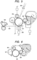
- FIG. 5 is a cross-sectional diagram of an electrophotographic apparatus using the charging roller of the present invention.
- the electrophotographic apparatus includes an electrophotographic photosensitive member 301, a charging roller 302 for charging the electrophotographic photosensitive member 301, an exposing device (not illustrated) which emits light 308 for forming a latent image, a developing device 303, a transfer device 305 for transferring an image onto a transfer material 304, a cleaning blade 307, and a fixing device 306.
- the electrophotographic photosensitive member 301 is of a rotatable drum type and has a photosensitive layer on a conductive support.
- the electrophotographic photosensitive member 301 is driven to rotate in a direction indicated by an arrow in the drawing, at a predetermined circumferential speed (process speed).
- the charging roller 302 is pressed by a predetermined pressing force of the electrophotographic photosensitive member 301 so as to be placed in contact therewith.
- the charging roller 302 is rotated followed by the rotation of the electrophotographic photosensitive member 301 and is adapted to charge the electrophotographic photosensitive member 301 with a predetermined electric potential by applying a direct current voltage from a charging power source 313.
- a latent image-forming device for forming a latent image on the electrophotographic photosensitive member 301 for example, an exposing device, such as a laser beam scanner, is used.
- the uniformly charged electrophotographic photosensitive member 301 is exposed to light correspondingly to image information, thereby forming an electrostatic latent image on the electrophotographic photosensitive member 301.
- the developing device 303 has a contact type developing roller which is disposed in contact with the electrophotographic photosensitive member 301.
- a toner which is electrostatically treated so as to have the same polarity as that of the electrophotographic photosensitive member is developed by a reversal processing to form the electrostatic latent image into a visible image.
- the transfer device 305 has a contact type transfer roller.
- the toner image is transferred from the electrophotographic photosensitive member 301 onto the transfer material 304 such as plain paper.
- the cleaning blade 307 mechanically scrapes off and collects untransferred residual toner which remains on the electrophotographic photosensitive member 301.
- the fixing device 306 is comprised of rolls which have been heated and fix the transferred toner image on the transfer material 304.
- FIG. 6 is a cross-sectional diagram of a process cartridge, in which the charging roller 302 of the present invention, the electrophotographic photosensitive member 301, the developing device 303, and the cleaning blade 307 are integrated into one unit, and the process cartridge is adapted to be detachably mounted on a main body of the electrophotographic apparatus.
- a ⁇ -resin that had been extracted from a coal tar pitch by solvent fractionation was hydrogenated.
- solvent-soluble matter was removed from the hydrogenated product thus obtained using toluene to yield a bulk-mesophase pitch.
- the bulk-mesophase pitch was mechanically pulverized so as to have a volume average particle diameter of approximately 3 ⁇ m.
- the pulverized product was oxidized by heating to a temperature of 270°C in the open air at a temperature increase rate of 300°C/h.
- the product was heated to 3,000°C in a nitrogen atmosphere at a temperature increase rate of 1,500°C /h and subjected to calcination at a temperature of 3,000°C for 15 minutes, and then subjected to classification, thereby obtaining Graphitized particle 1.
- Phenol resin particles having a volume average particle diameter of 10.0 ⁇ m was subjected to air classification to obtain phenol resin particles having a volume average particle diameter of 10.0 ⁇ m and a sharp particle size distribution.
- the phenol resin particles were thermally stabilized in the presence of an oxidizing atmosphere at 300°C for 1 hour and then calcined at 2,200°C.
- the resulting particles were subjected to air classification, thereby obtaining Graphitized particle 2.
- a flake graphite (trade name: X-10, produced by Ito Kokuen K.K.) was prepared as Graphitized particle 3.
- the resulting polyisocyanate prepolymer was found to have an isocyanate content of 8.73% and a viscosity of 1,500 cps (25°C).
- the resulting polyisocyanate prepolymer and a carbon black (#3350B: produced by Mitsubishi Chemical Co., Ltd.) (average particle diameter: 24 nm) were placed in water containing a suspension stabilizer (calcium phosphate), and were then mixed and stirred to obtain a suspension. Subsequently, the suspension was heated to initiate a reaction so as to be sufficiently reacted to produce CB-dispersed resin particles.
- Resin Particle 1 was found to have an average particle diameter of 5.8 ⁇ m.
- CB-Dispersed Resin Particles 2 to 8 each having an average particle diameter shown in Table 4 were produced in the same manner as in Production Example 3 except that the mixed amount of the carbon black was changed as shown in the following Table 4, and the concentration of the suspension stabilizer and the number of stirring revolutions were arbitrarily adjusted. Note that the mixed amount of carbon black shown in Table 4 is an amount expressed by part(s) by mass to 100 parts by mass of the polyisocyanate prepolymer.
- Mixture 1 The following materials were mixed, and dispersed by a viscomill type dispersing machine to obtain Mixture 1.
- the dispersion was carried out by using, as a dispersion medium, zirconia beads of 0.5 mm in diameter, and setting a circumferential speed to 10m/s for 60 hours.
- Mixture 1 and Mixture 2 were charged into a 2-litter-four-necked flask equipped with a high-speed stirring device (TK-type homomixer, manufactured by PRIMIX Corporation) and dispersed at 13,000 rpm to obtain a dispersion liquid. Then, this dispersion liquid was poured into a polymerization vessel equipped with a stirrer and a thermometer, the atmosphere in the polymerization vessel was replaced with nitrogen gas, and then the dispersion liquid was stirred at 55 rpm, at a reaction temperature of 60°C for 12 hours to complete suspension polymerization. The resulting reaction product was cooled and then subjected to filtration, washing, drying and classification, thereby obtaining Resin Particle 9.
- TK-type homomixer manufactured by PRIMIX Corporation
- CB-Dispersed Resin Particles 10 and 11 each having an average particle diameter shown in Table 4 were produced in the same manner as in Production Example 4 except that the mixed amount of the carbon black was changed as shown in the following Table 4, and the number of stirring revolutions was arbitrarily adjusted.
- the resulting kneaded product was cooled, and coarsely crushed by a hammer mill so as to have a particle diameter of 1 mm or smaller. Subsequently, the crushed particles were finely pulverized by a turbo mill (trade name: T-250, manufactured by Turbo Kogyo Co., Ltd.). The circumferential speed of the rotator was set to 115 m/s. Subsequently, the particles were made to have a substantially spherical shape, for 30 minutes, using a hybridizer (manufactured by Nara Machinery Co., Ltd.). Further, the particles were subjected to air classification, thereby obtaining CB-Dispersed Resin Particle 12.
- CB-Dispersed Resin Particles 13 and 14 each having an average particle diameter shown in Table 4 were produced in the same manner as in Production Example 5 except that the mixed amount of the carbon black was changed as shown in the following Table 4, and the number of revolutions of the rotator was adjusted.
- Table 4 CB-Dispersed Resin Particle Binder resin Mixed amount of carbon black (part by mass) Average particle diameter ( ⁇ m) 1 urethane resin 8 5.8 2 10.1 3 14 4 4 4 6.3 5 9.9 6 13.7 7 1 14.1 8 15 14.2
- acicular rutile type titanium oxide particles (average particle diameter: 15 nm, volume resistivity: 5.2 ⁇ 10 10 ⁇ cm), 110 g of isobutyltrimethoxysilane as a surface treatment agent, and 3,000 g of toluene as a solvent were mixed to prepare a slurry.
- the slurry was mixed for 30 minutes by a stirrer and then supplied to a visco mill filled with glass beads having an average particle diameter of 0.8 mm in an amount of 80% of the effective internal volume of the visco mill.
- the slurry was wet pulverized at a temperature of 35°C ⁇ 5°C.
- the slurry obtained by the wet pulverization was subjected to distillation under reduced pressure to remove the toluene therefrom, and the surface treatment agent was baked at 120°C for 2 hours.
- the baked particles were cooled to room temperature, and pulverized by a pin mill, thereby obtaining surface-treated titanium oxide fine particles having an average particle diameter of 17 nm.
- thermosetting adhesive (trade name: METALOCK U-20, produced by Toyo Kagaku Kenkyusho Co., Ltd.) and dried, and the cylindrical body was used as a conductive support.
- the following materials were kneaded for 10 minutes by a sealed mixer whose inside temperature was set to 50°C to prepare a raw-material compound.
- the conductive elastic layer compound was extruded together with the conductive support through a cross-head extruder so as to be molded in the form of a roller having an external diameter of about 9 mm.
- the molded conductive support was heated in an electric oven, the temperature thereof being maintained at 160°C for 1 hour to vulcanize the rubber and make the adhesive crosslinked. Both ends of the rubber were cut off so that the conductive support was exposed out of the rubber, and the length of the conductive elastic layer was 228 mm.
- the surface of the conductive support was ground so as to be formed in a roller having an external diameter of 8.5 mm, thereby obtaining an elastic layer.
- Coating material 1 The following materials were placed together with glass beads having an average particle diameter of 0.8 mm in a glass bottle and dispersed for 60 hours using a paint-shaker dispersing device to prepare Coating material 1.
- Coating material 2 The following materials were placed together with glass beads having an average particle diameter of 0.8 mm in a glass bottle and dispersed for 60 hours using a paint-shaker dispersing device to prepare Coating material 2.
- Coating material 3 The following materials were placed together with glass beads having an average particle diameter of 0.8 mm in a glass bottle and dispersed for 60 hours using a paint-shaker dispersing device to prepare Coating material 3.
- Coating material 4 was produced in the same manner as in Production Example 9 except that in the preparation of Coating material 1 in Production Example 9, the amount of the composite electronically conductive agent was changed to 14 parts by mass.
- Coating material 5 was produced in the same manner as in Production Example 9 except that in the preparation of Coating material 1 in Production Example 9, the amount of the composite electronically conductive agent was changed to 49 parts by mass.
- Coating material 6 was produced in the same manner as in Production Example 9 except that in the preparation of Coating material 1 in Production Example 9, the amount of the MIBK was changed to 220 parts by mass.
- Coating material 7 was produced in the same manner as in Production Example 9 except that in the preparation of Coating material 1 in Production Example 9, the amount of the MIBK was changed to 616 parts by mass.
- Coating material 1 After the following materials were added in Coating material 1, the materials were dispersed for 5 minutes by a paint-shaker dispersing device, and the glass beads were filtered out therefrom to obtain Surface Layer Coating material A.
- Surface Layer Coating material A was applied to a surface of the elastic layer formed in Production Example 8, by dip coating. Afterward, the coating was air dried at normal temperature for 30 minutes or more, heated in an electric oven at a temperature of 80°C for 1 hour and further heated at 160°C for 1 hour to make a film of Surface Layer Coating material A crosslinked, thereby forming a surface layer of 11.6 ⁇ m in thickness.
- a charging roller having an elastic layer and a surface layer on a conductive support was obtained.
- electric current values of I (A), I (B), and I (C) were measured by AFM.
- Image formation was carried out using the resulting charging roller in the following manner to evaluate the image formed.
- an electrophotographic apparatus LBP5400, manufactured by Canon Inc.
- LBP5400 manufactured by Canon Inc.
- An entire-blank image was output after setting V back (a voltage obtained by subtracting a voltage applied to a developing roller from a surface potential of the electrophotographic photosensitive member) to -20V and -70V. Since the toner placed in the electrophotographic apparatus is a negatively chargeable toner, the value of V back is usually set to about -70V to about -150V.
- V back With the voltage of V back being set to -20V and -70V, the toner is not developed on a surface of the electrophotographic photosensitive member under normal circumstances.
- Setting of V back to -20V was employed because this voltage setting correlates to the image density of non-latent image portions at from about -70V to about -150V, and a difference of image density in non-latent image portions can be clearly discriminated. It is presumed that a toner developed under this condition is developed because the toner is trapped by local electric fields across the surface of the electrophotographic photosensitive member due to nonuniformity of potential on the electrophotographic photosensitive member, which is produced by nonuniform discharge of a charging roller.
- the image was output by the remodeled machine thus configured, under an environment of a temperature of 15°C and a relative humidity of 10%.
- the degree of whiteness of the image output when setting the V back to -20V was measured using a whiteness photometer (trade name: TC-6DS/A, produced by Tokyo Denshoku Co., Ltd.) according to the method defined in JIS P8148.
- a difference in degree of whiteness indicating a degree of increased image density in non-latent image portions was calculated by subtracting the average value of five points of degree of whiteness of paper sheets after the image output, from the average value of five points of degree of whiteness of paper sheets before the image output.
- Image output was carried out in the same manner as in the measurement of the degree of increased image density in non-latent image portions except that the image output conditions were changed to the following conditions.
- a sheet of image was output using an image randomly printed at 1% area of an image formation area of A4-size paper, the operation of the electrophotographic apparatus was stopped, and 10 seconds later, the image forming operation was restarted. This operation was repeated, and 30,000 sheets of electrophotographic images were formed. Thereafter, electrophotographic images for evaluation were formed.
- the electrophotographic images for evaluation were halftone images (an image with an intermediate image density, which is a one-dot-width horizontal line in two-dot intervals was drawn in a direction perpendicular to the rotational direction of the electrophotographic photosensitive member). Printed images were evaluated according to the following criteria. The results are shown in Table 6.
- the Surface Layer Coating material B was applied to a surface of the elastic layer formed in Production Example 8, by ring coating. Afterward, the Surface Layer Coating material B was crosslinked using an electron-beam irradiating device (ELECTOROBEAM-C EC150/45/40 mA, manufactured by Iwasaki Denki K.K.), thereby obtaining a charging roller. More specifically, an electron beam was irradiated at an acceleration voltage of 150 kV, a radiation dose of 1,200 kGy, and an oxygen concentration of 300 ppm or lower. The resulting charging roller was evaluated in the same manner as in Example 1. The evaluation results are shown in Table 8.
- an electron beam was irradiated at an acceleration voltage of 150 kV, a radiation dose of 1,200 kGy, and an oxygen concentration of 300 ppm or lower.
- Example 17 Surface layer-forming coatings were prepared in the same manner as in Example 17 except that the Coating material, Graphitized particle, and CB-dispersed resin particle were changed to those shown in Table 7 below. Charging rollers were produced using these surface layer-forming coatings in the same manner as in Example 17. Each of the resulting charging rollers was evaluated in the same manner as in Example 17. The evaluation results are shown in Table 8 below.
Landscapes
- Physics & Mathematics (AREA)
- Engineering & Computer Science (AREA)
- General Physics & Mathematics (AREA)
- Plasma & Fusion (AREA)
- Computer Vision & Pattern Recognition (AREA)
- Electrostatic Charge, Transfer And Separation In Electrography (AREA)
Description
- The present invention relates to a charging roller which charges a subject to be charged by a contact charging method, a process cartridge, and an electrophotographic apparatus.
- Japanese Patent Application Laid-Open No.
2007-127777 -
JP2001092221 (A -
US7054579 (B2 ) relates to a charging member having a support and one or more cover layer(s), the ten-point average surface roughness of the surface of the charging member, the height of a hill of the surface of the charging member, the area at the part of the hill, and the area of a region surrounded by hills each having the height H (µm) and other hills each having a height of not less than the height H (µm), and not including any hills having a height of more than 0.5H (µm) satisfy a specific relationship. Also, a surface layer of the charging member contains high-molecular compound particles whose average particle diameter is between 2 and 50 µm and whose range of particle size distribution of average particle diameter is above 0mum and not greater than 7 µm. -
EP1355199 (A2 ) relates to a conductive member having a support and provided thereon at least one cover layer, the cover layer having a surface layer, and the surface layer containing fine particles. In the surface layer, fine particles present at the surface layer lower part corresponding to a range within 30% of the total layer thickness from the lowermost plane have an average particle diameter which is larger than the average particle diameter of fine particles present at the surface layer upper part corresponding to a range within 30% of the total layer thickness from the uppermost plane. - The present inventors have studied, based on the conventional technique, a charging roller having a surface layer which contains CB-dispersed resin particles and has, on its surface, convex portions derived from the CB-dispersed resin particles. As a result, the present inventors have found that the CB-dispersed resin particles forming the convex portions easily induce electrostatic discharge because the CB-dispersed resin particles are made conductive by carbon black, and thus such a charging roller exhibits a stable chargeability even if toner and external additives adhere on its surface according to the use thereof. It has also been found that on the other hand, "fogging" can take place on an electrophotographic image formed through a charging step using such a charging roller.
- Then, the present invention is directed to providing a charging roller having a stable chargeability and capable of preventing the occurrence of "fogging" on an electrophotographic image. The present invention is also directed to providing a process cartridge and an electrophotographic apparatus each capable of stably offering high-quality electrophotographic images.
- A charging roller according to the present invention is a contact charging type charging roller which includes a conductive support, and a surface layer, wherein the surface layer contains a binder, resin particles containing a carbon black dispersed in the binder, and graphitized particles dispersed in the binder; and the surface layer has, on its surface, convex portions derived from the resin particles, and convex portions derived from the graphitized particles, wherein the number of convex portions derived from the graphitized particles having a distance, as a positive value, from a plane surface including each vertex of three convex portions derived from the resin particles adjacent to one convex portion derived from the graphitized particles is 80% or more of the total number of the convex portions derived from the graphitized particles.
- An electrophotographic apparatus according to the present invention includes the charging roller and an electrophotographic photosensitive member which is arranged so as to be charged by the charging roller. Further, a process cartridge according to the present invention includes the charging roller, and the electrophotographic photosensitive member, wherein the process cartridge is adapted to be detachably mounted to a main body of an electrophotographic apparatus.
- The charging roller of the present invention can prevent the occurrence of lateral streak images due to a charging defect of a photosensitive member, which is caused by extraneous matter attached onto a surface of the charging roller and can prevent degradation of image quality with increased image density. The charging roller of the present invention is capable of stabilizing the discharge property even under application of a large output current load and is suitably used for electrophotographic apparatuses, in which attempts are made to achieve further higher image quality, higher speed performance, and longer lives.
-
-
FIGS. 1A and1B are diagrams illustrating a discharge state in a nip portion between a charging roller and an electrophotographic photosensitive member. -
FIG. 2 is a diagram illustrating a surface layer of a charging roller according to the present invention. -
FIG. 3 is a configuration diagram of a conductivity measuring apparatus for a charging roller according to the present invention. -
FIG. 4 is a cross-sectional diagram of a charging roller according to the present invention. -
FIG. 5 is a cross-sectional diagram of an electrophotographic apparatus using a charging roller according to the present invention. -
FIG. 6 is a cross-sectional diagram of a process cartridge provided with a charging roller according to the present invention. - The present inventors have presumed that the mechanism by which "fogging" occurs in an electrophotographic image by using a charging roller having, on its surface, convex portions derived from carbon black (CB) dispersed-resin particles as follows.
-
FIG. 1B is a diagram schematically illustrating a discharge state in a nip portion between a charging roller having, on its surface, convex portions derived from CB-dispersed resin particles (hereinafter, also referred to as "CB-dispersed resin particle-derived convex portion(s)"), and an electrophotographic photosensitive member. When asurface layer 101 of an electrophotographicphotosensitive member 105 is charged by a charging roller containing CB-dispersedresin particles 103,discharge 111 generated between a CB-dispersed resin particle-derivedconvex portion 107 and the electrophotographicphotosensitive member 105 greatly differs in intensity fromdischarge 113 generated between aplane portion 109, where no CB-dispersedresin particles 103 are provided, and the electrophotographicphotosensitive member 105. Therefore, on a surface of the electrophotographicphotosensitive member 105,areas area 115 is charged by discharge generated from the CB-dispersed resin particle-derived convex portions on the charging roller, and thearea 117 is charged by discharge generated from theplane portion 109 of the surface of the charging roller. Since a great difference in the electrical potential occurs between thearea 115 and thearea 117, a localelectric field 119 is induced between these areas. Under this condition, atoner 120 containing charged particles is trapped by the localelectric field 119 to travel along a surface of the electrophotographic photosensitive member. The present inventors considered that due to this traveling of the toner, the toner adheres onto non-latent image portions of the surface of electrophotographic photosensitive member, causing "fogging" in an electrophotographic image. - Based on the presumption, the present inventors thought that it would be possible to prevent "fogging" from adhering onto an electrophotographic photosensitive member by effecting electricity to be stably and appropriately discharged also from a plane portion between two CB-dispersed resin particle-derived convex portions while maintaining suitable discharge generated from the CB-dispersed resin particle-derived convex portions so as to weaken the intensity of the local electric fields generated at the surface of the electrophotographic photosensitive member. To this end, the present inventors produced a charging roller in which convex portions derived from graphitized particles (hereinafter, also referred to as "graphitized particle-derived convex portions") having a height lower than that of the CB-dispersed resin particle-derived convex portions are formed in the
plane portion 109. Then, the present inventors studied and examined the chargeability of the thus produced charging roller and "fogging" in electrophotographic images formed using the charging roller. As a result, the present inventors have found that the charging roller has a stable chargeability, and the occurrence of "fogging" is substantially reduced in electrophotographic images formed using the charging roller. The present invention has been accomplished based on the findings. - The reason why the occurrence of "fogging" onto electrophotographic images can be reduced by use of the charging roller of the present invention can be considered as follows.
FIG. 1A is a diagram schematically illustrating a discharge phenomenon generated in a nip portion formed between a charging roller according to the present invention and an electrophotographic photosensitive member. Asurface layer 201 of the charging roller contains CB-dispersedresin particles 103 andgraphitized particles 203 having a higher conductivity than the CB-dispersedresin particles 103. Thesurface layer 201 has, its surface, the CB-dispersed resin particle-derived convexportions 107, and graphitized particle-derivedconvex portions 205. Further, the graphitized particle-derivedconvex portions 205 are basically constructed so as not to come closer to the surface of the electrophotographicphotosensitive member 105 than the CB-dispersed resin particle-derivedconvex portions 107 do. In this case, from the graphitized particle-derivedconvex portions 205, adischarge 207 is generated which is more intensive than adischarge 113 generating from theplane portion 109 inFIG. 1B toward the electrophotographic photosensitive member, which is not as intensive as adischarge intensity 111 of the CB-dispersed resin particle-derivedconvex portions 107. Therefore, it is possible to prevent twoareas FIG. 1B , from being formed in the surface of the electrophotographicphotosensitive member 105. That is, it is possible to weaken the intensity of a localelectric field 209 which is formed at a surface of the electrophotographic photosensitive member. As a result, it is conceivable that the travel distance of atoner 120 traveling to the non-latent image portions along the surface of the electrophotographic photosensitive member can be made as short as possible, and adhesion of toner onto the non-latent image portions can be suppressed. - Hereinafter, the configuration of the charging roller of the present invention will be further described in detail.
- As materials of the conductive support, for example, metals such as iron, copper, stainless steel, aluminum, nickel, and alloys thereof are exemplified.
- The surface layer contains a binder and conductive resin particles containing a carbon black dispersed in the binder (CB-dispersed resin particles), and graphitized particles dispersed in the binder. Further, the surface layer has, on its surface, convex portions derived from the CB-dispersed resin particles (CB-dispersed resin particle-derived convex portions), and convex portions derived from the graphitized particles (graphitized particle-derived convex portions).
- As to the graphitized particle-derived convex portions, the number of convex portions derived from the graphitized particles having a distance, as a positive value, from a plane surface including each vertex of three convex portions derived from the resin particles adjacent to one convex portion derived from the graphitized particles is 80% or more of the total number of the convex portions derived from the graphitized particles. Here, as for a certain graphitized particle-derived convex portion, the description "having a distance, as "a positive value", from a plane surface including each vertex of three convex portions derived from the resin particles adjacent to the graphitized particle-derived convex portion" is defined as follows. In other words, it means that a vertex of the graphitized particle-derived convex portion is positioned lower than the plane surface including each vertex of three CB-dispersed resin particles-derived convexes adjacent to the graphitized particle-derived convex portion.
- One of the technical meanings of employing the above-mentioned configuration is to prevent the graphitized particle-derived convex portions from making contact with the surface of the electrophotographic photosensitive member. More specifically, the graphitized particles are more conductive than the CB-dispersed resin particles. Therefore, when the graphitized particle-derived convex portions directly come in contact with the surface of the electrophotographic photosensitive member, leakage may take place. In order to prevent the graphitized particle-derived convex portions from making contact with the surface of the electrophotographic photosensitive member has a technical meaning for avoiding the occurrence of leakage.
- In relation to the definition that the number of graphitized particle-derived convex portions that are not directly contacted with the surface of the electrophotographic photosensitive member is 80% or more of the total number of the graphitized particle-derived convex portions, the value "80%" itself has no critical meaning. It represents a specific numerical value and means that almost or all of the graphitized particle-derived convex portions are not in contact with the surface of the electrophotographic photosensitive member.
- The following describes a method of observing a relationship of the height of a graphitized particle-derived convex portion to the height of CB-dispersed resin particles lying around the graphitized particle-derived convex portion. As illustrated in
FIG. 2 , a laser beam is irradiated to convex portions of the surface layer using a laser microscope (not illustrated) to obtain a reflection spectrum, and graphitized particle-derivedconvex portion 31 is detected from the reflection spectrum. Then, CB-dispersed resin particle-derivedconvex portions 32 adjacent to the one graphitized particle-derivedconvex portion 31 are detected using the laser beam. The description "CB-dispersed resin particle-derived convex portions adjacent to the graphitized particle-derivedconvex portion 31" means three resin particle-derived convex portions each having a vertex, i.e., three vertexes, lying, in a dimensional distance, in the shortest length to the third shortest length from the vertex of the graphitized particle-derived convex portion. Next, aplane 32a including the three vertexes is determined, and adistance 33 between theplane 32a and the vertex of the graphitized particle-derivedconvex portion 31 is determined. Then, a surface (a plane portion) of the surface layer which is not provided with any convex portion is defined as a reference plane, the number of graphitized particle-derived convex portions which are placed, with respect to the reference plane, at a position lower than theplane 32a is determined, and a ratio of the number of the graphitized particle-derived convex portions thus determined to the total number of graphitized particle-derived convex portions is calculated. The resulting calculated value is 80% or more. When the ratio of the graphitized particle-derived convex portions that are placed at a position lower than theplane 32a is 80% or more, it is possible to prevent high-potential areas caused by high-intensity discharge from being formed on the surface of the electrophotographic photosensitive member, to prevent the occurrence of high-intensity electric field near the electrophotographic photosensitive member, and to prevent the occurrence of increased image density in non-latent image portions. - Hereinafter, a method of measuring graphitized particle-derived convex portions will be further described in detail. First, a surface of the surface layer in a field of view of 0.5 mm× 0.5 mm is observed by a laser microscope (trade name: LSM5 PASCAL, manufactured by Carl Zeiss AG). Whether the convex portions in the field of view are derived from CB-dispersed resin particles or derived from graphitized particles is identified by varying a wavelength of a laser to be excited and examining the given spectrum of the excitation light beam. Then, an x-y plane within the view is scanned with the laser to obtain dimensional image data, and graphitized particle-derived convex portions and CB-dispersed resin particle-derived convex portions are detected from the dimensional image data. Further, the focal point of the laser is moved in a Z-direction, and the scanning is repeated to obtain three-dimensional data. Next, a graphitized particle-derived convex portion is arbitrarily selected, and three CB-dispersed resin particle-derived convex portions adjacent to the graphitized particle-derived convex portion are determined. A distance of a plane including vertexes of the three CB-dispersed resin particle-derived convex portions, being away from vertex of the selected graphitized particle-derived convex portion is calculated from the three-dimensional data. This procedure is carried out for 10 graphitized particles in the field of view. Similarly to the above, the surface of the charging roller in a longitudinal direction is examined to measure for 10-field-of-views at substantially regular intervals. A distance of each vertex of the graphitized particle-derived convex portions in the thus obtained 100 portions in total being away from a plane including three vertexes of CB-dispersed resin particle-derived convex portions was examined. When the number of graphitized particle-derived convex portion is less than 100, the number of field of views is increased, and the measurement is repeated.
- When a vertex of a graphitized particle-derived convex portion lies, with respect to the reference plane, lower than the plane including three vertexes of CB-dispersed resin particle-derived convex portions adjacent to the graphitized particle-derived convex portion, the distance is defined as "positive", and when it lies, with respect to the reference plane, upper than the plane, the distance is defined as "negative". The number of the graphitized particle-derived convex portions with this distance being "positive" expressed in percentage is defined as "a ratio of positive graphitized particle-derived convex portions". In the charging member of the present invention, it is necessary that "the ratio of positive graphitized particle-derived convex portions" be set to 80% or more.
- The distance between the plane including three vertexes of adjacent CB-dispersed resin particle-derived convex portions and a graphitized particle-derived convex portion whose vertex lies at a position lower than the plane is preferably 0.5 µm to 15 µm, more preferably 3 µm to 10 µm. With the distance being in the above range, it is effective to prevent the occurrence of "fogging" in an electrophotographic image because the intensity of a local electric field is reduced.
- Preferably, the conductivities in the graphitized particle-derived convex portions and CB-dispersed resin particle-derived convex portions when a voltage of 15V being applied between a surface of the charging roller and the conductive support satisfy inequalities (1), (2) and (3) below.


- In the above inequalities, I(A) represents an average electric current value in CB-dispersed resin particle-derived convex portions; I(B) represents an average electric current value in graphitized particle-derived convex portions; and I(C) represents an average electric current value in plane portions. As described above, the conductivities are higher in order of the graphitized particle-derived convex portions, CB-dispersed resin particle-derived convex portions, and plane portions. When a voltage 15V is applied thereto, an average electric current value in graphitized particle-derived convex portions is 10nA or higher, preferably three times or more than and 100 times or less than the average electric current value in the CB-dispersed resin particle-derived convex portions. When the average electric current value in the graphitized particle-derived convex portions is 10nA or higher, the surface of a photographic photosensitive member can be charged by discharge generated from the graphitized particle-derived convex portions. By satisfying the inequality (2), a properly small amount of discharge is generated from the graphitized particle-derived convex portions, as compared to the discharge from the resin particle-derived convex portions, it is possible to obtain a further advantageous effect of reducing the occurrence of local electric fields across the surface of the electrophotographic photosensitive member, combined with the effect obtained from the heights of these convex portions.
- As the conductivities in the graphitized particle-derived convex portions, CB-dispersed resin particle-derived convex portions and plane portions, it is possible to employ conductivities measured, in a conductivity mode, by an atomic force microscope (AFM) (trade name: Q-SCOPE250, manufactured by Quesant instruments Corp.).
FIG. 3 is a configuration diagram of a conductivity measuring apparatus for a charging roller according to the present invention. A direct current power source (6614C: manufactured by Agilent Technologies) 44 is connected to a conductive support of a chargingroller 41, a voltage of 15V is applied to the conductive support, a free end of acantilever 42 is brought into contact with a surface layer of the chargingroller 41, and an electric current is measured under the conditions shown in Table 1 below. Electric current values at 100 points for the graphitized particle-derived convex portions, resin particle-derived convex portions and plane portions, respectively, are measured with varying the field of view to give an average value. It is desired that the graphitized particle-derived convex portions, CB-dispersed resin particle-derived convex portions and plane portions, as measurement targets, be measured in the same field of view.Table 1 Measurement mode contact(i) Cantilever CSC17 Measurement range 80µm × 80µm Scan rate 4Hz Applied voltage 15V - As each density of the CB-dispersed resin particle-derived convex portions and the graphitized particle-derived convex portions present on the surface of the surface layer in a 0.5 mm-square plane, the number of the CB-dispersed resin particle-derived convex portions is preferably 10 to 1,000, and the number of the graphitized particle-derived convex portions is preferably 100 to 10,000.
- The following describes materials constituting the above surface layer.
- As the binder, a thermosetting resin, thermoplastic resin, rubber, and thermoplastic elastomer can be used. Specific examples thereof include urethane resins, fluororesins, silicone resins, acrylic resins, polyamide resins, butyral resins, styrene-ethylene butylene-olefin copolymers, olefin-ethylene butylene-olefin copolymers. These may be used alone or in combination. Among these, preferred are thermosetting resins for their superiority in releasability to a photosensitive member and resistance to stain.
- The CB-dispersed resin particles dispersed in the surface layer are conductive particles comprised of a resin in which a carbon black is dispersed, and forming convex portions, serving as discharge points, on the surface layer. An average particle diameter of the CB-dispersed resin particles is 1 µm to 30 µm, especially 2 µm to 20 µm. Here, as the average particle diameter of the CB-dispersed resin particles in the surface layer, a volume average particle diameter measured by the following method is employed. The surface layer is cut out from arbitrarily selected points over a distance of 500 µm, on a 20 nm basis, by a focused ion beam (FB-2000C, manufactured by Hitachi Ltd.), and cross-sectional images thereof are photographed by an electron microscope. Images taken for the same particle are then combined at 20 nm-intervals, and a stereoscopic particle-shape is calculated. This work is carried out for arbitrarily selected 100 particles from resin particles, and these 100 particles are intended to measure the volume average particle diameter. An equivalent diameter of a sphere having the same volume calculated from the individual stereoscopic particle-shapes obtained is defined as a volume average particle diameter. An average value of volume average particle diameters of all the target particles is defined as an average particle diameter.
- In a particle size distribution of the CB-dispersed resin particles, 90% or more of the particles preferably have a particle diameter of from A/5 µm to 5A µm, more preferably from A/3 µm to 3A µm, provided that an average particle diameter of the CB-dispersed resin particles is represented by A µm. When the resin particles have a particle size distribution in the above-range, the intensity of discharge generated from the convex portions derived from the resin particles can be made more uniform. A particle size distribution of such resin particles is a distribution where an average particle diameter A µm is in the above range of volume average particle diameter.
- As the particle size distribution of the CB-dispersed resin particles, values calculated for the 100 measurement target particles which have been determined for their stereoscopic particle shapes by the above-mentioned method can be employed.
- The closer to a sphere the shape of the CB-dispersed resin particles, the smoother the surface of convex portions formed on a surface of the surface layer, the more difficult extraneous matter accumulates, and thus the more preferred. The ratio of the number of particles having a degree of circularity, as an indicator representing a spherical shape, of 0.9 or higher to the total number of resin particles dispersed in the surface layer is 80% or more. With the ratio of the particles having a degree of circularity 0.9 or higher being 80% or more, it is possible to prevent the occurrence of image nonuniformity like spotted stains resulting from smear of a surface of a charging roller. As the degree of circularity of resin particles dispersed in the surface layer, a value calculated from the following equation can be employed using the measurement results of the 100 particles that have been determined for their stereoscopic particle shapes by the above method.

- When the particle has a completely spherical shape, the degree of circularity is 1.000. The more complicated the surface shape, the lower the circularity.
- Note that the above-mentioned average particle diameter, particle size distribution and degree of circularity of the CB-dispersed resin particles are values obtained by measuring resin particles which have been dispersed in the surface layer. It is, however, also possible to employ a value obtained by using resin particles before being dispersed in the surface layer. First, 100 resin particles, in which secondarily aggregated particles have been removed so as to be primary particles alone, are observed by a microscope, such as a transmission electron microscope (TEM). The resulting image is analyzed in a computer using image analysis software (Image-Pro Plus, manufactured by Planetron Inc.) to automatically calculate the degree of circularity through a count/size function.
- The volume resistivity of the CB-dispersed resin particles is preferably selected in view of the relationship with the volume resistivity of the graphitized particles. A volume resistivity of the CB-dispersed resin particles is 1.0 × 10¹²Ω·cm to 1.0 × 10³Ω·cm, especially 1.0 × 10⁸Ω·cm to 1.0 × 10⁵Ω·cm. This is because, with the volume resistivity being in the above range, it is possible to form discharge points with which a surface of an electrophotographic photosensitive member can be favorably contact-charged. As the volume resistivity of the CB-dispersed resin particles, it is possible to employ a value measured when a voltage of 10V being applied to a sample under an environment of a temperature of 23°C and a relative humidity of 50%, using a resistance meter (trade name: LORESTA-GP, manufactured by Mitsubishi Chemical Co., Ltd.). As target samples for measuring the volume resistivity, those compressed by applying a pressure of 10.1 MPa (102 kgf/cm2) can be used.
- As a resin constituting the CB-dispersed resin particles, there may be exemplified acrylic resins, polybutadiene resins, polystyrene resins, phenol resins, polyamide resins, nylon resins, fluororesins, silicone resins, epoxy resins, and polyester resins. As a carbon black to be dispersed in the resin, there may be exemplified furnace black, thermal black, acetylene black, and KETJEN BLACK (trade name). As to the average particle diameter, these carbon blacks desirably have a primary particle diameter of 10 nm to 300 nm, because such carbon blacks can be uniformly dispersed in the resin. As the average particle diameter of the carbon black, a value measured according to the following method can be employed. From a cross-sectional image of resin particles photographed, 100 carbon black particles are arbitrarily selected. A projected area of each carbon black particle is determined, and a diameter equivalent to a circle having an area identical to that of the projected particle image is determined, and the result can be regarded as the average particle diameter of the carbon black. On this occasion, only particles having a circle-equivalent diameter in the range of from 5 nm to 500 nm are used for the measurement.
- The amount of the carbon black contained in the CB-dispersed resin particles is an amount required to give the above-mentioned volume resistivity to the CB-dispersed resin particles. Generally, it is desired that the amount of the carbon black be suitably adjusted to be in the range of 1 part by mass to 15 parts by mass per 100 parts by mass of resin components of the resin particles. With the amount of the carbon black being in this range, it is possible to give the above-mentioned conductivity as well as a suitable hardness to the CB-dispersed resin particles.
- As an example of the method of producing CB-dispersed resin particles, the following methods can be exemplified. There are, for example, a method in which a resin and a carbon black are kneaded so that the carbon black is dispersed in the resin, the dispersed product is cooled to be solidified, pulverized to form particles, the particles are mechanically processed and thermally treated so as to have a spherical shape, and then classified; and a method in which a polymerization initiator, a carbon black and other additives are added to a polymerizable monomer, the monomer composition is suspended, for polymerization, in an aqueous phase containing a dispersion stabilizer by a stirrer so as to have a predetermined particle diameter.
- As the graphitized particles, preferred is a substance which contains carbon atoms forming a laminar structure through SP2 covalent bond and which has a half-value width Δν1580 of a peak derived from graphite at 1,580 cm-1 in a Raman spectrum of 80 cm-1 or lower. The half-value width Δν1580 is an indicator of the degree of graphitization and an indicator of broadening of graphite surface in its SP2 orbit, resulting in an indicator of the conductivity of graphitized particles. The lower the half-value width Δν1580 is, the higher the degree of graphitization will be, the wider the graphite distribution will be, and the higher the conductivity will be. More preferred range of the half-value width Δν1580 is 30 cm-1 to 60 cm-1. With the half-value width being in this range, the intensity of local electric fields at the photographic photosensitive member can be reduced as small as possible. As for Δν1580, a value measured under the conditions shown in Table 2 below can be employed.
Table 2 Measurement sample Graphitized particles or a graphitized particle at a cross-section of a surface layer Measurement device Raman spectroscope (trade name: "LabRAM HR", manufactured by HORIBA JOBIN YVON Inc.) Laser He-Ne laser (peak wavelength: 632 nm) Filter D0.3 Hole 1000µm Slit 100µm Mid-spectrum 1500cm-1 Measured time length 1 second × 16 times Grating 1800 Objective lens ×50 - As the graphitized particles, both natural graphite and artificial graphite can be used. In order to produce artificial graphite, it is possible to use a method of calcining particles of graphite precursor (graphitized particle precursor). The shape and conductivity of resultant graphitized particles can be controlled by selecting the type of graphitized particle precursor and calcination conditions. The shape of the resultant graphitized particles is more or less determined by the shape of the graphitized particle precursor. Specific examples of usable graphitized particle precursor include bulk-mesophase pitch, mesocarbon microbeads, phenol resins, phenol resin coated with mesophase, and coke coated with a pitch. The conductivity of resultant graphitized particles varies depending on the calcination conditions. Generally, graphitized particles obtained by calcination of graphitized particle precursor at higher temperature for a longer period of time will have higher conductivity. Further, the conductivity also varies depending on the chemical bond structure of the graphitized particle precursor used. Since the ease of change in crystallinity, such as hard-graphitization and easy-graphitization, differs depending on the graphitized particle precursor used, the same conductivity could not be obtained even under the same calcination conditions. Specific production methods of the graphitized particles will be described below, however, the graphitized particles used in the present invention are not limited to those obtained by these production methods.
- Graphitized particles obtained by calcination of coke coated with a pitch can be produced by adding a pitch to coke, molding the resulting product and then calcining the molded product. As the cokes, an oil residue in petroleum distillation, and a crude coke obtained by heating a coal tar pitch at a temperature of about 500°C, and the crude coke further heated at a temperature of 1,200°C or higher and 1,400°C or lower can be used. As the pitch, a pitch obtained as a distillation residue of tar can be used.
- As a method for obtaining graphitized particles using these raw materials, first, a coke is finely pulverized and mixed with a pitch to prepare a mixture, the mixture is kneaded under application of heat at a temperature of about 150°C, and the kneaded product is molded using a molding machine. The molded product is subjected to heat treatment at a temperature of 700°C or higher and 1,000°C or lower to impart thermal stability to the molded product. Next, the molded product is subjected to heat treatment at a temperature of 2,600°C or higher and 3,000°C or lower to thereby obtain desired graphitized particles. In the heat treatment, it is desired to cover the molded product with packing-coke in order to avoid the molded product from being oxidized.
- A bulk-mesophase pitch can be obtained by extracting β-resin from coal-tar pitch by solvent fractionation and hydrogenating the β-resin to carry out heavy-duty treatment. Also, usable is mesophase pitch obtained by finely pulverizing the β-resin after its heavy-duty treatment and then removing the solvent-soluble matter using benzene or toluene. The bulk-mesophase pitch preferably contains 95% by weight or more of quinoline-soluble matter. If a bulk-mesophase pitch containing less than 95% by weight of the same is used, the interiors of particles can not easily be liquid-phase carbonized, and hence may come solid-phase carbonized to form carbonized particles whose shape is kept in a crushed state. In order to make the particles have a shape close to a spherical shape, it is more preferred to control the amount of the quinoline-soluble matter.
- As a method for obtaining graphitized particles using the mesophase pitch, the bulk-mesophase pitch is finely pulverized to obtain particles, and the particles obtained are subjected to heat treatment in air at 200°C or higher and 350°C or lower to carry out oxidation treatment lightly. This oxidation treatment makes the bulk-mesophase pitch particles infusible only at their surfaces, and the particles are prevented from melting or fusing at the time of heat treatment for graphitization in the subsequent step. The bulk-mesophase pitch particles having been subjected to oxidation treatment may preferably have an oxygen content of from 5% by mass or more and 15% by mass or less. If the oxidized bulk-mesophase pitch particles have an oxygen content of 5% by mass or more, they can be prevented from fusing one another at the time of heat treatment. If the oxidized bulk-mesophase pitch particles have an oxygen content of 15% by mass or less, they can be prevented from being oxidized up to their interiors, and may be graphitized with their shape being in a crushed state, making it possible to obtain spherical particles. Next, the bulk-mesophase pitch particles having been subjected to oxidation treatment are subjected to heat treatment at 1,000°C or higher and 3,500°C or lower in an inert atmosphere of nitrogen or argon, thereby obtaining the desired graphitized particles.
- As a method for obtaining mesocarbon microbeads, for example, there is, for example, a method in which coal type heavy oil or petroleum type heavy oil is subjected to heat treatment at a temperature of from 300°C or higher and 500°C or lower to effect polycondensation to form crude mesocarbon microbeads, then the reaction product is subjected to treatment such as filtration, sedimentation by leaving at rest, or centrifugation, to separate mesocarbon microbeads, and thereafter the mesocarbon microbeads are washed with a solvent such as benzene, toluene or xylene, and further dried to obtain mesocarbon microbeads.
- As a method for obtaining graphitized particles using the mesocarbon microbeads, the mesocarbon microbeads having been dried are kept mechanically primarily dispersed by a force mild enough not to break them. This is preferred in order to prevent particles from coalescing after graphitization and to obtain uniform particles. The mesocarbon microbeads having been thus kept primarily dispersed are subjected to primary heat treatment at a temperature of from 200°C or higher and 1,500°C or lower in an inert atmosphere to produce a carbonized product. The particles of the carbonized product thus obtained are mechanically dispersed by a force mild enough not to break them. This is preferred in order to prevent particles from coalescing after graphitization and to obtain uniform particles. The carbonized particles having been subjected to secondary dispersion treatment are subjected to secondary heat treatment at a temperature of from 1,000°C or higher and 3,500°C or lower in an inert atmosphere, thereby obtaining desired graphitized particles.
- In the surface layer of the present invention, it is important to control the height of the CB-dispersed resin particle-derived convex portions and graphitized particle-derived convex portions. A first element for controlling the height of each of the convex portions is the particle diameters of the CB-dispersed resin particles and the graphitized particles. That is, it is necessary for the CB-dispersed resin particles to select an average particle diameter greater than that of the graphitized particle diameter. More specifically, as the CB-dispersed resin particles, it is desired to use their particles having an average particle diameter of 0.5 µm or more, especially 3 µm or more greater than the average particle diameter of the graphitized particles. The upper limit of the difference in average particle diameter between the CB-dispersed resin particles and the graphitized particles is not particularly limited. The difference is, however, practically, 25 µm or less, especially, 15 µm or less.
- A second element for controlling the height of each of the convex portions is the preparation method of a surface layer-forming coating for use in formation of the surface layer. More specifically, in the preparation of a surface layer-forming coating, CB-dispersed resin particles and graphitized particles are dispersed in the binder resin. It is important, before/after this dispersion process, to secure the above-mentioned relationship of average particle diameters between the CB-dispersed resin particles and the graphitized particles. Under ordinary conditions for dispersing a filler in a binder for the purpose of effecting uniform dispersion, graphitized particles and CB-dispersed resin particles may undesirably crushed. In particular, graphitized particles are inherently brittle and easily crushed. There are possibilities that the average particle diameter of graphitized particles could be significantly smaller than the original average particle diameter, or, on the contrary, excessively crushed particles could aggregate to each other to exist, as aggregates having a greater average particle diameter, in the surface layer-forming coating. In light of the above, the dispersion conditions are relaxed, such as shortening the dispersion time, to eliminate the possibility as much as possible that the graphitized particles and CB-dispersed resin particles could be crushed in the process of dispersing the graphitized particles and CB-dispersed resin particles in the binder resin to prepare the surface layer-forming coating. More specifically, first, components other than the CB-dispersed resin particles and the graphitized particles, for example, conductive fine particles, are mixed along with glass beads in the binder resin and dispersed over 24 hours to 36 hours, using a paint shaker dispersion machine. Next, CB-dispersed resin particles and graphitized particles are added to the dispersion, and further dispersed. The dispersion time at this stage is one minute to 60 minutes, preferably 5 minutes to 10 minutes. With this, it is possible to prevent the graphitized particles and CB-dispersed resin particles from being crushed and to virtually secure the original relationship of average particle diameters between the CB-dispersed resin particles and the graphitized particles in the surface layer-forming coating.
- A third element for controlling the height of each of the convex portions is the thickness of the surface layer. The surface layer can be formed by applying, in a predetermined thickness, a surface layer-forming coating in which a binder resin, CB-dispersed resin particles and graphitized particles are dispersed, onto a support or an elastic layer formed on the support, by a known method. On this occasion, it is desired that the film thickness of the surface layer to the average particle diameter A µm of the CB-dispersed resin particles be A/3 to 10A, especially A/2 to 5A. When the surface layer is made excessively thick, the CB-dispersed resin particles and graphitized particles are embedded in the surface layer, and undesirably convex portions having desired heights may not be formed on the surface layer. With the thickness of the surface layer being in the above range, each of the particle diameters of the CB-dispersed resin particles and the graphitized particles can affect the height of the CB-dispersed resin particle-derived convex portions and the height of the graphitized particle-derived convex portions. Here, the amount of the CB-dispersed resin particles added to the surface layer coating is preferably 2 parts by mass to 80 parts by mass per 100 parts by mass of the binder resin, particularly preferably 5 parts by mass to 40 parts by mass. The amount of the graphitized particles added to the surface layer coating is preferably 0.5 parts by mass to 40 parts by mass per 100 parts by mass of the binder resin, particularly preferably 1 part by mass to 20 parts by mass. Then, a ratio of the addition amount of the CB-dispersed resin particles to the addition amount of the graphitized particles is, in terms of mass ratio, from 0.1 to 10, more preferably from 0.5 to 2. With this, The CB-dispersed resin particle-derived convex portions can be allowed to exist around almost all the graphitized particle-derived convex portions. As a result, for almost all the graphitized particle-derived convex portions, the distance of the graphitized particle-derived convex portions is positive from a plane surface including each vertex of three CB-dispersed resin particle-derived convex portions adjacent to the graphitized particle-derived convex portions. The thickness of the surface layer can be controlled by suitably controlling the solid content, viscosity, and coating speed of the after-mentioned surface layer coating. The higher the solid content, the viscosity and the coating speed of the surface layer coating are, the thicker the film thickness can be. As the values of the film thickness, cross-sections of the surface layer are measured at three points in an axial direction, and three points in a circumferential direction, i.e., nine points in total. The cross-sections are observed by an optical microscope, an electron microscope or the like, and an average value of the measured values can be employed.
- As a coating method of the surface layer-forming coating, there are, for example, slit coating, roll coating, ring coating, spray coating, and dip coating. Particularly, when dip coating is employed, the CB-dispersed resin particles and graphitized particles are less likely to be crushed in coating process. For this reason, the original relationship of average diameters between the CB-dispersed resin particle and the graphitized particles is easily secured, and thus dip coating is favorably employed.
- The surface layer may contain an ion conductive agent, and an electron conductive agent without departing from the spirit and scope of the appended claims. Further, for the purpose of uniformly improving the electric resistance of the surface layer, controlling the dielectric constant and the coefficient of elasticity thereof, insulating inorganic fine particles may be added to the surface layer. As the inorganic fine particles, particles of silica, and titanium oxide are preferred.
- A coating film after applying the surface layer coating is preferably heated, and exposed to ultraviolet ray or an electron beam, or subjected to moisture to accelerate crosslinking, because thereby it is possible to prevent resin particles and graphitized particles contained in the surface layer from falling off.
- The charging roller of the present invention may include layers having other functions, within the range not impairing the functions of the conductive support and the surface layer. By way of example, as illustrated in
FIG. 4 , there may be exemplified a configuration in which a conductiveelastic layer 22 is provided between theconductive support 21 and thesurface layer 23. - As a rubber constituting the conductive
elastic layer 22, epichlorohydrin rubber, nitrile rubber (NBR), chloroprene rubber, urethane rubber, and silicone rubber are exemplified. As thermoplastic elastomers, styrenebutadiene-styrene-block copolymer (SBS), and styrene-ethylenebutylene-styrene block copolymer (SEBS) are exemplified. Among these, epichlorohydrin rubber is preferably used, because the rubber itself have conductivity of about 1 × 10⁴ Ω·cm to about 1 × 10⁸Ω·cm in intermediately resistive regions and can prevent a variation in electric resistance of the conductive elastic layer. Specific examples of the epichlorohydrin rubber include epichlorohydrin (EP) monopolymers, EP-ethylene oxide (EO) copolymers, EP-acryl glycidyl ether (AGE) copolymers, and EP-EO-AGE terpolymers. Among these, particularly preferred are EP-EO-AGE terpolymers, because the conductivity and processability of the conductive elastic layer can be controlled by controlling the polymerization degree and composition ratio of EP-EO-AGE terpolymers, and by using EP-EO-AGE terpolymers, an elastic layer having high mechanical strength and high conductivity can be obtained. In the conductive elastic layer, typical compounding agents can be used within the range not impairing the properties, such as conductivity and mechanical strength, required for the charging roller of the present invention. - As a method of forming an elastic layer, a method can be exemplified in which raw materials of these rubber and elastomer, and compounding agents to be compounded as required are kneaded and then molded. As a method of kneading the raw materials, a method of using a sealed kneader such as a Banbury mixer, intermix mixer, and pressurizing kneader; and a method of using an open kneader such as an open roll can be used. As a method of forming a kneaded product on the conductive support, a molding method, such as an extrusion molding, injection molding, and compression molding can be used. In consideration of working efficiency, cross-head extrusion molding is preferred in which a kneaded product to be formed into an elastic layer is extruded together with the conductive support. As the conductive support, a conductive support coated with an adhesive intended for adhesion with the elastic layer can also be used as required, within the range not losing high conductivity of the conductive support. As the adhesive, thermosetting resins, and thermoplastic resins containing conductive agent are exemplified. Specifically, a urethane resin adhesive, acrylic resin adhesive, polyester resin adhesive, polyether resin adhesive and epoxy resins adhesive can be used. Afterward, when it is necessary to carry out crosslinking of the elastic layer, it is desired that the elastic layer undergo a crosslinking process, such as crosslinking during molding, crosslinking using a vulcanizer, continuous crosslinking, crosslinking by far/near-infrared radiation, and crosslinking by induction heating. A molded elastic layer may be ground to smooth the surface thereof and to precisely finish the shape thereof. As the grinding method, traverse grinding mode, and wide-width grinding mode can be employed. In the traverse grinding mode, a roller surface is ground by moving a short grindstone along the surface thereof. In contrast, in the wide-width grinding mode, a surface of the elastic layer is ground using a wide-width grindstone, i.e., a grindstone having a width longer than the length of the elastic layer in a short period of time. In terms of the working efficiency, the wide-width grinding mode is preferred.
- As the hardness of the elastic layer, it is appropriate for the elastic layer to have a microhardness of from 30° to 80°, more preferably from 45° to 65°. With the hardness of the elastic layer being within the above range, when the charging roller is contacted with a photographic photosensitive member, a distance between a vertex of the resin particle-derived convex portion and a vertex of the graphitized particle-derived convex portion can be maintained at a distance therebetween, in a state where the charging roller is not contacted with the photographic photosensitive member. With this, it is possible to prevent the occurrence of discharge nonuniformity due to the narrow nip width. Here, as the microhardness, a value measured by the following method can be employed. A charging roller, which is left standing in an environment of normal temperature and normal relative humidity (23°C/55%RH) for 12 hours or longer. The charging roller is intended to measure the microhardness by using a micro-area rubber hardness meter (ASKER MD-1: manufactured by Kobunshi Keiki Co., Ltd.) in a 10-N peak hold mode.
- The surface of the charging roller of the present invention preferably has such a ten-point average roughness (Rzjis) that a common charging roller has. Specifically, the charging roller has a Rzjis of about 2 µm to about 30 µm and a Sm of about 15 µm to about 150 µm. Concerning the ten-point average roughness (Rzjis) and the average irregularity interval (Sm) of the surface of the charging roller, values determined by a measurement method according to the surface roughness defined in JIS B0601-2001 can be employed. In the surface roughness measurement, a surface roughness meter (SE-3400, manufactured by Kosaka K.K.) can be used. Here, Sm is an average interval measured between 10-point-irregularities (10-point concavo-convexes) in the measurement length. As values of Rzjis and Sm, the charging roller is randomly measured at six portions thereof, and an average value obtained from the measured results can be employed. As the measurement length, a standard measurement length defined in JIS B0601-2001 is used. The electric resistance of the charging roller may be a typical value of a contact type charging roller. More specifically, it is about 1 × 10⁴Ω to about 1 × 10⁸Ω in an environment of a temperature of 23°C and a relative humidity (RH) of 50%.
-
FIG. 5 is a cross-sectional diagram of an electrophotographic apparatus using the charging roller of the present invention. The electrophotographic apparatus includes an electrophotographicphotosensitive member 301, a chargingroller 302 for charging the electrophotographicphotosensitive member 301, an exposing device (not illustrated) which emits light 308 for forming a latent image, a developingdevice 303, atransfer device 305 for transferring an image onto atransfer material 304, acleaning blade 307, and afixing device 306. The electrophotographicphotosensitive member 301 is of a rotatable drum type and has a photosensitive layer on a conductive support. The electrophotographicphotosensitive member 301 is driven to rotate in a direction indicated by an arrow in the drawing, at a predetermined circumferential speed (process speed). The chargingroller 302 is pressed by a predetermined pressing force of the electrophotographicphotosensitive member 301 so as to be placed in contact therewith. The chargingroller 302 is rotated followed by the rotation of the electrophotographicphotosensitive member 301 and is adapted to charge the electrophotographicphotosensitive member 301 with a predetermined electric potential by applying a direct current voltage from a charging power source 313. As a latent image-forming device for forming a latent image on the electrophotographicphotosensitive member 301, for example, an exposing device, such as a laser beam scanner, is used. The uniformly charged electrophotographicphotosensitive member 301 is exposed to light correspondingly to image information, thereby forming an electrostatic latent image on the electrophotographicphotosensitive member 301. The developingdevice 303 has a contact type developing roller which is disposed in contact with the electrophotographicphotosensitive member 301. A toner which is electrostatically treated so as to have the same polarity as that of the electrophotographic photosensitive member is developed by a reversal processing to form the electrostatic latent image into a visible image. Thetransfer device 305 has a contact type transfer roller. The toner image is transferred from the electrophotographicphotosensitive member 301 onto thetransfer material 304 such as plain paper. Thecleaning blade 307 mechanically scrapes off and collects untransferred residual toner which remains on the electrophotographicphotosensitive member 301. The fixingdevice 306 is comprised of rolls which have been heated and fix the transferred toner image on thetransfer material 304. -
FIG. 6 is a cross-sectional diagram of a process cartridge, in which the chargingroller 302 of the present invention, the electrophotographicphotosensitive member 301, the developingdevice 303, and thecleaning blade 307 are integrated into one unit, and the process cartridge is adapted to be detachably mounted on a main body of the electrophotographic apparatus. - Hereinafter, the present invention will be further described in detail with reference to specific examples.
- A β-resin that had been extracted from a coal tar pitch by solvent fractionation was hydrogenated. Next, solvent-soluble matter was removed from the hydrogenated product thus obtained using toluene to yield a bulk-mesophase pitch. The bulk-mesophase pitch was mechanically pulverized so as to have a volume average particle diameter of approximately 3 µm. Afterward, the pulverized product was oxidized by heating to a temperature of 270°C in the open air at a temperature increase rate of 300°C/h. Subsequently, the product was heated to 3,000°C in a nitrogen atmosphere at a temperature increase rate of 1,500°C /h and subjected to calcination at a temperature of 3,000°C for 15 minutes, and then subjected to classification, thereby obtaining Graphitized particle 1.
- Phenol resin particles having a volume average particle diameter of 10.0 µm was subjected to air classification to obtain phenol resin particles having a volume average particle diameter of 10.0 µm and a sharp particle size distribution. The phenol resin particles were thermally stabilized in the presence of an oxidizing atmosphere at 300°C for 1 hour and then calcined at 2,200°C. The resulting particles were subjected to air classification, thereby obtaining Graphitized particle 2.
- A flake graphite (trade name: X-10, produced by Ito Kokuen K.K.) was prepared as Graphitized particle 3.
- Average particle diameters and Δν1580 of Graphitized particles 1 to 3 measured by the method described above are shown in Table 3.
Table 3 Graphitized particle No. Average Particle Diameter (µm) Δν1580cm-1 Graphitized particle 1 3.3 32 Graphitized particle 2 9.8 69 Graphitized particle 3 10.2 18 - A 2L-volumetric autoclave, with the atmosphere therein sufficiently replaced with nitrogen gas and dried, was charged with the following materials, and further sufficiently replaced with nitrogen gas from above. Then, the materials were sealed off and mixed with stirring at a temperature of 120°C for 20 hours to react with each other. Thereafter, unreacted HDI was removed from the reaction product under reduced pressure, and toluene was added to the reaction product to obtain a polyisocyanate prepolymer having a nonvolatile content of 90% by mass.
- polyol (ADEKA POLYETHER G-700: produced by Asahi Denka Kogyo K.K.)(hydroxyl value: 225 mg/KOHg): 75 parts by mass
- hexamethylenediisocyanate (HDI): 100 parts by mass
- The resulting polyisocyanate prepolymer was found to have an isocyanate content of 8.73% and a viscosity of 1,500 cps (25°C). Next, the resulting polyisocyanate prepolymer and a carbon black (#3350B: produced by Mitsubishi Chemical Co., Ltd.) (average particle diameter: 24 nm) were placed in water containing a suspension stabilizer (calcium phosphate), and were then mixed and stirred to obtain a suspension. Subsequently, the suspension was heated to initiate a reaction so as to be sufficiently reacted to produce CB-dispersed resin particles. Afterwards, the CB-dispersed resin particles were separated into a liquid phase and a solid phase, and the solid phase was washed to remove the suspension stabilizer adhering on the CB-dispersed resin particles, and was dried, thereby obtaining Resin Particle 1. Resin Particle 1 was found to have an average particle diameter of 5.8 µm.
- CB-Dispersed Resin Particles 2 to 8 each having an average particle diameter shown in Table 4 were produced in the same manner as in Production Example 3 except that the mixed amount of the carbon black was changed as shown in the following Table 4, and the concentration of the suspension stabilizer and the number of stirring revolutions were arbitrarily adjusted. Note that the mixed amount of carbon black shown in Table 4 is an amount expressed by part(s) by mass to 100 parts by mass of the polyisocyanate prepolymer.
- The following materials were mixed, and dispersed by a viscomill type dispersing machine to obtain Mixture 1. The dispersion was carried out by using, as a dispersion medium, zirconia beads of 0.5 mm in diameter, and setting a circumferential speed to 10m/s for 60 hours.
- methyl methacrylate: 100 parts by mass
- carbon black (average particle diameter: 28 nm, pH = 6.0): 4 parts by mass
- ethylene glycol dimethacrylate: 0.1 parts by mass
- benzoyl peroxide: 0.5 parts by mass
- Meanwhile, the following materials were mixed to prepare Mixture 2.
- ion exchanged water: 400 parts by mass
- polyvinyl alcohol (saponification degree: 85%): 8 parts by mass
- sodium lauryl sulfate: 0.04 parts by mass
- Next, Mixture 1 and Mixture 2 were charged into a 2-litter-four-necked flask equipped with a high-speed stirring device (TK-type homomixer, manufactured by PRIMIX Corporation) and dispersed at 13,000 rpm to obtain a dispersion liquid. Then, this dispersion liquid was poured into a polymerization vessel equipped with a stirrer and a thermometer, the atmosphere in the polymerization vessel was replaced with nitrogen gas, and then the dispersion liquid was stirred at 55 rpm, at a reaction temperature of 60°C for 12 hours to complete suspension polymerization. The resulting reaction product was cooled and then subjected to filtration, washing, drying and classification, thereby obtaining Resin Particle 9.
- CB-Dispersed Resin Particles 10 and 11 each having an average particle diameter shown in Table 4 were produced in the same manner as in Production Example 4 except that the mixed amount of the carbon black was changed as shown in the following Table 4, and the number of stirring revolutions was arbitrarily adjusted.
- The following materials were kneaded for 2 hours by a sealed mixer.
- styrene-dimethylaminoethylmethacrylate-divinylbenzene copolymer (copolymerization ratio = 90:10:0.05): 100 parts by mass
- carbon black (average particle diameter: 122 nm, pH = 7.5): 4 parts by mass
- The resulting kneaded product was cooled, and coarsely crushed by a hammer mill so as to have a particle diameter of 1 mm or smaller. Subsequently, the crushed particles were finely pulverized by a turbo mill (trade name: T-250, manufactured by Turbo Kogyo Co., Ltd.). The circumferential speed of the rotator was set to 115 m/s. Subsequently, the particles were made to have a substantially spherical shape, for 30 minutes, using a hybridizer (manufactured by Nara Machinery Co., Ltd.). Further, the particles were subjected to air classification, thereby obtaining CB-Dispersed Resin Particle 12.
- CB-Dispersed Resin Particles 13 and 14 each having an average particle diameter shown in Table 4 were produced in the same manner as in Production Example 5 except that the mixed amount of the carbon black was changed as shown in the following Table 4, and the number of revolutions of the rotator was adjusted.
Table 4 CB-Dispersed Resin Particle Binder resin Mixed amount of carbon black (part by mass) Average particle diameter (µm) 1 urethane resin 8 5.8 2 10.1 3 14 4 4 6.3 5 9.9 6 13.7 7 1 14.1 8 15 14.2 CB-Dispersed Resin Particle Binder resin Mixed amount of carbon black (part by mass) Average particle diameter (µm) 9 acrylic resin 8 6 10 4 13.8 11 15 13.8 12 styrene resin 8 6.1 13 4 14 14 15 13.9 - In 7.0 kg of silica particles (average particle diameter: 15 nm, volume resistivity: 1.8 × 10¹²Ω·cm), 140 g of methylhydrogenpolysiloxane was added while operating an edge runner. The components were stirred and mixed for 30 minutes under a linear load of 588N/cm (60 kg/cm). The stirring speed was adjusted to 22 rpm. In the resulting mixture, 7.0 kg of carbon black particles (average particle diameter: 28 nm, volume resistivity: 1.0 × 10²Ω·cm) were added over 10 minutes, while operating an edge runner, and further stirred and mixed for 60 minutes under a linear load of 588N/cm (60 kg/cm) to make the carbon black particles adhered on surfaces of silica particles coated with methylhydrogenpolysiloxane. Afterward, the resulting particles were dried at 80°C for 60 minutes using a dryer to obtain a composite electronically conductive agent. The stirring speed was adjusted to 22 rpm. The resulting composite electronically conductive agent was found to have an average particle diameter of 47 nm and a volume resistivity of 2.3 × 10²Ω·cm.
- In 1,000 g of acicular rutile type titanium oxide particles (average particle diameter: 15 nm, volume resistivity: 5.2 × 10¹⁰ Ω·cm), 110 g of isobutyltrimethoxysilane as a surface treatment agent, and 3,000 g of toluene as a solvent were mixed to prepare a slurry. The slurry was mixed for 30 minutes by a stirrer and then supplied to a visco mill filled with glass beads having an average particle diameter of 0.8 mm in an amount of 80% of the effective internal volume of the visco mill. The slurry was wet pulverized at a temperature of 35°C ± 5°C. The slurry obtained by the wet pulverization was subjected to distillation under reduced pressure to remove the toluene therefrom, and the surface treatment agent was baked at 120°C for 2 hours. The baked particles were cooled to room temperature, and pulverized by a pin mill, thereby obtaining surface-treated titanium oxide fine particles having an average particle diameter of 17 nm.
- An iron cylindrical body having a diameter of 6 mm and a length of 252.5 mm was coated with a thermosetting adhesive (trade name: METALOCK U-20, produced by Toyo Kagaku Kenkyusho Co., Ltd.) and dried, and the cylindrical body was used as a conductive support.
- The following materials were kneaded for 10 minutes by a sealed mixer whose inside temperature was set to 50°C to prepare a raw-material compound.
- epichlorohydrin rubber (EO-EP-AGC terpolymer, EO/EP/AGE = 73 mol%/23 mol%/4 mol%): 100 parts by mass
- calcium carbonate: 60 parts by mass
- aliphatic polyester plasticizer: 8 parts by mass
- zinc stearate: 1 part by mass
- 2-mercaptobenzimidazole (MB)(antioxidant): 0.5 parts by mass,
- zinc oxide: 2 parts by mass
- quaternary ammonium salt: 1.5 parts by mass
- carbon black (average particle diameter: 100 nm, volume resistivity: 0.1 Ω·cm): 5 parts by mass
- The following materials were added to the resulting raw-material compound, and kneaded for 10 minutes by an open roll which had been cooled to 20°C to obtain a conductive elastic layer compound.
- sulfur: 1 part by mass
- dibenzothiazyl sulfide (DM): 1 part by mass
- tetramethylthiuram monosulfide (TS): 0.5 parts by mass
- The conductive elastic layer compound was extruded together with the conductive support through a cross-head extruder so as to be molded in the form of a roller having an external diameter of about 9 mm. Next, the molded conductive support was heated in an electric oven, the temperature thereof being maintained at 160°C for 1 hour to vulcanize the rubber and make the adhesive crosslinked. Both ends of the rubber were cut off so that the conductive support was exposed out of the rubber, and the length of the conductive elastic layer was 228 mm. Subsequently, the surface of the conductive support was ground so as to be formed in a roller having an external diameter of 8.5 mm, thereby obtaining an elastic layer.
- The following materials were placed together with glass beads having an average particle diameter of 0.8 mm in a glass bottle and dispersed for 60 hours using a paint-shaker dispersing device to prepare Coating material 1.
- caprolactone-modified acrylic polyol solution (trade name: PLACCEL DC2016, produced by Daicel Chemical Industries, Ltd.)(solid content: 70% by mass): 100 parts by mass
- block isocyanate IPDI (trade name: VESTANAT B1370, produced by Degussa HULS AG): 22.5 parts by mass
- block isocyanate HDI (trade name: DURANATE TPA-B80E, produced by Asahi Chemical Industry Co., Ltd.): 33.6 parts by mass
- composite electronically conductive agent (produced in Production Example 6): 35 parts by mass
- surface-treated titanium oxide fine particles (produced by Production Example 7): 21 parts by mass
- modified-dimethylsilicone oil (trade name: SH28PA, TORAY Dow Corning Silicone Co., Ltd.): 0.16 parts by mass
- methylisobutylketone (MIBK): 328 parts by mass
- The following materials were placed together with glass beads having an average particle diameter of 0.8 mm in a glass bottle and dispersed for 60 hours using a paint-shaker dispersing device to prepare Coating material 2.
- trifunctional acrylate monomer (trade name: SR-454, produced by Nippon Kayaku Co., Ltd.): 90 parts by mass
- silane coupling agent (KBM-5103, produced by Shin-Etsu Chemical Co., Ltd.) :10 parts by mass
- composite electronically conductive agent (produced in Production Example 6): 50 parts by mass
- surface-treated titanium oxide fine particles (produced in Production Example 7): 30 parts by mass
- MIBK: 488 parts by mass
- The following materials were placed together with glass beads having an average particle diameter of 0.8 mm in a glass bottle and dispersed for 60 hours using a paint-shaker dispersing device to prepare Coating material 3.
- fluorine resin dispersion (tetrafluoroethylene-perfluoroalkyl vinyl ether copolymer (PFA))(trade name: AD-2CR aqueous dispersion, produced by Daikin Industries Ltd.)(concentration of solid content = 45% by mass to 50% by mass; specific gravity = 1.4; viscosity (25°C) = 250 mPa·s to 500 mPa·s) : 200 parts by mass
- composite electronically conductive agent (produced in Production Example 6): 50 parts by mass
- surface-treated titanium oxide fine particles (produced in Production Example 7): 30 parts by mass
- pure water: 488 parts by mass
- Coating material 4 was produced in the same manner as in Production Example 9 except that in the preparation of Coating material 1 in Production Example 9, the amount of the composite electronically conductive agent was changed to 14 parts by mass.
- Coating material 5 was produced in the same manner as in Production Example 9 except that in the preparation of Coating material 1 in Production Example 9, the amount of the composite electronically conductive agent was changed to 49 parts by mass.
- Coating material 6 was produced in the same manner as in Production Example 9 except that in the preparation of Coating material 1 in Production Example 9, the amount of the MIBK was changed to 220 parts by mass.
- Coating material 7 was produced in the same manner as in Production Example 9 except that in the preparation of Coating material 1 in Production Example 9, the amount of the MIBK was changed to 616 parts by mass.
- After the following materials were added in Coating material 1, the materials were dispersed for 5 minutes by a paint-shaker dispersing device, and the glass beads were filtered out therefrom to obtain Surface Layer Coating material A.
- Graphitized particle 1: 3 parts by mass
- CB-dispersed resin particles 1: 6 parts by mass
- CB-dispersed resin particles 6: 6 parts by mass
- Surface Layer Coating material A was applied to a surface of the elastic layer formed in Production Example 8, by dip coating. Afterward, the coating was air dried at normal temperature for 30 minutes or more, heated in an electric oven at a temperature of 80°C for 1 hour and further heated at 160°C for 1 hour to make a film of Surface Layer Coating material A crosslinked, thereby forming a surface layer of 11.6 µm in thickness. By the above-described procedure, a charging roller having an elastic layer and a surface layer on a conductive support was obtained. As to the resulting charging roller, electric current values of I (A), I (B), and I (C) were measured by AFM. Also, a ratio of the number of graphitized particle-derived convex portions having a distance, as "a positive value", from a plane surface including each vertex of convex portions derived from three CB-dispersed resin particle-derived convex portions adjacent to graphitized particle-derived convex portions to the total number of graphitized particle-derived convex portions was determined. The measurement results are shown in Table 6.
- Image formation was carried out using the resulting charging roller in the following manner to evaluate the image formed. Specifically, an electrophotographic apparatus (LBP5400, manufactured by Canon Inc.) was remodeled so that the output speed of a recording medium was 200 mm/sec, and the charging roller thus produced was attached to a black cartridge in the remodeled machine. An entire-blank image was output after setting Vback (a voltage obtained by subtracting a voltage applied to a developing roller from a surface potential of the electrophotographic photosensitive member) to -20V and -70V. Since the toner placed in the electrophotographic apparatus is a negatively chargeable toner, the value of Vback is usually set to about -70V to about -150V. With the voltage of Vback being set to -20V and -70V, the toner is not developed on a surface of the electrophotographic photosensitive member under normal circumstances. Setting of Vback to -20V was employed because this voltage setting correlates to the image density of non-latent image portions at from about -70V to about -150V, and a difference of image density in non-latent image portions can be clearly discriminated. It is presumed that a toner developed under this condition is developed because the toner is trapped by local electric fields across the surface of the electrophotographic photosensitive member due to nonuniformity of potential on the electrophotographic photosensitive member, which is produced by nonuniform discharge of a charging roller. The image was output by the remodeled machine thus configured, under an environment of a temperature of 15°C and a relative humidity of 10%. The degree of whiteness of the image output when setting the Vback to -20V was measured using a whiteness photometer (trade name: TC-6DS/A, produced by Tokyo Denshoku Co., Ltd.) according to the method defined in JIS P8148. A difference in degree of whiteness indicating a degree of increased image density in non-latent image portions was calculated by subtracting the average value of five points of degree of whiteness of paper sheets after the image output, from the average value of five points of degree of whiteness of paper sheets before the image output.
- Meanwhile, as to the degree of whiteness of the image output when setting the Vback to -70V, a difference in image density before/after image output was visually observed and evaluated according to the following criteria. The results are shown in Table 6.
- A: lower than 2.0% (A difference in image density before and after image output cannot be distinguished.)
- B: equal to or higher than 2.0% and lower than 5.0% (It can be distinguished that the image density after image output is very slightly higher than the image density before image output.)
- C: equal to or higher than 5.0% and lower than 7.0% (It can be distinguished that the image density after image output is slightly higher than the image density before image output.)
- D: 7.0% or higher (It can be clearly distinguished that the image density after image output is higher than the image density before image output.)
- Image output was carried out in the same manner as in the measurement of the degree of increased image density in non-latent image portions except that the image output conditions were changed to the following conditions. A sheet of image was output using an image randomly printed at 1% area of an image formation area of A4-size paper, the operation of the electrophotographic apparatus was stopped, and 10 seconds later, the image forming operation was restarted. This operation was repeated, and 30,000 sheets of electrophotographic images were formed. Thereafter, electrophotographic images for evaluation were formed. The electrophotographic images for evaluation were halftone images (an image with an intermediate image density, which is a one-dot-width horizontal line in two-dot intervals was drawn in a direction perpendicular to the rotational direction of the electrophotographic photosensitive member). Printed images were evaluated according to the following criteria. The results are shown in Table 6.
- A: Image nonuniformity due to a streak running in the lateral direction is not observed.
- B: Image nonuniformity due to a streak running in the lateral direction in short length (shorter than 1 mm) is observed, but no problem in practical use.
- C: Image nonuniformity due to a streak running in the lateral direction in long length (from several mm to several cm) is observed.
- Surface layer-forming coatings were prepared in the same manner as in Example 1 except that the Coating material, Graphitized particle, and CB-dispersed resin particle were changed to those shown in Table 5 below. Charging rollers were produced using these surface layer-forming coatings in the same manner as in Example 1. Each of the resulting charging rollers was evaluated in the same manner as in Example 1. The evaluation results are shown in Table 6 below.
Table 5 Coating material No. Graphitized particle CB-Dispersed Resin Particle 1 2 3 1 2 3 4 5 6 7 8 Mixed amount (part by mass) Mixed amount (part by mass) Example 1 1 3 6 6 2 1 3 6 6 3 1 3 6 6 4 1 3 6 5 1 3 6 6 1 3 6 7 1 3 6 8 1 3 6 9 1 3 6 10 4 3 6 11 5 3 6 12 6 3 6 13 1 3 6 14 7 3 6 15 1 3 6 16 1 3 6 Comparative Example 1 1 6 2 1 3 6 Table 6 Ratio of graphitized particle-derived convex portions having "positive" distance (%) Thickness of surface layer (µm) Electric current measured by AFM Evaluation of "fogging" Image nonuniformity due to astreak running in the lateral direction I(A) nA I(B) nA I(C) nA I(B)/ I(A) degree of whiteness (%) Grade Grade Example 1 93 11.6 1.16 37.21 0.06 32 0.8 A A 2 94 12.3 1.29 25.88 0.08 20 1.5 A A 3 91 11.5 1.15 42.43 0.15 37 1.9 B A 4 85 14.5 0.78 25.98 0.20 32 3.4 B A 5 88 12.2 0.61 17.79 0.10 29 2.9 B A 6 82 14.5 0.71 14.87 0.22 21 2.6 B B 7 89 13.6 3.55 28.38 0.05 8 3.6 B A 8 88 14.3 0.38 34.87 0.11 92 3.1 B B 9 90 12.0 9.81 39.25 0.23 4 4.2 B A 10 86 7.7 0.15 13.21 0.07 87 3.7 B A 11 84 15.3 2.39 11.97 0.16 5 2.8 C A 12 86 20.4 0.43 5.95 0.01 14 5.3 C A 13 87 11.6 0.68 83.18 0.15 122 6.2 C A 14 93 6.7 8.38 16.75 0.48 2 5.5 C A 15 85 13.5 3.50 7.46 0.23 2 6.6 C A 16 83 11.8 0.08 8.81 0.05 108 6.9 D B Comparative Example 1 - 12.2 1.50 - 0.07 - 14.3 A 2 13 13.0 0.60 79.82 0.20 133 10.7 A - After the following materials were added in Coating material 2, the materials were dispersed for 5 minutes by a paint-shaker dispersing device, and the glass beads were filtered out therefrom to obtain Surface Layer Coating material B.
- Graphitized particle 1: 3 parts by mass
- CB-dispersed resin particles 1: 6 parts by mass
- CB-dispersed resin particles 6: 6 parts by mass
- Surface Layer Coating material B was applied to a surface of the elastic layer formed in Production Example 8, by ring coating. Afterward, the Surface Layer Coating material B was crosslinked using an electron-beam irradiating device (ELECTOROBEAM-C EC150/45/40 mA, manufactured by Iwasaki Denki K.K.), thereby obtaining a charging roller. More specifically, an electron beam was irradiated at an acceleration voltage of 150 kV, a radiation dose of 1,200 kGy, and an oxygen concentration of 300 ppm or lower. The resulting charging roller was evaluated in the same manner as in Example 1. The evaluation results are shown in Table 8.
- Surface layer-forming coatings were prepared in the same manner as in Example 17 except that the Coating material, Graphitized particle, and CB-dispersed resin particle were changed to those shown in Table 7 below. Charging rollers were produced using these surface layer-forming coatings in the same manner as in Example 17. Each of the resulting charging rollers was evaluated in the same manner as in Example 17. The evaluation results are shown in Table 8 below.
- After the following materials were added relative to 200 parts by mass of the fluorine resin dispersion, in Coating material 3, the materials were dispersed for 5 minutes by a paint-shaker dispersing device, and the glass beads were filtered out therefrom to obtain Surface Layer Coating material C.
- Graphitized particle 1: 3 parts by mass
- CB-dispersed resin particles 1: 6 parts by mass
- CB-dispersed resin particles 6: 6 parts by mass
- Surface Layer Coating material C was applied to a surface of the elastic layer by spray coating. Afterward, the Surface Layer Coating material C was heated at 320°C for 40 minutes, thereby obtaining a charging roller. The resulting charging roller was evaluated in the same manner as in Example 1. The evaluation results are shown in Table 8.
- Surface layer-forming coatings were prepared in the same manner as in Example 20 except that the Coating material, Graphitized particle, and CB-dispersed resin particle were changed to those shown in Table 7 below. Charging rollers were produced using these surface layer-forming coatings in the same manner as in Example 20. Each of the resulting charging rollers was evaluated in the same manner as in Example 20. The evaluation results are shown in Table 8 below.
Table 7 Coating material No. Graphitized particle CB-Dispersed Resin Particle 1 2 3 1 2 3 4 5 6 7 8 Mixed amount (part by mass) Mixed amount (part by mass) Example 17 2 3 6 6 18 2 3 6 19 2 3 6 20 3 3 6 6 21 3 3 6 22 3 3 6 Table 8 Ratio of graphitized particle-derived convex portions having "positive" distance (%) Thickness of surface layer (µm) Electric current measured by AFM Evaluation of "fogging" Image nonuniformity due to streak running in the lateral direction I(A) nA I(B) nA I(C) nA I(B)/I (A) Degree of whiteness (%) Grade Grade Example 17 88 9.2 1.39 44.42 0.07 32 1.1 A A 18 88 10.0 0.63 22.55 0.16 36 4.0 B A 19 82 9.3 2.88 50.12 0.25 17 6.7 C A 20 90 18.3 1.16 33.30 0.07 29 1.8 A A 21 87 19.0 0.86 27.54 0.18 32 4.2 B A 22 84 17.6 2.85 6.33 0.25 2 6.9 C A - Surface layer-forming coatings were prepared in the same manner as in Example 1 except that the Graphitized particle, and CB-dispersed resin particle were changed to those shown in Table 9 below. Charging rollers were produced using these surface layer-forming coatings in the same manner as in Example 1. Each of the resulting charging rollers was evaluated in the same manner as in Example 1. The evaluation results are shown in Table 10 below.
Table 9 Coating material No. Graphitized particle CB-Dispersed Resin Particle 1 2 3 9 10 11 12 13 14 Mixed amount (part by mass) Mixed amount (part by mass) Example 23 1 3 6 6 24 1 3 6 25 1 3 6 26 1 3 6 6 27 1 3 6 28 1 3 6 Table 10 Ratio of graphitized particle-derived convex portions having "positive" distance (%) Thickness of surface layer (µm) Electric current measured by AFM Evaluation of "fogging" Image nonuniformity due to streak running in the lateral direction I(A) nA I(B) nA I(C) nA I(B)/I (A) Degree of whiteness (%) Grade Grade Example 23 94 13.7 1.16 33.37 0.05 29 0.9 A A 24 89 13.6 0.78 20.84 0.16 27 3.8 B A 25 92 12.2 3.85 7.77 0.23 2 5.9 C A 26 92 12.6 0.93 37.59 0.07 41 1.2 A A 27 88 12.8 0.94 27.56 0.22 29 3.2 B A 28 84 13.2 4.20 5.63 0.18 1 6.0 C A - The comparison results of "degree of whiteness" between Examples and Comparative Examples shown in Tables 6, 8, and 10 above demonstrated that with use of the charging roller of the present invention, an effect of preventing the occurrence of "fogging" of electrophotographic images can be improved about 50% or more.
- While the present invention has been described with reference to exemplary embodiments, it is to be understood that the invention is not limited to the disclosed exemplary embodiments.
- This patent application claims a priority from Japanese Patent Application No.
2008-281599 filed on October 31, 2008
Claims (3)
- A charging roller (41; 302) comprising:a conductive support (21), and a surface layer (23; 201),characterized in that the surface layer comprises a binder, resin particles (103) containing a carbon black dispersed in the binder, and graphitized particles (203) dispersed in the binder; and the surface layer has, on its surface, convex portions (107) derived from the resin particles, and convex portions (205) derived from the graphitized particles, wherein the number of convex portions derived from the graphitized particles having a vertex positioned lower than a plane surface (32a) including each vertex of three convex portions derived from the resin particles adjacent to one convex portion derived from the graphitized particles, as determined according to the description, is 80% or more of the total number of the convex portions derived from the graphitized particles.
- An electrophotographic apparatus comprising: a charging roller (41; 302) according to claim 1, and an electrophotographic photosensitive member (301).
- A process cartridge comprising: a charging roller (41; 302) according to claim 1, and an electrophotographic photosensitive member (301), wherein the process cartridge is adapted to be detachably mounted on a main body of an electrophotographic apparatus.
Applications Claiming Priority (2)
| Application Number | Priority Date | Filing Date | Title |
|---|---|---|---|
| JP2008281599 | 2008-10-31 | ||
| PCT/JP2009/068937 WO2010050616A1 (en) | 2008-10-31 | 2009-10-29 | Charging roller, process cartridge and electrophotographic device |
Publications (3)
| Publication Number | Publication Date |
|---|---|
| EP2345937A1 EP2345937A1 (en) | 2011-07-20 |
| EP2345937A4 EP2345937A4 (en) | 2014-04-23 |
| EP2345937B1 true EP2345937B1 (en) | 2017-06-07 |
Family
ID=42128972
Family Applications (1)
| Application Number | Title | Priority Date | Filing Date |
|---|---|---|---|
| EP09823723.3A Active EP2345937B1 (en) | 2008-10-31 | 2009-10-29 | Charging roller, process cartridge and electrophotographic device |
Country Status (6)
| Country | Link |
|---|---|
| US (1) | US7835669B2 (en) |
| EP (1) | EP2345937B1 (en) |
| JP (1) | JP5063663B2 (en) |
| KR (1) | KR101216263B1 (en) |
| CN (1) | CN102203682B (en) |
| WO (1) | WO2010050616A1 (en) |
Families Citing this family (32)
| Publication number | Priority date | Publication date | Assignee | Title |
|---|---|---|---|---|
| KR101264513B1 (en) * | 2008-10-31 | 2013-05-14 | 캐논 가부시끼가이샤 | Charging member, process cartridge, and electrophotographic apparatus |
| JP5875264B2 (en) | 2010-07-13 | 2016-03-02 | キヤノン株式会社 | Method for manufacturing charging member |
| CN102339000B (en) * | 2010-07-15 | 2015-04-22 | 住友橡胶工业株式会社 | Semiconductive roller, toner transport roller and electrophotographic apparatus |
| CN101976023A (en) * | 2010-08-23 | 2011-02-16 | 吴声立 | Dense conductive rubber charging roller and production method thereof |
| JP5750931B2 (en) * | 2011-02-17 | 2015-07-22 | 富士ゼロックス株式会社 | Charging member, charging device, process cartridge, and image forming apparatus |
| WO2013094129A1 (en) * | 2011-12-19 | 2013-06-27 | キヤノン株式会社 | Charging member, electrophotographic process cartridge, and electrophotographic device |
| JP5975977B2 (en) * | 2011-12-19 | 2016-08-23 | キヤノン株式会社 | Charging member, process cartridge, and electrophotographic apparatus |
| US8750763B2 (en) * | 2011-12-30 | 2014-06-10 | Lexmark International, Inc. | Charge roller for an image forming apparatus using hard filler particles |
| CN104956266B (en) * | 2013-01-29 | 2017-08-25 | 佳能株式会社 | Charging member, handle box and electronic photographing device |
| EP3048489B1 (en) * | 2013-09-20 | 2020-12-16 | Canon Kabushiki Kaisha | Charging member, method for manufacturing same, process cartridge, and electrophotographic device |
| JP6167860B2 (en) * | 2013-11-06 | 2017-07-26 | 富士ゼロックス株式会社 | Process cartridge and image forming apparatus |
| JP6067632B2 (en) | 2013-11-21 | 2017-01-25 | 三星電子株式会社Samsung Electronics Co.,Ltd. | Charging member |
| JP6275586B2 (en) | 2014-08-08 | 2018-02-07 | 住友ゴム工業株式会社 | Conductive roller, manufacturing method thereof, and image forming apparatus |
| JP6164239B2 (en) * | 2015-03-20 | 2017-07-19 | 富士ゼロックス株式会社 | Charging member, process cartridge, and image forming apparatus |
| US9904199B2 (en) * | 2015-10-26 | 2018-02-27 | Canon Kabushiki Kaisha | Charging member having outer surface with concave portions bearing exposed elastic particles, and electrophotographic apparatus |
| JP6850205B2 (en) * | 2017-06-06 | 2021-03-31 | キヤノン株式会社 | Electrophotographic photosensitive members, process cartridges and electrophotographic equipment |
| US10268132B2 (en) * | 2017-06-15 | 2019-04-23 | Canon Kabushiki Kaisha | Charging roller, cartridge, image forming apparatus and manufacturing method of the charging roller |
| JP7034813B2 (en) * | 2017-06-15 | 2022-03-14 | キヤノン株式会社 | Image forming device, charging member, cartridge, manufacturing method of charging member |
| JP2019003058A (en) * | 2017-06-15 | 2019-01-10 | キヤノン株式会社 | Image forming apparatus and cartridge |
| CN112005173B (en) | 2018-04-18 | 2023-03-24 | 佳能株式会社 | Conductive member, process cartridge, and image forming apparatus |
| WO2019203225A1 (en) | 2018-04-18 | 2019-10-24 | キヤノン株式会社 | Conductive member, process cartridge, and electrophotographic image forming device |
| US10558136B2 (en) * | 2018-04-18 | 2020-02-11 | Canon Kabushiki Kaisha | Charging member, manufacturing method of charging member, electrophotographic apparatus, and process cartridge |
| JP7229811B2 (en) * | 2018-04-18 | 2023-02-28 | キヤノン株式会社 | Charging member, method for manufacturing charging member, electrophotographic apparatus, and process cartridge |
| WO2019203238A1 (en) | 2018-04-18 | 2019-10-24 | キヤノン株式会社 | Electroconductive member and method for manufacturing same, process cartridge, and electrophotographic image formation device |
| WO2019203227A1 (en) | 2018-04-18 | 2019-10-24 | キヤノン株式会社 | Conductive member, process cartridge, and image forming device |
| JP7211104B2 (en) * | 2019-01-24 | 2023-01-24 | 日立金属株式会社 | Linear member and its manufacturing method |
| WO2020175431A1 (en) * | 2019-02-27 | 2020-09-03 | Nok株式会社 | Charging roller |
| US11169454B2 (en) | 2019-03-29 | 2021-11-09 | Canon Kabushiki Kaisha | Electrophotographic electro-conductive member, process cartridge, and electrophotographic image forming apparatus |
| JP2020181006A (en) * | 2019-04-23 | 2020-11-05 | 富士ゼロックス株式会社 | Charging device, process cartridge, and image forming apparatus |
| US11947272B2 (en) * | 2020-07-20 | 2024-04-02 | Nok Corporation | Conductive roller, image forming apparatus, and inspection method for conductive roller |
| CN115997175A (en) * | 2020-07-20 | 2023-04-21 | Nok株式会社 | Conductive roller, image forming apparatus, and detection method for conductive roller |
| US11977340B2 (en) * | 2020-10-14 | 2024-05-07 | Hewlett-Packard Development Company, L.P. | Charging member having two surface layers |
Family Cites Families (18)
| Publication number | Priority date | Publication date | Assignee | Title |
|---|---|---|---|---|
| JP2823942B2 (en) * | 1990-06-27 | 1998-11-11 | キヤノン株式会社 | Charging member |
| DE69525213T2 (en) * | 1994-10-18 | 2002-07-11 | Canon K.K., Tokio/Tokyo | Charging element, method for producing a charging element, and working unit with this charging element |
| US5625858A (en) * | 1995-01-18 | 1997-04-29 | Canon Kabushiki Kaisha | Contact charging member, process for producing same and electrophotographic apparatus using same |
| US5819142A (en) * | 1996-05-15 | 1998-10-06 | Canon Kaubshiki Kaisha | Charging member and image-forming unit having the same |
| JP4332266B2 (en) * | 1999-09-24 | 2009-09-16 | キヤノン株式会社 | Charging member, electrophotographic apparatus and process cartridge |
| JP2003162130A (en) | 2001-11-28 | 2003-06-06 | Fuji Xerox Co Ltd | Image forming apparatus |
| JP2003316112A (en) | 2002-04-19 | 2003-11-06 | Canon Inc | Electrostatic charging member, image forming device, and process cartridge |
| US6962746B2 (en) * | 2002-04-19 | 2005-11-08 | Canon Kasei Kabushiki Kaisha | Conductive member, and process cartridge and electrophotographic apparatus which make use of the same |
| JP2004240357A (en) | 2003-02-10 | 2004-08-26 | Tokai Rubber Ind Ltd | Charging roll |
| US7054579B2 (en) * | 2003-06-30 | 2006-05-30 | Canon Kabushiki Kaisha | Charging member, process cartridge, and electrophotographic apparatus |
| JP2005037931A (en) * | 2003-06-30 | 2005-02-10 | Canon Inc | Electrostatic chargeable material, process cartridge, and electrophotographic system |
| JP5183018B2 (en) * | 2004-08-05 | 2013-04-17 | キヤノン株式会社 | Charging member, process cartridge, and electrophotographic apparatus |
| JP2006065059A (en) | 2004-08-27 | 2006-03-09 | Canon Inc | Conductive member |
| JP2006154442A (en) | 2004-11-30 | 2006-06-15 | Canon Inc | Electrifying member and electrifying device |
| JP4745793B2 (en) | 2005-11-02 | 2011-08-10 | キヤノン株式会社 | Elastic roller, developing device and image forming apparatus |
| JP2008281599A (en) | 2007-05-08 | 2008-11-20 | Nippon Telegr & Teleph Corp <Ntt> | Information enhancing display method and information input/output device |
| JP5121438B2 (en) * | 2007-12-25 | 2013-01-16 | キヤノン株式会社 | Charging member, process cartridge, and electrophotographic apparatus |
| KR101264513B1 (en) * | 2008-10-31 | 2013-05-14 | 캐논 가부시끼가이샤 | Charging member, process cartridge, and electrophotographic apparatus |
-
2009
- 2009-10-29 WO PCT/JP2009/068937 patent/WO2010050616A1/en active Application Filing
- 2009-10-29 KR KR1020117011671A patent/KR101216263B1/en active IP Right Grant
- 2009-10-29 EP EP09823723.3A patent/EP2345937B1/en active Active
- 2009-10-29 CN CN200980143618.0A patent/CN102203682B/en active Active
- 2009-10-30 JP JP2009251397A patent/JP5063663B2/en active Active
-
2010
- 2010-02-12 US US12/704,818 patent/US7835669B2/en active Active
Non-Patent Citations (1)
| Title |
|---|
| None * |
Also Published As
| Publication number | Publication date |
|---|---|
| JP2010134452A (en) | 2010-06-17 |
| US20100142998A1 (en) | 2010-06-10 |
| JP5063663B2 (en) | 2012-10-31 |
| KR101216263B1 (en) | 2012-12-28 |
| WO2010050616A1 (en) | 2010-05-06 |
| CN102203682A (en) | 2011-09-28 |
| US7835669B2 (en) | 2010-11-16 |
| CN102203682B (en) | 2014-03-12 |
| EP2345937A1 (en) | 2011-07-20 |
| EP2345937A4 (en) | 2014-04-23 |
| KR20110073617A (en) | 2011-06-29 |
Similar Documents
| Publication | Publication Date | Title |
|---|---|---|
| EP2345937B1 (en) | Charging roller, process cartridge and electrophotographic device | |
| JP6590661B2 (en) | Electrophotographic member, process cartridge, and image forming apparatus | |
| JP4902810B1 (en) | Charging member, process cartridge, and electrophotographic apparatus | |
| JP6602173B2 (en) | Electrophotographic conductive member, process cartridge, and electrophotographic image forming apparatus | |
| US10678158B2 (en) | Electro-conductive member for electrophotography, process cartridge, and electrophotographic image forming apparatus | |
| EP3531211B1 (en) | Developing member, electrophotographic process cartridge, and electrophotographic image forming apparatus | |
| US7869741B2 (en) | Charging member including a conductive support and surface layer having protrusions formed on a surface thereof, a process cartridge including same for use in an image forming apparatus | |
| US9448502B2 (en) | Charging member, process cartridge and electrophotographic apparatus | |
| JP5424795B2 (en) | Charging member, method for manufacturing the same, process cartridge, and electrophotographic apparatus | |
| JP5349909B2 (en) | Charging roller, process cartridge, and electrophotographic apparatus | |
| CN114556230B (en) | Electroconductive member for electrophotography, process cartridge, and electrophotographic image forming apparatus | |
| JP5349901B2 (en) | Charging member, process cartridge, and electrophotographic apparatus | |
| JP5121438B2 (en) | Charging member, process cartridge, and electrophotographic apparatus | |
| KR20040021503A (en) | Charging member, charging apparatus and image forming apparatus | |
| US20160326640A1 (en) | Charging member, manufacturing method therefor, a process cartridge, and electrophotographic apparatus | |
| JP2011133550A (en) | Charging roller, process cartridge and electrophotographic device |
Legal Events
| Date | Code | Title | Description |
|---|---|---|---|
| PUAI | Public reference made under article 153(3) epc to a published international application that has entered the european phase |
Free format text: ORIGINAL CODE: 0009012 |
|
| 17P | Request for examination filed |
Effective date: 20110531 |
|
| AK | Designated contracting states |
Kind code of ref document: A1 Designated state(s): AT BE BG CH CY CZ DE DK EE ES FI FR GB GR HR HU IE IS IT LI LT LU LV MC MK MT NL NO PL PT RO SE SI SK SM TR |
|
| AX | Request for extension of the european patent |
Extension state: AL BA RS |
|
| DAX | Request for extension of the european patent (deleted) | ||
| A4 | Supplementary search report drawn up and despatched |
Effective date: 20140320 |
|
| RIC1 | Information provided on ipc code assigned before grant |
Ipc: G03G 15/02 20060101AFI20140314BHEP |
|
| 17Q | First examination report despatched |
Effective date: 20160531 |
|
| GRAP | Despatch of communication of intention to grant a patent |
Free format text: ORIGINAL CODE: EPIDOSNIGR1 |
|
| STAA | Information on the status of an ep patent application or granted ep patent |
Free format text: STATUS: GRANT OF PATENT IS INTENDED |
|
| INTG | Intention to grant announced |
Effective date: 20170303 |
|
| GRAS | Grant fee paid |
Free format text: ORIGINAL CODE: EPIDOSNIGR3 |
|
| GRAA | (expected) grant |
Free format text: ORIGINAL CODE: 0009210 |
|
| STAA | Information on the status of an ep patent application or granted ep patent |
Free format text: STATUS: THE PATENT HAS BEEN GRANTED |
|
| AK | Designated contracting states |
Kind code of ref document: B1 Designated state(s): AT BE BG CH CY CZ DE DK EE ES FI FR GB GR HR HU IE IS IT LI LT LU LV MC MK MT NL NO PL PT RO SE SI SK SM TR |
|
| REG | Reference to a national code |
Ref country code: GB Ref legal event code: FG4D |
|
| GRAA | (expected) grant |
Free format text: ORIGINAL CODE: 0009210 |
|
| REG | Reference to a national code |
Ref country code: CH Ref legal event code: EP Ref country code: AT Ref legal event code: REF Ref document number: 899664 Country of ref document: AT Kind code of ref document: T Effective date: 20170615 |
|
| REG | Reference to a national code |
Ref country code: IE Ref legal event code: FG4D |
|
| REG | Reference to a national code |
Ref country code: DE Ref legal event code: R096 Ref document number: 602009046547 Country of ref document: DE |
|
| REG | Reference to a national code |
Ref country code: NL Ref legal event code: MP Effective date: 20170607 |
|
| REG | Reference to a national code |
Ref country code: LT Ref legal event code: MG4D |
|
| PG25 | Lapsed in a contracting state [announced via postgrant information from national office to epo] |
Ref country code: FI Free format text: LAPSE BECAUSE OF FAILURE TO SUBMIT A TRANSLATION OF THE DESCRIPTION OR TO PAY THE FEE WITHIN THE PRESCRIBED TIME-LIMIT Effective date: 20170607 Ref country code: ES Free format text: LAPSE BECAUSE OF FAILURE TO SUBMIT A TRANSLATION OF THE DESCRIPTION OR TO PAY THE FEE WITHIN THE PRESCRIBED TIME-LIMIT Effective date: 20170607 Ref country code: LT Free format text: LAPSE BECAUSE OF FAILURE TO SUBMIT A TRANSLATION OF THE DESCRIPTION OR TO PAY THE FEE WITHIN THE PRESCRIBED TIME-LIMIT Effective date: 20170607 Ref country code: HR Free format text: LAPSE BECAUSE OF FAILURE TO SUBMIT A TRANSLATION OF THE DESCRIPTION OR TO PAY THE FEE WITHIN THE PRESCRIBED TIME-LIMIT Effective date: 20170607 Ref country code: NO Free format text: LAPSE BECAUSE OF FAILURE TO SUBMIT A TRANSLATION OF THE DESCRIPTION OR TO PAY THE FEE WITHIN THE PRESCRIBED TIME-LIMIT Effective date: 20170907 Ref country code: GR Free format text: LAPSE BECAUSE OF FAILURE TO SUBMIT A TRANSLATION OF THE DESCRIPTION OR TO PAY THE FEE WITHIN THE PRESCRIBED TIME-LIMIT Effective date: 20170908 |
|
| REG | Reference to a national code |
Ref country code: AT Ref legal event code: MK05 Ref document number: 899664 Country of ref document: AT Kind code of ref document: T Effective date: 20170607 |
|
| PG25 | Lapsed in a contracting state [announced via postgrant information from national office to epo] |
Ref country code: BG Free format text: LAPSE BECAUSE OF FAILURE TO SUBMIT A TRANSLATION OF THE DESCRIPTION OR TO PAY THE FEE WITHIN THE PRESCRIBED TIME-LIMIT Effective date: 20170907 Ref country code: SE Free format text: LAPSE BECAUSE OF FAILURE TO SUBMIT A TRANSLATION OF THE DESCRIPTION OR TO PAY THE FEE WITHIN THE PRESCRIBED TIME-LIMIT Effective date: 20170607 Ref country code: LV Free format text: LAPSE BECAUSE OF FAILURE TO SUBMIT A TRANSLATION OF THE DESCRIPTION OR TO PAY THE FEE WITHIN THE PRESCRIBED TIME-LIMIT Effective date: 20170607 Ref country code: NL Free format text: LAPSE BECAUSE OF FAILURE TO SUBMIT A TRANSLATION OF THE DESCRIPTION OR TO PAY THE FEE WITHIN THE PRESCRIBED TIME-LIMIT Effective date: 20170607 |
|
| PG25 | Lapsed in a contracting state [announced via postgrant information from national office to epo] |
Ref country code: EE Free format text: LAPSE BECAUSE OF FAILURE TO SUBMIT A TRANSLATION OF THE DESCRIPTION OR TO PAY THE FEE WITHIN THE PRESCRIBED TIME-LIMIT Effective date: 20170607 Ref country code: RO Free format text: LAPSE BECAUSE OF FAILURE TO SUBMIT A TRANSLATION OF THE DESCRIPTION OR TO PAY THE FEE WITHIN THE PRESCRIBED TIME-LIMIT Effective date: 20170607 Ref country code: CZ Free format text: LAPSE BECAUSE OF FAILURE TO SUBMIT A TRANSLATION OF THE DESCRIPTION OR TO PAY THE FEE WITHIN THE PRESCRIBED TIME-LIMIT Effective date: 20170607 Ref country code: SK Free format text: LAPSE BECAUSE OF FAILURE TO SUBMIT A TRANSLATION OF THE DESCRIPTION OR TO PAY THE FEE WITHIN THE PRESCRIBED TIME-LIMIT Effective date: 20170607 Ref country code: AT Free format text: LAPSE BECAUSE OF FAILURE TO SUBMIT A TRANSLATION OF THE DESCRIPTION OR TO PAY THE FEE WITHIN THE PRESCRIBED TIME-LIMIT Effective date: 20170607 |
|
| PG25 | Lapsed in a contracting state [announced via postgrant information from national office to epo] |
Ref country code: SM Free format text: LAPSE BECAUSE OF FAILURE TO SUBMIT A TRANSLATION OF THE DESCRIPTION OR TO PAY THE FEE WITHIN THE PRESCRIBED TIME-LIMIT Effective date: 20170607 Ref country code: IS Free format text: LAPSE BECAUSE OF FAILURE TO SUBMIT A TRANSLATION OF THE DESCRIPTION OR TO PAY THE FEE WITHIN THE PRESCRIBED TIME-LIMIT Effective date: 20171007 Ref country code: PL Free format text: LAPSE BECAUSE OF FAILURE TO SUBMIT A TRANSLATION OF THE DESCRIPTION OR TO PAY THE FEE WITHIN THE PRESCRIBED TIME-LIMIT Effective date: 20170607 Ref country code: IT Free format text: LAPSE BECAUSE OF FAILURE TO SUBMIT A TRANSLATION OF THE DESCRIPTION OR TO PAY THE FEE WITHIN THE PRESCRIBED TIME-LIMIT Effective date: 20170607 |
|
| REG | Reference to a national code |
Ref country code: DE Ref legal event code: R097 Ref document number: 602009046547 Country of ref document: DE |
|
| PLBE | No opposition filed within time limit |
Free format text: ORIGINAL CODE: 0009261 |
|
| STAA | Information on the status of an ep patent application or granted ep patent |
Free format text: STATUS: NO OPPOSITION FILED WITHIN TIME LIMIT |
|
| PG25 | Lapsed in a contracting state [announced via postgrant information from national office to epo] |
Ref country code: DK Free format text: LAPSE BECAUSE OF FAILURE TO SUBMIT A TRANSLATION OF THE DESCRIPTION OR TO PAY THE FEE WITHIN THE PRESCRIBED TIME-LIMIT Effective date: 20170607 |
|
| 26N | No opposition filed |
Effective date: 20180308 |
|
| PG25 | Lapsed in a contracting state [announced via postgrant information from national office to epo] |
Ref country code: SI Free format text: LAPSE BECAUSE OF FAILURE TO SUBMIT A TRANSLATION OF THE DESCRIPTION OR TO PAY THE FEE WITHIN THE PRESCRIBED TIME-LIMIT Effective date: 20170607 Ref country code: MC Free format text: LAPSE BECAUSE OF FAILURE TO SUBMIT A TRANSLATION OF THE DESCRIPTION OR TO PAY THE FEE WITHIN THE PRESCRIBED TIME-LIMIT Effective date: 20170607 |
|
| REG | Reference to a national code |
Ref country code: CH Ref legal event code: PL |
|
| GBPC | Gb: european patent ceased through non-payment of renewal fee |
Effective date: 20171029 |
|
| REG | Reference to a national code |
Ref country code: IE Ref legal event code: MM4A |
|
| REG | Reference to a national code |
Ref country code: FR Ref legal event code: ST Effective date: 20180629 |
|
| PG25 | Lapsed in a contracting state [announced via postgrant information from national office to epo] |
Ref country code: CH Free format text: LAPSE BECAUSE OF NON-PAYMENT OF DUE FEES Effective date: 20171031 Ref country code: LU Free format text: LAPSE BECAUSE OF NON-PAYMENT OF DUE FEES Effective date: 20171029 Ref country code: GB Free format text: LAPSE BECAUSE OF NON-PAYMENT OF DUE FEES Effective date: 20171029 Ref country code: LI Free format text: LAPSE BECAUSE OF NON-PAYMENT OF DUE FEES Effective date: 20171031 |
|
| REG | Reference to a national code |
Ref country code: BE Ref legal event code: MM Effective date: 20171031 |
|
| PG25 | Lapsed in a contracting state [announced via postgrant information from national office to epo] |
Ref country code: BE Free format text: LAPSE BECAUSE OF NON-PAYMENT OF DUE FEES Effective date: 20171031 Ref country code: FR Free format text: LAPSE BECAUSE OF NON-PAYMENT OF DUE FEES Effective date: 20171031 |
|
| PG25 | Lapsed in a contracting state [announced via postgrant information from national office to epo] |
Ref country code: MT Free format text: LAPSE BECAUSE OF NON-PAYMENT OF DUE FEES Effective date: 20171029 |
|
| PG25 | Lapsed in a contracting state [announced via postgrant information from national office to epo] |
Ref country code: IE Free format text: LAPSE BECAUSE OF NON-PAYMENT OF DUE FEES Effective date: 20171029 |
|
| PG25 | Lapsed in a contracting state [announced via postgrant information from national office to epo] |
Ref country code: HU Free format text: LAPSE BECAUSE OF FAILURE TO SUBMIT A TRANSLATION OF THE DESCRIPTION OR TO PAY THE FEE WITHIN THE PRESCRIBED TIME-LIMIT; INVALID AB INITIO Effective date: 20091029 |
|
| PG25 | Lapsed in a contracting state [announced via postgrant information from national office to epo] |
Ref country code: CY Free format text: LAPSE BECAUSE OF NON-PAYMENT OF DUE FEES Effective date: 20170607 |
|
| PG25 | Lapsed in a contracting state [announced via postgrant information from national office to epo] |
Ref country code: MK Free format text: LAPSE BECAUSE OF FAILURE TO SUBMIT A TRANSLATION OF THE DESCRIPTION OR TO PAY THE FEE WITHIN THE PRESCRIBED TIME-LIMIT Effective date: 20170607 |
|
| PG25 | Lapsed in a contracting state [announced via postgrant information from national office to epo] |
Ref country code: TR Free format text: LAPSE BECAUSE OF FAILURE TO SUBMIT A TRANSLATION OF THE DESCRIPTION OR TO PAY THE FEE WITHIN THE PRESCRIBED TIME-LIMIT Effective date: 20170607 |
|
| PG25 | Lapsed in a contracting state [announced via postgrant information from national office to epo] |
Ref country code: PT Free format text: LAPSE BECAUSE OF FAILURE TO SUBMIT A TRANSLATION OF THE DESCRIPTION OR TO PAY THE FEE WITHIN THE PRESCRIBED TIME-LIMIT Effective date: 20170607 |
|
| PGFP | Annual fee paid to national office [announced via postgrant information from national office to epo] |
Ref country code: DE Payment date: 20230920 Year of fee payment: 15 |