EP2345856B1 - Luft/Wasser-Wärmepumpe - Google Patents
Luft/Wasser-Wärmepumpe Download PDFInfo
- Publication number
- EP2345856B1 EP2345856B1 EP10015513.4A EP10015513A EP2345856B1 EP 2345856 B1 EP2345856 B1 EP 2345856B1 EP 10015513 A EP10015513 A EP 10015513A EP 2345856 B1 EP2345856 B1 EP 2345856B1
- Authority
- EP
- European Patent Office
- Prior art keywords
- air
- heat pump
- water heat
- layers
- layer
- Prior art date
- Legal status (The legal status is an assumption and is not a legal conclusion. Google has not performed a legal analysis and makes no representation as to the accuracy of the status listed.)
- Active
Links
Images



Classifications
-
- F—MECHANICAL ENGINEERING; LIGHTING; HEATING; WEAPONS; BLASTING
- F24—HEATING; RANGES; VENTILATING
- F24F—AIR-CONDITIONING; AIR-HUMIDIFICATION; VENTILATION; USE OF AIR CURRENTS FOR SCREENING
- F24F12/00—Use of energy recovery systems in air conditioning, ventilation or screening
- F24F12/001—Use of energy recovery systems in air conditioning, ventilation or screening with heat-exchange between supplied and exhausted air
- F24F12/002—Use of energy recovery systems in air conditioning, ventilation or screening with heat-exchange between supplied and exhausted air using an intermediate heat-transfer fluid
- F24F12/003—Use of energy recovery systems in air conditioning, ventilation or screening with heat-exchange between supplied and exhausted air using an intermediate heat-transfer fluid using a heat pump
-
- F—MECHANICAL ENGINEERING; LIGHTING; HEATING; WEAPONS; BLASTING
- F24—HEATING; RANGES; VENTILATING
- F24F—AIR-CONDITIONING; AIR-HUMIDIFICATION; VENTILATION; USE OF AIR CURRENTS FOR SCREENING
- F24F13/00—Details common to, or for air-conditioning, air-humidification, ventilation or use of air currents for screening
- F24F13/20—Casings or covers
-
- Y—GENERAL TAGGING OF NEW TECHNOLOGICAL DEVELOPMENTS; GENERAL TAGGING OF CROSS-SECTIONAL TECHNOLOGIES SPANNING OVER SEVERAL SECTIONS OF THE IPC; TECHNICAL SUBJECTS COVERED BY FORMER USPC CROSS-REFERENCE ART COLLECTIONS [XRACs] AND DIGESTS
- Y02—TECHNOLOGIES OR APPLICATIONS FOR MITIGATION OR ADAPTATION AGAINST CLIMATE CHANGE
- Y02B—CLIMATE CHANGE MITIGATION TECHNOLOGIES RELATED TO BUILDINGS, e.g. HOUSING, HOUSE APPLIANCES OR RELATED END-USER APPLICATIONS
- Y02B30/00—Energy efficient heating, ventilation or air conditioning [HVAC]
- Y02B30/52—Heat recovery pumps, i.e. heat pump based systems or units able to transfer the thermal energy from one area of the premises or part of the facilities to a different one, improving the overall efficiency
-
- Y—GENERAL TAGGING OF NEW TECHNOLOGICAL DEVELOPMENTS; GENERAL TAGGING OF CROSS-SECTIONAL TECHNOLOGIES SPANNING OVER SEVERAL SECTIONS OF THE IPC; TECHNICAL SUBJECTS COVERED BY FORMER USPC CROSS-REFERENCE ART COLLECTIONS [XRACs] AND DIGESTS
- Y02—TECHNOLOGIES OR APPLICATIONS FOR MITIGATION OR ADAPTATION AGAINST CLIMATE CHANGE
- Y02B—CLIMATE CHANGE MITIGATION TECHNOLOGIES RELATED TO BUILDINGS, e.g. HOUSING, HOUSE APPLIANCES OR RELATED END-USER APPLICATIONS
- Y02B30/00—Energy efficient heating, ventilation or air conditioning [HVAC]
- Y02B30/56—Heat recovery units
Definitions
- the invention relates to an air/water heat pump for installation in a building, in which an air path formed at least partially by a wall leads from an air intake opening to an exhaust gas opening, with a space in the air path in which a fan is arranged, the gas promotes to a heat exchanger.
- Air/water heat pumps for heating residential buildings
- Modern buildings are designed to be as airtight as possible, with an air exchange rate caused by leaks in the building envelope. Condensate or ice may form in the area of leaks in the housing of the outdoor air-carrying building technology device. Both can cause moisture damage.
- air/water heat pumps have a defrost pan, particularly in the area of the evaporator, in which moisture can collect.
- a heating device with a first and a second heat pump is known. Either the first or the second heat pump is activated.
- the first and second heat pumps are preferably in one after externally sealed, thermally insulated housing arranged, which is preferably airtight. Air flows through various areas through a heat exchanger and an evaporator, as well as condensers. These areas are preferably isolated from one another, and the condensers and the evaporator are only connected to one another via the heat exchanger.
- a heat pump 100 In a heat pump 100 according to DE 20 2008 000 950 U1 those components on which water can condense during operation of the heat pump are at least partially thermally insulated. At least the adjoining thermal insulations are in such close contact that they collide in an airtight manner.
- the DE 297 12 751 U1 relates to a frame construction for a chamber, preferably an intake chamber (6) of an air conditioning system, with a temperature gradient between the ambient temperature (T 0 ) and the chamber temperature (T 1 ) being established, with a supporting frame (26) with a core (28) which is surrounded by a jacket (30), the thermal conductivity of which is greater than that of the core (28), characterized in that at least in the inner end faces (36 , 38) layers (46a) of a poorly thermally conductive material open out.
- the object of the invention is to provide an air/water heat pump for installation in a building, which helps to prevent energy losses and moisture damage, in particular to the building, with a simple, inexpensive, reliable and process-safe production of the outside air leading domestic technology device is possible.
- a fuel cell heating device (BZH) or a ventilation device does not fall within the scope of the claims.
- a building technology device that is installed in a building and that carries outside air, namely a heat pump, a ventilation device or a fuel cell heating device (BZH). for this purpose, in particular in the area of the air path, preferably on an intake side or an outlet side, sealed with a layer, in particular a film, in relation to the installation room.
- a first heat exchanger is in the air path, in particular in the heating mode of an air/water heat pump a refrigerant evaporator and, in cooling mode, a refrigerant condenser, a fuel cell stack and heat exchanger in an FC, or an air/air heat exchanger in a ventilation unit.
- the air path in an air/water heat pump advantageously has a wall.
- the wall can advantageously also be the wall of a pipe or another air duct.
- the air path is advantageously at least partially formed by air or gas ducts or pipes.
- Flexible pipes made of plastic or metal are also advantageous at least a part of the air path.
- An air/water heat pump is described in the exemplary embodiment; In the case of airtight buildings, the airtightness of the building shell is thus maintained by the building technology device installed inside that carries outside air. Leaks in the housing of the outdoor air-carrying building technology device are largely avoided, and condensation or ice cannot occur.
- Another advantage of the invention is that, if necessary, the entire air/water heat pump without the cladding parts, and not just the air path, is taped off in order to improve the tightness. This embodiment is described in more detail later.
- the air intake opening and the exhaust gas opening are not closed by the film.
- an air/water heat pump for installation in a building is equipped with a thin, flexible and largely airtight film-like layer attached at least partially in addition to a cladding part such as an outer wall, making the air/water heat pump largely airtight to the building is.
- the layer is preferably less than approx. 3 mm thick, furthermore particularly advantageously less than 1 mm, in particular approx. 0.1 mm thick.
- An air path is formed in the air/water heat pump, which leads from an air intake opening to an exhaust gas opening, with a space for a fan being located in the air path, which guides the air through the air intake opening.
- the gas is also outside air, which is conveyed to at least a first heat exchanger and out of the heat pump through the exhaust gas opening.
- the intake of outside air also takes place via an air path that is formed by an air intake opening and an intake space in which a fan is located.
- a fuel in particular a combustible gas, is now advantageously mixed with the air, preferably in a chamber, reformed in a substoichiometric reaction and fed to a highly thermally insulated fuel cell stack in which electricity is generated.
- post-combustion advantageously takes place and heat is exchanged in a first heat exchanger of the FC, where the heat of the fuel gas is transferred to a heat transfer fluid.
- An exhaust gas is now conveyed to the exhaust gas opening as gas.
- the first heat exchanger is in particular an air/air heat exchanger.
- the gas discussed here is air.
- the layer of the air/water heat pump is arranged on struts between an outer wall and a surface of the air/water heat pump, the layer abutting the struts in an at least largely airtight manner.
- the layer is glued to at least one surface of the struts of the air/water heat pump.
- the layer between the at least one outer wall and a surface is wrapped around the air/water heat pump, in particular around the struts.
- the layer has punched-out portions or cutouts through which frame parts, functional parts, connecting lines, connecting elements or connecting cables can pass through the layer.
- the foil-like layer is a foil made of plastic or metal, tar paper, impregnated paper, impregnated fabric, foam fleece, rubber or similar flexible, airtight material with a thickness of less than approx. 3 mm, approx. 1 mm or in particular approx. 0.1 mm, in particular PE or PET film.
- the layer is formed from a plastic shrink film, in particular a shrink hood, so that any creases or excess dimensions can be eliminated by heating.
- the layer is partially precoated with adhesive on one side in the area of splices, between the layer and preferably a strut, a double-sided adhesive tape is stuck or an elastic joint sealing strip is stuck to the strut or the layer.
- the air path consisting of the room, the air connection, the fan, a first heat exchanger, preferably with a defrost pan, and the blow-out room with the air connection, is completely surrounded by a layer.
- an elastic joint sealing strip is attached, in particular glued, to at least one strut in such a way that it rests against an outer wall.
- an air/water heat pump is also suitable for a fuel cell heating device (BZH) that works independently of room air, in order to produce a corresponding gas tightness.
- Fuel cell heaters which do not fall under the scope of the claims, also have an air path through which outside air, or at least air independent of the showroom of the BHZ, is supplied.
- a gas flow in the case of the fuel cell heating device it is an exhaust gas flow, is routed to the outside of the device.
- the fuel cell heating device advantageously has a frame made of struts to which a foil is stuck, and external walls that are placed in front of the foils or struts. This achieves a corresponding gas tightness between an interior of the fuel cell heating device and the space surrounding the fuel cell heating device.
- an air/water heat pump 100 with struts 120, 121, 122, 123, 130, 131, 132, 133, 140, 141, 142, and/or 143 is shown.
- the air/water heat pump 100 has an internal air path 200 .
- the air path begins, in particular, with an air intake opening 210, which is adjoined by at least one wall 201.
- a fan 221 is arranged in a space 220; in the exemplary embodiment, this fan 221 is attached to a supporting wall 222.
- the fan 221 is arranged in front of a fan nozzle 223, whereby air is blown into a blow-out space 230 with an exhaust gas opening 240.
- This blow-out space 230 has an air connection 241.
- the at least one strut 120, 121, 122, 123, 130, 131, 132, 133, 140, 141, 142, and/or 143 at least partially forms a frame of the air/water heat pump 100.
- On the at least one strut 120, 121, 122, 123, 130, 131, 132, 133, 140, 141, 142, and/or 143 at least one layer 300 with punched-out portions 301, 302, 303, 304 and advantageously with bores 305 is applied.
- a layer 300, 310, 320, 330 is attached to a front side 101, a back side 102, a right side 103 and a left side 104.
- a corresponding layer is also advantageously applied in the base 105 and on an upper part 110 .
- the upper part of the layer is partially open to the flow of outside air.
- the bottom 105 and the upper part 110 is sealed by other measures such.
- joint sealing materials in particular joint sealing tapes, are used, joints and openings are taped off with adhesive tapes or sealed with silicone or similar spray materials.
- foam-coated profiles is advantageous, so that the struts are already surrounded by foam or a similar material.
- Stampings and/or bores are used to guide holding devices 170, such as hooks, screws, rivets or the like, which are in particular formed on the struts or are fastened to them, through the layer.
- To the Holding devices 170 are hooked into the cladding parts such as the outer walls 160 161 162 163 164 in the exemplary embodiment, screwed or otherwise fastened.
- a layer that has the lowest possible friction factor towards the outer wall.
- a sliding layer in particular a Teflon layer, is also applied to the layer, which is particularly smooth, so that hardly any shearing forces arise when hooking and sliding into the fastening hooks.
- the air path 200 is connected to the outside air, once through the air intake opening 210 and once through the exhaust gas opening 240.
- a negative pressure is created in the direction of flow in front of the fan 221 and an overpressure in the blow-out space 230.
- an exchange of air between the outside air and the inside air is avoided by the layers bonded to the struts.
- the heat pump is not in operation, i.e. e.g. the fan 221 is not running, there can be pressure differences between the inside of the building and the outside air, e.g. due to wind pressure. Due to the gas sealing with the layers, an exchange of air between outside air and inside air is also avoided in this case.
- the first heat exchanger 410 arranged in the air path 200 is an evaporator in the heating mode.
- the first heat exchanger 410 is a condenser in the cooling mode.
- the first heat exchanger 410 is integrated into a refrigerant circuit 400, which also has a compressor 430, refrigerant lines 450, filter drier 440, an expansion valve 420 and a second heat exchanger 460.
- the second heat exchanger 460 is a condenser and in the cooling mode of the air/water heat pump 100 it is an evaporator.
- the air/water heat pump 100 has a control room 500 .
- the layers 300, 310, 320, 330 which are represented by an oblique dash-dot line, consist of a transparent PET film (therefore partially represented in the figures with a dash-short-dash line) with a Thickness of less than 3 mm, in particular about 0.1 mm.
- This has the advantage that the air/water heat pump 100 can be seen when one or more outer walls 160, 161, 162, 163 are removed, in particular the refrigerant circuit 400 and the air path 200 can be seen at least in part.
- a layer 300 in particular made of a transparent PET film with a thickness of less than 3 mm, approx. 1 mm or in particular 0.1 mm, with punched-out areas and bores 305 is shown. Furthermore, two openings 306, 307 are provided, through which, in particular, connecting lines for the hydraulic system and for the power supply or other lines are passed through.
- figure 5 also shows a layer 300 with punched holes 301 and holes 305 and additionally with an already applied adhesive layer 150, in particular, for example, a double-sided adhesive tape, or with an adhesive film.
- an already applied adhesive layer 150 in particular, for example, a double-sided adhesive tape, or with an adhesive film.
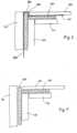
- FIG. 6 shows the use of at least one joint sealing tape 360, which is arranged between a strut 120 and/or 143 and the layer 300.
- the joint sealing tape 360 is preferably glued to at least the strut 120 and/or 143 and/or the layer 300.
- An outer wall 160 and/or 163 is in front of the layer.
- a joint sealing tape 360 is attached between the strut 120 and/or 143 and the outer wall 160 and/or 163.
- the joint sealing strip advantageously has an adhesive layer on one side and a sliding layer or at least one layer with a reduced friction factor on the second side, so that the outer wall 160 and/or 163 can be hung on the strut 120 and/or 143.
- the joint sealing tape is advantageously used at least on a number of several struts 120, 121, 122, 123, 130, 131, 132, 133, 140, 141, 142 and/or 143 or even completely opposite several or all outer walls 160 , 161, 162, 163 or 164 are used.
- FIG 8 shows the basic structure when using a shrink hood that is placed over the air/water heat pump 100.
- the shrink hood contracts and encloses the air/water heat pump in an airtight manner.
- the outer walls 160, 161, 162, 163, 164 are attached to the air/water heat pump, in particular hooked into place.
- the outer wall 160 has an inner air duct, not shown in detail, for supply air and exhaust gas with corresponding openings 180, 181. With the air/water heat pump and a ventilation unit, the exhaust gas is air.
- the outer wall 160 thus forms not just a simple wall but a functional part with an inner air duct.
Landscapes
- Engineering & Computer Science (AREA)
- Chemical & Material Sciences (AREA)
- Combustion & Propulsion (AREA)
- Mechanical Engineering (AREA)
- General Engineering & Computer Science (AREA)
- Housings, Intake/Discharge, And Installation Of Fluid Heaters (AREA)
- Building Environments (AREA)
- Other Air-Conditioning Systems (AREA)
Description
- Die Erfindung betrifft eine Luft/Wasser-Wärmepumpe für die Aufstellung in einem Gebäude, in dem ein zumindest teilweise durch eine Wand gebildeter Luftweg von einer Luftansaugöffnung zu einer Fortgasöffnung führt, mit einem im Luftweg befindlichen Raum, in dem ein Ventilator angeordnet ist, der Gas zu einem Wärmetauscher fördert.
- Außenluft-führende Haustechnikgeräte, insbesondere Luft/Wasser-Wärmepumpen zur Beheizung von Wohngebäuden, werden als Geräte zur Außen- und zur Innenaufstellung angeboten. Moderne Gebäude werden möglichst luftdicht ausgeführt, mit einer durch Undichtigkeiten in der Gebäudehülle bedingten Luftwechselrate. Im Bereich von Undichtigkeiten des Gehäuses des Außenluft-führenden Haustechnikgeräts kann es zu Kondensat- oder Eisbildung kommen. Beides kann Feuchtigkeitsschäden hervorrufen. Luft/Wasser-Wärmepumpen weisen zur Verhinderung von Feuchtigkeitsschäden eine Abtauwanne insbesondere im Bereich des Verdampfers auf, in der Feuchtigkeit gesammelt werden kann.
- Gemäß
EP 1 870 643 A2 ist eine Heizvorrichtung mit einer ersten und einer zweiten Wärmepumpe bekannt. Wahlweise wird die erste oder die zweite Wärmepumpe angesteuert. Die erste und zweite Wärmepumpe sind vorzugsweise in einem nach außen abgeschlossenen, wärmegedämmten Gehäuse angeordnet, das vorzugsweise luftdicht ist. Durch verschiedene Bereiche strömt Luft durch einen Wärmetauscher und einen Verdampfer sowie Kondensatoren. Diese Bereiche sind vorzugsweise zueinander isoliert, und nur über den Wärmetauscher sind die Kondensatoren und der Verdampfer miteinander verbunden. - Bei einer Wärmepumpe 100 gemäß
DE 20 2008 000 950 U1 sind diejenigen Komponenten, an welchen im Betrieb der Wärmepumpe Wasser kondensieren kann, zumindest teilweise thermisch isoliert. Zumindest stehen die aneinandergrenzenden Wärmedämmungen in so engem Kontakt, dass diese luftdicht aufeinanderstoßen. - Die
DE 297 12 751 U1 betrifft eine Rahmenkonstruktion für eine Kammer vorzugsweise eine Ansaugkammer (6) einer Klimaanlage, wobei sich ein Temperaturgradient zwischen der Umgebungstemperatur (T0) und der Kammertemperatur (T1) einstellt, mit einem Tragrahmen (26) mit einem Kern (28), der mit einem Mantel (30) umgeben ist, dessen Wärmeleitfähigkeit größer ist als die diejenige des Kerns (28), dadurch gekennzeichnet, daß zumindest in in den späteren Trennfugen (16) zwischen Tragrahmen (26) und einer Beplankung (14') liegenden Innenstirnflächen (36, 38) Schichten (46a) aus einem thermisch schlecht leitenden Material münden. - Dokument
EP 0 066 364 A1 offenbart eine Luft/Wasser Wärmepumpe mit den Merkmalen des Oberbegriffs von Anspruch 1. - Aufgabe der Erfindung ist es, eine Luft/Wasser-Wärmepumpe, für eine Aufstellung in einem Gebäude bereitzustellen, welches dazu beiträgt, Energieverluste und Feuchtigkeitsschäden insbesondere des Gebäudes zu verhindern, wobei eine einfache, preiswerte, zuverlässige und für die Fertigung prozesssichere Herstellung des Außenluft-führenden Haustechnikgeräts möglich ist.
- Gelöst ist die Aufgabe durch die Merkmale des Anspruchs 1.
- Ein Brennstoffzellenheizgerät (BZH) bzw. ein Lüftungsgerät fallen nicht unter den Schutzbereich der Ansprüche.
- Ein in einem Gebäude aufgestelltes Außenluft-führendes Haustechnikgerät, nämlich eine Wärmepumpe, ein Lüftungsgerät oder ein Brennstoffzellenheizgerät (BZH) ist dazu insbesondere im Bereich des Luftweges, vorzugsweise auf einer Ansaugseite oder einer Ausblasseite gegenüber dem Aufstellraum mit einer Schicht, insbesondere einer Folie abgedichtet. Im Luftweg ist ein erster Wärmeaustauscher, insbesondere im Heizbetrieb einer Luft/Wasser-Wärmepumpe ein Kältemittelverdampfer, und im Kühlbetrieb ein Kältemittelverflüssiger, bei einem BZH ein Brennstoffzellenstack und Wärmetauscher, oder bei einem Lüftungsgerät ein Luft/Luft-Wärmetauscher angeordnet. Der Luftweg bei einer Luft/Wasser-Wärmepumpe weist vorteilhaft eine Wand auf. Die Wand kann in vorteilhafter Weise auch die Wand eines Rohres oder eines anderen Luftkanals sein. Bei einer vorteilhaften Luft/Wasser-Wärmepumpe, bei einem BZH oder einem Lüftungsgerät ist der Luftweg vorteilhaft zumindest teilweise durch Luft- oder Gaskanäle oder Rohre gebildet. Auch flexible Rohre aus Kunststoff oder Metall stellen vorteilhaft zumindest einen Teil des Luftweges dar. Vorteilhaft ist zumindest eine Abdichtung mit dünnen Schichten um den ersten Wärmeaustauscher herum oder wenigstens auf einer Seite des Ventilators um einen Ventilator. Im Ausführungsbeispiel ist eine Luft/Wasser-Wärmepumpe beschrieben, die Abdichtung erfolgt in gleicher Weise bei einem BZH oder bei einem Lüftungsgerät. Bei luftdicht ausgeführten Gebäuden ist die Luftdichtigkeit der Gebäudehülle durch das innen aufgestellte Außenluft-führende Haustechnikgerät somit aufrecht erhalten. Undichtigkeiten des Gehäuses des Außenluft-führenden Haustechnikgeräts sind weitgehend vermieden, und eine Kondensat- oder Eisbildung kann nicht auftreten. Somit treten insbesondere Feuchtigkeitsschäden im Aufstellraum nicht auf. Es ist vorteilhaft, noch weitere Teile des Außenluft-führenden Haustechnikgeräts luftdicht auszuführen, die sich im Bereich des Unterdrucks, dies ist der Bereich des Luftweges in Strömungsrichtung des Gases (insbesondere Luft) vor dem Ventilator, oder des Überdrucks, dies ist der Bereich des Luftweges in Strömungsrichtung des Gases (insbesondere Luft oder Abgas) hinter dem Ventilator, befinden. Bei einer Luft/Wasser-Wärmepumpe ist somit eine Schicht um die Verdampfer-Ansaugseite oder im Bereich des Überdrucks auf der Ausblasseite angebracht.
- Ein weiterer Vorteil der Erfindung besteht darin, dass bei Bedarf die gesamte Luft/Wasser-Wärmepumpe ohne die Verkleidungsteile, und nicht nur der Luftweg abgeklebt wird, um die Dichtigkeit zu verbessern. Diese Ausführung ist später näher beschrieben. Dabei ist die Luftansaugöffnung und die Fortgasöffnung nicht von der Folie verschlossen.
- Es ist vorteilhaft noch weitere Teile der Luft/Wasser-Wärmepumpe luftdicht auszuführen, die sich insbesondere im Bereich des Unterdrucks oder des Überdrucks befinden. Bei der Luft/Wasser-Wärmepumpe erfolgt dies auf der Verdampfer-Ansaugseite und/oder im Bereich des Überdrucks auf der Ausblasseite. Ein weiterer Vorteil der Erfindung besteht darin, dass bei Bedarf die gesamte Luft/Wasser-Wärmepumpe, und nicht nur der Luftweg, abgeklebt ist, um die Dichtigkeit zu verbessern. Dabei ist die Luftansaugöffnung und die Fortgasöffnung nicht von der Folie verschlossen.
- Eine vorteilhaft ausgestaltete Luft/Wasser-Wärmepumpe wird mittels unterschiedlicher Verkleidungsteile einmal zur innen und einmal zur außen aufgestellten Wärmepumpe komplettiert. Ein Abkleben erfolgt zumindest für Geräte, die für die Innenaufstellung vorgesehen sind. Dennoch kann die Gestell- oder Gehäusekonstruktion für die beiden Varianten nahezu die gleiche sein.
- Gemäß der Erfindung ist eine Luft/Wasser-Wärmepumpe für die Aufstellung in einem Gebäude, mit wenigstens teilweise zusätzlich zu einem Verkleidungsteil wie einer Außenwand angebrachten dünnen, flexiblen und weitgehend luftdichten, folienartigen Schicht ausgerüstet, wodurch die Luft/Wasser-Wärmepumpe weitgehend luftdicht zum Gebäude ist. Die Schicht ist vorzugsweise weniger als ca. 3 mm, weiterhin besonders vorteilhaft weniger als 1 mm, insbesondere ca. 0,1 mm dick. In der Luft/Wasser-Wärmepumpe ist ein Luftweg gebildet, der von einer Luftansaugöffnung zu einer Fortgasöffnung führt, wobei sich im Luftweg ein Raum für einen Ventilator befindet, der die Luft durch die Luftansaugöffnung führt. Bei einer Luft/Wasser-Wärmepumpe handelt es sich beim Gas weiterhin um Außenluft, die zu wenigstens einem ersten Wärmetauscher und durch die Fortgasöffnung aus der Wärmepumpe heraus gefördert wird.
- Bei einem BZH, das nicht unter den Schutzbereich der Ansprüche fällt, erfolgt das Ansaugen der Außenluft ebenfalls über einen Luftweg, der von einer Luftansaugöffnung und einem Ansaugraum, in dem einen Ventilator sitzt, gebildet ist. Zur Luft wird nun in vorteilhafter Weise ein Brennstoff, insbesondere ein Brenngas hinzugemischt, vorzugsweise in einer Kammer, bei einer unterstöchiometrischen Reaktion reformiert und einem hoch wärmegedämmten Brennstoffzellenstack zugeführt, in dem Strom erzeugt wird. In vorteilhafter Weise erfolgt nach dem Durchströmen des Brennstoffzellenstacks eine Nachverbrennung und vorteilhaft ein Wärmeaustausch in einem ersten Wärmetauscher des BZH, wo die Wärme des Brenngases auf eine Wärmeträgerflüssigkeit übertragen wird. Es wird nun als Gas ein Abgas zur Fortgasöffnung gefördert.
- Bei einem Lüftungsgerät, das nicht unter den Schutzbereich der Ansprüche fällt, handelt es sich bei dem ersten Wärmetauscher insbesondere um einen Luft/Luft-Wärmeaustauscher. Das hier behandelte Gas ist Luft.
- Gemäß der Erfindung ist die Schicht der Luft/Wasser-Wärmepumpe zwischen einer Außenwand und einer Oberfläche der Luft/Wasser-Wärmepumpe an Streben angeordnet, wobei die Schicht zumindest weitgehend luftdicht an den Streben anliegt.
- Gemäß der Erfindung ist die Schicht an wenigstens einer Oberfläche der Streben der Luft/Wasser-Wärmepumpe angeklebt.
- In einem vorteilhaften Ausführungsbeispiel ist die Schicht zwischen der wenigstens einen Außenwand und einer Oberfläche um die Luft/Wasser-Wärmepumpe herumgewickelt, insbesondere um die Streben.
- Vorteilhaft ist es weiterhin, wenn die Schicht Ausstanzungen oder Ausschnitte aufweist, durch die Gestellteile, Funktionsteile, Anschlussleitungen, Verbindungselemente oder Anschlusskabel durch die Schicht hindurchtreten können.
- Eine Luft/Wasser-Wärmepumpe ist vorteilhafterweise so ausgestaltet, dass die folienartige Schicht eine Folie aus Kunststoff oder Metall, Teerpappe, imprägniertem Papier, imprägniertem Stoff, Schaumstoffvlies, Gummi oder ähnlichem flexiblen, luftdichten Material mit einer Dicke von weniger als ca. 3 mm, ca. 1 mm oder insbesondere ca. 0,1 mm ist, insbesondere PE oder PET-Folie.
- Gemäß einem Gedanken der Erfindung ist die Schicht aus einer Kunststoff-Schrumpffolie, insbesondere einer Schrumpfhaube gebildet, so dass sich eventuelle Falten oder Übermaße durch Erwärmung beseitigen lassen.
- Bei einer Luft/Wasser-Wärmepumpe ist die Schicht teilweise im Bereich von Klebestellen einseitig mit Klebstoff vorbeschichtet, zwischen der Schicht und vorzugsweise einer Strebe ist ein doppelseitiges Klebeband angeklebt oder ein elastisches Fugendichtungsband an der Strebe oder der Schicht angeklebt.
- Weiterhin hat es sich als vorteilhaft erwiesen, wenn die Luft/Wasser-Wärmepumpe von der Schicht vollständig oder nahezu vollständig umschlossen ist.
- Bei einer Luft/Wasser-Wärmepumpe ist es insbesondere vorteilhaft, dass der Luftweg, bestehend aus dem Raum, dem Luftanschluss, dem Ventilator, einem erstem Wärmeaustauscher vorzugsweise mit einer Abtauwanne, und dem Ausblasraum mit dem Luftanschluss vollständig von einer Schicht umgeben ist.
- Gemäß einem weiteren vorteilhaften Gedanken der Erfindung ist auf wenigstens einer Strebe ein elastisches Fugendichtungsband so angebracht, insbesondere angeklebt, dass es an einer Außenwand anliegt.
- Überraschenderweise wurde gefunden, dass die Bauweise für eine Luft/Wasser-Wärmepumpe auch für ein Raumluft-unabhängig arbeitendes Brennstoff-Zellen-Heizgerät (BZH) geeignet ist, um eine entsprechende Gasdichtigkeit herzustellen. Brennstoffzellenheizgeräte, welche nicht unter den Schutzbereich der Ansprüche fallen, weisen ebenfalls einen Luftweg auf, durch den Außenluft, oder zumindest vom Ausstellungsraum des BHZ unabhängige Luft zugeführt wird. Weiterhin wird ein Gasstrom, beim Brennstoffzellenheizgerät ist es ein Abgasstrom, aus dem Gerät nach außen geführt. In vorteilhafter Weise weist das Brennstoffzellenheizgerät einen Rahmen aus Streben auf, welche mit einer Folie beklebt sind, und Außenwände, die vor die Folien bzw. Streben gesetzt sind. Hierdurch ist eine entsprechende Gasdichtigkeit zwischen einem Innenraum des Brennstoffzellenheizgerätes und dem das Brennstoffzellenheizgerät umgebenden Raum erreicht.
- In den Figuren ist ein entsprechendes Ausführungsbeispiel gezeigt:
- Figur 1 :
- Luft/Wasser-Wärmepumpe mit Schicht,
- Figur 2 :
- Luft/Wasser-Wärmepumpe mit Schicht,
- Figur 3 :
- Luft/Wasser-Wärmepumpe mit Schicht,
- Figur 4 :
- Schicht mit Ausstanzungen,
- Figur 5 :
- Schicht mit Ausstanzungen und Verklebung,
- Figur 6 :
- Teilansicht der Abdichtung mit Fugendichtungsband,
- Figur 7 :
- Teilansicht der Abdichtung mit Fugendichtungsband,
- Figur 8 :
- Wärmepumpe mit einer Schrumpfhaube.
- Gemäß
Fig. 1 ist eine Luft/Wasser-Wärmepumpe 100 mit Streben 120, 121, 122, 123, 130, 131, 132, 133, 140, 141, 142, und/oder 143 gezeigt. Die Luft/Wasser-Wärmepumpe 100 weist einen inneren Luftweg 200 auf. Der Luftweg beginnt insbesondere mit einer Luftansaugöffnung 210, an die sich wenigstens eine Wand 201 anschließt. In einem Raum 220 ist ein Ventilator 221 angeordnet, im Ausführungsbeispiel ist dieser Ventilator 221 an eine Tragwand 222 befestigt. Der Ventilator 221 ist vor einer Ventilatordüse 223 angeordnet, wodurch Luft in einen Ausblasraum 230 mit einer Fortgasöffnung 240 geblasen wird. Dieser Ausblasraum 230 hat einen Luftanschluss 241. - Die wenigstens eine Strebe 120, 121, 122, 123, 130, 131, 132, 133, 140, 141, 142, und/oder 143 bildet zumindest teilweise einen Rahmen der Luft/Wasser-Wärmepumpe 100. Auf die wenigstens eine Strebe 120, 121, 122, 123, 130, 131, 132, 133, 140, 141, 142, und/oder 143 ist wenigstens eine Schicht 300 mit Ausstanzungen 301, 302, 303, 304 sowie in vorteilhafter Weise mit Bohrungen 305 aufgebracht. Im gezeigten Ausführungsbeispiel gemäß
Fig.1 ist je eine Schicht 300, 310, 320, 330 an einer Vorderseite 101, einer Rückseite 102, einer rechten Seite 103 sowie einer linken Seite 104 angebracht. Vorteilhaft ist auch im Boden 105 sowie auf einem Oberteil 110 eine entsprechende Schicht aufgebracht. Die Schicht ist im Oberteil teilweise offen für den Außenluftstrom. Im Ausführungsbeispiel ist der Boden 105 sowie das Oberteil 110 durch andere Maßnahmen abgedichtet, wie z. B. druck-elastischer Kautschuk oder ähnliche Kunststoffmaterialien. Im Deckel 110 und/oder im Boden 105 werden insbesondere Fugendichtungsmaterialien, insbesondere Fugendichtungsbänder, verwendet, Fugen und Öffnungen mit Klebebändern abgeklebt oder mit Silikon oder ähnlichen Spritz-Materialien abgedichtet. Vorteilhaft ist die Verwendung von umschäumten Profilen, so dass die Streben bereits von Schaumstoff oder einem ähnlichen Material umgeben sind. - Ausstanzungen und/oder Bohrungen dienen dazu, um Halteeinrichtungen 170, wie Haken, Schrauben, Niete o.ä., die insbesondere an den Streben ausgebildet sind oder daran befestigt werden, durch die Schicht hindurchzuführen. An die Haltevorrichtungen 170 werden die Verkleidungsteile wie hier im Ausführungsbeispiel die Außenwände 160 161 162 163 164 eingehakt, verschraubt oder anderweitig befestigt. Beim Einhaken entstehen insbesondere Druck- und Scherkräfte zwischen den Außenwänden und der Schicht. Daher ist es vorteilhaft, eine Schicht zu verwenden, die zur Außenwand hin einen möglichst geringen Reibfaktor hat. Besonders vorteilhaft ist es, wenn auf der Schicht noch eine Gleitschicht, insbesondere Teflonschicht aufgebracht ist, die besonders glatt ist, so dass beim Einhaken und Hineinrutschen in die Befestigungshaken kaum Scherkräfte entstehen.
- Der Luftweg 200 ist an die Außenluft angeschlossen, einmal durch die Luftansaugöffnung 210 und einmal durch die Fortgasöffnung 240. Im Betrieb der Wärmepumpe entsteht in Strömungsrichtung vor dem Ventilator 221 ein Unterdruck und im Ausblasraum 230 ein Überdruck. Insbesondere durch die unterschiedlichen Druckverhältnisse zwischen dem Inneren des Gebäudes und dem Unterdruck bzw. dem Überdruck in der Wärmepumpe wird durch die an die Streben angeklebten Schichten ein Luftaustausch zwischen Außenluft und Innenluft vermieden. Aber auch, wenn die Wärmepumpe nicht im Betrieb ist, d.h. z.B. dass der Ventilator 221 steht, können z.B. durch Winddruck Druck-Unterschiede zwischen dem Inneren des Gebäudes und der Außenluft bestehen. Durch die Gasabdichtung mit den Schichten ist ein Luftaustausch auch in diesem Falle zwischen Außenluft und Innenluft vermieden.
- Der im Luftweg 200 angeordnete erste Wärmeaustauscher 410 ist im Heizbetrieb ein Verdampfer. Bei Luft/Wasser-Wärmepumpen 100, die auch kühlen können, ist der erste Wärmetauscher 410 im Kühlbetrieb ein Verflüssiger. Die erste Wärmetauscher 410 ist in einen Kältemittelkreislauf 400 eingebunden, der weiterhin einen Verdichter 430, Kältemittelleitungen 450, Filtertrockner 440, ein Expansionsventil 420, sowie einen zweiten Wärmetauscher 460 aufweist. Im Heizbetrieb ist der zweite Wärmeaustauscher 460 ein Verflüssiger und im Kühlbetrieb der Luft/Wasser-Wärmepumpe 100 ein Verdampfer. Weiterhin weist die Luft/Wasser-Wärmepumpe 100 einen Schaltraum 500 auf.
- Im Ausführungsbeispiel bestehen die Schichten 300, 310, 320, 330, die mit einer schrägen Strich-Punkt-Linie dargestellt sind, aus einer transparenten PET-Folie (daher in den Figuren teilweise mit einer Strich-Kurzstrich-Linie dargestellt) mit einer Dicke von weniger als 3 mm, insbesondere ca. 0,1 mm. Dies hat den Vorteil, dass die Luft/Wasser-Wärmepumpe 100 bei Abnahme einer oder mehrerer Außenwände 160, 161, 162,163 einzusehen ist, insbesondere der Kältemittelkreislauf 400 sowie die Luftweg 200 sind zumindest zum Teil einzusehen.
- In
Fig. 4 ist eine Schicht 300, insbesondere aus einer transparenten PET-Folie mit einer Dicke von weniger als 3 mm, ca. 1 mm oder insbesondere 0,1 mm mit Ausstanzungen sowie Bohrungen 305 gezeigt. Weiterhin sind zwei Öffnungen 306, 307 angebracht, durch die insbesondere Anschlussleitungen der Hydraulik sowie für die Stromversorgung oder andere Leitungen durchgeführt sind. -
Fig. 5 zeigt ebenfalls eine Schicht 300 mit Ausstanzungen 301 und Bohrungen 305 sowie zusätzlich mit einer bereits aufgebrachten Klebschicht 150, insbesondere beispielsweise ein doppelseitiges Klebeband, oder mit einer Klebefolie. -
Fig. 6 zeigt die Verwendung wenigstens eines Fugendichtungsbands 360, welches zwischen einer Strebe 120 und/oder 143 und der Schicht 300 angeordnet ist. Das Fugendichtungsband 360 ist vorzugsweise zumindest an der Strebe120 und/oder 143 und/oder der Schicht 300 angeklebt. Eine Außenwand 160 und/oder 163 befindet sich vor der Schicht. - In einem weiteren Ausführungsbeispiel gemäß
Fig. 7 ist ein Fugendichtungsband 360 zwischen der Strebe 120 und/oder 143 und der Außenwand 160 und/oder 163 angebracht. In vorteilhafter Weise weist das Fugendichtungsband auf einer Seite eine Klebschicht und auf einer zweiten Seite eine Gleitschicht oder zumindest eine Schicht mit einem verminderten Reibfaktor auf, damit die Außenwand 160 und/oder 163 an die Strebe 120 und/oder 143 eingehängt werden kann. Die Verwendung des Fugendichtungsbandes wird in vorteilhafter Weise zumindest an einer Anzahl von mehreren Streben 120, 121, 122, 123, 130, 131, 132, 133, 140, 141, 142, und/oder 143 oder auch komplett gegenüber mehreren oder allen Außenwänden 160, 161, 162, 163 oder 164 verwendet. -
Fig. 8 zeigt den prinzipiellen Aufbau bei Verwendung einer Schrumpfhaube, die über die Luft/Wasser-Wärmepumpe 100 gebracht wird. Durch Erhitzen zieht sich die Schrumpfhaube zusammen und umschließt die Luft/Wasser-Wärmepumpe luftdicht. - Die Außenwände 160, 161, 162, 163, 164 werden dann, wenn die Schrumpfhaube über die Wärmepumpe gebracht ist, an der Luft/Wasser-Wärmepumpe befestigt, insbesondere eingehakt. Die Außenwand 160 weist eine innere nicht weiter dargestellte Luftführung für Zuluft und Fortgas mit entsprechenden Öffnungen 180, 181 auf. Bei der Luft/Wasser-Wärmepumpe und einem Lüftungsgerät ist das Fortgas Luft. Die Außenwand 160 bildet somit nicht nur eine einfache Wand sondern einen Funktionsteil mit einer inneren Luftführung.
Claims (10)
- Luft/Wasser-Wärmepumpe (100) für die Aufstellung in einem Gebäude, in der ein zumindest teilweise durch eine Wand (201) gebildeter Luftweg (200) von einer Luftansaugöffnung (210) zu einer Fortgasöffnung (240) führt, miteiner Vorderseite (101), einer Rückseite (102), einer rechten Seite (103) sowie einer linken Seite (104), die jeweils eine Außenwand (161, 162, 163, 164) aufweisen,einem Boden (105) und einem Oberteil (110),einem im Luftweg (200) befindlichen Raum (220), in dem ein Ventilator (221) angeordnet ist, der Luft zu einem Wärmetauscher fördert,gekennzeichnet durch dünne, flexible und luftdichte, folienartige Schichten (300) und Streben, die einen Rahmen der Luft/Wasser-Wärmepumpe bilden,wobei die Schichten (300) zwischen den Außenwänden (161, 162, 163, 164) und den Oberflächen der Streben angeordnet sind und die Schichten (300) weitgehend luftdicht an den Oberflächen anliegen , wodurch die Luft/Wasserwärmepumpe (100) weitgehend luftdicht zum Gebäude ist.
- Luft/Wasser-Wärmepumpe (100) nach Anspruch 1,
dadurch gekennzeichnet,
dass die Schichten (300) an der Oberfläche der Streben angeklebt sind. - Luft/Wasser-Wärmepumpe (100) nach einem der vorhergehenden Ansprüche,
dadurch gekennzeichnet,
dass die Schichten (300) um die Streben (120, 121) der Wärmepumpe herumgewickelt sind. - Luft/Wasser-Wärmepumpe (100) nach einem der vorhergehenden Ansprüche,
dadurch gekennzeichnet,
dass die Schichten (300) wenigstens eine Ausstanzung (301, 302, 303, 304) oder Ausschnitte aufweisen, durch die Gestellteile, Funktionsteile, Anschlussleitungen, Verbindungselemente oder Anschlusskabel durch die Schichten (300) hindurchtreten. - Luft/Wasser-Wärmepumpe (100) nach einem der vorhergehenden Ansprüche, dadurch gekennzeichnet,
dass die Schichten (300) eine Folie aus Kunststoff oder Metall, Teerpappe, imprägniertem Papier, imprägniertem Stoff, Schaumstoffvlies, Gummi oder ähnlichem flexiblen luftdichten Material, mit einer Dicke von weniger als ca. 3 mm, ca. 1 mm oder insbesondere ca. 0,1 mm sind und insbesondere aus PE oder PET-Folie bestehen. - Luft/Wasser-Wärmepumpe (100) nach einem der vorhergehenden Ansprüche,
dadurch gekennzeichnet,
dass die Schichten (300, 310, 320, 330) aus einer Kunststoff-Schrumpffolie, insbesondere einer Schrumpfhaube (340) gebildet sind, so dass sich eventuelle Falten oder Übermaße durch Erwärmung beseitigen lassen. - Luft/Wasser-Wärmepumpe (100) nach einem der vorhergehenden Ansprüche,
dadurch gekennzeichnet,
dass die Schichten (300) im Bereich von Klebestellen einseitig mit Klebstoff vorbeschichtet sind, zwischen der Schicht und der Oberfläche der Strebe ein doppelseitiges Klebeband angeklebt ist oder ein elastisches Fugendichtungsband (360) an der Strebe (120) oder der Schicht (300) angeklebt ist. - Luft/Wasser-Wärmepumpe (100) nach einem der vorhergehenden Ansprüche,
dadurch gekennzeichnet,
dass die Wärmepumpe (100) von den Schichten (300) nahezu vollständig, insbesondere bis auf den Boden (105), oder vollständig umschlossen ist und die Luftansaugöffnung (210) und die Fortgasöffnung (240) frei sind. - Luft/Wasser-Wärmepumpe (100) nach einem der vorhergehenden Ansprüche,
dadurch gekennzeichnet,
dass der Luftweg (200), bestehend aus dem Raum (220), einem erstem Wärmeaustauscher (410) mit einer Abtauwanne (190) und dem Ventilator (221), vollständig von einer Schicht (300) umgeben ist, wobei die Luftansaugöffnung (210) und die Fortgasöffnung (240) offen zur Außenluft sind. - Luft/Wasser-Wärmepumpe (100) nach einem der vorhergehenden Ansprüche, dadurch gekennzeichnet,
dass auf wenigstens einer Strebe ein elastisches Fugendichtungsband (360) mit einer Klebschicht und einer Oberfläche mit einem verminderten Reibwert angebracht ist, an dem eine Außenwand anliegt.
Applications Claiming Priority (1)
| Application Number | Priority Date | Filing Date | Title |
|---|---|---|---|
| DE102009057481A DE102009057481A1 (de) | 2009-12-10 | 2009-12-10 | Außenluft-führendes Haustechnikgerät |
Publications (3)
| Publication Number | Publication Date |
|---|---|
| EP2345856A2 EP2345856A2 (de) | 2011-07-20 |
| EP2345856A3 EP2345856A3 (de) | 2017-01-25 |
| EP2345856B1 true EP2345856B1 (de) | 2023-08-02 |
Family
ID=43943041
Family Applications (1)
| Application Number | Title | Priority Date | Filing Date |
|---|---|---|---|
| EP10015513.4A Active EP2345856B1 (de) | 2009-12-10 | 2010-12-10 | Luft/Wasser-Wärmepumpe |
Country Status (3)
| Country | Link |
|---|---|
| EP (1) | EP2345856B1 (de) |
| DE (1) | DE102009057481A1 (de) |
| PL (1) | PL2345856T3 (de) |
Families Citing this family (4)
| Publication number | Priority date | Publication date | Assignee | Title |
|---|---|---|---|---|
| EP2719967B1 (de) * | 2012-10-09 | 2019-02-06 | Roth Werke GmbH | Verfahren zur Temperierung eines Gebäudes |
| DE102018129519A1 (de) * | 2018-11-23 | 2020-05-28 | Vaillant Gmbh | Verstärktes Wärmepumpengehäuse |
| DE102020100806A1 (de) * | 2019-03-08 | 2020-09-10 | Stiebel Eltron Gmbh & Co. Kg | Luft-Wasser-Wärmepumpe und zugehöriges Verfahren |
| DE102019001719A1 (de) * | 2019-03-13 | 2020-09-17 | Stiebel Eltron Gmbh & Co. Kg | Haustechnikgerrät und luftdichte Kabeldurchführung |
Citations (1)
| Publication number | Priority date | Publication date | Assignee | Title |
|---|---|---|---|---|
| DE10326912A1 (de) * | 2002-06-17 | 2003-12-24 | Martin Raes | Blockheizkraftwerk |
Family Cites Families (8)
| Publication number | Priority date | Publication date | Assignee | Title |
|---|---|---|---|---|
| US4426120A (en) * | 1981-04-20 | 1984-01-17 | Mcquay Inc. | Sectioned cabinet for room air conditioning unit |
| DE3118053C2 (de) * | 1981-05-07 | 1985-03-14 | Günter Dipl.-Architekt 6096 Raunheim Hack | Plattenförmiges wärmedämmendes Bauelement für Fensterbrüstungen von Gebäuden |
| US5125197A (en) * | 1991-05-21 | 1992-06-30 | Fuchs Arthur E | Interior cover for an air conditioner mounted in a wall |
| DE29712751U1 (de) * | 1997-07-18 | 1997-10-02 | Heber GmbH, 94094 Rotthalmünster | Rahmenkonstruktion |
| DE102005032251A1 (de) * | 2005-07-09 | 2007-01-18 | Deere & Company, Moline | Gehäuse einer Klimaanlage |
| DE202006009538U1 (de) * | 2006-06-19 | 2006-10-12 | Schwörer Haus KG | Wärmepumpenanordnung |
| DE202008000950U1 (de) | 2008-01-22 | 2008-04-03 | Alpha-Innotec Gmbh | Wärmepumpe |
| DE102008051032A1 (de) * | 2008-10-13 | 2010-04-15 | Pluggit International B.V. | Modulares und Fassaden-integriertes Lüftungs- und Klimasystem |
-
2009
- 2009-12-10 DE DE102009057481A patent/DE102009057481A1/de active Pending
-
2010
- 2010-12-10 EP EP10015513.4A patent/EP2345856B1/de active Active
- 2010-12-10 PL PL10015513.4T patent/PL2345856T3/pl unknown
Patent Citations (1)
| Publication number | Priority date | Publication date | Assignee | Title |
|---|---|---|---|---|
| DE10326912A1 (de) * | 2002-06-17 | 2003-12-24 | Martin Raes | Blockheizkraftwerk |
Also Published As
| Publication number | Publication date |
|---|---|
| DE102009057481A1 (de) | 2011-06-16 |
| PL2345856T3 (pl) | 2024-02-05 |
| EP2345856A2 (de) | 2011-07-20 |
| EP2345856A3 (de) | 2017-01-25 |
Similar Documents
| Publication | Publication Date | Title |
|---|---|---|
| EP3669127B1 (de) | Wärmetauscherelement und verfahren zu dessen herstellung | |
| DE112009001246T5 (de) | Neuerung für isolierende Dämmplatten mit Wärmeaustausch und Lüftungskanälen | |
| DE1270260B (de) | Vorrichtung zum Beheizen und Kuehlen von Raeumen | |
| EP1907762B1 (de) | Luftkühl- und luftentfeuchtungsmodul aus kapillarrohrmatten und verfahren zu seiner anwendung | |
| DE202009003205U1 (de) | Plattenelement für ein Deckenheizungs- und/oder Kühlungselement | |
| DE4132870A1 (de) | Wandheizkoerper | |
| EP2345856A2 (de) | Außenluft-führendes Haustechnikgerät | |
| DE60113668T2 (de) | Belüftungsventil für kältegeräte | |
| DE102014007735A1 (de) | Lüftungsanlage | |
| DE102020100806A1 (de) | Luft-Wasser-Wärmepumpe und zugehöriges Verfahren | |
| DE19925823C2 (de) | Vorrichtung zur Wärmerückgewinnung bei der Belüftung und Heizung von Wohn- und Nutzräumen | |
| EP1837610A2 (de) | Raumlüftungsvorrichtung mit Wärmerückgewinnung aus Abluft | |
| WO2023222539A1 (de) | Wärmetauscherpaneel zur temperierung eines raumes | |
| EP0951630B1 (de) | Raumbelüftungsverfahren und vorrichtung zur durchführung des verfahrens | |
| EP2469208A2 (de) | Wärmeübertrager und Wärmepumpenkreis | |
| DE102013114085A1 (de) | Lüftungsgerät zur Raumlüftung | |
| EP1348911B1 (de) | Luftaufbereitungsgerät zur Regulierung der Wärme und der Luftfeuchtigkeit in geschlossenen Räumen | |
| DE19845557A1 (de) | Luftzirkulationsheizsystem in der Dämmerung mit Einbringung der Raumentlüftung und eine technische Anlage zum Betreiben mit Nutzung von Alternativ-, und Verlustenergien | |
| EP0027147A1 (de) | Wärmesammelanlage | |
| DE19803335A1 (de) | Lüftungsgerät für einen Gebäuderaum | |
| EP2792961B1 (de) | Wärmetauscheraggregat | |
| EP2746694A1 (de) | Thermoanordnung, Verfahren zum Herstellen einer Thermoanordnung und Verfahren zum Montieren einer Thermoanordnung | |
| DE102014226355A1 (de) | Lüftungsgerät | |
| DE102013102423A1 (de) | Verfahren und Vorrichtung zum Beheizen von Räumen mittels Strahlungsplatten | |
| DE202009013827U1 (de) | Niedrigenergie- oder Passivhaus mit Gasbrenner |
Legal Events
| Date | Code | Title | Description |
|---|---|---|---|
| PUAI | Public reference made under article 153(3) epc to a published international application that has entered the european phase |
Free format text: ORIGINAL CODE: 0009012 |
|
| AK | Designated contracting states |
Kind code of ref document: A2 Designated state(s): AL AT BE BG CH CY CZ DE DK EE ES FI FR GB GR HR HU IE IS IT LI LT LU LV MC MK MT NL NO PL PT RO RS SE SI SK SM TR |
|
| AX | Request for extension of the european patent |
Extension state: BA ME |
|
| PUAL | Search report despatched |
Free format text: ORIGINAL CODE: 0009013 |
|
| AK | Designated contracting states |
Kind code of ref document: A3 Designated state(s): AL AT BE BG CH CY CZ DE DK EE ES FI FR GB GR HR HU IE IS IT LI LT LU LV MC MK MT NL NO PL PT RO RS SE SI SK SM TR |
|
| AX | Request for extension of the european patent |
Extension state: BA ME |
|
| RIC1 | Information provided on ipc code assigned before grant |
Ipc: F24F 12/00 20060101AFI20161216BHEP Ipc: F24F 13/20 20060101ALI20161216BHEP Ipc: F25B 30/00 20060101ALI20161216BHEP |
|
| STAA | Information on the status of an ep patent application or granted ep patent |
Free format text: STATUS: REQUEST FOR EXAMINATION WAS MADE |
|
| 17P | Request for examination filed |
Effective date: 20170725 |
|
| RBV | Designated contracting states (corrected) |
Designated state(s): AL AT BE BG CH CY CZ DE DK EE ES FI FR GB GR HR HU IE IS IT LI LT LU LV MC MK MT NL NO PL PT RO RS SE SI SK SM TR |
|
| STAA | Information on the status of an ep patent application or granted ep patent |
Free format text: STATUS: EXAMINATION IS IN PROGRESS |
|
| 17Q | First examination report despatched |
Effective date: 20180913 |
|
| GRAP | Despatch of communication of intention to grant a patent |
Free format text: ORIGINAL CODE: EPIDOSNIGR1 |
|
| STAA | Information on the status of an ep patent application or granted ep patent |
Free format text: STATUS: GRANT OF PATENT IS INTENDED |
|
| INTG | Intention to grant announced |
Effective date: 20221011 |
|
| GRAJ | Information related to disapproval of communication of intention to grant by the applicant or resumption of examination proceedings by the epo deleted |
Free format text: ORIGINAL CODE: EPIDOSDIGR1 |
|
| STAA | Information on the status of an ep patent application or granted ep patent |
Free format text: STATUS: EXAMINATION IS IN PROGRESS |
|
| INTC | Intention to grant announced (deleted) | ||
| GRAP | Despatch of communication of intention to grant a patent |
Free format text: ORIGINAL CODE: EPIDOSNIGR1 |
|
| STAA | Information on the status of an ep patent application or granted ep patent |
Free format text: STATUS: GRANT OF PATENT IS INTENDED |
|
| INTG | Intention to grant announced |
Effective date: 20230322 |
|
| GRAS | Grant fee paid |
Free format text: ORIGINAL CODE: EPIDOSNIGR3 |
|
| GRAA | (expected) grant |
Free format text: ORIGINAL CODE: 0009210 |
|
| STAA | Information on the status of an ep patent application or granted ep patent |
Free format text: STATUS: THE PATENT HAS BEEN GRANTED |
|
| P01 | Opt-out of the competence of the unified patent court (upc) registered |
Effective date: 20230525 |
|
| AK | Designated contracting states |
Kind code of ref document: B1 Designated state(s): AL AT BE BG CH CY CZ DE DK EE ES FI FR GB GR HR HU IE IS IT LI LT LU LV MC MK MT NL NO PL PT RO RS SE SI SK SM TR |
|
| REG | Reference to a national code |
Ref country code: GB Ref legal event code: FG4D Free format text: NOT ENGLISH |
|
| REG | Reference to a national code |
Ref country code: CH Ref legal event code: EP |
|
| REG | Reference to a national code |
Ref country code: DE Ref legal event code: R096 Ref document number: 502010017055 Country of ref document: DE |
|
| REG | Reference to a national code |
Ref country code: IE Ref legal event code: FG4D Free format text: LANGUAGE OF EP DOCUMENT: GERMAN |
|
| REG | Reference to a national code |
Ref country code: LT Ref legal event code: MG9D |
|
| REG | Reference to a national code |
Ref country code: NL Ref legal event code: MP Effective date: 20230802 |
|
| REG | Reference to a national code |
Ref country code: SK Ref legal event code: T3 Ref document number: E 42520 Country of ref document: SK |
|
| PG25 | Lapsed in a contracting state [announced via postgrant information from national office to epo] |
Ref country code: GR Free format text: LAPSE BECAUSE OF FAILURE TO SUBMIT A TRANSLATION OF THE DESCRIPTION OR TO PAY THE FEE WITHIN THE PRESCRIBED TIME-LIMIT Effective date: 20231103 |
|
| PG25 | Lapsed in a contracting state [announced via postgrant information from national office to epo] |
Ref country code: IS Free format text: LAPSE BECAUSE OF FAILURE TO SUBMIT A TRANSLATION OF THE DESCRIPTION OR TO PAY THE FEE WITHIN THE PRESCRIBED TIME-LIMIT Effective date: 20231202 |
|
| PG25 | Lapsed in a contracting state [announced via postgrant information from national office to epo] |
Ref country code: SE Free format text: LAPSE BECAUSE OF FAILURE TO SUBMIT A TRANSLATION OF THE DESCRIPTION OR TO PAY THE FEE WITHIN THE PRESCRIBED TIME-LIMIT Effective date: 20230802 Ref country code: RS Free format text: LAPSE BECAUSE OF FAILURE TO SUBMIT A TRANSLATION OF THE DESCRIPTION OR TO PAY THE FEE WITHIN THE PRESCRIBED TIME-LIMIT Effective date: 20230802 Ref country code: PT Free format text: LAPSE BECAUSE OF FAILURE TO SUBMIT A TRANSLATION OF THE DESCRIPTION OR TO PAY THE FEE WITHIN THE PRESCRIBED TIME-LIMIT Effective date: 20231204 Ref country code: NO Free format text: LAPSE BECAUSE OF FAILURE TO SUBMIT A TRANSLATION OF THE DESCRIPTION OR TO PAY THE FEE WITHIN THE PRESCRIBED TIME-LIMIT Effective date: 20231102 Ref country code: NL Free format text: LAPSE BECAUSE OF FAILURE TO SUBMIT A TRANSLATION OF THE DESCRIPTION OR TO PAY THE FEE WITHIN THE PRESCRIBED TIME-LIMIT Effective date: 20230802 Ref country code: LV Free format text: LAPSE BECAUSE OF FAILURE TO SUBMIT A TRANSLATION OF THE DESCRIPTION OR TO PAY THE FEE WITHIN THE PRESCRIBED TIME-LIMIT Effective date: 20230802 Ref country code: LT Free format text: LAPSE BECAUSE OF FAILURE TO SUBMIT A TRANSLATION OF THE DESCRIPTION OR TO PAY THE FEE WITHIN THE PRESCRIBED TIME-LIMIT Effective date: 20230802 Ref country code: IS Free format text: LAPSE BECAUSE OF FAILURE TO SUBMIT A TRANSLATION OF THE DESCRIPTION OR TO PAY THE FEE WITHIN THE PRESCRIBED TIME-LIMIT Effective date: 20231202 Ref country code: HR Free format text: LAPSE BECAUSE OF FAILURE TO SUBMIT A TRANSLATION OF THE DESCRIPTION OR TO PAY THE FEE WITHIN THE PRESCRIBED TIME-LIMIT Effective date: 20230802 Ref country code: GR Free format text: LAPSE BECAUSE OF FAILURE TO SUBMIT A TRANSLATION OF THE DESCRIPTION OR TO PAY THE FEE WITHIN THE PRESCRIBED TIME-LIMIT Effective date: 20231103 Ref country code: FI Free format text: LAPSE BECAUSE OF FAILURE TO SUBMIT A TRANSLATION OF THE DESCRIPTION OR TO PAY THE FEE WITHIN THE PRESCRIBED TIME-LIMIT Effective date: 20230802 |
|
| PGFP | Annual fee paid to national office [announced via postgrant information from national office to epo] |
Ref country code: FR Payment date: 20231221 Year of fee payment: 14 Ref country code: DE Payment date: 20231214 Year of fee payment: 14 Ref country code: CZ Payment date: 20231204 Year of fee payment: 14 |
|
| PG25 | Lapsed in a contracting state [announced via postgrant information from national office to epo] |
Ref country code: ES Free format text: LAPSE BECAUSE OF FAILURE TO SUBMIT A TRANSLATION OF THE DESCRIPTION OR TO PAY THE FEE WITHIN THE PRESCRIBED TIME-LIMIT Effective date: 20230802 |
|
| PG25 | Lapsed in a contracting state [announced via postgrant information from national office to epo] |
Ref country code: SM Free format text: LAPSE BECAUSE OF FAILURE TO SUBMIT A TRANSLATION OF THE DESCRIPTION OR TO PAY THE FEE WITHIN THE PRESCRIBED TIME-LIMIT Effective date: 20230802 Ref country code: RO Free format text: LAPSE BECAUSE OF FAILURE TO SUBMIT A TRANSLATION OF THE DESCRIPTION OR TO PAY THE FEE WITHIN THE PRESCRIBED TIME-LIMIT Effective date: 20230802 Ref country code: ES Free format text: LAPSE BECAUSE OF FAILURE TO SUBMIT A TRANSLATION OF THE DESCRIPTION OR TO PAY THE FEE WITHIN THE PRESCRIBED TIME-LIMIT Effective date: 20230802 Ref country code: EE Free format text: LAPSE BECAUSE OF FAILURE TO SUBMIT A TRANSLATION OF THE DESCRIPTION OR TO PAY THE FEE WITHIN THE PRESCRIBED TIME-LIMIT Effective date: 20230802 Ref country code: DK Free format text: LAPSE BECAUSE OF FAILURE TO SUBMIT A TRANSLATION OF THE DESCRIPTION OR TO PAY THE FEE WITHIN THE PRESCRIBED TIME-LIMIT Effective date: 20230802 |
|
| PGFP | Annual fee paid to national office [announced via postgrant information from national office to epo] |
Ref country code: CH Payment date: 20240101 Year of fee payment: 14 |
|
| REG | Reference to a national code |
Ref country code: DE Ref legal event code: R097 Ref document number: 502010017055 Country of ref document: DE |
|
| PG25 | Lapsed in a contracting state [announced via postgrant information from national office to epo] |
Ref country code: IT Free format text: LAPSE BECAUSE OF FAILURE TO SUBMIT A TRANSLATION OF THE DESCRIPTION OR TO PAY THE FEE WITHIN THE PRESCRIBED TIME-LIMIT Effective date: 20230802 |
|
| PLBE | No opposition filed within time limit |
Free format text: ORIGINAL CODE: 0009261 |
|
| STAA | Information on the status of an ep patent application or granted ep patent |
Free format text: STATUS: NO OPPOSITION FILED WITHIN TIME LIMIT |
|
| 26N | No opposition filed |
Effective date: 20240503 |
|
| PG25 | Lapsed in a contracting state [announced via postgrant information from national office to epo] |
Ref country code: SI Free format text: LAPSE BECAUSE OF FAILURE TO SUBMIT A TRANSLATION OF THE DESCRIPTION OR TO PAY THE FEE WITHIN THE PRESCRIBED TIME-LIMIT Effective date: 20230802 |
|
| PG25 | Lapsed in a contracting state [announced via postgrant information from national office to epo] |
Ref country code: LU Free format text: LAPSE BECAUSE OF NON-PAYMENT OF DUE FEES Effective date: 20231210 |
|
| PG25 | Lapsed in a contracting state [announced via postgrant information from national office to epo] |
Ref country code: MC Free format text: LAPSE BECAUSE OF FAILURE TO SUBMIT A TRANSLATION OF THE DESCRIPTION OR TO PAY THE FEE WITHIN THE PRESCRIBED TIME-LIMIT Effective date: 20230802 |
|
| GBPC | Gb: european patent ceased through non-payment of renewal fee |
Effective date: 20231210 |
|
| REG | Reference to a national code |
Ref country code: BE Ref legal event code: MM Effective date: 20231231 |
|
| PG25 | Lapsed in a contracting state [announced via postgrant information from national office to epo] |
Ref country code: MC Free format text: LAPSE BECAUSE OF FAILURE TO SUBMIT A TRANSLATION OF THE DESCRIPTION OR TO PAY THE FEE WITHIN THE PRESCRIBED TIME-LIMIT Effective date: 20230802 Ref country code: LU Free format text: LAPSE BECAUSE OF NON-PAYMENT OF DUE FEES Effective date: 20231210 |
|
| REG | Reference to a national code |
Ref country code: IE Ref legal event code: MM4A |
|
| PG25 | Lapsed in a contracting state [announced via postgrant information from national office to epo] |
Ref country code: IE Free format text: LAPSE BECAUSE OF NON-PAYMENT OF DUE FEES Effective date: 20231210 |
|
| PG25 | Lapsed in a contracting state [announced via postgrant information from national office to epo] |
Ref country code: GB Free format text: LAPSE BECAUSE OF NON-PAYMENT OF DUE FEES Effective date: 20231210 |
|
| PG25 | Lapsed in a contracting state [announced via postgrant information from national office to epo] |
Ref country code: BE Free format text: LAPSE BECAUSE OF NON-PAYMENT OF DUE FEES Effective date: 20231231 |
|
| PG25 | Lapsed in a contracting state [announced via postgrant information from national office to epo] |
Ref country code: IE Free format text: LAPSE BECAUSE OF NON-PAYMENT OF DUE FEES Effective date: 20231210 Ref country code: GB Free format text: LAPSE BECAUSE OF NON-PAYMENT OF DUE FEES Effective date: 20231210 Ref country code: BE Free format text: LAPSE BECAUSE OF NON-PAYMENT OF DUE FEES Effective date: 20231231 |
|
| PG25 | Lapsed in a contracting state [announced via postgrant information from national office to epo] |
Ref country code: BG Free format text: LAPSE BECAUSE OF FAILURE TO SUBMIT A TRANSLATION OF THE DESCRIPTION OR TO PAY THE FEE WITHIN THE PRESCRIBED TIME-LIMIT Effective date: 20230802 |
|
| PG25 | Lapsed in a contracting state [announced via postgrant information from national office to epo] |
Ref country code: BG Free format text: LAPSE BECAUSE OF FAILURE TO SUBMIT A TRANSLATION OF THE DESCRIPTION OR TO PAY THE FEE WITHIN THE PRESCRIBED TIME-LIMIT Effective date: 20230802 |
|
| REG | Reference to a national code |
Ref country code: AT Ref legal event code: MM01 Ref document number: 1595175 Country of ref document: AT Kind code of ref document: T Effective date: 20231210 |
|
| PG25 | Lapsed in a contracting state [announced via postgrant information from national office to epo] |
Ref country code: AT Free format text: LAPSE BECAUSE OF NON-PAYMENT OF DUE FEES Effective date: 20231210 |
|
| REG | Reference to a national code |
Ref country code: DE Ref legal event code: R119 Ref document number: 502010017055 Country of ref document: DE |
|
| PG25 | Lapsed in a contracting state [announced via postgrant information from national office to epo] |
Ref country code: CY Free format text: LAPSE BECAUSE OF FAILURE TO SUBMIT A TRANSLATION OF THE DESCRIPTION OR TO PAY THE FEE WITHIN THE PRESCRIBED TIME-LIMIT; INVALID AB INITIO Effective date: 20101210 |
|
| PG25 | Lapsed in a contracting state [announced via postgrant information from national office to epo] |
Ref country code: CZ Free format text: LAPSE BECAUSE OF NON-PAYMENT OF DUE FEES Effective date: 20241210 |
|
| REG | Reference to a national code |
Ref country code: CH Ref legal event code: PL |
|
| PG25 | Lapsed in a contracting state [announced via postgrant information from national office to epo] |
Ref country code: HU Free format text: LAPSE BECAUSE OF FAILURE TO SUBMIT A TRANSLATION OF THE DESCRIPTION OR TO PAY THE FEE WITHIN THE PRESCRIBED TIME-LIMIT; INVALID AB INITIO Effective date: 20101210 |
|
| PG25 | Lapsed in a contracting state [announced via postgrant information from national office to epo] |
Ref country code: DE Free format text: LAPSE BECAUSE OF NON-PAYMENT OF DUE FEES Effective date: 20250701 |
|
| PG25 | Lapsed in a contracting state [announced via postgrant information from national office to epo] |
Ref country code: FR Free format text: LAPSE BECAUSE OF NON-PAYMENT OF DUE FEES Effective date: 20241231 |
|
| PG25 | Lapsed in a contracting state [announced via postgrant information from national office to epo] |
Ref country code: CH Free format text: LAPSE BECAUSE OF NON-PAYMENT OF DUE FEES Effective date: 20241231 |
|
| PG25 | Lapsed in a contracting state [announced via postgrant information from national office to epo] |
Ref country code: TR Free format text: LAPSE BECAUSE OF FAILURE TO SUBMIT A TRANSLATION OF THE DESCRIPTION OR TO PAY THE FEE WITHIN THE PRESCRIBED TIME-LIMIT Effective date: 20230802 |
|
| PGFP | Annual fee paid to national office [announced via postgrant information from national office to epo] |
Ref country code: PL Payment date: 20251128 Year of fee payment: 16 |
|
| PGFP | Annual fee paid to national office [announced via postgrant information from national office to epo] |
Ref country code: SK Payment date: 20251203 Year of fee payment: 16 |