EP2345527A1 - Siegelwerkzeug - Google Patents
Siegelwerkzeug Download PDFInfo
- Publication number
- EP2345527A1 EP2345527A1 EP20110000166 EP11000166A EP2345527A1 EP 2345527 A1 EP2345527 A1 EP 2345527A1 EP 20110000166 EP20110000166 EP 20110000166 EP 11000166 A EP11000166 A EP 11000166A EP 2345527 A1 EP2345527 A1 EP 2345527A1
- Authority
- EP
- European Patent Office
- Prior art keywords
- sealing tool
- inner part
- sealing
- seal
- gap
- Prior art date
- Legal status (The legal status is an assumption and is not a legal conclusion. Google has not performed a legal analysis and makes no representation as to the accuracy of the status listed.)
- Granted
Links
Images


Classifications
-
- B—PERFORMING OPERATIONS; TRANSPORTING
- B65—CONVEYING; PACKING; STORING; HANDLING THIN OR FILAMENTARY MATERIAL
- B65B—MACHINES, APPARATUS OR DEVICES FOR, OR METHODS OF, PACKAGING ARTICLES OR MATERIALS; UNPACKING
- B65B31/00—Packaging articles or materials under special atmospheric or gaseous conditions; Adding propellants to aerosol containers
- B65B31/02—Filling, closing, or filling and closing, containers or wrappers in chambers maintained under vacuum or superatmospheric pressure or containing a special atmosphere, e.g. of inert gas
- B65B31/025—Filling, closing, or filling and closing, containers or wrappers in chambers maintained under vacuum or superatmospheric pressure or containing a special atmosphere, e.g. of inert gas specially adapted for rigid or semi-rigid containers
- B65B31/028—Filling, closing, or filling and closing, containers or wrappers in chambers maintained under vacuum or superatmospheric pressure or containing a special atmosphere, e.g. of inert gas specially adapted for rigid or semi-rigid containers closed by a lid sealed to the upper rim of the container, e.g. tray-like container
-
- B—PERFORMING OPERATIONS; TRANSPORTING
- B29—WORKING OF PLASTICS; WORKING OF SUBSTANCES IN A PLASTIC STATE IN GENERAL
- B29C—SHAPING OR JOINING OF PLASTICS; SHAPING OF MATERIAL IN A PLASTIC STATE, NOT OTHERWISE PROVIDED FOR; AFTER-TREATMENT OF THE SHAPED PRODUCTS, e.g. REPAIRING
- B29C65/00—Joining or sealing of preformed parts, e.g. welding of plastics materials; Apparatus therefor
- B29C65/02—Joining or sealing of preformed parts, e.g. welding of plastics materials; Apparatus therefor by heating, with or without pressure
- B29C65/18—Joining or sealing of preformed parts, e.g. welding of plastics materials; Apparatus therefor by heating, with or without pressure using heated tools
-
- B—PERFORMING OPERATIONS; TRANSPORTING
- B29—WORKING OF PLASTICS; WORKING OF SUBSTANCES IN A PLASTIC STATE IN GENERAL
- B29C—SHAPING OR JOINING OF PLASTICS; SHAPING OF MATERIAL IN A PLASTIC STATE, NOT OTHERWISE PROVIDED FOR; AFTER-TREATMENT OF THE SHAPED PRODUCTS, e.g. REPAIRING
- B29C66/00—General aspects of processes or apparatus for joining preformed parts
- B29C66/01—General aspects dealing with the joint area or with the area to be joined
- B29C66/05—Particular design of joint configurations
- B29C66/10—Particular design of joint configurations particular design of the joint cross-sections
- B29C66/11—Joint cross-sections comprising a single joint-segment, i.e. one of the parts to be joined comprising a single joint-segment in the joint cross-section
- B29C66/112—Single lapped joints
-
- B—PERFORMING OPERATIONS; TRANSPORTING
- B29—WORKING OF PLASTICS; WORKING OF SUBSTANCES IN A PLASTIC STATE IN GENERAL
- B29C—SHAPING OR JOINING OF PLASTICS; SHAPING OF MATERIAL IN A PLASTIC STATE, NOT OTHERWISE PROVIDED FOR; AFTER-TREATMENT OF THE SHAPED PRODUCTS, e.g. REPAIRING
- B29C66/00—General aspects of processes or apparatus for joining preformed parts
- B29C66/01—General aspects dealing with the joint area or with the area to be joined
- B29C66/05—Particular design of joint configurations
- B29C66/10—Particular design of joint configurations particular design of the joint cross-sections
- B29C66/13—Single flanged joints; Fin-type joints; Single hem joints; Edge joints; Interpenetrating fingered joints; Other specific particular designs of joint cross-sections not provided for in groups B29C66/11 - B29C66/12
- B29C66/131—Single flanged joints, i.e. one of the parts to be joined being rigid and flanged in the joint area
-
- B—PERFORMING OPERATIONS; TRANSPORTING
- B29—WORKING OF PLASTICS; WORKING OF SUBSTANCES IN A PLASTIC STATE IN GENERAL
- B29C—SHAPING OR JOINING OF PLASTICS; SHAPING OF MATERIAL IN A PLASTIC STATE, NOT OTHERWISE PROVIDED FOR; AFTER-TREATMENT OF THE SHAPED PRODUCTS, e.g. REPAIRING
- B29C66/00—General aspects of processes or apparatus for joining preformed parts
- B29C66/01—General aspects dealing with the joint area or with the area to be joined
- B29C66/05—Particular design of joint configurations
- B29C66/20—Particular design of joint configurations particular design of the joint lines, e.g. of the weld lines
- B29C66/24—Particular design of joint configurations particular design of the joint lines, e.g. of the weld lines said joint lines being closed or non-straight
- B29C66/242—Particular design of joint configurations particular design of the joint lines, e.g. of the weld lines said joint lines being closed or non-straight said joint lines being closed, i.e. forming closed contours
- B29C66/2424—Particular design of joint configurations particular design of the joint lines, e.g. of the weld lines said joint lines being closed or non-straight said joint lines being closed, i.e. forming closed contours being a closed polygonal chain
- B29C66/24243—Particular design of joint configurations particular design of the joint lines, e.g. of the weld lines said joint lines being closed or non-straight said joint lines being closed, i.e. forming closed contours being a closed polygonal chain forming a quadrilateral
- B29C66/24244—Particular design of joint configurations particular design of the joint lines, e.g. of the weld lines said joint lines being closed or non-straight said joint lines being closed, i.e. forming closed contours being a closed polygonal chain forming a quadrilateral forming a rectangle
-
- B—PERFORMING OPERATIONS; TRANSPORTING
- B29—WORKING OF PLASTICS; WORKING OF SUBSTANCES IN A PLASTIC STATE IN GENERAL
- B29C—SHAPING OR JOINING OF PLASTICS; SHAPING OF MATERIAL IN A PLASTIC STATE, NOT OTHERWISE PROVIDED FOR; AFTER-TREATMENT OF THE SHAPED PRODUCTS, e.g. REPAIRING
- B29C66/00—General aspects of processes or apparatus for joining preformed parts
- B29C66/50—General aspects of joining tubular articles; General aspects of joining long products, i.e. bars or profiled elements; General aspects of joining single elements to tubular articles, hollow articles or bars; General aspects of joining several hollow-preforms to form hollow or tubular articles
- B29C66/51—Joining tubular articles, profiled elements or bars; Joining single elements to tubular articles, hollow articles or bars; Joining several hollow-preforms to form hollow or tubular articles
- B29C66/53—Joining single elements to tubular articles, hollow articles or bars
- B29C66/534—Joining single elements to open ends of tubular or hollow articles or to the ends of bars
- B29C66/5346—Joining single elements to open ends of tubular or hollow articles or to the ends of bars said single elements being substantially flat
- B29C66/53461—Joining single elements to open ends of tubular or hollow articles or to the ends of bars said single elements being substantially flat joining substantially flat covers and/or substantially flat bottoms to open ends of container bodies
-
- B—PERFORMING OPERATIONS; TRANSPORTING
- B29—WORKING OF PLASTICS; WORKING OF SUBSTANCES IN A PLASTIC STATE IN GENERAL
- B29C—SHAPING OR JOINING OF PLASTICS; SHAPING OF MATERIAL IN A PLASTIC STATE, NOT OTHERWISE PROVIDED FOR; AFTER-TREATMENT OF THE SHAPED PRODUCTS, e.g. REPAIRING
- B29C66/00—General aspects of processes or apparatus for joining preformed parts
- B29C66/80—General aspects of machine operations or constructions and parts thereof
- B29C66/81—General aspects of the pressing elements, i.e. the elements applying pressure on the parts to be joined in the area to be joined, e.g. the welding jaws or clamps
- B29C66/814—General aspects of the pressing elements, i.e. the elements applying pressure on the parts to be joined in the area to be joined, e.g. the welding jaws or clamps characterised by the design of the pressing elements, e.g. of the welding jaws or clamps
- B29C66/8141—General aspects of the pressing elements, i.e. the elements applying pressure on the parts to be joined in the area to be joined, e.g. the welding jaws or clamps characterised by the design of the pressing elements, e.g. of the welding jaws or clamps characterised by the surface geometry of the part of the pressing elements, e.g. welding jaws or clamps, coming into contact with the parts to be joined
- B29C66/81427—General aspects of the pressing elements, i.e. the elements applying pressure on the parts to be joined in the area to be joined, e.g. the welding jaws or clamps characterised by the design of the pressing elements, e.g. of the welding jaws or clamps characterised by the surface geometry of the part of the pressing elements, e.g. welding jaws or clamps, coming into contact with the parts to be joined comprising a single ridge, e.g. for making a weakening line; comprising a single tooth
-
- B—PERFORMING OPERATIONS; TRANSPORTING
- B29—WORKING OF PLASTICS; WORKING OF SUBSTANCES IN A PLASTIC STATE IN GENERAL
- B29C—SHAPING OR JOINING OF PLASTICS; SHAPING OF MATERIAL IN A PLASTIC STATE, NOT OTHERWISE PROVIDED FOR; AFTER-TREATMENT OF THE SHAPED PRODUCTS, e.g. REPAIRING
- B29C66/00—General aspects of processes or apparatus for joining preformed parts
- B29C66/80—General aspects of machine operations or constructions and parts thereof
- B29C66/81—General aspects of the pressing elements, i.e. the elements applying pressure on the parts to be joined in the area to be joined, e.g. the welding jaws or clamps
- B29C66/814—General aspects of the pressing elements, i.e. the elements applying pressure on the parts to be joined in the area to be joined, e.g. the welding jaws or clamps characterised by the design of the pressing elements, e.g. of the welding jaws or clamps
- B29C66/8141—General aspects of the pressing elements, i.e. the elements applying pressure on the parts to be joined in the area to be joined, e.g. the welding jaws or clamps characterised by the design of the pressing elements, e.g. of the welding jaws or clamps characterised by the surface geometry of the part of the pressing elements, e.g. welding jaws or clamps, coming into contact with the parts to be joined
- B29C66/81431—General aspects of the pressing elements, i.e. the elements applying pressure on the parts to be joined in the area to be joined, e.g. the welding jaws or clamps characterised by the design of the pressing elements, e.g. of the welding jaws or clamps characterised by the surface geometry of the part of the pressing elements, e.g. welding jaws or clamps, coming into contact with the parts to be joined comprising a single cavity, e.g. a groove
-
- B—PERFORMING OPERATIONS; TRANSPORTING
- B29—WORKING OF PLASTICS; WORKING OF SUBSTANCES IN A PLASTIC STATE IN GENERAL
- B29C—SHAPING OR JOINING OF PLASTICS; SHAPING OF MATERIAL IN A PLASTIC STATE, NOT OTHERWISE PROVIDED FOR; AFTER-TREATMENT OF THE SHAPED PRODUCTS, e.g. REPAIRING
- B29C66/00—General aspects of processes or apparatus for joining preformed parts
- B29C66/80—General aspects of machine operations or constructions and parts thereof
- B29C66/81—General aspects of the pressing elements, i.e. the elements applying pressure on the parts to be joined in the area to be joined, e.g. the welding jaws or clamps
- B29C66/816—General aspects of the pressing elements, i.e. the elements applying pressure on the parts to be joined in the area to be joined, e.g. the welding jaws or clamps characterised by the mounting of the pressing elements, e.g. of the welding jaws or clamps
- B29C66/8167—Quick change joining tools or surfaces
-
- B—PERFORMING OPERATIONS; TRANSPORTING
- B29—WORKING OF PLASTICS; WORKING OF SUBSTANCES IN A PLASTIC STATE IN GENERAL
- B29C—SHAPING OR JOINING OF PLASTICS; SHAPING OF MATERIAL IN A PLASTIC STATE, NOT OTHERWISE PROVIDED FOR; AFTER-TREATMENT OF THE SHAPED PRODUCTS, e.g. REPAIRING
- B29C66/00—General aspects of processes or apparatus for joining preformed parts
- B29C66/80—General aspects of machine operations or constructions and parts thereof
- B29C66/81—General aspects of the pressing elements, i.e. the elements applying pressure on the parts to be joined in the area to be joined, e.g. the welding jaws or clamps
- B29C66/818—General aspects of the pressing elements, i.e. the elements applying pressure on the parts to be joined in the area to be joined, e.g. the welding jaws or clamps characterised by the cooling constructional aspects, or by the thermal or electrical insulating or conducting constructional aspects of the welding jaws or of the clamps ; comprising means for compensating for the thermal expansion of the welding jaws or of the clamps
- B29C66/8181—General aspects of the pressing elements, i.e. the elements applying pressure on the parts to be joined in the area to be joined, e.g. the welding jaws or clamps characterised by the cooling constructional aspects, or by the thermal or electrical insulating or conducting constructional aspects of the welding jaws or of the clamps ; comprising means for compensating for the thermal expansion of the welding jaws or of the clamps characterised by the cooling constructional aspects
-
- B—PERFORMING OPERATIONS; TRANSPORTING
- B29—WORKING OF PLASTICS; WORKING OF SUBSTANCES IN A PLASTIC STATE IN GENERAL
- B29C—SHAPING OR JOINING OF PLASTICS; SHAPING OF MATERIAL IN A PLASTIC STATE, NOT OTHERWISE PROVIDED FOR; AFTER-TREATMENT OF THE SHAPED PRODUCTS, e.g. REPAIRING
- B29C66/00—General aspects of processes or apparatus for joining preformed parts
- B29C66/80—General aspects of machine operations or constructions and parts thereof
- B29C66/82—Pressure application arrangements, e.g. transmission or actuating mechanisms for joining tools or clamps
- B29C66/822—Transmission mechanisms
- B29C66/8227—Transmission mechanisms using springs
-
- B—PERFORMING OPERATIONS; TRANSPORTING
- B29—WORKING OF PLASTICS; WORKING OF SUBSTANCES IN A PLASTIC STATE IN GENERAL
- B29C—SHAPING OR JOINING OF PLASTICS; SHAPING OF MATERIAL IN A PLASTIC STATE, NOT OTHERWISE PROVIDED FOR; AFTER-TREATMENT OF THE SHAPED PRODUCTS, e.g. REPAIRING
- B29C66/00—General aspects of processes or apparatus for joining preformed parts
- B29C66/80—General aspects of machine operations or constructions and parts thereof
- B29C66/82—Pressure application arrangements, e.g. transmission or actuating mechanisms for joining tools or clamps
- B29C66/824—Actuating mechanisms
- B29C66/8242—Pneumatic or hydraulic drives
-
- B—PERFORMING OPERATIONS; TRANSPORTING
- B29—WORKING OF PLASTICS; WORKING OF SUBSTANCES IN A PLASTIC STATE IN GENERAL
- B29C—SHAPING OR JOINING OF PLASTICS; SHAPING OF MATERIAL IN A PLASTIC STATE, NOT OTHERWISE PROVIDED FOR; AFTER-TREATMENT OF THE SHAPED PRODUCTS, e.g. REPAIRING
- B29C66/00—General aspects of processes or apparatus for joining preformed parts
- B29C66/80—General aspects of machine operations or constructions and parts thereof
- B29C66/82—Pressure application arrangements, e.g. transmission or actuating mechanisms for joining tools or clamps
- B29C66/824—Actuating mechanisms
- B29C66/8242—Pneumatic or hydraulic drives
- B29C66/82421—Pneumatic or hydraulic drives using an inflatable element positioned between the joining tool and a backing-up part
-
- B—PERFORMING OPERATIONS; TRANSPORTING
- B29—WORKING OF PLASTICS; WORKING OF SUBSTANCES IN A PLASTIC STATE IN GENERAL
- B29C—SHAPING OR JOINING OF PLASTICS; SHAPING OF MATERIAL IN A PLASTIC STATE, NOT OTHERWISE PROVIDED FOR; AFTER-TREATMENT OF THE SHAPED PRODUCTS, e.g. REPAIRING
- B29C66/00—General aspects of processes or apparatus for joining preformed parts
- B29C66/80—General aspects of machine operations or constructions and parts thereof
- B29C66/82—Pressure application arrangements, e.g. transmission or actuating mechanisms for joining tools or clamps
- B29C66/824—Actuating mechanisms
- B29C66/8242—Pneumatic or hydraulic drives
- B29C66/82423—Pneumatic or hydraulic drives using vacuum
-
- B—PERFORMING OPERATIONS; TRANSPORTING
- B29—WORKING OF PLASTICS; WORKING OF SUBSTANCES IN A PLASTIC STATE IN GENERAL
- B29C—SHAPING OR JOINING OF PLASTICS; SHAPING OF MATERIAL IN A PLASTIC STATE, NOT OTHERWISE PROVIDED FOR; AFTER-TREATMENT OF THE SHAPED PRODUCTS, e.g. REPAIRING
- B29C66/00—General aspects of processes or apparatus for joining preformed parts
- B29C66/80—General aspects of machine operations or constructions and parts thereof
- B29C66/83—General aspects of machine operations or constructions and parts thereof characterised by the movement of the joining or pressing tools
- B29C66/832—Reciprocating joining or pressing tools
- B29C66/8322—Joining or pressing tools reciprocating along one axis
-
- B—PERFORMING OPERATIONS; TRANSPORTING
- B29—WORKING OF PLASTICS; WORKING OF SUBSTANCES IN A PLASTIC STATE IN GENERAL
- B29C—SHAPING OR JOINING OF PLASTICS; SHAPING OF MATERIAL IN A PLASTIC STATE, NOT OTHERWISE PROVIDED FOR; AFTER-TREATMENT OF THE SHAPED PRODUCTS, e.g. REPAIRING
- B29C66/00—General aspects of processes or apparatus for joining preformed parts
- B29C66/80—General aspects of machine operations or constructions and parts thereof
- B29C66/84—Specific machine types or machines suitable for specific applications
- B29C66/849—Packaging machines
-
- B—PERFORMING OPERATIONS; TRANSPORTING
- B65—CONVEYING; PACKING; STORING; HANDLING THIN OR FILAMENTARY MATERIAL
- B65B—MACHINES, APPARATUS OR DEVICES FOR, OR METHODS OF, PACKAGING ARTICLES OR MATERIALS; UNPACKING
- B65B51/00—Devices for, or methods of, sealing or securing package folds or closures; Devices for gathering or twisting wrappers, or necks of bags
- B65B51/10—Applying or generating heat or pressure or combinations thereof
- B65B51/14—Applying or generating heat or pressure or combinations thereof by reciprocating or oscillating members
-
- B—PERFORMING OPERATIONS; TRANSPORTING
- B65—CONVEYING; PACKING; STORING; HANDLING THIN OR FILAMENTARY MATERIAL
- B65B—MACHINES, APPARATUS OR DEVICES FOR, OR METHODS OF, PACKAGING ARTICLES OR MATERIALS; UNPACKING
- B65B7/00—Closing containers or receptacles after filling
- B65B7/16—Closing semi-rigid or rigid containers or receptacles not deformed by, or not taking-up shape of, contents, e.g. boxes or cartons
- B65B7/162—Closing semi-rigid or rigid containers or receptacles not deformed by, or not taking-up shape of, contents, e.g. boxes or cartons by feeding web material to securing means
- B65B7/164—Securing by heat-sealing
-
- B—PERFORMING OPERATIONS; TRANSPORTING
- B29—WORKING OF PLASTICS; WORKING OF SUBSTANCES IN A PLASTIC STATE IN GENERAL
- B29C—SHAPING OR JOINING OF PLASTICS; SHAPING OF MATERIAL IN A PLASTIC STATE, NOT OTHERWISE PROVIDED FOR; AFTER-TREATMENT OF THE SHAPED PRODUCTS, e.g. REPAIRING
- B29C66/00—General aspects of processes or apparatus for joining preformed parts
- B29C66/80—General aspects of machine operations or constructions and parts thereof
- B29C66/87—Auxiliary operations or devices
- B29C66/876—Maintenance or cleaning
-
- B—PERFORMING OPERATIONS; TRANSPORTING
- B29—WORKING OF PLASTICS; WORKING OF SUBSTANCES IN A PLASTIC STATE IN GENERAL
- B29L—INDEXING SCHEME ASSOCIATED WITH SUBCLASS B29C, RELATING TO PARTICULAR ARTICLES
- B29L2031/00—Other particular articles
- B29L2031/712—Containers; Packaging elements or accessories, Packages
- B29L2031/7162—Boxes, cartons, cases
Definitions
- the present invention relates to a sealing tool for a packaging machine according to the preamble of claim 1.
- packages are hermetically sealed and sealed.
- the package may optionally be sealed under a modified atmosphere in which the air in the package is evacuated or at least partially replaced by a replacement gas.
- a seal plate is provided in most cases, which is in communication with a hot plate or other heating means to be heated to the desired sealing temperature.
- the sealing plate d. H. the sealing tool inner part, is movable in the vertical direction to be lowered onto the package and pressed against the package. If compressed air is available under a sufficiently high pressure, for example with at least 6 bar, the sealing plate is driven by pneumatic cylinders or inflatable tubes which lie on top of the sealing plate and are filled with compressed air.
- a sufficient seal is required during the entire movement. It is known to insert a flexible O-ring seal in the gap between the sealing tool outer part and the movable sealing tool inner part.
- a membrane may be provided whose area is greater than the surface of the sealing plate or the piston plate, and which is clamped outside the sealing tool inner part around in the Sigelwerkmaschine Weg Wegau volenteil. When this large-area membrane is pressurized from above, it attaches itself to the sealing plate or piston plate and presses it downwards.
- the object of the present invention is to provide a sealing tool which is as low-maintenance as possible and still achieves a sufficient sealing surface with a sealing pressure of, for example, 150 N / cm 2 even with very small differences in pressure.
- the seal has a congruent shape to the contour of the outer contour of the sealing tool inner part, the forces acting on the seal distribute particularly evenly, so that the maintenance or operating intervals of the seal are significantly extended.
- the seal can be stretched on the basis of a relaxed state, since in this way it can adapt particularly well to the movement of the sealing tool inner part and can always ensure a sufficient seal.
- the seal on silicone or it is made entirely of silicone.
- the seal has a constant width. This also supports a uniform distribution of the forces acting on the seal, so that points of excessive stress are avoided.
- the sealing tool outer part and the sealing tool inner part there is preferably a gap with a certain gap width, and the first and the second holding region for the seal are further apart than the gap width in a projection on a plane perpendicular to the direction of movement of the sealing tool inner part.
- the first holding region is offset outwardly with respect to the outer edge of the gap.
- the second holding region could be offset inwards relative to the inner edge of the gap on the sealing tool inner part. Both result in that the width of the seal is significantly greater than the width of the gap, so that reduce the tensile forces on the seal.
- a chamfer or step is provided at least between one of the two holding areas and the gap. It ensures that the seal is deflected during the movement of the sealing tool inner part not directly at the gap, but at a location spaced from the gap to prevent excessive stress on the seal.
- an edge may be provided with a rounding, over which the seal can lie during the movement of the sealing tool inner part. This prevents the formation of a kink in the seal.
- the invention relates not only to a sealing tool alone, but also to a packaging machine with such a sealing tool.
- FIG. 1 shows a vertical section through an embodiment of a sealing tool 1 according to the invention in an open position.
- this sealing tool 1 is integrated into a thermoforming packaging machine.
- troughs 3 are formed by deep drawing in a lower film 2, which are then filled with a product 4.
- the troughs 2 are to be closed with a cover foil 5 placed on their edge in order to form sealed packages.
- the cover film 5 is withdrawn from a roll 6 and fed via deflection rollers 7 the sealing tool 1.
- the sealing tool 1 has a lower part 8 and a top part 9.
- the lower part 8 of the sealing tool 1 has a receptacle 10 which is large enough to receive a trough 2.
- the edges 11 of the packaging trough 2 can thereby on the edges of the sealing tool lower part 8 rest.
- the upper part 9 of the sealing tool has a sealing tool outer part 12 which, together with the sealing tool lower part 8, can open and close a sigma chamber 13.
- a sealing tool inner part 14 is provided in its interior. If the sealing edge 15 is lowered onto the packaging and pressed onto the packaging, sealing of the lid film 5 with the lower film 2 takes place along the contour of the sealing edge 15.
- a cooling or product protection plate 16 is located inside the sealing tool inner part 14.
- a cooling medium flows through the cooling lines 17 so that it is cooler than the heated sealing plate 14. In this way, sensitive products 4 can be protected from the heat of the sealing plate during sealing 14 are protected.
- the cooling lines 17 are sealed by seals 17 'against the sealing plate 14. Instead of the cooling lines 17 and heat-dissipating bolts can be provided.
- the sealing plate or the sealing tool inner part 14 is movable vertically within the sealing tool outer part 12.
- a seal 18 extends annularly between the top of the sealing plate 14 and the sealing tool outer part 12.
- This seal is made as a flat, annular part made of silicone. Its outer edge is attached to the sealing tool outer part 12, while its inner edge is fastened to the sealing tool inner part 14.
- the space 19 above the sealing tool inner part 14, d. H. between the sealing tool outer part 12 and the sealing tool inner part 14, can be acted upon with compressed air. This compressed air acts on the sealing tool inner part 14 and moves this relative to the sealing tool outer part 12 downwards.
- FIG. 1 A second alternative embodiment of the sealing tool 1 is also shown in FIG. 1 indicated.
- the seal 18 is absent between the seal plate 14 and the seal tool outer 12.
- the seal plate 14 is via a rigid connection (eg, via bolts) 20 with a piston means or piston plate 21 which is movably mounted in a piston chamber 22 additionally provided above the sealing chamber 13.
- the walls 23 of this additional piston chamber 22 now form the sealing tool outer part 12, while the piston plate 21 forms the movable sealing tool inner part.
- the seal 18 ' is provided in this second embodiment between the outer walls 23 of the piston chamber 22 and the piston plate 21.
- This seal 18 ' which may also be formed as a flat silicone ring is fixed on its outer side to the walls 23 of the piston chamber 22, while its inner edge is attached to or near the outer edge of the piston plate 21.
- the area of the piston chamber 22 above the piston plate 21 can be acted upon with compressed air to push the piston plate down. Because of the connection 20, the sealing plate 14 follows this movement of the piston plate 21 to be pressed against the container to be closed.
- FIG. 2 shows the sealing tool 1 during the sealing process itself.
- the sealing chamber 13 has been closed by the sealing tool lower part 8 raised and applied from below against the edge 11 of the packaging tray 2.
- the sealing tool upper part 9 has been lowered in order to clamp the edge 11 of the packaging as well as the cover film 5 between itself and the sealing tool lower part 8.
- FIG. 3 shows in enlargement the second embodiment of the sealing tool upper part 9, in which the sealing plate 14 is rigidly connected via bolts 20 with a piston plate 21. These bolts 20 are screwed by screws 24 to a multi-part, heated heating plate 25, which in turn is firmly connected to the sealing plate 14. A flat contact between the heating plate 25 and the sealing plate 14 ensures a high heat conduction from the heating plate 25 to the sealing plate 14th
- the piston plate 21 is located in a piston chamber 22 above the sealing chamber 13. Between the sides of the piston plate 21 and the walls 23 of the piston chamber 22 there is a gap 27 with a minimum, just the movement of the piston plate 21 permitting width S. Above the gap 27 connects the flat, annular seal 18 ', the piston plate 21 (as sealing tool inner part) and the wall 23 of the piston chamber 22 (as a sealing tool outer part).
- the seal 18 ' has an outer bead 28 and an inner bead 29, which are each thicker than the central region of the seal 18'.
- the outer bead 28 of the seal 18 ' is received in a first holding portion 30 in the wall 23 of the piston chamber 22.
- This first holding portion 30 is formed as an upwardly open groove in a lower piece 31 of the wall 23, which after inserting the seal 18th is completed by an upper cover plate 32 to secure the outer bead 28 of the seal 18 '.
- Between a rounded edge 33 of the lower wall piece 31 and the cover plate 32 remains just enough space for receiving the central portion of the seal 18 '.
- a bevel or gradation 34 is provided, which in the position according to FIG. 3 is spanned by the middle portion of the seal 18 '.
- the inner bead 29 of the seal 18 ' is fastened in a second holding region 35, which is formed as a groove in the upper side of the piston plate 21.
- the second holding region 35 is arranged on or (in the illustrated exemplary embodiment) near the outer edge or outer contour 36 of the inner tool inner part 14, 21. "Near the outer edge” in this context means that the center of the second holding region 35 is no further from the outer edge 36 than, for example, two to four times the thickness of the inner bead 29, or five to ten times the thickness of the central region of the seal 18 '.
- FIG. 4 shows a plan view of the in FIG. 3 After the cover plate 32 has been removed, the sealing tool upper part 9 is shown. In the center, the approximately rectangular sealing tool inner part 14, 21 provided with rounded corners can be seen (ie the sealing plate or the piston plate). Through the gap 27 with a constant width S is the sealing tool inner part 14, 21 separated from the sealing tool outer part 12, 23 (ie, the outer wall of the sealing chamber 13 and the piston chamber 22).
- the gap 27 is bridged by the seal 18, 18 ', whose annular course can be seen particularly well here.
- both the outer edge 37, and the inner edge 38 of the annular seal 18, 18 'in plan view are congruent to the course of the gap 27, or to the outer edge or outer contour 36 of the sealing tool inner part 14, 21.
- the width B of Seal 18, 18 ' is significantly larger than the width S of the gap 27th
- FIG. 5 shows that in FIG. 3 This lowering is carried out by compressed air in the space of the piston chamber 22 is introduced above the piston plate 21 via channels, not shown, and in the sealing chamber 13, a negative pressure is produced.
- the pressure difference between the negative pressure in the sealing chamber 13 and the overpressure in the Kobenhunt 22 may for example be 1 or 2 bar. This pressure difference causes the piston plate 21 moves together with the sealing plate 14 down.
- the seal 18 ' is stretched. Due to the negative pressure prevailing above it, it attaches itself to the surface of the bevel or gradation 34. This surface has a stretched, S-shaped course. This course ensures that in the in FIG. 5 shown, lowered position of the piston plate 21, the top of the piston plate 21 together with the surface of the chamfer 34 forms a continuous, stepless course.
- the seal 18 ' can be applied to these surfaces without obtaining an edge or kink at the gap 27. In this way, the elongation of the seal 18 'is evenly distributed over its entire central region between the two holding regions 30, 35, so that local, excessive stresses are avoided.
- the sealing tool inner part 14 is suspended on the sealing tool outer part 12.
- the springs 39, 40 return the sealing plate 14 and (if present) the piston plate 21 back to the raised starting position.
- the sealing tool 1 can be modified in many ways.
- the relative dimensions of the seal 18, 18 ', in particular the ratio of the thickness of the two beads 28, 29 to the central region, may differ from the illustrated embodiment.
Landscapes
- Engineering & Computer Science (AREA)
- Mechanical Engineering (AREA)
- Physics & Mathematics (AREA)
- Fluid Mechanics (AREA)
- Chemical & Material Sciences (AREA)
- Dispersion Chemistry (AREA)
- Thermal Sciences (AREA)
- Package Closures (AREA)
Abstract
Description
- Die vorliegende Erfindung bezieht sich auf ein Siegelwerkzeug für eine Verpackungsmaschine gemäß dem Oberbegriff des Anspruchs 1.
- Mit solchen Siegelwerkzeugen werden beispielsweise in Tiefziehverpackungsmaschinen oder Schalenverschließmaschinen ("Traysealer") Verpackungen luftdicht verschlossen und versiegelt. Um die Haltbarkeit der verpackten Produkte zu verlängern, kann die Verpackung ggf. unter modifizierter Atmosphäre verschlossen werden, bei der die Luft in der Verpackung evakuiert oder zumindest teilweise durch ein Austauschgas ersetzt wird.
- Als Siegelwerkzeuginnenteil ist in den meisten Fällen eine Siegelplatte vorgesehen, die mit einer Heizplatte oder einer anderen Heizeinrichtung in Verbindung steht, um auf die gewünschte Siegeltemperatur erwärmt zu werden. Die Siegelplatte, d. h. das Siegelwerkzeuginnenteil, ist in vertikaler Richtung beweglich, um auf die Verpackung abgesenkt und an die Verpackung angepresst zu werden. Sofern Druckluft unter einem genügend hohen Druck zur Verfügung steht, beispielsweise mit mindestens 6 bar, erfolgt der Antrieb der Siegelplatte über Pneumatikzylinder oder aufblasbare Schläuche, die auf der Oberseite der Siegelplatte liegen und mit Druckluft gefüllt werden.
- Wenn jedoch keine Druckluftversorgung oder eine Druckluftversorgung mit einem maximalen Überdruck von nur 1 bar gegenüber Normaldruck zur Verfügung steht, beispielsweise aus einer Vakuumpumpe im Verdichterbetrieb, kann mit einem solchen Antrieb kein ausreichender Siegeldruck mehr erzielt werden. Selbst wenn die Siegelkammer evakuiert wird, beträgt der maximale Druckunterschied in diesem Fall nur 2 bar.
- Für solche Fälle einer Druckluftversorgung mit zu geringem Druck bietet es sich gemäß der Formel "Kraft = Druck x Fläche" zum Erzielen genügend hoher Siegelkräfte an, die vom Druck beaufschlagte Fläche zu vergrößern. Zu diesem Zweck kann entweder die gesamte Oberfläche der Siegelplatte mit Druck beaufschlagt werden, oder die Siegelplatte ist starr mit einer außerhalb der eigentlichen Siegelkammer angeordneten Kolbenplatte verbunden. In diesem Fall wirkt der Druck auf die Kolbenplatte, und die Kolbenplatte kann als das bewegliche Siegelwerkzeuginnenteil betrachtet werden, deren Bewegung auf die eigentliche Siegelplatte übertragen wird.
- Wenn die Oberseite der gesamten Siegelplatte oder einer Kolbenplatte mit Druck beaufschlagt und dadurch bewegt werden soll, ist während der gesamten Bewegung eine ausreichende Abdichtung erforderlich. Bekannt ist es dafür, eine flexible O-Ring-Dichtung in den Spalt zwischen dem Siegelwerkzeugaußenteil und dem beweglichen Siegelwerkzeuginnenteil einzusetzen. Alternativ dazu kann (bis auf ggf. kleine Aussparungen zur Leitungsdurchführung) eine Membran vorgesehen werden, deren Fläche größer ist als die Oberfläche der Siegelplatte bzw. der Kolbenplatte, und die außerhalb des Siegelwerkzeuginnenteils ringsum im Sigelwerkzeugaußenteil eingespannt ist. Wenn diese großflächige Membran von oben mit Druck beaufschlagt wird, legt sie sich an die Siegelplatte bzw. Kolbenplatte an und drückt diese nach unten.
- Eine solche Membran leidet jedoch unter dem Nachteil, dass sie stark beansprucht wird und häufig ausgetauscht werden muss, was zum Stillstand des Siegelwerkzeugs und damit im ungünstigsten Fall auch der gesamten Verpackungsmaschine führt.
- Die Aufgabe der vorliegenden Erfindung ist es, ein Siegelwerkzeug zur Verfügung zu stellen, das möglichst wartungsarm ist und auch bei sehr geringen Druckunterschieden noch eine ausreichende Siegelfläche mit einem Siegeldruck von beispielsweise 150 N/cm2 erreicht.
- Diese Aufgabe wird gelöst durch ein Siegelwerkzeug mit den Merkmalen des Anspruchs 1. Vorteilhafte Weiterbildungen der Erfindung sind in den Unteransprüchen angegeben.
- Die Erfindung sieht vor, dass die Dichtung zwischen dem Siegelwerkzeugaußenteil und dem Siegelwerkzeuginnenteil flächig und ringförmig ausgebildet und sowohl in einem ersten Haltebereich am Siegelwerkzeugaußenteil, als auch in einem zweiten Haltebereich am Siegelwerkzeuginnenteil befestigt ist. Zudem ist der zweite Haltebereich am Siegelwerkzeuginnenteil an oder nahe der Außenkante des Siegelwerkzeuginnenteils angeordnet. Durch diese Merkmale bietet das erfindungsgemäße Siegelwerkzeug verschiedene Vorteile:
- Im Vergleich zu einer die gesamte Oberfläche des Siegelwerkzeuginnenteils überspannenden Dichtung reduziert sich der Materialbedarf für eine lediglich ringförmige Dichtung.
- Ebenfalls im Vergleich zu einer das gesamte Siegelwerkzeuginnenteil überspannenden Membran-Dichtung erhöht sich der Wirkungsgrad, da der Druck unmittelbar auf die Oberfläche des Siegelwerkzeuginnenteils wirken kann, ohne zunächst die Membran an das Siegelwerkzeuginnenteil andrücken zu müssen.
- Nahezu die gesamte Oberfläche des Siegelwerkzeuginnenteils steht für eine Verbindung mit Leitungen, Heiz- oder Kühlkanälen zur Verfügung. Eine starke Materialbeanspruchung der Dichtung bzw. Membran im Bereich der Durchführungen dieser Leitungen oder Kanäle wird vermieden, da die Befestigung der Dichtung weit entfernt von diesen Leitungen oder Kanälen erfolgt, nämlich an oder nahe der Außenkante des Siegelwerkzeuginnenteils.
- Wenn die Dichtung eine zum Verlauf der Außenkontur des Siegelwerkzeuginnenteils kongruente Form aufweist, verteilen sich die auf die Dichtung wirkenden Kräfte besonders gleichmäßig, sodass die Wartungs- oder Betriebsintervalle der Dichtung deutlich verlängert werden.
- Günstig ist es, wenn die Dichtung ausgehend von einem entspannten Zustand dehnbar ist, da sie sich auf diese Weise besonders gut an die Bewegung des Siegelwerkzeuginnenteils anpassen und stets eine ausreichende Abdichtung gewährleisten kann.
- Vorzugsweise weist die Dichtung Silikon auf, oder sie besteht insgesamt aus Silikon.
- Zweckmäßig ist es, wenn die Dichtung eine konstante Breite aufweist. Auch dies unterstützt eine gleichmäßige Verteilung der auf die Dichtung wirkenden Kräfte, so dass Stellen zu starker Beanspruchung vermieden werden.
- Zwischen dem Siegelwerkzeugaußenteil und dem Siegelwerkzeuginnenteil liegt vorzugsweise ein Spalt mit einer bestimmten Spaltbreite vor, und der erste und der zweite Haltebereich für die Dichtung sind in einer Projektion auf eine Ebene senkrecht zur Bewegungsrichtung des Siegelwerkzeuginnenteils weiter voneinander entfernt als die Spaltbreite. Bei gleicher Bewegungsamplitude des Siegelwerkzeuginnenteils verringert sich so der Winkel, unter dem die Dichtung in den beiden Endstellungen des Siegelwerkzeuginnenteils steht, und verringern sich die Zugspannungen in der Dichtung. Auf diese Weise wird abermals die Lebensdauer einer Dichtung erhöht.
- Denkbar ist es, dass zwischen dem Siegelwerkzeugaußenteil und dem Siegelwerkzeuginnenteil ein Spalt vorliegt, und dass der erste Haltebereich gegenüber der Außenkante des Spalts nach Außen versetzt ist. Zusätzlich oder alternativ könnte der zweite Haltebereich gegenüber der Innenkante des Spalts auf dem Siegelwerkzeuginnenteil nach Innen versetzt sein. Beides führt dazu, dass die Breite der Dichtung deutlich größer ist als die Breite des Spalts, so dass sich die Zugkräfte auf die Dichtung verringern.
- Vorzugsweise ist zumindest zwischen einem der beiden Haltebereiche und dem Spalt eine Abschrägung oder Abstufung vorgesehen. Sie sorgt dafür, dass die Dichtung bei der Bewegung des Siegelwerkzeuginnenteils nicht unmittelbar am Spalt, sondern an einer vom Spalt beabstandeten Stelle ausgelenkt wird, um eine zu starke Beanspruchung der Dichtung zu verhindern.
- Besonders günstig ist es, wenn sich in einer Endstellung des Siegelwerkzeuginnenteils eine Oberfläche des Siegelwerkzeuginnenteils jenseits des Spalts stetig fortsetzt mit der Oberfläche der Abschrägung oder Abstufung. Dies bietet den Vorteil, dass sich die Dichtung an die beiden Oberflächen diesseits und jenseits des Spalts anlegen und den Spalt stetig, d. h. ohne einen Knick, überqueren kann. Damit wird eine übermäßige Beanspruchung und eine sich daraus ergebenden Schwächung der Dichtung am Spalt verhindert.
- Zusätzlich oder alternativ wäre es denkbar, dass die Dichtung in jeder Stellung während der Bewegung des Siegelwerkzeuginnenteils von der Abschrägung oder Abstufung beabstandet bleibt, um auch auf diese Weise stetig und ohne einen Knick den Spalt überqueren zu können.
- Zwischen zumindest einem der beiden Haltebereiche und dem Spalt kann eine Kante mit einer Abrundung vorgesehen sein, über die sich die Dichtung bei der Bewegung des Siegelwerkzeuginnenteils legen kann. Dadurch wird die Bildung eines Knicks in der Dichtung verhindert.
- Denkbar wäre auch eine Ausführungsform, bei der mehrere miteinander verbundene Kolbenplatten, die in Reihe geschaltet bzw. angeordnet sind, gemeinsam als Antrieb für eine Siegelplatte verwendet werden. Der Siegeldruck multipliziert sich annähernd mit der Zahl der Kolbenplatten.
- Schließlich bezieht sich die Erfindung nicht nur auf ein Siegelwerkzeug allein, sondern auch auf eine Verpackungsmaschine mit einem solchen Siegelwerkzeug.
- Im Folgenden wird ein vorteilhaftes Ausführungsbeispiel der Erfindung anhand einer Zeichnung näher erläutert. Im Einzelnen zeigen:
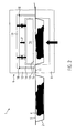
- Figur 1
- einen schematischen Vertikalschnitt durch ein erfindungsgemäßer Siegelwerkzeug,
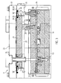
- Figur 2
- einen Vertikalschnitt durch das in
Figur 1 gezeigte, nun aber geschlossene Siegelwerkzeug, - Figur 3
- einen Vertikalschnitt durch eine mit einer Kolbenplatte verbundene Siegelplatte in einer angehobenen Stellung,
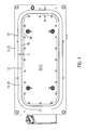
- Figur 4
- eine Draufsicht auf die in
Figur 3 gezeigte Kolbenplatte und Dichtung, und - Figur 5
- einen Vertikalschnitt durch die Siegelplatte und die Kolbenplatte gemäß
Figur 3 in einer abgesenkten Stellung der Siegelplatte. - Gleiche Komponenten sind in den Figuren durchgängig mit gleichen Bezugszeichen versehen.
-
Figur 1 zeigt einen Vertikalschnitt durch ein Ausführungsbeispiel eines erfindungsgemäßen Siegelwerkzeugs 1 in einer geöffneten Stellung. Im vorliegenden Ausführungsbeispiel ist dieses Siegelwerkzeug 1 integriert in eine Tiefzieh-Verpackungsmaschine. In der Verpackungsmaschine werden in einer Unterfolie 2 durch Tiefziehen Mulden 3 geformt, die dann mit einem Produkt 4 befüllt werden. Im Siegelwerkzeug sollen die Mulden 2 mit einer auf ihren Rand aufgelegten Deckelfolie 5 verschlossen werden, um versiegelte Verpackungen zu bilden. Die Deckelfolie 5 wird von einer Rolle 6 abgezogen und über Umlenkrollen 7 dem Siegelwerkzeug 1 zugeführt. - Das Siegelwerkzeug 1 verfügt über ein Unterteil 8 und ein Oberteil 9. Das Unterteil 8 des Siegelwerkzeugs 1 verfügt über eine Aufnahme 10, die groß genug ist zur Aufnahme einer Mulde 2. Die Ränder 11 der Verpackungsmulde 2 können dabei auf den Rändern des Siegelwerkzeug-Unterteils 8 aufliegen. Das Oberteil 9 des Siegelwerkzeugs verfügt über ein Siegelwerkzugaußenteil 12, das gemeinsam mit dem Siegelwerkzeug-Unterteil 8 eine Sigelkammer 13 öffnen und schließen kann. Relativ zum Siegelwerkzeugaußenteil 12 ist in dessen Inneren ein Siegelwerkzeuginnenteil 14 vorgesehen. Am umlaufenden unteren Rand des Siegelwerkzeuginnenteils 14 befindet sich der eigentliche Siegelrand 15. Wird dieser Siegelrand 15 auf die Verpackung abgesenkt und an die Verpackung angepresst, erfolgt entlang der Kontur des Siegelrandes 15 eine Versiegelung der Deckelfolie 5 mit der Unterfolie 2.
- Im Inneren des Siegelwerkzeuginnenteils 14 befindet sich eine Kühl- oder Produktschutzplatte 16. Über Kühlleitungen 17 wird sie von einem Kühlmedium durchströmt, so dass sie kühler ist als die erwärmte Siegelplatte 14. Auf diese Weise können empfindliche Produkte 4 während des Siegelns vor der Wärme der Siegelplatte 14 geschützt werden. Die Kühlleitungen 17 sind über Dichtungen 17' gegen die Siegelplatte 14 abgedichtet. An Stelle der Kühlleitungen 17 können auch Wärme ableitende Bolzen vorgesehen sein.
- Im ersten Ausführungsbeispiel ist die Siegelplatte bzw. das Siegelwerkzeuginnenteil 14 vertikal innerhalb des Siegelwerkzeugaußenteils 12 beweglich. Eine Dichtung 18 verläuft ringförmig zwischen der Oberseite der Siegelplatte 14 und dem Siegelwerkzeugaußenteil 12. Diese Dichtung ist als flächiges, ringförmiges Teil aus Silikon hergestellt. Ihre Außenkante ist am Siegelwerkzeugaußenteil 12 befestigt, während ihre Innenkante am Siegelwerkzeuginnenteil 14 befestigt ist. Der Raum 19 oberhalb des Siegelwerkzeuginnenteils 14, d. h. zwischen dem Siegelwerkzeugaußenteil 12 und dem Siegelwerkzeuginnenteil 14, kann mit Druckluft beaufschlagt werden. Diese Druckluft wirkt auf das Siegelwerkzeuginnenteil 14 und bewegt dieses relativ zum Siegelwerkzeugaußenteil 12 nach unten.
- Ein zweites, alternatives Ausführungsbeispiel des Siegelwerkzeugs 1 ist ebenfalls in
Figur 1 angedeutet. In diesen alternativen Ausführungsbeispiel fehlt die Dichtung 18 zwischen der Siegelplatte 14 und dem Siegelwerkzeugaußenteil 12. Stattdessen ist die Siegelplatte 14 über eine starre Verbindung (beispielsweise über Bolzen) 20 mit einer Kolbeneinrichtung oder Kolbenplatte 21 verbunden, die in einem oberhalb der Siegelkammer 13 zusätzlich vorgesehenen Kolbenkammer 22 beweglich gelagert ist. Die Wände 23 dieser zusätzlichen Kolbenkammer 22 bilden nun das Siegelwerkzeugaußenteil 12, während die Kolbenplatte 21 das bewegliche Siegelwerkzeuginnenteil bildet. - Die Dichtung 18' ist in diesem zweiten Ausführungsbeispiel zwischen den Außenwänden 23 der Kolbenkammer 22 und der Kolbenplatte 21 vorgesehen. Diese Dichtung 18', die ebenfalls als flacher Silikon-Ring ausgebildet sein kann, ist an ihrer Außenseite an den Wänden 23 der Kolbenkammer 22 befestigt, während ihre Innenkante an oder nahe der Außenkante der Kolbenplatte 21 befestigt ist. Der Bereich der Kolbenkammer 22 oberhalb der Kolbenplatte 21 kann mit Druckluft beaufschlagt werden, um die Kolbenplatte nach unten zu drücken. Wegen der Verbindung 20 folgt die Siegelplatte 14 dieser Bewegung der Kolbenplatte 21, um gegen den zu verschließenden Behälter angedrückt zu werden.
-
Figur 2 zeigt das Siegelwerkzeug 1 während des Siegelvorgangs selbst. Zu diesem Zweck ist zunächst die Siegelkammer 13 geschlossen worden, indem das Siegelwerkzeugunterteil 8 angehoben und von unten gegen den Rand 11 der Verpackungsmulde 2 angelegt worden. Gleichzeitig ist das Siegelwerkzeugoberteil 9 abgesenkt worden, um den Rand 11 der Verpackungen sowie die Deckelfolie 5 zwischen sich und dem Siegelwerkzeugunterteil 8 einzuklemmen. - Im nächsten Schritt ist - wie durch den Pfeil P angedeutet - das Siegelwerkzeuginnenteil 14 abgesenkt worden, indem der Raum 19 oberhalb der Siegelplatte 14 mit Druckluft gefüllt wurde. Auf diese Weise wird der erwärmte Siegelrand 15 an die Verpackungen angelegt und gleichzeitig der erforderliche Siegeldruck aufgebaut, um die Oberfolie 5 mit der Unterfolie 2 zu versiegeln.
-
Figur 3 zeigt in Vergrößerung das zweite Ausführungsbeispiel des Siegelwerkzeugoberteils 9, bei dem die Siegelplatte 14 über Bolzen 20 starr mit einer Kolbenplatte 21 verbunden ist. Diese Bolzen 20 sind über Schrauben 24 an einer mehrteiligen, beheizbaren Heizplatte 25 angeschraubt, die ihrerseits fest mit der Siegelplatte 14 verbunden ist. Ein flächiger Kontakt zwischen der Heizplatte 25 und der Siegelplatte 14 gewährleistet eine hohe Wärmeleitung von der Heizplatte 25 zur Siegelplatte 14. - Die Kolbenplatte 21 befindet sich in einer Kolbenkammer 22 oberhalb der Siegelkammer 13. Zwischen den Seiten der Kolbenplatte 21 und den Wänden 23 der Kolbenkammer 22 besteht ein Spalt 27 mit einer minimalen, gerade die Bewegung der Kolbenplatte 21 zulassenden Breite S. Oberhalb des Spaltes 27 verbindet die flächige, ringförmige Dichtung 18' die Kolbenplatte 21 (als Siegelwerkzeuginnenteil) und die Wand 23 der Kolbenkammer 22 (als Siegelwerkzeugaußenteil).
- Die Dichtung 18' verfügt über einen Außenwulst 28 und einen Innenwulst 29, die jeweils dicker sind als der mittlere Bereich der Dichtung 18'. Der Außenwulst 28 der Dichtung 18' ist aufgenommen in einem ersten Haltebereich 30 in der Wand 23 der Kolbenkammer 22. Dieser erste Haltebereich 30 ist als eine nach oben geöffnete Nut in einem unteren Stück 31 der Wand 23 ausgebildet, die nach dem Einlegen der Dichtung 18' durch eine obere Abdeckplatte 32 abgeschlossen wird, um den Außenwulst 28 der Dichtung 18' zu befestigen. Zwischen einer abgerundeten Kante 33 des unteren Wandstücks 31 und der Abdeckplatte 32 verbleibt gerade genug Platz zur Aufnahme des mittleren Abschnitts der Dichtung 18'. Zwischen dieser abgerundeten Kante 33 und der nach innen weisenden Kontur des unteren Wandstücks 31 ist eine Abschrägung oder Abstufung 34 vorgesehen, die in der Stellung gemäß
Figur 3 vom mittleren Abschnitt der Dichtung 18' überspannt wird. - Der Innenwulst 29 der Dichtung 18' ist in einem zweiten Haltebereich 35 befestigt, der als Nut in der Oberseite der Kolbenplatte 21 ausgebildet ist. Insbesondere ist der zweite Haltebereich 35 an oder (im dargestellten Ausführungsbeispiel) nahe der Außenkante bzw. der Außenkontur 36 des Sigelwerkzeuginnenteils 14, 21 angeordnet. "Nahe der Außenkante" bedeutet in diesem Zusammenhang, dass die Mitte des zweiten Haltebereichs 35 nicht weiter von der Außenkante 36 entfernt ist als beispielsweise zwei bis vier mal die Dicke des Innenwulstes 29, oder als fünf bis zehn mal die Dicke des mittleren Bereichs der Dichtung 18'.
-
Figur 4 zeigt eine Draufsicht auf das inFigur 3 gezeigte Siegelwerkzeugoberteil 9 nach Abnahme der Abdeckplatte 32. In der Mitte ist das etwa rechteckige, aber mit abgerundeten Ecken versehene Siegelwerkzeuginnenteil 14, 21 zu sehen (d. h. die Siegelplatte bzw. die Kolbenplatte). Durch den Spalt 27 mit konstanter Breite S ist das Siegelwerkzeuginnenteil 14, 21 getrennt vom Siegelwerkzeugaußenteil 12, 23 (d. h. der Außenwand der Siegelkammer 13 bzw. der Kolbenkammer 22). - Überbrückt wird der Spalt 27 durch die Dichtung 18, 18', deren ringförmiger Verlauf hier besonders gut zu erkennen ist. Darüber hinaus wird ersichtlich, dass sowohl die Außenkante 37, als auch die Innenkante 38 der ringförmigen Dichtung 18, 18' in Draufsicht kongruent sind zum Verlauf des Spalts 27, bzw. zur Außenkante oder Außenkontur 36 des Siegelwerkzeuginnenteils 14, 21. Die Breite B der Dichtung 18, 18' ist deutlich größer als die Breite S des Spalts 27.
-
Figur 5 zeigt das inFigur 3 dargestellte Siegelwerkzeugoberteil 9, nun jedoch in einer abgesenkten Position der Kolbenplatte 21 und der Siegelplatte 14. Dieses Absenken wird durchgeführt, indem über nicht dargestellte Kanäle Druckluft in den Raum der Kolbenkammer 22 oberhalb der Kolbenplatte 21 eingeleitet wird, und indem in der Siegelkammer 13 ein Unterdruck erzeugt wird. Die Druckdifferenz zwischen dem Unterdruck in der Siegelkammer 13 und dem Überdruck in der Kobenkammer 22 kann beispielsweise 1 oder 2 bar betragen. Diese Druckdifferenz führt dazu, dass sich die Kolbenplatte 21 gemeinsam mit der Siegelplatte 14 nach unten bewegt. - Die Dichtung 18' wird dabei gedehnt. Durch den oberhalb von ihr herrschenden Unterdruck legt sie sich an die Oberfläche der Abschrägung oder Abstufung 34 an. Diese Oberfläche hat einen gestreckten, S-förmigen Verlauf. Dieser Verlauf sorgt dafür, dass in der in
Figur 5 gezeigten, abgesenkten Stellung der Kobenplatte 21 die Oberseite der Kolbenplatte 21 zusammen mit der Oberfläche der Abschrägung 34 einen stetigen, stufenlosen Verlauf bildet. Die Dichtung 18' kann sich an diese Oberflächen anlegen, ohne an dem Spalt 27 eine Kante oder einen Knick zu erhalten. Auf diese Weise wird die Dehnung der Dichtung 18' gleichmäßig über Ihren gesamten mittleren Bereich zwischen den beiden Haltebereichen 30, 35 verteilt, sodass lokale, übermäßige Beanspruchungen vermieden werden. - Über Zugfedern 39 und/oder Druckfedern 40 ist das Siegelwerkzeuginnenteil 14 am Siegelwerkzeugaußenteil 12 aufgehängt. Sobald die Druckdifferenz zwischen der Siegelkammer 13 und der Kolbenkammer 22 abgebaut wird, beispielsweise durch Entlüften der Siegelkammer 13 und der Kolbenkammer 22, bringen die Federn 39, 40 die Siegelplatte 14 und (sofern vorhanden) die Kolbenplatte 21 wieder in die angehobene Ausgangsposition zurück.
- Ausgehend von den dargestellten Ausführungsbeispielen kann das erfindungsgemäße Siegelwerkzeug 1 auf vielfache Weise abgewandelt werden. Beispielsweise ist es möglich, die Kolbenplatte 21 nicht in einer separaten Kolbenkammer 22, sondern im oberen Bereich der Siegelkammer 13 selbst unterzubringen. Die relativen Abmessungen der Dichtung 18, 18', insbesondere das Verhältnis der Stärke der beiden Wulste 28, 29 zum mittleren Bereich, kann sich vom dargestellten Ausführungsbeispiel unterscheiden.
Claims (13)
- Siegelwerkzeug (1) für eine Verpackungsmaschine, wobei das Siegelwerkzeug (1) ein Siegelwerkzeugaußenteil (12, 23) aufweist, in dem ein Siegelwerkzeuginnenteil (14, 21) beweglich ist, und wobei eine Dichtung (18, 18') zwischen dem Siegelwerkzeugaußenteil (12, 23) und dem Siegelwerkzeuginnenteil (14, 21) vorgesehen ist, dadurch gekennzeichnet, dass die Dichtung (18, 18') flächig und ringförmig ausgebildet und sowohl in einem ersten Haltebereich (30) am Siegelwerkzeugaußenteil (12, 23), als auch in einem zweiten Haltebereich (35) am Siegelwerkzeuginnenteil (14, 21) befestigt ist, wobei der zweite Haltebereich (35) am Siegelwerkzeuginnenteil (14, 21) an oder nahe der Außenkante (36) des Siegelwerkzeuginnenteils (14, 21) angeordnet ist.
- Siegelwerkzeug nach Anspruch 1, dadurch gekennzeichnet, dass die Dichtung (18, 18') eine zum Verlauf der Außenkontur (36) des Siegelwerkzeuginnenteils (14, 21) kongruente Form aufweist.
- Siegelwerkzeug nach einem der vorangehenden Ansprüche, dadurch gekennzeichnet, dass die Dichtung (18, 18') ausgehend von einem entspannten Zustand dehnbar ist.
- Siegelwerkzeug nach einem der vorangehenden Ansprüche, dadurch gekennzeichnet, dass die Dichtung (18, 18') Silikon aufweist oder aus Silikon besteht.
- Siegelwerkzeug nach einem der vorangehenden Ansprüche, dadurch gekennzeichnet, dass die Dichtung (18, 18') eine konstante Breite (B) aufweist.
- Siegelwerkzeug nach einem der vorangehenden Ansprüche, dadurch gekennzeichnet, dass zwischen dem Siegelwerkzeugaußenteil (12, 23) und dem Siegelwerkzeuginnenteil (14, 21) ein Spalt (27) mit einer Spaltbreite (S) vorliegt, und dass der erste und der zweite Haltebereich (30, 35) in einer Projektion auf eine Ebene senkrecht zur Bewegungsrichtung (P) des Siegelwerkzeuginnenteils (14, 21) weiter voneinander entfernt sind als die Spaltbreite (S).
- Siegelwerkzeug nach einem der vorangehenden Ansprüche, dadurch gekennzeichnet, dass zwischen dem Siegelwerkzeugaußenteil (12, 23) und dem Siegelwerkzeuginnenteil (14, 21) ein Spalt (27) vorliegt, und dass der erste Haltebereich (30) gegenüber der Außenkante des Spalts (27) nach Außen versetzt ist.
- Siegelwerkzeug nach einem der vorangehenden Ansprüche, dadurch gekennzeichnet, dass zwischen dem Siegelwerkzeugaußenteil (12, 23) und dem Siegelwerkzeuginnenteil (14, 21) ein Spalt (27) vorliegt, und dass der zweite Haltebereich (35) gegenüber der Innenkante des Spalts (27) auf dem Siegelwerkzeuginnenteil (14, 21) nach Innen versetzt ist.
- Siegelwerkzeug nach einem der Ansprüche 6 bis 8, dadurch gekennzeichnet, dass zwischen zumindest einem der beiden Haltebereiche (30, 35) und dem Spalt (27) eine Abschrägung oder Abstufung (34) vorgesehen ist.
- Siegelwerkzeug nach Anspruch 9, dadurch gekennzeichnet, dass sich in einer Endstellung des Siegelwerkzeuginnenteils (14, 21) eine Oberfläche des Siegelwerkzeuginnenteils (14, 21) jenseits des Spalts (27) stetig fortsetzt mit der Oberfläche () der Abschrägung oder Abstufung (34).
- Siegelwerkzeug nach Anspruch 9, dadurch gekennzeichnet, dass die Dichtung (18, 18') in jeder Stellung während der Bewegung des Siegelwerkzeuginnenteils (14, 21) von der Abschrägung oder Abstufung (34) beabstandet bleibt.
- Siegelwerkzeug nach einem der Ansprüche 6 bis 11, dadurch gekennzeichnet, dass zwischen zumindest einem der beiden Haltebereiche (30, 35) und dem Spalt (27) eine Kante (33) mit einer Abrundung vorgesehen ist.
- Verpackungsmaschine mit einem Siegelwerkzeug (1) nach einem der vorangehenden Ansprüche.
Applications Claiming Priority (1)
| Application Number | Priority Date | Filing Date | Title |
|---|---|---|---|
| DE201010004635 DE102010004635B4 (de) | 2010-01-14 | 2010-01-14 | Siegelwerkzeug |
Publications (2)
| Publication Number | Publication Date |
|---|---|
| EP2345527A1 true EP2345527A1 (de) | 2011-07-20 |
| EP2345527B1 EP2345527B1 (de) | 2014-04-09 |
Family
ID=43735967
Family Applications (1)
| Application Number | Title | Priority Date | Filing Date |
|---|---|---|---|
| EP20110000166 Active EP2345527B1 (de) | 2010-01-14 | 2011-01-11 | Siegelwerkzeug |
Country Status (4)
| Country | Link |
|---|---|
| US (1) | US9003746B2 (de) |
| EP (1) | EP2345527B1 (de) |
| DE (1) | DE102010004635B4 (de) |
| ES (1) | ES2459744T3 (de) |
Cited By (1)
| Publication number | Priority date | Publication date | Assignee | Title |
|---|---|---|---|---|
| EP3608235A1 (de) * | 2018-08-09 | 2020-02-12 | MULTIVAC Sepp Haggenmüller SE & Co. KG | Siegelwerkzeug für eine verpackungsmaschine |
Families Citing this family (12)
| Publication number | Priority date | Publication date | Assignee | Title |
|---|---|---|---|---|
| DE102010004635B4 (de) * | 2010-01-14 | 2011-09-22 | Multivac Sepp Haggenmüller Gmbh & Co. Kg | Siegelwerkzeug |
| EP2441683B1 (de) * | 2010-10-12 | 2012-12-12 | MULTIVAC Sepp Haggenmüller GmbH & Co KG | Verschließstation und Verfahren zum Schneiden einer Deckelfolie |
| DE102011105513A1 (de) * | 2011-06-24 | 2012-12-27 | Multivac Sepp Haggenmüller Gmbh & Co. Kg | Verfahren und Siegelstation zum Versiegeln von Verpackungen |
| US20140165502A1 (en) * | 2011-07-01 | 2014-06-19 | Leung Chi Wah | Sealing Apparatus |
| DE102012006696A1 (de) * | 2012-03-30 | 2013-10-02 | Multivac Sepp Haggenmüller Gmbh & Co. Kg | Verpackungsmaschine mit einer Siegelvorrichtung |
| US20140116002A1 (en) * | 2012-10-26 | 2014-05-01 | Illinois Tool Works Inc. | Protective body, heat sealing system that includes the protective body, and method for providing the protective body |
| ES2655280T5 (es) | 2013-12-16 | 2021-11-03 | Cryovac Inc | Aparato de embalaje de un producto |
| ES2824455T3 (es) * | 2017-08-30 | 2021-05-12 | Multivac Haggenmueller Kg | Estación de sellado así como procedimiento para la producción de embalajes de película con esquina de apertura |
| EP4011603B1 (de) * | 2020-12-11 | 2024-10-09 | Weber Food Technology GmbH | Siegelstation |
| IT202100001751A1 (it) * | 2021-01-28 | 2022-07-28 | Bmb S R L | Testa riscaldante e saldante per macchine confezionatrici di prodotti in vaschetta |
| DE102021110382A1 (de) * | 2021-04-23 | 2022-10-27 | Multivac Sepp Haggenmüller Se & Co. Kg | Siegelstation mit einer Produktschutzplatte |
| DE102023124998A1 (de) * | 2023-09-15 | 2025-03-20 | Multivac Sepp Haggenmüller Se & Co. Kg | Siegeleinrichtung mit angetriebener Halteeinrichtung |
Citations (4)
| Publication number | Priority date | Publication date | Assignee | Title |
|---|---|---|---|---|
| US4282699A (en) * | 1979-08-27 | 1981-08-11 | The Mead Corporation | Heat sealing apparatus |
| DE3404451A1 (de) * | 1984-02-08 | 1985-08-14 | Multivac Sepp Haggenmüller KG, 8941 Wolfertschwenden | Verpackungsmaschine mit einer versiegelungsstation |
| DE19935623A1 (de) * | 1999-07-29 | 2001-02-01 | Kuesters Eduard Maschf | Vorrichtung zum Bearbeiten einer Materialbahn mit Ultraschall |
| EP2112070A2 (de) * | 2008-04-22 | 2009-10-28 | Ulma Packaging Technological Center, S.Coop. | Anstellvorrichtung für ein Werkzeug |
Family Cites Families (31)
| Publication number | Priority date | Publication date | Assignee | Title |
|---|---|---|---|---|
| US711210A (en) * | 1901-01-05 | 1902-10-14 | Beech Nut Packing Co | Jar-sealing apparatus. |
| US2230595A (en) * | 1937-03-04 | 1941-02-04 | Trico Products Corp | Motor vehicle accessory system |
| US3800502A (en) * | 1968-10-28 | 1974-04-02 | Sidaplax Nv | Closuring containers |
| US3590554A (en) * | 1969-09-16 | 1971-07-06 | Maryland Cup Corp | Capping machine |
| US3724161A (en) * | 1971-09-29 | 1973-04-03 | Sidaplax Nv | Closuring containers |
| US3792567A (en) * | 1971-12-07 | 1974-02-19 | Dixie Packaging Co Inc | Heat sealing machine |
| US3792566A (en) * | 1972-05-30 | 1974-02-19 | Phillips Petroleum Co | Closure applying apparatus |
| GB1440922A (en) * | 1972-09-07 | 1976-06-30 | Metal Box Co Ltd | Closure of containers |
| DE2636003C2 (de) * | 1976-08-11 | 1984-03-01 | Ludwig Schwerdtel GmbH, 8047 Karlsfeld | Vorrichtung zum Verschließen von Dosen mit jeweils einem Deckel unter Vakuum |
| GB8400750D0 (en) * | 1984-01-12 | 1984-02-15 | Ae Plc | Piston |
| US5155974A (en) * | 1986-09-03 | 1992-10-20 | Seawell North America, Inc. | Food packaging with gas between tensioned film & lid |
| SE467619B (sv) * | 1987-10-15 | 1992-08-17 | Plm Ab | Saett och anordning foer att vakuumfoersluta en behaallare |
| US4909022A (en) * | 1988-06-16 | 1990-03-20 | Continental Can Company, Inc. | Nest for container closing machine |
| US4991375A (en) * | 1988-11-14 | 1991-02-12 | Raque Food Systems, Inc. | Heat seal carrier assembly |
| US5056427A (en) * | 1989-03-15 | 1991-10-15 | Seiko Instruments Inc. | Sealing of cavity on reagent tray |
| US4989393A (en) * | 1989-12-22 | 1991-02-05 | Rutherford Engineering, Inc. | Machine for sealing cups with film |
| FR2669888B1 (fr) * | 1990-12-03 | 1993-10-22 | Erca Sa | Procede et dispositif de positionnement avant scellage d'une bande de couvercles sur un ensemble de recipients. |
| JPH0512844U (ja) * | 1991-07-30 | 1993-02-19 | 日東工器株式会社 | シ−ルリング |
| US5689937A (en) * | 1993-11-18 | 1997-11-25 | World Class Packaging Systems, Inc. | Method for packing food |
| US6351928B2 (en) * | 1996-12-17 | 2002-03-05 | Minipack Torre S.P.A. | Device for packaging products in containers sealed with stretchable plastic film |
| GB2322825A (en) * | 1997-03-03 | 1998-09-09 | Merck & Co Inc | Welding process for sealing containers |
| US7121402B2 (en) * | 2003-04-09 | 2006-10-17 | Reactive Nano Technologies, Inc | Container hermetically sealed with crushable material and reactive multilayer material |
| US20030196412A1 (en) * | 2002-04-19 | 2003-10-23 | Foulke Guy L. | Top formed packaging |
| DE10237933A1 (de) * | 2002-08-14 | 2004-02-26 | Multivac Sepp Haggenmüller Gmbh & Co. Kg | Verfahren und Verpackungsmaschine zum Verpacken eines in einer Schale befindlichen Produktes |
| JP4352166B2 (ja) * | 2003-04-17 | 2009-10-28 | 四国化工機株式会社 | 容器密封装置 |
| DE102008035994A1 (de) * | 2008-08-01 | 2010-02-11 | Multivac Sepp Haggenmüller Gmbh & Co. Kg | Verpackungsmaschine mit einer Ultraschallvorrichtung |
| DE102009020898B4 (de) * | 2009-05-13 | 2014-05-28 | Multivac Sepp Haggenmüller Gmbh & Co. Kg | Tiefziehverpackungsmaschine für mehrlagige Deckelfolie |
| DE102010004635B4 (de) * | 2010-01-14 | 2011-09-22 | Multivac Sepp Haggenmüller Gmbh & Co. Kg | Siegelwerkzeug |
| DE102011105513A1 (de) * | 2011-06-24 | 2012-12-27 | Multivac Sepp Haggenmüller Gmbh & Co. Kg | Verfahren und Siegelstation zum Versiegeln von Verpackungen |
| EP2594496B1 (de) * | 2011-11-17 | 2015-04-08 | Cryovac, Inc. | Verpackungsvorrichtung mit Schneidgerät zum Schneiden einer Folie |
| US20140116002A1 (en) * | 2012-10-26 | 2014-05-01 | Illinois Tool Works Inc. | Protective body, heat sealing system that includes the protective body, and method for providing the protective body |
-
2010
- 2010-01-14 DE DE201010004635 patent/DE102010004635B4/de active Active
-
2011
- 2011-01-11 EP EP20110000166 patent/EP2345527B1/de active Active
- 2011-01-11 ES ES11000166T patent/ES2459744T3/es active Active
- 2011-01-14 US US13/007,101 patent/US9003746B2/en active Active
Patent Citations (4)
| Publication number | Priority date | Publication date | Assignee | Title |
|---|---|---|---|---|
| US4282699A (en) * | 1979-08-27 | 1981-08-11 | The Mead Corporation | Heat sealing apparatus |
| DE3404451A1 (de) * | 1984-02-08 | 1985-08-14 | Multivac Sepp Haggenmüller KG, 8941 Wolfertschwenden | Verpackungsmaschine mit einer versiegelungsstation |
| DE19935623A1 (de) * | 1999-07-29 | 2001-02-01 | Kuesters Eduard Maschf | Vorrichtung zum Bearbeiten einer Materialbahn mit Ultraschall |
| EP2112070A2 (de) * | 2008-04-22 | 2009-10-28 | Ulma Packaging Technological Center, S.Coop. | Anstellvorrichtung für ein Werkzeug |
Cited By (1)
| Publication number | Priority date | Publication date | Assignee | Title |
|---|---|---|---|---|
| EP3608235A1 (de) * | 2018-08-09 | 2020-02-12 | MULTIVAC Sepp Haggenmüller SE & Co. KG | Siegelwerkzeug für eine verpackungsmaschine |
Also Published As
| Publication number | Publication date |
|---|---|
| US20110167762A1 (en) | 2011-07-14 |
| ES2459744T3 (es) | 2014-05-12 |
| EP2345527B1 (de) | 2014-04-09 |
| US9003746B2 (en) | 2015-04-14 |
| DE102010004635A1 (de) | 2011-07-21 |
| DE102010004635B4 (de) | 2011-09-22 |
Similar Documents
| Publication | Publication Date | Title |
|---|---|---|
| EP2345527B1 (de) | Siegelwerkzeug | |
| EP1997613B1 (de) | Mehretagen-Laminierpresse | |
| WO2019137907A1 (de) | Faltschachtelstapel-umsetzvorrichtung in einer verpackungsmaschine und verfahren zum umsetzen eines faltschachtelstapels in einer verpackungsmaschine | |
| DE60204133T2 (de) | Verfahren und Vorrichtung zur Herstellung von Beuteln | |
| EP2384981B1 (de) | Siegelstation für eine Verpackungsmaschine | |
| EP3581516A1 (de) | Skinverpackung sowie verfahren und siegelstation zur herstellung einer skinverpackung | |
| DE102007035032A1 (de) | Feinschneidpresse | |
| DE102014003229B4 (de) | Energieeffiziente vorgespannte Kompaktpresse | |
| EP2412637B1 (de) | Verpackungsmaschine mit mehreren Arbeitsstationen | |
| DE2546944C3 (de) | Heißplattenpresse mit Dehnkörper und Verfahren zur Herstellung desselben | |
| DE2843894A1 (de) | Vakuumstation | |
| DE102010003368A1 (de) | Verfahren zur Herstellung von Werkstoffplatten in einer kontinuierlich arbeitende Presse und eine kontinuierlich arbeitende Presse | |
| DE102009015893A1 (de) | Verfahren zur Herstellung von Werkstoffplatten in einer kontinuierlich arbeitende Presse und eine kontinuierlich arbeitende Presse | |
| DE4424845C2 (de) | Abdeckplatte für Vakuumformmaschinen | |
| DE69003218T2 (de) | Verfahren zum zusätzlichen Befestigen des Werkzeuges einer Plattenpresse. | |
| DE102009023581A1 (de) | Presse, insbesondere kontinuierlich arbeitende Presse zur Herstellung von Werkstoffplatten | |
| DE19856950A1 (de) | Vorrichtung und Verfahren zur Herstellung von Sickenblechen mit mehreren geschlossenen Sicken | |
| DE10033246A1 (de) | Pressvorrichtung zur mehrseitigen Beschichtung von Werkstücken, insbesondere Möbelteilen | |
| DE102009023577A1 (de) | Presse, insbesondere kontinuierlich arbeitende Presse zur Herstellung von Werkstoffplatten | |
| WO1985003487A1 (fr) | Emballeuse avec une station de scellement | |
| WO2022002968A2 (de) | Siegelwerkzeug mit einem heizmittel | |
| EP3450134B1 (de) | Formstation für eine tiefziehverpackungsmaschine und verfahren zum wechseln eines formstempels | |
| DE202016007676U1 (de) | Tiefziehverpackungsmaschine | |
| DE19750075A1 (de) | Verfahren und Vorrichtung zum Herstellen und Aufbringen von Deckeln aus einer Werkstoffbahn, insbesondere Deckblattfolien aus einer dünnen Kunststoffolienbahn | |
| DE3725007A1 (de) | Viel-platten-presse zum herstellen von laminaten unter unterdruck |
Legal Events
| Date | Code | Title | Description |
|---|---|---|---|
| PUAI | Public reference made under article 153(3) epc to a published international application that has entered the european phase |
Free format text: ORIGINAL CODE: 0009012 |
|
| AK | Designated contracting states |
Kind code of ref document: A1 Designated state(s): AL AT BE BG CH CY CZ DE DK EE ES FI FR GB GR HR HU IE IS IT LI LT LU LV MC MK MT NL NO PL PT RO RS SE SI SK SM TR |
|
| AX | Request for extension of the european patent |
Extension state: BA ME |
|
| 17P | Request for examination filed |
Effective date: 20110901 |
|
| REG | Reference to a national code |
Ref country code: DE Ref legal event code: R079 Ref document number: 502011002638 Country of ref document: DE Free format text: PREVIOUS MAIN CLASS: B29C0065180000 Ipc: B65B0007160000 |
|
| GRAP | Despatch of communication of intention to grant a patent |
Free format text: ORIGINAL CODE: EPIDOSNIGR1 |
|
| RIC1 | Information provided on ipc code assigned before grant |
Ipc: B65B 7/16 20060101AFI20130709BHEP Ipc: B29C 65/18 20060101ALN20130709BHEP Ipc: F16J 9/00 20060101ALN20130709BHEP Ipc: B65B 51/14 20060101ALN20130709BHEP Ipc: B30B 1/38 20060101ALN20130709BHEP Ipc: B65D 77/20 20060101ALN20130709BHEP |
|
| RIC1 | Information provided on ipc code assigned before grant |
Ipc: B65D 77/20 20060101ALN20130722BHEP Ipc: B30B 1/38 20060101ALN20130722BHEP Ipc: F16J 9/00 20060101ALN20130722BHEP Ipc: B29C 65/18 20060101ALN20130722BHEP Ipc: B65B 51/14 20060101ALN20130722BHEP Ipc: B65B 7/16 20060101AFI20130722BHEP |
|
| INTG | Intention to grant announced |
Effective date: 20130807 |
|
| GRAS | Grant fee paid |
Free format text: ORIGINAL CODE: EPIDOSNIGR3 |
|
| GRAA | (expected) grant |
Free format text: ORIGINAL CODE: 0009210 |
|
| AK | Designated contracting states |
Kind code of ref document: B1 Designated state(s): AL AT BE BG CH CY CZ DE DK EE ES FI FR GB GR HR HU IE IS IT LI LT LU LV MC MK MT NL NO PL PT RO RS SE SI SK SM TR |
|
| REG | Reference to a national code |
Ref country code: GB Ref legal event code: FG4D Free format text: NOT ENGLISH |
|
| REG | Reference to a national code |
Ref country code: CH Ref legal event code: NV Representative=s name: BOVARD AG, CH Ref country code: AT Ref legal event code: REF Ref document number: 661209 Country of ref document: AT Kind code of ref document: T Effective date: 20140415 Ref country code: CH Ref legal event code: EP |
|
| REG | Reference to a national code |
Ref country code: ES Ref legal event code: FG2A Ref document number: 2459744 Country of ref document: ES Kind code of ref document: T3 Effective date: 20140512 |
|
| REG | Reference to a national code |
Ref country code: IE Ref legal event code: FG4D Free format text: LANGUAGE OF EP DOCUMENT: GERMAN |
|
| REG | Reference to a national code |
Ref country code: DE Ref legal event code: R096 Ref document number: 502011002638 Country of ref document: DE Effective date: 20140522 |
|
| REG | Reference to a national code |
Ref country code: NL Ref legal event code: VDEP Effective date: 20140409 |
|
| REG | Reference to a national code |
Ref country code: LT Ref legal event code: MG4D |
|
| PG25 | Lapsed in a contracting state [announced via postgrant information from national office to epo] |
Ref country code: BG Free format text: LAPSE BECAUSE OF FAILURE TO SUBMIT A TRANSLATION OF THE DESCRIPTION OR TO PAY THE FEE WITHIN THE PRESCRIBED TIME-LIMIT Effective date: 20140709 Ref country code: LT Free format text: LAPSE BECAUSE OF FAILURE TO SUBMIT A TRANSLATION OF THE DESCRIPTION OR TO PAY THE FEE WITHIN THE PRESCRIBED TIME-LIMIT Effective date: 20140409 Ref country code: FI Free format text: LAPSE BECAUSE OF FAILURE TO SUBMIT A TRANSLATION OF THE DESCRIPTION OR TO PAY THE FEE WITHIN THE PRESCRIBED TIME-LIMIT Effective date: 20140409 Ref country code: NL Free format text: LAPSE BECAUSE OF FAILURE TO SUBMIT A TRANSLATION OF THE DESCRIPTION OR TO PAY THE FEE WITHIN THE PRESCRIBED TIME-LIMIT Effective date: 20140409 Ref country code: NO Free format text: LAPSE BECAUSE OF FAILURE TO SUBMIT A TRANSLATION OF THE DESCRIPTION OR TO PAY THE FEE WITHIN THE PRESCRIBED TIME-LIMIT Effective date: 20140709 Ref country code: IS Free format text: LAPSE BECAUSE OF FAILURE TO SUBMIT A TRANSLATION OF THE DESCRIPTION OR TO PAY THE FEE WITHIN THE PRESCRIBED TIME-LIMIT Effective date: 20140809 Ref country code: GR Free format text: LAPSE BECAUSE OF FAILURE TO SUBMIT A TRANSLATION OF THE DESCRIPTION OR TO PAY THE FEE WITHIN THE PRESCRIBED TIME-LIMIT Effective date: 20140710 |
|
| PG25 | Lapsed in a contracting state [announced via postgrant information from national office to epo] |
Ref country code: SE Free format text: LAPSE BECAUSE OF FAILURE TO SUBMIT A TRANSLATION OF THE DESCRIPTION OR TO PAY THE FEE WITHIN THE PRESCRIBED TIME-LIMIT Effective date: 20140409 Ref country code: PL Free format text: LAPSE BECAUSE OF FAILURE TO SUBMIT A TRANSLATION OF THE DESCRIPTION OR TO PAY THE FEE WITHIN THE PRESCRIBED TIME-LIMIT Effective date: 20140409 Ref country code: RS Free format text: LAPSE BECAUSE OF FAILURE TO SUBMIT A TRANSLATION OF THE DESCRIPTION OR TO PAY THE FEE WITHIN THE PRESCRIBED TIME-LIMIT Effective date: 20140409 Ref country code: HR Free format text: LAPSE BECAUSE OF FAILURE TO SUBMIT A TRANSLATION OF THE DESCRIPTION OR TO PAY THE FEE WITHIN THE PRESCRIBED TIME-LIMIT Effective date: 20140409 Ref country code: LV Free format text: LAPSE BECAUSE OF FAILURE TO SUBMIT A TRANSLATION OF THE DESCRIPTION OR TO PAY THE FEE WITHIN THE PRESCRIBED TIME-LIMIT Effective date: 20140409 |
|
| PG25 | Lapsed in a contracting state [announced via postgrant information from national office to epo] |
Ref country code: PT Free format text: LAPSE BECAUSE OF FAILURE TO SUBMIT A TRANSLATION OF THE DESCRIPTION OR TO PAY THE FEE WITHIN THE PRESCRIBED TIME-LIMIT Effective date: 20140811 |
|
| REG | Reference to a national code |
Ref country code: DE Ref legal event code: R097 Ref document number: 502011002638 Country of ref document: DE |
|
| PG25 | Lapsed in a contracting state [announced via postgrant information from national office to epo] |
Ref country code: SK Free format text: LAPSE BECAUSE OF FAILURE TO SUBMIT A TRANSLATION OF THE DESCRIPTION OR TO PAY THE FEE WITHIN THE PRESCRIBED TIME-LIMIT Effective date: 20140409 Ref country code: EE Free format text: LAPSE BECAUSE OF FAILURE TO SUBMIT A TRANSLATION OF THE DESCRIPTION OR TO PAY THE FEE WITHIN THE PRESCRIBED TIME-LIMIT Effective date: 20140409 Ref country code: DK Free format text: LAPSE BECAUSE OF FAILURE TO SUBMIT A TRANSLATION OF THE DESCRIPTION OR TO PAY THE FEE WITHIN THE PRESCRIBED TIME-LIMIT Effective date: 20140409 Ref country code: RO Free format text: LAPSE BECAUSE OF FAILURE TO SUBMIT A TRANSLATION OF THE DESCRIPTION OR TO PAY THE FEE WITHIN THE PRESCRIBED TIME-LIMIT Effective date: 20140409 Ref country code: CZ Free format text: LAPSE BECAUSE OF FAILURE TO SUBMIT A TRANSLATION OF THE DESCRIPTION OR TO PAY THE FEE WITHIN THE PRESCRIBED TIME-LIMIT Effective date: 20140409 |
|
| PLBE | No opposition filed within time limit |
Free format text: ORIGINAL CODE: 0009261 |
|
| STAA | Information on the status of an ep patent application or granted ep patent |
Free format text: STATUS: NO OPPOSITION FILED WITHIN TIME LIMIT |
|
| 26N | No opposition filed |
Effective date: 20150112 |
|
| REG | Reference to a national code |
Ref country code: DE Ref legal event code: R097 Ref document number: 502011002638 Country of ref document: DE Effective date: 20150112 |
|
| PG25 | Lapsed in a contracting state [announced via postgrant information from national office to epo] |
Ref country code: BE Free format text: LAPSE BECAUSE OF NON-PAYMENT OF DUE FEES Effective date: 20150131 |
|
| PG25 | Lapsed in a contracting state [announced via postgrant information from national office to epo] |
Ref country code: SI Free format text: LAPSE BECAUSE OF FAILURE TO SUBMIT A TRANSLATION OF THE DESCRIPTION OR TO PAY THE FEE WITHIN THE PRESCRIBED TIME-LIMIT Effective date: 20140409 |
|
| PG25 | Lapsed in a contracting state [announced via postgrant information from national office to epo] |
Ref country code: LU Free format text: LAPSE BECAUSE OF FAILURE TO SUBMIT A TRANSLATION OF THE DESCRIPTION OR TO PAY THE FEE WITHIN THE PRESCRIBED TIME-LIMIT Effective date: 20150111 |
|
| GBPC | Gb: european patent ceased through non-payment of renewal fee |
Effective date: 20150111 |
|
| PG25 | Lapsed in a contracting state [announced via postgrant information from national office to epo] |
Ref country code: MC Free format text: LAPSE BECAUSE OF FAILURE TO SUBMIT A TRANSLATION OF THE DESCRIPTION OR TO PAY THE FEE WITHIN THE PRESCRIBED TIME-LIMIT Effective date: 20140409 |
|
| PG25 | Lapsed in a contracting state [announced via postgrant information from national office to epo] |
Ref country code: GB Free format text: LAPSE BECAUSE OF NON-PAYMENT OF DUE FEES Effective date: 20150111 |
|
| REG | Reference to a national code |
Ref country code: IE Ref legal event code: MM4A |
|
| REG | Reference to a national code |
Ref country code: FR Ref legal event code: PLFP Year of fee payment: 6 |
|
| PG25 | Lapsed in a contracting state [announced via postgrant information from national office to epo] |
Ref country code: IE Free format text: LAPSE BECAUSE OF NON-PAYMENT OF DUE FEES Effective date: 20150111 |
|
| REG | Reference to a national code |
Ref country code: DE Ref legal event code: R082 Ref document number: 502011002638 Country of ref document: DE Representative=s name: GRUENECKER PATENT- UND RECHTSANWAELTE PARTG MB, DE Ref country code: DE Ref legal event code: R081 Ref document number: 502011002638 Country of ref document: DE Owner name: MULTIVAC SEPP HAGGENMUELLER SE & CO. KG, DE Free format text: FORMER OWNER: MULTIVAC SEPP HAGGENMUELLER GMBH & CO. KG, 87787 WOLFERTSCHWENDEN, DE |
|
| PG25 | Lapsed in a contracting state [announced via postgrant information from national office to epo] |
Ref country code: MT Free format text: LAPSE BECAUSE OF FAILURE TO SUBMIT A TRANSLATION OF THE DESCRIPTION OR TO PAY THE FEE WITHIN THE PRESCRIBED TIME-LIMIT Effective date: 20140409 |
|
| REG | Reference to a national code |
Ref country code: FR Ref legal event code: PLFP Year of fee payment: 7 |
|
| REG | Reference to a national code |
Ref country code: AT Ref legal event code: MM01 Ref document number: 661209 Country of ref document: AT Kind code of ref document: T Effective date: 20160111 |
|
| PG25 | Lapsed in a contracting state [announced via postgrant information from national office to epo] |
Ref country code: SM Free format text: LAPSE BECAUSE OF FAILURE TO SUBMIT A TRANSLATION OF THE DESCRIPTION OR TO PAY THE FEE WITHIN THE PRESCRIBED TIME-LIMIT Effective date: 20140409 Ref country code: AT Free format text: LAPSE BECAUSE OF NON-PAYMENT OF DUE FEES Effective date: 20160111 Ref country code: HU Free format text: LAPSE BECAUSE OF FAILURE TO SUBMIT A TRANSLATION OF THE DESCRIPTION OR TO PAY THE FEE WITHIN THE PRESCRIBED TIME-LIMIT; INVALID AB INITIO Effective date: 20110111 |
|
| PG25 | Lapsed in a contracting state [announced via postgrant information from national office to epo] |
Ref country code: CY Free format text: LAPSE BECAUSE OF FAILURE TO SUBMIT A TRANSLATION OF THE DESCRIPTION OR TO PAY THE FEE WITHIN THE PRESCRIBED TIME-LIMIT Effective date: 20140409 |
|
| REG | Reference to a national code |
Ref country code: FR Ref legal event code: PLFP Year of fee payment: 8 |
|
| PG25 | Lapsed in a contracting state [announced via postgrant information from national office to epo] |
Ref country code: MK Free format text: LAPSE BECAUSE OF FAILURE TO SUBMIT A TRANSLATION OF THE DESCRIPTION OR TO PAY THE FEE WITHIN THE PRESCRIBED TIME-LIMIT Effective date: 20140409 |
|
| PG25 | Lapsed in a contracting state [announced via postgrant information from national office to epo] |
Ref country code: AL Free format text: LAPSE BECAUSE OF FAILURE TO SUBMIT A TRANSLATION OF THE DESCRIPTION OR TO PAY THE FEE WITHIN THE PRESCRIBED TIME-LIMIT Effective date: 20140409 |
|
| P01 | Opt-out of the competence of the unified patent court (upc) registered |
Effective date: 20230404 |
|
| PGFP | Annual fee paid to national office [announced via postgrant information from national office to epo] |
Ref country code: CH Payment date: 20240202 Year of fee payment: 14 |
|
| PGFP | Annual fee paid to national office [announced via postgrant information from national office to epo] |
Ref country code: TR Payment date: 20240110 Year of fee payment: 14 |
|
| REG | Reference to a national code |
Ref country code: CH Ref legal event code: PL |
|
| PG25 | Lapsed in a contracting state [announced via postgrant information from national office to epo] |
Ref country code: CH Free format text: LAPSE BECAUSE OF NON-PAYMENT OF DUE FEES Effective date: 20250131 |
|
| PGFP | Annual fee paid to national office [announced via postgrant information from national office to epo] |
Ref country code: ES Payment date: 20260217 Year of fee payment: 16 |
|
| PGFP | Annual fee paid to national office [announced via postgrant information from national office to epo] |
Ref country code: DE Payment date: 20260120 Year of fee payment: 16 |
|
| PGFP | Annual fee paid to national office [announced via postgrant information from national office to epo] |
Ref country code: IT Payment date: 20260130 Year of fee payment: 16 |
|
| PGFP | Annual fee paid to national office [announced via postgrant information from national office to epo] |
Ref country code: FR Payment date: 20260121 Year of fee payment: 16 |