EP2345461B1 - Golfballhülle mit Drehdetektor - Google Patents
Golfballhülle mit Drehdetektor Download PDFInfo
- Publication number
- EP2345461B1 EP2345461B1 EP10196367A EP10196367A EP2345461B1 EP 2345461 B1 EP2345461 B1 EP 2345461B1 EP 10196367 A EP10196367 A EP 10196367A EP 10196367 A EP10196367 A EP 10196367A EP 2345461 B1 EP2345461 B1 EP 2345461B1
- Authority
- EP
- European Patent Office
- Prior art keywords
- pigment
- ball
- outer layer
- golf ball
- cavity
- Prior art date
- Legal status (The legal status is an assumption and is not a legal conclusion. Google has not performed a legal analysis and makes no representation as to the accuracy of the status listed.)
- Not-in-force
Links
Images



Classifications
-
- A—HUMAN NECESSITIES
- A63—SPORTS; GAMES; AMUSEMENTS
- A63B—APPARATUS FOR PHYSICAL TRAINING, GYMNASTICS, SWIMMING, CLIMBING, OR FENCING; BALL GAMES; TRAINING EQUIPMENT
- A63B37/00—Solid balls; Rigid hollow balls; Marbles
- A63B37/0003—Golf balls
-
- A—HUMAN NECESSITIES
- A63—SPORTS; GAMES; AMUSEMENTS
- A63B—APPARATUS FOR PHYSICAL TRAINING, GYMNASTICS, SWIMMING, CLIMBING, OR FENCING; BALL GAMES; TRAINING EQUIPMENT
- A63B37/00—Solid balls; Rigid hollow balls; Marbles
- A63B37/0003—Golf balls
- A63B37/0022—Coatings, e.g. paint films; Markings
- A63B37/00223—Colour tone
-
- A—HUMAN NECESSITIES
- A63—SPORTS; GAMES; AMUSEMENTS
- A63B—APPARATUS FOR PHYSICAL TRAINING, GYMNASTICS, SWIMMING, CLIMBING, OR FENCING; BALL GAMES; TRAINING EQUIPMENT
- A63B43/00—Balls with special arrangements
- A63B43/008—Balls with special arrangements with means for improving visibility, e.g. special markings or colours
-
- A—HUMAN NECESSITIES
- A63—SPORTS; GAMES; AMUSEMENTS
- A63B—APPARATUS FOR PHYSICAL TRAINING, GYMNASTICS, SWIMMING, CLIMBING, OR FENCING; BALL GAMES; TRAINING EQUIPMENT
- A63B69/00—Training appliances or apparatus for special sports
- A63B69/36—Training appliances or apparatus for special sports for golf
- A63B69/3623—Training appliances or apparatus for special sports for golf for driving
- A63B69/3655—Balls, ball substitutes, or attachments on balls therefor
-
- A—HUMAN NECESSITIES
- A63—SPORTS; GAMES; AMUSEMENTS
- A63B—APPARATUS FOR PHYSICAL TRAINING, GYMNASTICS, SWIMMING, CLIMBING, OR FENCING; BALL GAMES; TRAINING EQUIPMENT
- A63B2220/00—Measuring of physical parameters relating to sporting activity
- A63B2220/30—Speed
- A63B2220/34—Angular speed
- A63B2220/35—Spin
-
- A—HUMAN NECESSITIES
- A63—SPORTS; GAMES; AMUSEMENTS
- A63B—APPARATUS FOR PHYSICAL TRAINING, GYMNASTICS, SWIMMING, CLIMBING, OR FENCING; BALL GAMES; TRAINING EQUIPMENT
- A63B37/00—Solid balls; Rigid hollow balls; Marbles
- A63B37/0003—Golf balls
- A63B37/007—Characteristics of the ball as a whole
- A63B37/0072—Characteristics of the ball as a whole with a specified number of layers
- A63B37/0074—Two piece balls, i.e. cover and core
-
- A—HUMAN NECESSITIES
- A63—SPORTS; GAMES; AMUSEMENTS
- A63B—APPARATUS FOR PHYSICAL TRAINING, GYMNASTICS, SWIMMING, CLIMBING, OR FENCING; BALL GAMES; TRAINING EQUIPMENT
- A63B37/00—Solid balls; Rigid hollow balls; Marbles
- A63B37/0003—Golf balls
- A63B37/007—Characteristics of the ball as a whole
- A63B37/0077—Physical properties
- A63B37/0091—Density distribution amongst the different ball layers
-
- A—HUMAN NECESSITIES
- A63—SPORTS; GAMES; AMUSEMENTS
- A63B—APPARATUS FOR PHYSICAL TRAINING, GYMNASTICS, SWIMMING, CLIMBING, OR FENCING; BALL GAMES; TRAINING EQUIPMENT
- A63B37/00—Solid balls; Rigid hollow balls; Marbles
- A63B37/0003—Golf balls
- A63B37/007—Characteristics of the ball as a whole
- A63B37/0077—Physical properties
- A63B37/0096—Spin rate
-
- A—HUMAN NECESSITIES
- A63—SPORTS; GAMES; AMUSEMENTS
- A63B—APPARATUS FOR PHYSICAL TRAINING, GYMNASTICS, SWIMMING, CLIMBING, OR FENCING; BALL GAMES; TRAINING EQUIPMENT
- A63B37/00—Solid balls; Rigid hollow balls; Marbles
- A63B37/12—Special coverings, i.e. outer layer material
Definitions
- the present embodiments relate general to a golf ball that appears to change color. More specifically, the present embodiments relate generally to a golf ball having an outer layer containing different pigment colors.
- a golfer can see the flight of a ball. Seeing the flight of the ball can assist a golfer in changing swing characteristics to create a different trajectory. It is also useful to see the flight path of the ball in order to locate the ball for further play. When the day is bright, it is often difficult to follow the flight of a white ball against the sky.
- a ball that improves both conditions by providing a ball that provides a different color contrast against the sky to assist a golfer in determining the flight path of a ball and that also assists a golfer in determining the spin of the ball.
- a golf ball having an outer composite layer is included.
- the outer composite layer includes an outer translucent layer, an inner layer, and a first pigment between the outer layer and the inner layer.
- a golf ball in another embodiment, includes a core and a cover.
- the core includes an inner layer.
- the cover is radially outward of the core and includes an outer layer and a pigment in a cavity between the inner layer and the outer layer.
- Dividers may be placed between the inner layer and the outer layer to separate the cavity into a first portion and a second portion. Differently colored pigments may be placed into each cavity portion.
- FIG. 1 is a cross-sectional view of an embodiment
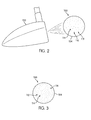
- FIG. 2 is a view showing a golf club and the embodiment of FIG. 1 just after impact;
- FIG. 3 is a view showing the ball of FIG. 1 after impact
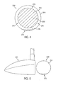
- FIG. 4 is a cross-sectional view of another embodiment
- FIG. 5 is a view showing a golf club and the embodiment of FIG. 4 at rest;
- FIG. 6 is a view showing the golf club and ball of FIG. 5 just after impact
- FIG. 7 is a view showing the ball of FIG. 4 after impact
- FIG. 8 is a cross-sectional view of another embodiment
- FIG. 9 is a detailed cross-sectional view of the embodiment of FIG. 8 ;
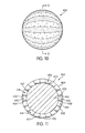
- FIG. 10 is a plan view of another embodiment
- FIG. 11 is a cross-sectional view of the embodiment of FIG. 10 ;
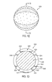
- FIG. 12 is a plan view of another embodiment.
- FIG. 13 is a cross-sectional view of the embodiment of FIG. 12 .
- the embodiments disclosed relate to golf balls that have varying configurations that include two pigments.
- the pigments are movable relative to each other and the outer surface and therefore, the apparent color of the ball changes depending on the spin of the ball.
- FIG. 1 is a cross section of an embodiment of golf ball 100.
- Golf ball 100 has a series of radially or circumferentially arranged layers.
- the innermost layer is core 102.
- Core 102 can be any of a variety of cores commonly used in golf balls.
- core 102 could be liquid filled or solid filled.
- the solid may be rubber, resin, or any other suitable material.
- the core may also include various types of weights.
- Core 102 may also include a wound cover.
- An optional mantle layer is not specifically shown in the FIGS., but may surround and may be positioned outward of core 102.
- Inner layer 103 is shown in FIG. 1 as being the outer surface of core 102, but may instead be defined by an outer surface of the optional mantle layer or another layer outward of core 102.
- Top or outer layer 104 is radially or circumferentially outward of the inner layer 103 and is shown in simplified form.
- the outer layer, and in particular, outer surface 106 of outer layer 104 is configured to be struck by a golf club.
- outer layer 104 may include various dimples, frets or lands, projections, printing, or any other features that a designer thinks would be desirable in affecting the flight path of the ball 100.
- Outer layer 104 may be designed to be scuff resistant.
- outer layer 104 is translucent.
- Inner layer 103 and outer layer 104 are spaced from one another and a space or cavity 108 is between the inner layer 103 and outer layer 104.
- First fluid 110 may have a variety of properties. However, it is desirable that the molecules or particles that comprise first fluid 110 be able to move in the cavity 108.
- First fluid 110 may be made of a variety of types of materials or of a single material. Some materials comprising first fluid 110 may have greater density or viscosity than others.
- First fluid 110 may include pigments having two colors. The two colors can be any two colors that are distinguishable from one another.
- First pigment 112 is a first color and second pigment 114 is a second color different from the first color.
- outer layer 104 of any of the disclosed embodiments may be translucent or transparent.
- a transparent ball is also translucent.
- the use of a first fluid having multiple colors is most useful if the color difference can be seen or determined through the outer layer.
- one pigment may be colored white.
- the selection of white as a color may be desirable so the ball retains the same general external appearance as a ball not equipped with the features of the varying embodiments.
- the outer layer is transparent, the other color may be any non-white color, but may desirably be orange.
- the outer layer is translucent, but not transparent, the other color must be selected to contrast sufficiently with the one pigment that the distinction is apparent through a translucent outer layer.
- one of the pigments is shown via stippling and another is shown by open space.
- a third pigment is shown by asterisks. While this manner of illustration in the FIGS. may give the appearance that only some of the pigments are made of individually distinguishable particles and others are not, the use of stippling for one color and lack of stippling for the other color is merely for ease of illustration and does not indicate a different sort of pigment.
- FIGS. illustrate layers having a variety of thicknesses. These thicknesses should not be considered to be the only possible thicknesses for the layers.
- the desirable thicknesses for the various layers depends on the materials a designer wishes to use and the protection or reactivity the designer wishes to provide by using the various layers. A person having ordinary skill in the art can modify the present embodiments to provide for a ball having layers of appropriate thicknesses.
- inner layer 103 and first pigment 112 are selected to mutually attract one another.
- one of the inner layer and the pigment could include a magnetic element and the other could include a magnetically active metal that is attracted to the magnetic element.
- inner layer 103 and first pigment 112 could have various types of ionic or other attraction that cause the first pigment to settle into a consolidated position along the surface of inner layer 103 when ball 100 is at rest. In such an instance, it may be desirable for inner layer 103 to be a separate layer from the core.
- the first pigment 112 may be a plurality of pigment particles 116.
- FIG. 2 is a schematic showing ball 100 just after impact by club 120.
- the impact of club 120 against ball 100 imparts a spin to ball 100.
- the spin imparted to the ball will create a force on each pigment particle 116 in first pigment 112.
- This force may be a centrifugal force, in whole or in part.
- the force may be sufficient to overcome the attractive force between first pigment 112 and inner layer 103. This may cause one or more of pigment particles 116 to leave the consolidated position shown in FIG. 1 and move to a dispersed position, as is shown by an exemplary pigment particle 118 visible through outer layer 104 among the particles of second pigment 114.
- FIG. 3 shows ball 100 after the first pigment 112 and first pigment particles 116 have reached a dispersed position.
- the density of first pigment particles 116 relative to particles of second pigment 114 measures the amount of spin imparted to ball 100 by the stroke of club 120. This measurement indicates to a golfer how much spin is applied or imparted to ball 100 by his or her stroke.
- first pigment 112 returns to the consolidated position shown in FIG. 1 after an effective length of time.
- the effective length of time will vary depending on factors such as the relative density of the first pigment and the second pigment, the amount of spin imparted to the ball, and the air temperature. These factors are not exclusive, but will depend on other factors as well.
- the pigments used may be of different and possibly contrasting colors. It may also be desirable for the pigments used to be UV reactive. In such an instance, the pigments would be arranged in the same manner as disclosed. However, when exposed to light from the sun or another UV source, the pigments would change from one color to another. In some instances, it may be desirable to select pigments that all appear white when not exposed to UV light in order to preserve an overall white appearance of the ball. In such an instance, when the ball is exposed to UV light during the course of play, the pigments would change color in flight and then could be capable of returning to a white color at rest. In such an instance, where the present disclosure refers to pigments having differing colors, these colors would be the colors that the pigments would have upon UV exposure, rather than their colors without such exposure.
- FIG. 4 is a cross section of an embodiment of golf ball 200.
- Golf ball 200 has a series of radially or circumferentially arranged layers.
- the innermost layer is core 202.
- Core or 202 has the same properties as described above in connection with core 102 and inner layer 203 has the same properties as described above in connection with inner layer 103.
- Top or outer layer 204 is radially or circumferentially outward of inner layer 203 and has the same properties as described above in connection with outer layer 104.
- Inner layer 203 and outer layer 204 are spaced from one another and a space or cavity 208 is between the inner layer 203 and outer layer 204.
- First fluid 210 may have a variety of properties. However, it is desirable that the molecules or particles that comprise first fluid 210 be able to move in the cavity 208. First fluid 210 may be made of a variety of types of materials or of a single material. Some materials comprising first fluid 210 may have greater density or viscosity than others. First fluid 210 may include pigments having two colors. The two colors can be any two colors that are distinguishable from one another. First pigment 212 is a first color and second pigment 214 is a second color different from the first color.
- first pigment 212 has settled to the bottom of cavity 208 in its consolidated position.
- pigment particles 216 of first pigment 212 may settle to the bottom of the cavity 208 is if first pigment particles 216 on average are of a higher density or weight than particles of second pigment 214.
- FIG. 5 shows ball 200 in its rest position just before it is struck by club 221.
- first pigment 212 is shown in its consolidated position on the bottom of ball 200.
- FIG. 6 shows ball 200 just after impact by club 221.
- the impact of club 221 against ball 200 imparts a spin to ball 200.
- the spin imparted to the ball will create a force on each pigment particle 216 in first pigment 212.
- This force may be a centrifugal force, in whole or in part.
- the force may be sufficient to cause one or more of pigment particles 216 to leave the consolidated position and move to a dispersed position, as is shown by an exemplary pigment particle 218 visible through outer layer 204 among the particles of second pigment 214.
- FIG. 7 shows ball 200 after the first pigment 212 and first pigment particles 216 have reached a dispersed position.
- the density and evenness of the distribution of first pigment particles 216 relative to particles of second pigment 214 measure the amount of spin imparted to ball 200 by the stroke of club 221. This measurement indicates to a golfer how much spin is applied or imparted to ball 200 by his or her stroke.
- first pigment 212 returns to the consolidated position shown in FIG. 4 after an effective length of time.
- the effective length of time will vary depending on factors such as the relative density of the first pigment and the second pigment, the amount of spin imparted to the ball, and the air temperature. These factors are not exclusive, but will depend on other factors as well.
- FIGS. 8-13 show other varying embodiments.
- Each of these embodiments shows a first pigment that settles to the bottom of a cavity or cavity portion similar to the embodiment shown in FIGS. 4-7 .
- the first pigment could instead be attracted to the inner layer, as shown in FIGS. 1-3 .
- some pigments may be selected to be attracted to the inner layer in some cavity sections and others to settle to the bottom of the cavity in other cavity sections. The placement of the pigments in the cavities and the precise formulation is left what a designer believes is useful or desirable.
- FIG. 8 shows a cross section of another embodiment of a golf ball 300.
- Golf ball 300 has a series of radially or circumferentially arranged layers.
- the innermost layer is core 302.
- Core 302 has the same properties as described above in connection with core 102 and inner layer 303 has the same properties as described above in connection with inner layer 103.
- Top or outer layer 304 is radially or circumferentially outward of inner layer 303 and has the same properties as described above in connection with outer layer 104.
- Inner layer 303 and outer layer 304 are spaced from one another and a space or cavity 308 is between the inner layer 303 and outer layer 304.
- a fluid may be present in cavity 308.
- divider 322 in ball 300 extending between inner layer 303 and outer layer 304.
- Divider 322 is shown in FIG. 8 as being annular and placed around a circumference of ball 300.
- Divider 322 divides cavity 308 into two substantially equal portions, specifically, first cavity portion 324 and second cavity portion 326.
- the use of a divider need not so separate cavity 308 and may instead separate cavity 308 into two dissimilarly sized portions.
- a divider could instead be used that is localized in a particular point or region and does not function as a divider.
- the divider may be considered to be a separator, separating the cavity into a plurality of spaces or separating the inner layer from the outer layer.
- FIG. 8 shows one possible rest position of ball 300; if ball 300 fell at a different angle to the ground, divider 322 would be positioned at a different angle relative to the ground.
- FIG. 9 is a closer view of one portion of ball 300.
- FIGS. 8 and 9 show the use of first pigment 312 and second pigment 314.
- First pigment 312 and second pigment 314 have the same properties as described above in connection with first pigment 112 and second pigment 114, respectively.
- ball 300 is in a rest position and first pigment 312 has settled to the bottom of each of first cavity portion 324 and second cavity portion 326 in its consolidated position.
- pigment particles 316 of first pigment 312 may settle to the bottom of first cavity portion 324 and second cavity portion 326 is if first pigment particles 316 on average are of a higher density or weight than particles of second pigment 314.
- first pigment particles 316 When ball 300 is struck, first pigment particles 316 will disperse more evenly into second pigment 314 in a dispersed position. The greater weight or density of first pigment 312 may cause the first pigment to be more greatly affected by the spin and to disperse more towards outer layer 304, causing them to be visible over a greater portion of outer layer 304. When ball 300 comes to its next rest position, first pigment 312 will again settle to the bottom of each of first cavity portion 324 and second cavity portion 326.
- FIGS. 10 and 11 show another embodiment of a golf ball 400.
- FIG. 10 shows a plan view of golf ball 400 with pigments in a dispersed position
- FIG. 11 shows a cross section of golf ball 400 with pigments in a consolidated position.
- Golf ball 400 has a series of radially or circumferentially arranged layers.
- the innermost layer is core 402.
- Core 402 has the same properties as described above in connection with core 102 and inner layer 403 has the same properties as described above in connection with inner layer 103.
- Top or outer layer 404 is radially or circumferentially outward of inner layer 403 and has the same properties as described above in connection with outer layer 104.
- Inner layer 403 and outer layer 404 are spaced from one another and a space or cavity 408 is between inner layer 403 and outer layer 404.
- a fluid may be present in the cavity 408.
- First divider 430 is shown in FIG. 11 as being annular and placed around a circumference of ball 400.
- Second divider 432 is annular and spaced from and adjacent to first divider 430.
- Third divider 434 is annular and spaced from and adjacent to first divider 430 and on the opposite side of first divider 430 from second divider 432.
- a plurality of equally spaced dividers is shown.
- First divider 430, second divider 432, and third divider 434 divide cavity 408 into portions, including first cavity portion 440 and second cavity portion 442. Each pair of adjacent dividers similarly provides a cavity portion therebetween in the embodiment shown in FIGS. 10 and 11.
- FIG. 11 shows one possible rest position of ball 400.
- FIGS. 10 and 11 show the use of first pigment 412, second pigment 414, and third pigment 417.
- First pigment 412 and third pigment 417 generally have the same properties as described above in connection with first pigment 112.
- Second pigment 414 generally has the same properties as described above in connection with second pigment 114.
- ball 400 is in a rest position and first pigment 412 and third pigment 417 have settled to the bottom of each of first cavity portion 440 and second cavity portion 442, respectively, in a consolidated position.
- First pigment 412 is on a first side of divider 430 and third pigment 417 is on a second side of divider 430.
- first pigment 412 is on a first side of divider 432 and third pigment 417 is on a second side of divider 432.
- pigment particles of first pigment 412 may settle to the bottom of first cavity portion 440 and third pigment 417 may settle to the bottom of the second cavity portion 442 is if pigment particles of first pigment 412 and third pigment 417 on average are of a higher density or weight than particles of second pigment 414.
- pigment particles of first pigment 412 and third pigment 417 will disperse more evenly into second pigment 414 in a dispersed position, such as that shown in FIG. 10 .
- first pigment 412 and third pigment 417 may cause the first pigment and third pigment to be more greatly affected by the spin and to disperse more towards outer layer 404, possibly due in whole or in part to centrifugal force, causing them to be visible over a greater portion of outer layer 404.
- first pigment 412 will again settle to the bottom of first cavity portion 440 and third pigment 417 will again settle to the bottom of second cavity portion 442.
- FIG. 10 shows a striped pattern that may emerge when first pigment 412 and third pigment 417 are spun outwardly to a dispersed position, possibly created entirely or in part by centrifugal force by the rotation of the ball due to backspin.
- the use of such a pattern may allow ball 400 to have a reduced wait time before it may be struck again.
- the first pigment When a ball having no dividers is used, the first pigment must return to a rest position without a boundary, which may be traveling a significant portion of the diameter of the ball without a diameter.
- the pigment may only need to travel a short distance to return to a consolidated position.
- the use of a striped pattern may also be useful to determine spin more accurately.
- First pigment 412 may have a first color
- second pigment 414 may have a second color
- third pigment 417 may have a third color.
- the first color, second color, and third color may all be different from one another.
- the first color and the third color may be generally primary colors that combine to form a secondary color.
- the first color could be blue and the third color could be yellow, which would form green.
- the color visible to the eye would vary depending on the spin of the ball and the varying weights of the pigments. For example, a more blue-green could indicate a particular type of spin, while a yellow-green could indicate a different type of spin. This information may be useful to a golfer in changing stroke characteristics.
- FIGS. 12 and 13 show another embodiment of a golf ball 500.
- FIG. 12 shows a plan view of golf ball 500 with pigments in a dispersed position
- FIG. 13 shows a cross section of golf ball 500 with pigments in a consolidated position.
- Golf ball 500 has a series of radially or circumferentially arranged layers.
- the innermost layer is core 502.
- Core 502 has the same properties as described above in connection with core 102 and inner layer 503 has the same properties as described above in connection with inner layer 103.
- Top or outer layer 504 is radially or circumferentially outward of inner layer 503 and has the same properties as described above in connection with outer layer 104.
- Inner layer 503 and outer layer 504 are spaced from one another and a space or cavity 508 is between inner layer 503 and outer layer 504. A fluid may be present in the cavity 508.
- First divider 550 is shown in FIG. 13 as being annular and placed around a circumference of ball 500.
- Second divider 552 is annular and spaced from and adjacent to first divider 550.
- Third divider 554 is annular and spaced from and adjacent to first divider 550 and on the opposite side of first divider 550 from second divider 552.
- the dividers are regularly, but unevenly, spaced.
- First divider 550, second divider 552, and third divider 554 divide cavity 508 into portions, specifically first cavity portion 560 and second cavity portion 562. Each pair of adjacent dividers similarly provides a cavity portion therebetween in the embodiment shown in FIGS. 12 and 13.
- FIG. 13 shows one possible rest position of ball 500.
- FIGS. 12 and 13 show the use of first pigment 512, second pigment 514, and third pigment 517.
- First pigment 512 and third pigment 517 generally have the same properties as described above in connection with first pigment 112.
- Second pigment 514 generally has the same properties as described above in connection with second pigment 114.
- ball 500 is in a rest position and first pigment 512 and third pigment 517 have settled to the bottom of each of first cavity portion 560 and second cavity portion 562, respectively, in a consolidated position.
- First pigment 512 is on a first side of divider 550 and third pigment 517 is on a second side of divider 550.
- first pigment 512 is on a first side of divider 552 and third pigment 517 is on a second side of divider 552.
- pigment particles of first pigment 512 may settle to the bottom of first cavity portion 560 and third pigment 517 may settle to the bottom of second cavity portion 562 is if pigment particles of first pigment 512 and third pigment 517 on average are of a higher density or weight than particles of second pigment 514.
- pigment particles of first pigment 512 and third pigment 517 will disperse more evenly into the second pigment 514 in a dispersed position, such as that shown in FIG. 12 .
- the greater weight or density of first pigment 512 and third pigment 517 may cause the first pigment and third pigment to be more greatly affected by the spin and to disperse more towards outer layer 504, possibly due in whole or in part to centrifugal force, causing them to be visible along a greater portion of outer layer 504.
- first pigment 512 will again settle to the bottom of first cavity portion 560 and third pigment 517 will again settle to the bottom of third cavity portion 562.
- FIG. 12 shows a striped pattern that may emerge when first pigment 512 and third pigment 517 are spun outwardly to a dispersed position.
- the use of such a pattern may allow ball 500 to have a reduced wait time before it may be struck again.
- the first pigment When a ball having no dividers is used, the first pigment must return to a rest position without a boundary, which may be traveling a significant portion of the diameter of the ball without a diameter. When a divider is used, the pigment may only need to travel a short distance to return to a consolidated position.
- the use of a striped pattern may also be useful to determine spin more accurately.
- First pigment 512 may have a first color
- second pigment 514 may have a second color
- third pigment 517 may have a third color.
- the first color, second color, and third color may all be different from one another.
- the first color and the third color may be generally primary colors that combine to form a secondary color.
- the first color could be blue and the third color could be yellow, which would form green.
- the color visible to the eye would vary depending on the spin of the ball and the varying weights of the pigments. For example, a more blue-green could indicate a particular type of spin, while a yellow-green could indicate a different type of spin. This information may be useful to a golfer in changing stroke characteristics. In the embodiment of FIGS.
- first pigment 512 is likely to disperse and reach the outer layer 504 more quickly than the pigment in the larger cavity portion, in this case third pigment 517.
- the use of such a gradation in size is likely to assist in determining a spin rate. If a spin rate is slower, less force is imparted to the pigment. The first color would dominate the ball. If a spin rate is higher, the second color would instead dominate the ball. Accordingly, the use of such a striped pattern may assist a golfer in determining a rate of spin.
Landscapes
- Health & Medical Sciences (AREA)
- General Health & Medical Sciences (AREA)
- Physical Education & Sports Medicine (AREA)
- Golf Clubs (AREA)
- Laminated Bodies (AREA)
- Pigments, Carbon Blacks, Or Wood Stains (AREA)
- Compositions Of Macromolecular Compounds (AREA)
Claims (10)
- Golfball (100, 200, 300, 400, 500), der eine äußere Verbundschicht aufweist, umfassend:eine äußere Schicht (104, 204, 304, 404, 504);eine innere Schicht (103, 203, 303, 403, 503);einen Hohlraum (108, 208, 308, 408, 508) zwischen der inneren Schicht (103, 203, 303, 403, 503) und der äußeren Schicht (104, 204, 304, 404, 504); undein erstes Pigment (112, 212, 312, 412, 512) zwischen der äußeren Schicht (104, 204, 304, 404, 504) und der inneren Schicht (103, 203, 303, 403, 503),dadurch gekennzeichnet, dassTeilchen (116, 216, 316) des ersten Pigments (112, 212, 312, 412, 512) in einem Fluid (110, 210) in dem Hohlraum (108, 208, 308, 408, 508) von einer gebundenen Position an eine zerstreute Position bewegt werden können.
- Golfball (100, 200, 300, 400, 500) nach Anspruch 1, wobei die innere Schicht (103, 203, 303, 403, 503) eine äußere Fläche eines Kerns (102, 202, 302, 402, 502) des Golfballs (100, 200, 300, 400, 500) umfasst und die äußere Schicht (104, 204, 304, 404, 504) eine Umhüllung des Golfballs (100, 200, 300, 400, 500) umfasst.
- Golfball (100, 200, 300, 400, 500) nach Anspruch 1, der des Weiteren ein Trennelement (322, 430, 432, 434, 550, 552, 554) zwischen der inneren Schicht (103, 203, 303, 403, 503) und der äußeren Schicht (104, 204, 304, 404, 504) umfasst.
- Golfball (100, 200, 300, 400, 500) nach Anspruch 3, wobei der Hohlraum (108, 208, 308, 408, 508) aus einem ersten Hohlraumabschnitt (324, 440, 560) an einer ersten Seite des Trennelementes (322, 430, 432, 434, 550, 552, 554) und einem zweiten Hohlraumabschnitt (326, 442, 562) an einer zweiten Seite des Trennelementes (322, 430, 432, 434, 550, 552, 554) besteht und sich das erste Pigment (112, 212, 312, 412, 512) in wenigstens einem der Hohlraumabschnitte befindet.
- Golfball (100, 200, 300, 400, 500) nach Anspruch 4, wobei das erste Pigment (112, 212, 312, 412, 512) in dem ersten Hohlraumabschnitt (324, 440, 560) angeordnet ist, und ein zweites Pigment (114, 214, 314, 414, 514) in dem zweiten Hohlraumabschnitt (326, 442, 562) angeordnet ist.
- Golfball (100, 200, 300, 400, 500) nach Anspruch 5, wobei das erste Pigment (112, 212, 312, 412, 512) eine erste Farbe hat und das zweite Pigment (114, 214, 314, 414, 514) eine zweite Farbe hat, die sich von der ersten Farbe unterscheidet.
- Golfball (100, 200, 300, 400, 500) nach Anspruch 1, wobei sich das erste Pigment (112, 212, 312, 412, 512) relativ zu der äußeren Schicht (104, 204, 304, 404, 504) bewegt, wenn der Golfball (100, 200, 300, 400, 500) in Drehung versetzt wird.
- Golfball (100, 200, 300, 400, 500) nach Anspruch 1, wobei die äußere Schicht (104, 204, 304, 404, 504) transluzent ist.
- Golfball (100, 200, 300, 400, 500) nach Anspruch 1, wobei das erste Pigment (112, 212, 312, 412, 512) und die innere Schicht (103, 203, 303, 403, 503) einander anziehen.
- Golfball (100, 200, 300, 400, 500) nach Anspruch 1, der ein Fluid (110, 210) in dem Hohlraum (108, 208, 308, 408, 508) umfasst, wobei das Fluid (110, 210) eine erste Dichte hat, das erste Pigment (112, 212, 312, 412, 512) eine zweite Dichte hat und die erste Dichte niedriger ist als die zweite Dichte.
Applications Claiming Priority (1)
| Application Number | Priority Date | Filing Date | Title |
|---|---|---|---|
| US12/688,587 US8272977B2 (en) | 2010-01-15 | 2010-01-15 | Golf spin detector |
Publications (2)
| Publication Number | Publication Date |
|---|---|
| EP2345461A1 EP2345461A1 (de) | 2011-07-20 |
| EP2345461B1 true EP2345461B1 (de) | 2013-01-23 |
Family
ID=43728801
Family Applications (1)
| Application Number | Title | Priority Date | Filing Date |
|---|---|---|---|
| EP10196367A Not-in-force EP2345461B1 (de) | 2010-01-15 | 2010-12-22 | Golfballhülle mit Drehdetektor |
Country Status (5)
| Country | Link |
|---|---|
| US (1) | US8272977B2 (de) |
| EP (1) | EP2345461B1 (de) |
| JP (1) | JP5307789B2 (de) |
| CN (2) | CN102151386B (de) |
| TW (1) | TWI430821B (de) |
Families Citing this family (9)
| Publication number | Priority date | Publication date | Assignee | Title |
|---|---|---|---|---|
| US8272977B2 (en) * | 2010-01-15 | 2012-09-25 | Nike, Inc. | Golf spin detector |
| US8734272B2 (en) * | 2010-01-21 | 2014-05-27 | Nike, Inc. | Golf ball wear indicator |
| US8535169B2 (en) * | 2010-03-12 | 2013-09-17 | Nike, Inc. | Golf ball with indicia to indicate imparted shear force |
| KR101401384B1 (ko) * | 2013-03-25 | 2014-05-30 | 주식회사 제니큐 | 골프 경기 시스템 및 방법 |
| CN103706088A (zh) * | 2013-12-13 | 2014-04-09 | 江苏红果科技股份有限公司 | 一种电子高尔夫球及其高尔夫球比赛电子辅助系统 |
| USD842950S1 (en) | 2014-07-01 | 2019-03-12 | Matthew John O'Malley | Soccer ball |
| USD735280S1 (en) * | 2014-07-01 | 2015-07-28 | Matthew John O'Malley | Soccer ball |
| KR101723432B1 (ko) * | 2015-06-12 | 2017-04-18 | 주식회사 골프존 | 운동하는 볼에 대한 센싱장치 및 센싱방법 |
| WO2026019835A1 (en) * | 2024-07-15 | 2026-01-22 | TruGolf Holdings, Inc. | Systems, methods, and computer-readable storage media storing instructions for simulating pickleball |
Family Cites Families (18)
| Publication number | Priority date | Publication date | Assignee | Title |
|---|---|---|---|---|
| US676506A (en) | 1899-06-28 | 1901-06-18 | Richard D Knight | Golf-ball. |
| US676508A (en) * | 1901-04-27 | 1901-06-18 | George C Lucas | Switch-stand. |
| US3980300A (en) * | 1975-02-07 | 1976-09-14 | Hornsby Jr James R | Amusement ball |
| US4170352A (en) | 1975-10-06 | 1979-10-09 | Vlastimil Vcala | Visual aid practice tennis ball |
| EP0233869B1 (de) | 1984-10-23 | 1990-08-16 | LOUEZ, Nigel Robert | Farbtonsequenz für einen ball |
| US5067719A (en) | 1990-07-31 | 1991-11-26 | Mook William H | Spin communicating ball |
| US6315681B1 (en) | 1997-01-13 | 2001-11-13 | Spalding Sports Worldwide, Inc. | Perimeter weighted golf ball with visible weighting |
| US5823891A (en) * | 1997-10-03 | 1998-10-20 | Performance Dynamics, Llc | Golf ball with water immersion indicator |
| USD429510S (en) | 1998-03-27 | 2000-08-15 | Spalding Sports Worldwide, Inc. | Golf ball with multiple stripes and spots pattern |
| JP4126516B2 (ja) | 1999-03-11 | 2008-07-30 | ブリヂストンスポーツ株式会社 | ゴルフボール |
| US8702535B2 (en) * | 2001-11-28 | 2014-04-22 | Acushnet Company | Multi-layered core golf ball |
| US7041015B2 (en) | 2002-03-25 | 2006-05-09 | Sowders Troy S | Basketball shooting aid |
| KR20050001225A (ko) | 2003-06-27 | 2005-01-06 | 주식회사 팬텀 | 광변색 골프공 |
| CN1950130A (zh) * | 2004-03-19 | 2007-04-18 | 美津浓株式会社 | 复合层高尔夫球及其制造方法 |
| USD506235S1 (en) | 2004-07-23 | 2005-06-14 | Mark A. Kriews | Golf training aid |
| US7444770B2 (en) | 2005-10-07 | 2008-11-04 | Wellington Jr James L | Designs on a sphere that exhibit spin induced contrast |
| US20090291776A1 (en) | 2006-09-29 | 2009-11-26 | Stuart Lin | Golf ball |
| US8272977B2 (en) * | 2010-01-15 | 2012-09-25 | Nike, Inc. | Golf spin detector |
-
2010
- 2010-01-15 US US12/688,587 patent/US8272977B2/en not_active Expired - Fee Related
- 2010-12-17 JP JP2010281628A patent/JP5307789B2/ja not_active Expired - Fee Related
- 2010-12-22 TW TW099145213A patent/TWI430821B/zh not_active IP Right Cessation
- 2010-12-22 EP EP10196367A patent/EP2345461B1/de not_active Not-in-force
-
2011
- 2011-01-14 CN CN2011100240410A patent/CN102151386B/zh not_active Expired - Fee Related
- 2011-01-14 CN CN2011200157974U patent/CN202155000U/zh not_active Expired - Lifetime
Also Published As
| Publication number | Publication date |
|---|---|
| EP2345461A1 (de) | 2011-07-20 |
| US8272977B2 (en) | 2012-09-25 |
| US20110177882A1 (en) | 2011-07-21 |
| CN102151386B (zh) | 2013-09-18 |
| TW201125614A (en) | 2011-08-01 |
| JP2011167504A (ja) | 2011-09-01 |
| CN102151386A (zh) | 2011-08-17 |
| CN202155000U (zh) | 2012-03-07 |
| JP5307789B2 (ja) | 2013-10-02 |
| TWI430821B (zh) | 2014-03-21 |
Similar Documents
| Publication | Publication Date | Title |
|---|---|---|
| US8272977B2 (en) | Golf spin detector | |
| CA2747422C (en) | Golf balls including multiple dimple types and/or multiple layers of different hardnesses | |
| JP6509314B2 (ja) | ゴルフボール | |
| KR101175510B1 (ko) | 다수의 딤플 타입과 상이한 경도의 다수의 층 중 어느 하나 또는 양자 모두를 포함하는 골프공 | |
| CA2746691C (en) | Golf ball including multiple dimple types of differing diameter and depth | |
| CA2793171C (en) | Golf balls with rotationally offset dimple pattern halves | |
| KR101154127B1 (ko) | 다수의 딤플 타입과 상이한 경도의 다수의 층 중 어느 하나 또는 양자 모두를 포함하는 골프공 | |
| US7214145B2 (en) | Photochromic golf ball |
Legal Events
| Date | Code | Title | Description |
|---|---|---|---|
| PUAI | Public reference made under article 153(3) epc to a published international application that has entered the european phase |
Free format text: ORIGINAL CODE: 0009012 |
|
| 17P | Request for examination filed |
Effective date: 20101222 |
|
| AK | Designated contracting states |
Kind code of ref document: A1 Designated state(s): AL AT BE BG CH CY CZ DE DK EE ES FI FR GB GR HR HU IE IS IT LI LT LU LV MC MK MT NL NO PL PT RO RS SE SI SK SM TR |
|
| AX | Request for extension of the european patent |
Extension state: BA ME |
|
| GRAP | Despatch of communication of intention to grant a patent |
Free format text: ORIGINAL CODE: EPIDOSNIGR1 |
|
| RIC1 | Information provided on ipc code assigned before grant |
Ipc: A63B 43/00 20060101AFI20120629BHEP Ipc: A63B 37/00 20060101ALI20120629BHEP Ipc: A63B 69/36 20060101ALI20120629BHEP |
|
| GRAS | Grant fee paid |
Free format text: ORIGINAL CODE: EPIDOSNIGR3 |
|
| GRAA | (expected) grant |
Free format text: ORIGINAL CODE: 0009210 |
|
| AK | Designated contracting states |
Kind code of ref document: B1 Designated state(s): AL AT BE BG CH CY CZ DE DK EE ES FI FR GB GR HR HU IE IS IT LI LT LU LV MC MK MT NL NO PL PT RO RS SE SI SK SM TR |
|
| REG | Reference to a national code |
Ref country code: GB Ref legal event code: FG4D |
|
| REG | Reference to a national code |
Ref country code: CH Ref legal event code: EP |
|
| REG | Reference to a national code |
Ref country code: AT Ref legal event code: REF Ref document number: 594637 Country of ref document: AT Kind code of ref document: T Effective date: 20130215 Ref country code: CH Ref legal event code: EP |
|
| REG | Reference to a national code |
Ref country code: IE Ref legal event code: FG4D |
|
| REG | Reference to a national code |
Ref country code: DE Ref legal event code: R096 Ref document number: 602010004810 Country of ref document: DE Effective date: 20130321 |
|
| REG | Reference to a national code |
Ref country code: SE Ref legal event code: TRGR |
|
| REG | Reference to a national code |
Ref country code: AT Ref legal event code: MK05 Ref document number: 594637 Country of ref document: AT Kind code of ref document: T Effective date: 20130123 |
|
| REG | Reference to a national code |
Ref country code: LT Ref legal event code: MG4D |
|
| REG | Reference to a national code |
Ref country code: NL Ref legal event code: VDEP Effective date: 20130123 |
|
| PG25 | Lapsed in a contracting state [announced via postgrant information from national office to epo] |
Ref country code: LT Free format text: LAPSE BECAUSE OF FAILURE TO SUBMIT A TRANSLATION OF THE DESCRIPTION OR TO PAY THE FEE WITHIN THE PRESCRIBED TIME-LIMIT Effective date: 20130123 Ref country code: NO Free format text: LAPSE BECAUSE OF FAILURE TO SUBMIT A TRANSLATION OF THE DESCRIPTION OR TO PAY THE FEE WITHIN THE PRESCRIBED TIME-LIMIT Effective date: 20130423 Ref country code: IS Free format text: LAPSE BECAUSE OF FAILURE TO SUBMIT A TRANSLATION OF THE DESCRIPTION OR TO PAY THE FEE WITHIN THE PRESCRIBED TIME-LIMIT Effective date: 20130523 Ref country code: BG Free format text: LAPSE BECAUSE OF FAILURE TO SUBMIT A TRANSLATION OF THE DESCRIPTION OR TO PAY THE FEE WITHIN THE PRESCRIBED TIME-LIMIT Effective date: 20130423 Ref country code: AT Free format text: LAPSE BECAUSE OF FAILURE TO SUBMIT A TRANSLATION OF THE DESCRIPTION OR TO PAY THE FEE WITHIN THE PRESCRIBED TIME-LIMIT Effective date: 20130123 Ref country code: ES Free format text: LAPSE BECAUSE OF FAILURE TO SUBMIT A TRANSLATION OF THE DESCRIPTION OR TO PAY THE FEE WITHIN THE PRESCRIBED TIME-LIMIT Effective date: 20130504 Ref country code: BE Free format text: LAPSE BECAUSE OF FAILURE TO SUBMIT A TRANSLATION OF THE DESCRIPTION OR TO PAY THE FEE WITHIN THE PRESCRIBED TIME-LIMIT Effective date: 20130123 |
|
| PG25 | Lapsed in a contracting state [announced via postgrant information from national office to epo] |
Ref country code: FI Free format text: LAPSE BECAUSE OF FAILURE TO SUBMIT A TRANSLATION OF THE DESCRIPTION OR TO PAY THE FEE WITHIN THE PRESCRIBED TIME-LIMIT Effective date: 20130123 Ref country code: PT Free format text: LAPSE BECAUSE OF FAILURE TO SUBMIT A TRANSLATION OF THE DESCRIPTION OR TO PAY THE FEE WITHIN THE PRESCRIBED TIME-LIMIT Effective date: 20130523 Ref country code: GR Free format text: LAPSE BECAUSE OF FAILURE TO SUBMIT A TRANSLATION OF THE DESCRIPTION OR TO PAY THE FEE WITHIN THE PRESCRIBED TIME-LIMIT Effective date: 20130424 Ref country code: SI Free format text: LAPSE BECAUSE OF FAILURE TO SUBMIT A TRANSLATION OF THE DESCRIPTION OR TO PAY THE FEE WITHIN THE PRESCRIBED TIME-LIMIT Effective date: 20130123 Ref country code: PL Free format text: LAPSE BECAUSE OF FAILURE TO SUBMIT A TRANSLATION OF THE DESCRIPTION OR TO PAY THE FEE WITHIN THE PRESCRIBED TIME-LIMIT Effective date: 20130123 Ref country code: NL Free format text: LAPSE BECAUSE OF FAILURE TO SUBMIT A TRANSLATION OF THE DESCRIPTION OR TO PAY THE FEE WITHIN THE PRESCRIBED TIME-LIMIT Effective date: 20130123 Ref country code: LV Free format text: LAPSE BECAUSE OF FAILURE TO SUBMIT A TRANSLATION OF THE DESCRIPTION OR TO PAY THE FEE WITHIN THE PRESCRIBED TIME-LIMIT Effective date: 20130123 |
|
| PG25 | Lapsed in a contracting state [announced via postgrant information from national office to epo] |
Ref country code: HR Free format text: LAPSE BECAUSE OF FAILURE TO SUBMIT A TRANSLATION OF THE DESCRIPTION OR TO PAY THE FEE WITHIN THE PRESCRIBED TIME-LIMIT Effective date: 20130123 Ref country code: RS Free format text: LAPSE BECAUSE OF FAILURE TO SUBMIT A TRANSLATION OF THE DESCRIPTION OR TO PAY THE FEE WITHIN THE PRESCRIBED TIME-LIMIT Effective date: 20130123 |
|
| PG25 | Lapsed in a contracting state [announced via postgrant information from national office to epo] |
Ref country code: EE Free format text: LAPSE BECAUSE OF FAILURE TO SUBMIT A TRANSLATION OF THE DESCRIPTION OR TO PAY THE FEE WITHIN THE PRESCRIBED TIME-LIMIT Effective date: 20130123 Ref country code: SK Free format text: LAPSE BECAUSE OF FAILURE TO SUBMIT A TRANSLATION OF THE DESCRIPTION OR TO PAY THE FEE WITHIN THE PRESCRIBED TIME-LIMIT Effective date: 20130123 Ref country code: CZ Free format text: LAPSE BECAUSE OF FAILURE TO SUBMIT A TRANSLATION OF THE DESCRIPTION OR TO PAY THE FEE WITHIN THE PRESCRIBED TIME-LIMIT Effective date: 20130123 Ref country code: RO Free format text: LAPSE BECAUSE OF FAILURE TO SUBMIT A TRANSLATION OF THE DESCRIPTION OR TO PAY THE FEE WITHIN THE PRESCRIBED TIME-LIMIT Effective date: 20130123 Ref country code: DK Free format text: LAPSE BECAUSE OF FAILURE TO SUBMIT A TRANSLATION OF THE DESCRIPTION OR TO PAY THE FEE WITHIN THE PRESCRIBED TIME-LIMIT Effective date: 20130123 |
|
| PG25 | Lapsed in a contracting state [announced via postgrant information from national office to epo] |
Ref country code: CY Free format text: LAPSE BECAUSE OF FAILURE TO SUBMIT A TRANSLATION OF THE DESCRIPTION OR TO PAY THE FEE WITHIN THE PRESCRIBED TIME-LIMIT Effective date: 20130123 |
|
| PLBE | No opposition filed within time limit |
Free format text: ORIGINAL CODE: 0009261 |
|
| STAA | Information on the status of an ep patent application or granted ep patent |
Free format text: STATUS: NO OPPOSITION FILED WITHIN TIME LIMIT |
|
| PG25 | Lapsed in a contracting state [announced via postgrant information from national office to epo] |
Ref country code: IT Free format text: LAPSE BECAUSE OF FAILURE TO SUBMIT A TRANSLATION OF THE DESCRIPTION OR TO PAY THE FEE WITHIN THE PRESCRIBED TIME-LIMIT Effective date: 20130123 |
|
| 26N | No opposition filed |
Effective date: 20131024 |
|
| REG | Reference to a national code |
Ref country code: DE Ref legal event code: R097 Ref document number: 602010004810 Country of ref document: DE Effective date: 20131024 |
|
| REG | Reference to a national code |
Ref country code: GB Ref legal event code: 732E Free format text: REGISTERED BETWEEN 20140626 AND 20140702 |
|
| PG25 | Lapsed in a contracting state [announced via postgrant information from national office to epo] |
Ref country code: MC Free format text: LAPSE BECAUSE OF FAILURE TO SUBMIT A TRANSLATION OF THE DESCRIPTION OR TO PAY THE FEE WITHIN THE PRESCRIBED TIME-LIMIT Effective date: 20130123 |
|
| PG25 | Lapsed in a contracting state [announced via postgrant information from national office to epo] |
Ref country code: LU Free format text: LAPSE BECAUSE OF FAILURE TO SUBMIT A TRANSLATION OF THE DESCRIPTION OR TO PAY THE FEE WITHIN THE PRESCRIBED TIME-LIMIT Effective date: 20131222 |
|
| REG | Reference to a national code |
Ref country code: IE Ref legal event code: MM4A |
|
| PG25 | Lapsed in a contracting state [announced via postgrant information from national office to epo] |
Ref country code: IE Free format text: LAPSE BECAUSE OF NON-PAYMENT OF DUE FEES Effective date: 20131222 |
|
| REG | Reference to a national code |
Ref country code: DE Ref legal event code: R082 Ref document number: 602010004810 Country of ref document: DE Representative=s name: GRUENECKER PATENT- UND RECHTSANWAELTE PARTG MB, DE |
|
| REG | Reference to a national code |
Ref country code: DE Ref legal event code: R081 Ref document number: 602010004810 Country of ref document: DE Owner name: NIKE INNOVATE C.V. (KOMMANDITGESELLSCHAFT NIED, US Free format text: FORMER OWNER: NIKE INTERNATIONAL LTD., BEAVERTON, OREG., US Effective date: 20150401 Ref country code: DE Ref legal event code: R082 Ref document number: 602010004810 Country of ref document: DE Representative=s name: GRUENECKER PATENT- UND RECHTSANWAELTE PARTG MB, DE Effective date: 20150401 |
|
| REG | Reference to a national code |
Ref country code: FR Ref legal event code: TP Owner name: NIKE INNOVATE C.V., US Effective date: 20150420 |
|
| PG25 | Lapsed in a contracting state [announced via postgrant information from national office to epo] |
Ref country code: SM Free format text: LAPSE BECAUSE OF FAILURE TO SUBMIT A TRANSLATION OF THE DESCRIPTION OR TO PAY THE FEE WITHIN THE PRESCRIBED TIME-LIMIT Effective date: 20130123 |
|
| PG25 | Lapsed in a contracting state [announced via postgrant information from national office to epo] |
Ref country code: TR Free format text: LAPSE BECAUSE OF FAILURE TO SUBMIT A TRANSLATION OF THE DESCRIPTION OR TO PAY THE FEE WITHIN THE PRESCRIBED TIME-LIMIT Effective date: 20130123 |
|
| PG25 | Lapsed in a contracting state [announced via postgrant information from national office to epo] |
Ref country code: MK Free format text: LAPSE BECAUSE OF FAILURE TO SUBMIT A TRANSLATION OF THE DESCRIPTION OR TO PAY THE FEE WITHIN THE PRESCRIBED TIME-LIMIT Effective date: 20130123 Ref country code: HU Free format text: LAPSE BECAUSE OF FAILURE TO SUBMIT A TRANSLATION OF THE DESCRIPTION OR TO PAY THE FEE WITHIN THE PRESCRIBED TIME-LIMIT; INVALID AB INITIO Effective date: 20101222 |
|
| REG | Reference to a national code |
Ref country code: CH Ref legal event code: PL |
|
| PG25 | Lapsed in a contracting state [announced via postgrant information from national office to epo] |
Ref country code: MT Free format text: LAPSE BECAUSE OF FAILURE TO SUBMIT A TRANSLATION OF THE DESCRIPTION OR TO PAY THE FEE WITHIN THE PRESCRIBED TIME-LIMIT Effective date: 20130123 |
|
| PG25 | Lapsed in a contracting state [announced via postgrant information from national office to epo] |
Ref country code: LI Free format text: LAPSE BECAUSE OF NON-PAYMENT OF DUE FEES Effective date: 20141231 Ref country code: CH Free format text: LAPSE BECAUSE OF NON-PAYMENT OF DUE FEES Effective date: 20141231 |
|
| REG | Reference to a national code |
Ref country code: FR Ref legal event code: PLFP Year of fee payment: 6 |
|
| PGFP | Annual fee paid to national office [announced via postgrant information from national office to epo] |
Ref country code: DE Payment date: 20151215 Year of fee payment: 6 Ref country code: GB Payment date: 20151216 Year of fee payment: 6 |
|
| PGFP | Annual fee paid to national office [announced via postgrant information from national office to epo] |
Ref country code: FR Payment date: 20151110 Year of fee payment: 6 Ref country code: SE Payment date: 20151211 Year of fee payment: 6 |
|
| REG | Reference to a national code |
Ref country code: DE Ref legal event code: R119 Ref document number: 602010004810 Country of ref document: DE |
|
| REG | Reference to a national code |
Ref country code: SE Ref legal event code: EUG |
|
| GBPC | Gb: european patent ceased through non-payment of renewal fee |
Effective date: 20161222 |
|
| PG25 | Lapsed in a contracting state [announced via postgrant information from national office to epo] |
Ref country code: SE Free format text: LAPSE BECAUSE OF NON-PAYMENT OF DUE FEES Effective date: 20161223 |
|
| REG | Reference to a national code |
Ref country code: FR Ref legal event code: ST Effective date: 20170831 |
|
| PG25 | Lapsed in a contracting state [announced via postgrant information from national office to epo] |
Ref country code: FR Free format text: LAPSE BECAUSE OF NON-PAYMENT OF DUE FEES Effective date: 20170102 |
|
| PG25 | Lapsed in a contracting state [announced via postgrant information from national office to epo] |
Ref country code: GB Free format text: LAPSE BECAUSE OF NON-PAYMENT OF DUE FEES Effective date: 20161222 Ref country code: DE Free format text: LAPSE BECAUSE OF NON-PAYMENT OF DUE FEES Effective date: 20170701 |
|
| PG25 | Lapsed in a contracting state [announced via postgrant information from national office to epo] |
Ref country code: AL Free format text: LAPSE BECAUSE OF FAILURE TO SUBMIT A TRANSLATION OF THE DESCRIPTION OR TO PAY THE FEE WITHIN THE PRESCRIBED TIME-LIMIT Effective date: 20130123 |