EP2344280B1 - Modulares beschichtungssprühgerät - Google Patents
Modulares beschichtungssprühgerät Download PDFInfo
- Publication number
- EP2344280B1 EP2344280B1 EP09806989.1A EP09806989A EP2344280B1 EP 2344280 B1 EP2344280 B1 EP 2344280B1 EP 09806989 A EP09806989 A EP 09806989A EP 2344280 B1 EP2344280 B1 EP 2344280B1
- Authority
- EP
- European Patent Office
- Prior art keywords
- valve
- shaft
- trigger
- housing
- fluid
- Prior art date
- Legal status (The legal status is an assumption and is not a legal conclusion. Google has not performed a legal analysis and makes no representation as to the accuracy of the status listed.)
- Not-in-force
Links
Images


Classifications
-
- B—PERFORMING OPERATIONS; TRANSPORTING
- B05—SPRAYING OR ATOMISING IN GENERAL; APPLYING FLUENT MATERIALS TO SURFACES, IN GENERAL
- B05B—SPRAYING APPARATUS; ATOMISING APPARATUS; NOZZLES
- B05B9/00—Spraying apparatus for discharge of liquids or other fluent material, without essentially mixing with gas or vapour
- B05B9/01—Spray pistols, discharge devices
-
- B—PERFORMING OPERATIONS; TRANSPORTING
- B05—SPRAYING OR ATOMISING IN GENERAL; APPLYING FLUENT MATERIALS TO SURFACES, IN GENERAL
- B05B—SPRAYING APPARATUS; ATOMISING APPARATUS; NOZZLES
- B05B1/00—Nozzles, spray heads or other outlets, with or without auxiliary devices such as valves, heating means
- B05B1/30—Nozzles, spray heads or other outlets, with or without auxiliary devices such as valves, heating means designed to control volume of flow, e.g. with adjustable passages
- B05B1/3033—Nozzles, spray heads or other outlets, with or without auxiliary devices such as valves, heating means designed to control volume of flow, e.g. with adjustable passages the control being effected by relative coaxial longitudinal movement of the controlling element and the spray head
- B05B1/304—Nozzles, spray heads or other outlets, with or without auxiliary devices such as valves, heating means designed to control volume of flow, e.g. with adjustable passages the control being effected by relative coaxial longitudinal movement of the controlling element and the spray head the controlling element being a lift valve
- B05B1/3046—Nozzles, spray heads or other outlets, with or without auxiliary devices such as valves, heating means designed to control volume of flow, e.g. with adjustable passages the control being effected by relative coaxial longitudinal movement of the controlling element and the spray head the controlling element being a lift valve the valve element, e.g. a needle, co-operating with a valve seat located downstream of the valve element and its actuating means, generally in the proximity of the outlet orifice
-
- B—PERFORMING OPERATIONS; TRANSPORTING
- B05—SPRAYING OR ATOMISING IN GENERAL; APPLYING FLUENT MATERIALS TO SURFACES, IN GENERAL
- B05B—SPRAYING APPARATUS; ATOMISING APPARATUS; NOZZLES
- B05B12/00—Arrangements for controlling delivery; Arrangements for controlling the spray area
- B05B12/002—Manually-actuated controlling means, e.g. push buttons, levers or triggers
- B05B12/0022—Manually-actuated controlling means, e.g. push buttons, levers or triggers associated with means for restricting their movement
-
- B—PERFORMING OPERATIONS; TRANSPORTING
- B05—SPRAYING OR ATOMISING IN GENERAL; APPLYING FLUENT MATERIALS TO SURFACES, IN GENERAL
- B05B—SPRAYING APPARATUS; ATOMISING APPARATUS; NOZZLES
- B05B15/00—Details of spraying plant or spraying apparatus not otherwise provided for; Accessories
- B05B15/60—Arrangements for mounting, supporting or holding spraying apparatus
- B05B15/63—Handgrips
-
- B—PERFORMING OPERATIONS; TRANSPORTING
- B05—SPRAYING OR ATOMISING IN GENERAL; APPLYING FLUENT MATERIALS TO SURFACES, IN GENERAL
- B05B—SPRAYING APPARATUS; ATOMISING APPARATUS; NOZZLES
- B05B15/00—Details of spraying plant or spraying apparatus not otherwise provided for; Accessories
- B05B15/60—Arrangements for mounting, supporting or holding spraying apparatus
- B05B15/65—Mounting arrangements for fluid connection of the spraying apparatus or its outlets to flow conduits
Definitions
- Embodiments of the present invention relate to coatings sprayers and, in various more particular aspects, to paint sprayers.
- a typical paint sprayer includes a handheld spray gun with a spring-loaded trigger that is actuated by 2 or 3 fingers. The trigger selectively opens a valve to spray pressurized paint through a nozzle.
- An elongated spray gun includes, for example, a handheld trigger body from which extends an elongated rigid paint conduit with longitudinally opposed proximate and distal conduit ends. The distal end of the conduit includes a nozzled tip through which paint is ejected when the user squeezes the trigger near the proximate end of the conduit.
- a second type of painting product referred to for purposes of description as a "triggered extension pole,” includes a rigid pole with proximate and distal ends.
- the distal end of the pole includes mechanisms for selectively retaining a spray gun originally designed to be held in a user's hand, while the proximate end of the pole includes a trigger that, when actuated, actuates a linkage connected to a mechanism(s) that pulls on the trigger of the handheld sprayer, thereby facilitating remote (e.g., overhead) actuation of the handheld sprayer.
- a triggered extension pole obviates the depressurization issue because a user can alternatively insert into and remove from the retaining mechanisms at the distal end of the pole a handheld spray gun.
- the use of a triggered extension pole can be awkward and tiresome, facts that can fatigue the user and impact the quality of work.
- WO 01/66261 A2 discloses a modular design for a fluid spray gun which permits the gun to be configured to operate with a selectable spray process such as airless, AAA (air assisted hairless), air spray and HVLP (high volume, low pressure), with significantly reduced inventory requirements and minimal parts changes and assembly labour.
- the gun is provided in an electrostatic and non-electrostatic version.
- the spray gun may be provided with at least two sets of mounting holes located on opposite dies of the gun body for mounting the trigger to the gun body. Upper mounting holes are used for air spray and HVLP guns in which fluid pressure to the atomizing component is relatively low.
- the lower mounting holes are used for guns with relatively high fluid pressures e.g. airless or AAA guns.
- the trigger includes a yoke that is secured to either side of the gun body by screws. The provision of selectable mounting holes increases the flexibility of the modular gun design.
- DE 22 30148 A1 discloses a spray device for which walls of houses and other buildings up to a height of 10-12 metres can be coated without requiring the installation of scaffolding. This is achieved by affixing a commercial spray gun on one end of a holder tube, wherein a trigger of the spray gun is actuated by a trigger wire. The other end of the holder tube is attached to an operational tube with a trigger lever operated by a user. From the trigger of the spray gun, a trigger cable leads, via pulleys, cable guide rings and intermediate pipes between the holder tube and the operation tube, down to the operation tube and is arranged on the trigger lever. The spray gun is supplied via a pressure hose (carried by the intermediate pipes) with paint from a paint spray-printing device.
- US 4 457 472 A discloses an extendable spray gun, adapted for hydraulically atomizing and spraying liquids such as paint, for the spray painting of out-of-reach surfaces, wherein a triggering mechanism, located in a handle potion of a telescoping pole directly and positively operates a spray device located in a spray head of the telescoping pole, and such direct and positive operation is unaffected by changes in the length of the extendable spray gun.
- the triggering mechanism includes means which automatically compensates for changes in pole length so that positive and direct actuation of the spray device by the triggering mechanism is unaffected.
- US 3 410 491 A discloses spray nozzle which is capable of instantaneous shut-off and opening which prevents spitting or dripping at the nozzle outlet port.
- the disclosure achieves this with a device having a chamber inlet and outlet openings and a valve member for opening and closing the spray outlet opening.
- An actuating member extends through a seal into the high pressure valve chamber for engagement with the valve member through a lost motion connection.
- a spring may be employed in the valve chamber in the lost motion connection to assist in snapping the valve member to an open position.
- US 5 370 315 A discloses a spraying apparatus having an improved valve construction which affords continuous circulation of spray liquid through the apparatus both when the apparatus is operating to spray the spray liquid and when the apparatus is operative to interrupt the spray of the spray liquid, and at all positions therebetween.
- the valve has a valve element which cooperates with the inlet for the spray material to provide a shearing action between the valve element and the valve chamber which is effective to disintegrate any particular material which might lodge between the valve element and the chamber, thereby avoiding inadvertent interruption of the spraying operation.
- EP 1 340 550 A2 discloses a spray gun which makes it possible to process different media immediately following each other without requiring intervening, time-consuming cleaning work. This is achieved with a spray gun characterised by a housing divided in the region between the inlet opening and the handle, the two housing parts by means of a snap fastener are releasably connected to one another and that a nozzle needle in a spray nozzle support housing portion is oriented and held in position (couple with) a handle follower.
- a modular coatings sprayer is in the form of a hand-held spray gun configured for applying to surfaces liquid coatings such as paint and lacquer.
- the spray gun comprises a valve housing and a trigger body that are selectively coupleable to, and separable from, one another.
- the valve housing has a front end in which there is defined a nozzle orifice, a rear end opposite the front end through which there is defined a valve-shaft bore for accommodating a valve shaft, a housing side wall extending between the front and rear ends and defining a central, internal fluid passage, and a fluid-supply opening in the housing side wall.
- valve housing Supported by the valve housing is a valve having an elongated valve shaft with a back end and a nozzle-closing front end opposite the back end.
- the valve shaft extends along a valve-shaft axis through the valve-shaft bore.
- the valve shaft is sealably supported within the valve-shaft bore and retained thereby for fluid-tight axial reciprocation with respect to the valve housing such that the nozzle-closing end is situated within the internal fluid passage and the back end is situated rearwardly of the rear end of the valve housing.
- the seal between the valve shaft and the portion of the valve housing defining the valve-shaft bore may be accomplished by a packing gland, a device known to those of ordinary skill in the art to which the present invention pertains.
- the valve shaft is normally biased toward a nozzle-closing position in which the nozzle-closing end seals the nozzle orifice such that fluid introduced through the fluid-supply opening into the fluid passage is prevented from exiting through the nozzle orifice.
- the valve shaft is biased forwardly toward the nozzle-closing position by a biasing element such as, by way of non-limiting example, a coiled spring retained within the valve housing and helically disposed about a portion of the valve shaft.
- the nozzle-closing end of the valve shaft can be alternatively configured.
- the valve is a needle valve with a pointed nozzle-closing end that directly plugs the nozzle orifice.
- the nozzle-closing end of the valve shaft urges a separate orifice-sealing element (e.g. a ball) against the portion of the valve housing defining the nozzle orifice in order to close the orifice.
- a separate orifice-sealing element e.g. a ball
- the trigger body comprises a handle configured for grasping by a human hand.
- the handle is typically of the pistol-grip type well known to painters and designers of spray-painting implements.
- a barrel depends forwardly from the handle and includes a housing-retaining bore that is configured for selectively receiving and retaining a rearward housing portion that extends along a portion of the length of the valve housing including the rear end of the valve housing.
- the housing-retaining bore and the rearward housing portion are cylindrical in cross-section; however, it is to be understood that, absent an express limitation to the contrary, the invention as defined in the appended claims is not so limited.
- the barrel or the rearward housing portion carries a catch spring-loaded for mechanical bias into a catch-receiving recess in the other of the barrel and rearward housing portion.
- the barrel carriers a spring-loaded ball biased inwardly toward the housing-retaining bore and the outer surface of the rearward housing portion has defined therein a recess for receiving a portion of the spring-loaded ball catch.
- the recess is an endless annular recess disposed about the outer surface of the rearward housing portion such that, when the rearward housing portion is retained within the barrel, the valve housing can be rotated with respect to the trigger body. It will be appreciated that retention of the valve housing could alternatively by achieved by a set screw, but the mechanisms described above render coupling and decoupling tool-less.
- the trigger body furthermore carries a trigger.
- the trigger is disposed forwardly of the handle and retained for pivotable movement, relative to the handle, by a trigger-pivot pin.
- the trigger includes a lower trigger end and an upper trigger end defining a yoke with transversely spaced apart first and second yoke fingers.
- the pivot pin retains the trigger by passing through the trigger body and each of the yoke fingers.
- the trigger further includes a finger-engaging trigger surface configured for engagement by human fingers and extending transversely between the yoke fingers. Defined through the finger-engaging surface is a valve-shaft notch that communicates with the space between the yoke fingers, extends toward the lower trigger end, and is narrower than the distance between the yoke fingers.
- the trigger-pivot pin is retained within an elongated pin slot defined in the trigger body in order to facilitate selective lineal displacement of the pin and trigger, along, but not necessarily parallel to, an axis orthogonal to the valve-shaft axis, between upper and lower trigger positions. That is, the pin and trigger can be selectively displaced along a lineal path having at least one component of spatial extension that is perpendicular to the valve-shaft axis.
- the upper position is defined such that, when the valve housing is cooperatively coupled with the trigger body (i.e., the rearward housing portion is retained by the barrel), the valve shaft extends through the valve-shaft notch such that the back end of the valve shaft is situated behind the trigger.
- a portion of the length of the valve shaft situated behind the trigger is of enlarged cross section relative to the portion of the length of the valve shaft passing through the valve-shaft notch.
- the enlarged valve-shaft portion is sufficiently large along a least one transverse dimension orthogonal to the valve-shaft axis that it cannot pass through the valve-shaft notch in the trigger.
- the trigger and pin When removal from, or insertion into, the trigger body of a valve housing is desired, the trigger and pin are displaced toward the lower trigger position.
- the lower trigger position is such that the enlarged valve-shaft portion can clear the trigger, and pass between the yoke fingers unobstructed by trigger material defining the valve-shaft notch, thereby facilitating insertion and removal of the valve housing.
- the trigger and pin are retained in an upper trigger position.
- the trigger body carries a cam bolt that is selectively displaceable between a first bolt position and a second bolt position.
- the cam bolt includes a wedge-shaped portion with a sloped pin-engaging surface.
- the wedge-shaped portion interacts with the trigger-pivot pin such that, as the cam bolt is axially displaced toward the first bolt position, the trigger-pivot pin rides along the sloped pin-engaging surface and the pin and trigger are displaced toward the upper trigger position. Conversely, as the cam bolt is displaced toward the second bolt position, the pin and trigger are free to displace toward the lower trigger position.
- the cam bolt includes a pin cradle in which the trigger-pivot pin is seated when the pin and trigger are in an upper trigger position.
- the trigger-pivot pin rides along the sloped pin-engaging surface of the cam bolt until it reaches an uppermost position.
- the pin cradle is situated behind the portion of the pin-engaging surface defining the uppermost trigger position such that, as the cam bolt is displaced all the way into the first bolt position, the pin drops into the pin cradle.
- the seating of the trigger-pivot pin in the pin cradle acts to prevent unintended displacement of the cam bolt toward the second bolt position, and associated displacement of the trigger and trigger-pivot pin to a lower trigger position.
- each of various versions includes a pin-biasing element that normally biases the trigger-pivot pin toward a lower trigger position.
- the pin-biasing element acts to provide resistance against the movement of the trigger-pivot pin from a seated position in the pin cradle.
- the pin-biasing element provides a biasing force sufficiently large in magnitude to prevent the unintentional unseating of the pin from the pin cradle in normal use, but sufficiently low in magnitude that the pin can be intentionally unseated by a user's urging of the cam bolt toward the second bolt position.
- the second bolt position is situated rearwardly of the first bolt position relative to the trigger body.
- An alternative embodiment of a modular coatings sprayer includes a valve body and valve such as the valve body and valve described above in connection with an illustrative hand-held version and a pole-mountable actuator head that is selectively cooperatively coupleable to, and decoupleable from, the valve housing for actuating the valve.
- the valve-actuating actuator head has a head housing including front and rear ends and a pole mount by which the heading housing can be secured to the distal end of an extension pole having, in addition to the distal end, a proximal end opposite the distal end and a pivotable trigger mounted more proximate the proximal end than the distal end.
- a barrel including a housing-retaining channel that is open to the front end of the head housing is configured for selectively receiving and retaining a portion of the length of the valve housing.
- a valve-shaft lever is mounted within the head housing for pivotable displacement, relative to the head housing, between a forwardmost position and a backward position.
- the valve-shaft lever includes a valve-engaging surface that selectively engages a portion of the valve shaft external to the valve housing such that a forwardmost position of the valve-shaft lever corresponds to the nozzle-closing position of the valve shaft.
- valve-shaft lever is linked to an elongated flexible linkage that enables displacement of the valve-shaft lever toward the backward position, and the corresponding rearward displacement of the valve shaft, in order to open the nozzle orifice.
- Another portion of the flexible linkage is mechanically linked to the trigger such that, when pivoted, the remotely situated trigger causes the valve shaft to displace away from the nozzle-closing position.
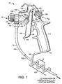
- a first illustrative embodiment of a modular coatings sprayer is a spray gun 20 configured for dispensing liquid coatings (e.g., paint) including a valve housing 30 and a valve-actuating assembly in the form of a trigger body 100.
- liquid coatings e.g., paint
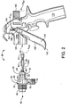
- the valve housing 30 and trigger body 100 are mutually coupleable and separable. As shown most clearly in FIG.
- the valve housing 30 in which the valve housing 30 is separated from the trigger body 100, the valve housing 30 has a front end 40 in which there is defined a nozzle orifice 42, a rear end 50 opposite the front end 40, a housing side wall 60 extending between the front and rear ends 40 and 50 and defining a central, internal fluid passage 70, and a fluid-supply opening 72 in the housing side wall 60.
- the fluid-supply opening 72 can be selectively coupled with, and decoupled from, a fluid-supply conduit 74, such as the coating-supply hose 74h in FIG. 1 , linked to a reservoir (not shown) of pressurized fluid coating material (e.g., paint) through a conduit coupling 76.
- a valve-shaft bore 52 for accommodating a valve shaft, as described below.
- the valve housing 30 supports a valve 80.
- the valve 80 includes an elongated valve shaft 82 with a back end 84 and a nozzle-closing front end 86 opposite the back end 84.
- the valve shaft 82 extends along a valve-shaft axis Avs through the valve-shaft bore 52 in the rear end 50 of the valve housing 30.
- the valve shaft 82 is sealably supported within the valve-shaft bore 52 for fluid-tight axial reciprocation with respect to the valve housing 30 such that the front end 86 is disposed within the fluid passage 70 and the back end 84 is situated rearwardly of the rear end 50 of the valve housing 30.
- the seal between the valve shaft 82 and the portion of the valve housing 30 defining the valve-shaft bore 52 may accomplished by a packing gland, a device known to those of ordinary skill in the art to which the present invention pertains and, therefore, not shown.
- the valve shaft 82 is normally biased toward a nozzle-closing position in which the nozzle-closing end 86 seals the nozzle orifice 42 such that fluid introduced through the fluid-supply opening 72 into the fluid passage 70 is prevented from exiting through the nozzle orifice 42.
- the valve shaft 82 is biased forwardly toward the nozzle-closing position by a biasing element 88 such as, by way of non-limiting example, a coiled spring 88cs retained within the valve housing 30 and helically disposed about a portion of the valve shaft 82.
- a biasing element 88 such as, by way of non-limiting example, a coiled spring 88cs retained within the valve housing 30 and helically disposed about a portion of the valve shaft 82.
- the nozzle-closing end 86 of the valve shaft 82 can be alternatively configured.
- the valve configuration is not of particular relevance to the present invention.
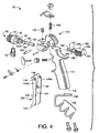
- the valve 80 shown in the cross-sectional view of FIG. 3 includes a valve shaft 82 that selectively urges an orifice-sealing element 89 (e.g. a ball) against the portion of the valve housing 30 defining the nozzle orifice 42 in order to close the orifice 42.
- an orifice-sealing element 89 e.g. a ball
- the trigger body 100 comprises a handle 110 configured for grasping by a human hand (not shown).
- a barrel 120 depends forwardly from the handle and includes a housing-retaining bore 122 that is configured for selectively receiving and retaining a rearward housing portion 54 that extends along a portion of the length of the valve housing 30 including the rear end 50 of the valve housing 30.
- the housing-retaining bore 122 and the rearward housing portion 54 are cylindrical in cross-section.
- the barrel 120 carries a catch 126 mechanically biased radially inwardly toward the housing-retaining bore 122 by a catch-spring 128.
- the catch 126 can be variously configured, the illustrative version depicted in the cross-sectional view of FIG.
- the outer surface 55 of the rearward housing portion 54 has defined therein a catch-receiving recess 56 for receiving the tip 129 of the spring-loaded catch 126.
- the recess 56 is an endless annular recess disposed about the outer surface 55 of the rearward housing portion 54. This latter feature obviates the need for a specific relative angular alignment between the valve housing 30 and the trigger body 100 as they are selectively coupled and, furthermore, permits rotation of the valve housing 30 with respect to the trigger body 100 when the rearward housing portion 54 is retained by the barrel 120.
- the trigger body 100 further includes a lever in the form of a trigger 140 situated forwardly of the handle 110.
- the trigger 140 includes a lower trigger end 142 and an upper trigger end 144 defining a yoke 146 with transversely spaced apart first and second yoke fingers 148a and 148b.
- the trigger 140 further includes a forward-facing finger-engaging trigger surface 150 and an opposed, rearward-facing valve-engaging surface 154.
- the surfaces 150 and 154 extend below the yoke fingers 148a and 148b to the lower trigger end 142 and transversely between the yoke fingers 148a and 148b. Defined through the finger-engaging and valve-engaging surfaces 150 and 154 is a valve-shaft notch 156 that communicates with, but is narrower than, the space between the yoke fingers 148a and 148b, and extends downwardly toward the lower trigger end 142.
- the trigger-pivot pin 160 is retained within an elongated pin slot 164 defined in the trigger body 100.
- the pin slot 164 enables selective lineal displacement of the pin 160 and trigger 140 in a direction including a component of spatial extension orthogonal to the valve-shaft axis A VS when the valve-housing 30 is cooperatively coupled with the trigger body 100.
- the pin 160 and trigger 140 are lineally displaceable between upper and lower trigger positions P TU and P TL as shown in, respectively, FIGS. 1 and 2 .
- the upper trigger position P TU is defined such that, when the valve housing 30 is cooperatively coupled with the trigger body 100 (i.e., the rearward housing portion 54 is retained by the barrel 120), the valve shaft 82 extends through the valve-shaft notch 156 such that the back end 84 of the valve shaft 82 is situated behind the valve-engaging surface 154.
- a portion of the length of the valve shaft 82 situated behind the trigger 140 is of enlarged cross section relative to the portion of the length of the valve shaft 82 passing through the valve-shaft notch 156.
- the enlarged valve-shaft portion 85 is sufficiently large along a least one transverse dimension orthogonal to the valve-shaft axis A VS that it defines a shaft shoulder 85S that cannot pass through the valve-shaft notch 156 in the trigger 140. Accordingly, as the trigger 140 is pivoted rearwardly toward the handle 110 by a user's fingers, the valve-engaging surface 154 can selectively engage the shaft shoulder 85S of the enlarged valve-shaft portion, and the valve shaft 82 can be pulled rearwardly by the trigger 140 in order to open the nozzle orifice 42.
- valve shaft 82 could comprise more than a single piece and that, for example, the enlarged valve-shaft portion 85 defining the shaft shoulder 85S could be comprised of a separate piece (e.g., a nut, sleeve or cap) threaded onto a thinner shaft component.
- a separate piece e.g., a nut, sleeve or cap
- the trigger 140 and pin 160 are displaced toward the lower trigger position P TL .
- the lower trigger position P TL is such that the enlarged valve-shaft portion 85 can clear the trigger 140. That is, the enlarged valve-shaft portion 85 can pass between the yoke fingers 148a and 148b unobstructed by trigger material defining the valve-shaft notch 156, thereby facilitating insertion and removal of the valve housing 30.
- the trigger 140 and pin 160 are retained in an upper trigger position P TU , such as the position shown in FIG. 1 .
- the trigger body 100 carriers a cam bolt 180 that is selectively displaceable between a first bolt position P B1 and a second bolt position P B2 as depicted in, respectively, FIGS. 1 and 2 .
- the cam bolt 180 includes opposed first end and second bolt ends 181 and 182. Extending along a portion of the length of the cam bolt 180 from the first end 181 is a bolt actuator 184 including gripping surfaces 185 configured for gripping by (e.g., squeezing between) a user's fingers (not shown). Situated between the bolt actuator 184 and the second bolt end 182 is a wedge-shaped portion 186 with a sloped pin-engaging surface 187.
- the wedge-shaped portion 186 interacts with the trigger-pivot pin 160 such that, as the cam bolt 180 is axially displaced toward the first bolt position P B1 , the trigger-pivot pin 160 rides along the sloped pin-engaging surface 187 and the pin 160 and trigger 140 are displaced toward the upper trigger position P TU . Conversely, as the cam bolt 180 is displaced toward the second bolt position P B1 , the pin 160 and trigger 140 are free to displace toward the lower trigger position P TL .
- the cam bolt 180 includes a pin cradle 188 in which the trigger-pivot pin 160 is seated when the pin 160 and trigger 140 are in an upper trigger position P TU . More specifically, as the cam bolt 180 is displaced toward the first bolt position P B1 , the trigger-pivot pin 160 rides along the sloped pin-engaging surface 187 until the pin 160 reaches an uppermost position.
- the pin cradle 188 is situated between the portion of the sloped pin-engaging surface 187 defining the uppermost trigger position and the bolt actuator 184 such that, as the cam bolt 180 is displaced all the way toward the first bolt position P B1 , the pin 160 sets into the pin cradle 188.
- each of various versions includes a pin-biasing element 162 that normally biases the trigger-pivot pin 160 toward a lower trigger position P TL .
- the pin-biasing element 162 acts to provide resistance against the movement of the trigger-pivot pin 160 from a seated position in the pin cradle 188.
- the pin-biasing element 162 provides a biasing force sufficiently large in magnitude to prevent the unintentional unseating of the pin 160 from the pin cradle 188 in normal use, but sufficiently small in magnitude that the pin 160 can be intentionally unseated by a user's gripping the gripping surfaces 185 and urging of the cam bolt 180 toward the second bolt position P B2 .
- various versions include a hose retainer 190 that depends downwardly from the butt end 112 of the handle 110.
- the hose retainer 190 shown in FIG. 1 comprises a rigid material such as metal wound to define a helical guide 192.
- Retainers similar to hose retainer 190 are known to those skilled in the relevant arts. However, such retainers have heretofore been too tightly wound to permit a hose of typical diameter to be removed from the helix, except axially through the helix.
- the pitch z of the helical guide 192 is defined such that a coating-supply hose 74h of a specified maximum outer hose diameter D OH can be removed from the helical guide 192 by "winding" it out of the helix.
- the pitch z is at least as large as the outer hose diameter D OH , but will usually be larger in order to account for factors that indicate a larger pitch z, such as, for example, the rigidity of the material from which the hose 74h is fabricated. Because the hose 74h can be freed from the helical guide 192 without disconnecting the valve housing 30 from the hose 74h , trigger body 100 can be readily coupled to another valve housing 30 linked, for example, to another color of paint or, the valve housing 30 that has been decoupled from the trigger body 100 can be readily coupled to another hand-held trigger body 100 or an alternative valve-actuating assembly such as the illustrative pole-mounted actuator head 300 discussed and described below in conjunction FIGS. 5 through 7 .
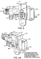
- the actuator head 300 shown in FIGS. 5 through 7 is configured for mounting to an extension pole (not shown) in order to facilitate reach to high places that are to be coated.
- the actuator head 300 includes a body in the form of a head housing 310 with front and rear ends 312 and 314 and left and right sides 316 and 318.
- the heading housing 310 further includes a pole mount 319 by which the head housing 310 can be secured to the distal end of an extension pole that includes a trigger at a proximal pole end opposite the distal end.
- An illustrative extension pole is not shown because illustration of the same is not necessary to the comprehension of the invention by one of ordinary skill in the art to which the invention pertains.
- the mechanisms by which the pole mount 319 is secured to the distal end of an extension pole are such that the heading housing 310 can pivot with respect to the extension pole.
- a barrel 320 defined within the head housing 310 includes a housing-retaining bore 322 that is open to the front end 312 of the head housing 310 and is configured for selectively receiving and retaining the rearward housing portion 54 previously described in connection with the illustrative trigger body 100.
- the housing-retaining bore 322 and the rearward housing portion 54 are cylindrical in cross-section.
- the barrel 320 carries a catch 326 analogous to the catch 126 discussed in association with trigger body 100.
- the catch 326 is mechanically biased radially inwardly toward the housing-retaining bore 322 by a catch-spring 328.
- the catch 326 can be variously configured, the illustrative version depicted in the cross-sectional view of FIG.
- the outer surface 55 of the rearward housing portion 54 has defined therein a catch-receiving recess 56.
- the catch-receiving recess 56 is configured for receiving the tip 329 of the spring-loaded catch 326 in a manner similar to which the recess 56 is shown to have received tip 129 of the spring-loaded catch 126 in FIG. 3 .
- the recess 56 is an endless annular recess disposed about the outer surface 55 of the rearward housing portion 54, as in FIGS. 3 and 6 , there is no need for a specific relative angular alignment between the valve housing 30 and the actuator head 300 as they are selectively coupled.
- an endless annular recess 56 permits rotation of the valve housing 30 with respect to the actuator head 300 when the rearward housing portion 54 is retained within the barrel 320.
- the actuator head 300 further includes a valve-shaft lever 340.
- the valve-shaft lever 340 is mounted within the head housing 310 for pivotable displacement, relative to the head housing 310, between a forward position (shown in FIG. 6 ) and a backward position (indicated by arrow in FIG. 6 ).
- the lever 340 is retained by a lever carriage which, in the illustrative version depicted in FIGS. 6 and 7 , is in the form of a lever casing 350.
- a lever carriage which, in the illustrative version depicted in FIGS. 6 and 7 , is in the form of a lever casing 350.
- the lever carriage i.e., casing 350
- the lever 340 is itself pivotably mounted via a lever-pivot pin 360 within and to the head housing 310, thereby rendering the valve-shaft lever 340 pivotably mounted within the head housing 310.
- the lever 340 further includes a lever wall 341 having defined through a portion thereof a keyed valve-shaft opening 342 with a first opening portion 342a and a second opening portion 342b larger (e.g., wider) than the first opening portion 342a.
- the lever wall 341 further includes a rearward-facing valve-engaging surface 344, the purpose of which is explained in greater detail below.
- valve shaft 82 when the valve-housing 30 is cooperatively coupled with the actuator head 300, the valve shaft 82 extends through the keyed valve-shaft opening 342, and front and back valve-shaft openings (not labeled) in the casing 350, such that the back end 84 of the valve shaft 82 is situated behind the valve-engaging surface 344.
- a portion of the length of the valve shaft 82 situated behind the valve-engaging surface 344 is of enlarged cross section relative to the portion of the length of the valve shaft 82 passing through the keyed valve-shaft opening 342.
- the enlarged valve-shaft portion 85 is sufficiently large along at least one dimension orthogonal to the valve-shaft axis A VS that it defines a shoulder 85S that cannot pass through the smaller, first opening portion 342a of the keyed valve-shaft opening 342.
- the forward position of the lever 340 is such that the valve-shaft 82 (see FIG. 3 ) is in a nozzle-closing position in which the nozzle-closing end 86 seals the nozzle orifice 42 in the front end 40 of the valve housing 30.
- the valve-engaging surface 344 engages the shaft shoulder 85S of the enlarged valve-shaft portion, and the valve shaft 82 is displaced rearwardly by the lever 340 in order to open the nozzle orifice 42.
- the lever 340 In order to enable displacement of the lever 340 toward the backward position by remotely situated mechanisms including, for instance, a trigger located near the proximal end of an extension pole, the lever 340 is linked to an elongated flexible linkage 400.
- the lever 340 In the version of FIGS. 6 and 7 , the lever 340 is not directly coupled to flexible linkage 400; instead, the casing 350 in which the lever 340 is retained is coupled to flexible linkage 400.
- the lever 340 can be lineally displaced in a direction having a component of spatial extension orthogonal to the valve-shaft axis Avs in order to accommodate passage of the enlarged valve-shaft portion 85 through the larger, second opening portion 342b of the keyed valve-shaft opening 342. More specifically, the lever 340 is carried by the lever carriage 350 such that it can be lineally displaced, with respect to the carriage 350, between opposed first and second lineal positions. In FIG. 6 , the lever 340 is shown in a first lineal position.
- a first lineal position is defined such that the first opening portion 342a in the lever 340 is sufficiently aligned with the shaft shoulder 85S that the valve shaft 82 cannot be axially displaced through the valve-shaft opening 342 in the lever 340 and, consequently, such that, as the lever 340 is pivoted toward the backward position, the valve-engaging surface 344 engages the shaft shoulder 85S, and the valve shaft 82 is displaced rearwardly in order to open the nozzle orifice 42.
- a second lineal position is defined such that the shaft shoulder 85S can be axially displaced through the larger, second opening portion 342b of the keyed valve-shaft opening 342; thereby facilitating selective removal from, or insertion into, the actuator head 300 of the valve housing 30.
- the lever 340 is normally biased toward both the forward pivot position and the first lineal position.
- the illustrative version of FIGS. 6 and 7 includes a single lever-biasing element 370 that serves both biasing functions.
- the lever-biasing element 370 is in the form of a coiled spring 372 coupled to the housing head 310 and lever 340 so as to provide a contractive restorative force toward the first lineal position (downward, in this case) when the lever 340 is urged, by an external force, toward the second lineal position (upward, in this case).
- the spring 372 is furthermore aligned with respect to the lever 340 such that the helical portion thereof is more "on-axis" when the lever 340 is in the forward pivot position than when the lever 340 is in the backward pivot position. It will be appreciated that the tendency of the coiled spring 372 toward an attitude in which the helix thereof extends along a straight axis biases the lever 340 toward the forward pivot position. It will also be appreciated that the biasing functions described above can be provided by alternative, and even separate, biasing elements 370 and the example of a single coiled spring 372 is illustrative in nature and in no way limits the invention as defined in the appended claims.
- a post 352 mechanically links the lever 340 to the exterior of the housing head 310 so that a user can manually displace the lever 340.
- the post depends from the lever 340 and extends laterally through a post opening 355 in one side of the housing head 310.
- the end of the post 350 extending to the exterior of the housing head 310 is a lever button 357 including a fingering-engaging surface 358.
Landscapes
- Nozzles (AREA)
Claims (9)
- Modulares Beschichtungssprühgerät (20), das zum Auftragen unter Druck stehender flüssiger Beschichtungen auf eine Oberfläche konfiguriert ist und umfassend:ein Ventilgehäuse (30) mit einem a) vorderen Ende (40), in dem eine Düsenöffnung (42) definiert ist, b) einem hinteren Ende (50) gegenüber dem vorderen Ende und durch welches eine Ventilschaftbohrung (52) zum Abstützen eines Ventilschafts definiert ist, c) eine Gehäuseseitenwand (60), die sich zwischen den vorderen (40) und hinteren (50) Enden erstreckt und einen inneren Flüssigkeitsdurchgang (70) definiert, und d) eine Fluidzufuhröffnung (72) in der Gehäuseseitenwand (60) durch welche unter Druck stehendes Fluid in den inneren Fluiddurchgang (70) eingeführt werden kann;ein Ventil mit einem lang gezogenen Ventilschaft (82) mit einem hinteren Ende (84) und einem Düsenverschluss-Vorderende (86) gegenüber dem hinteren Ende, wobei i) sich der Ventilschaft (82) entlang einer Ventilschaftachse erstreckt und abdichtbar innerhalb der Ventilschaftbohrung (52) zwecks fluiddichter axialer Hin- und Herbewegung relativ zum Ventilgehäuse (30) abgestützt ist, ii) sich das Düsenverschlussende (86) beim inneren Fluiddurchgang (70) befindet und sich das hintere Ende (84) rückwärtig des hinteren Endes (50) des Ventilgehäuses (30) befindet, und iii) der Ventilschaft (82) normalerweise in Richtung einer vorderen, Düsenverschlussposition vorgespannt ist, in welcher das Düsenverschlussende (86) die Düsenöffnung (42) so abdichtet, dass unter Druck stehendes durch die Fluidzufuhröffnung (72) in den Fluiddurchgang (70) eingeführtes Fluid daran gehindert wird durch die Düsenöffnung (42) auszutreten;dadurch gekennzeichnet, dass es weiter umfasst:eine Ventilbetätigungsanordnung, die zur selektiven kooperativen Kupplung an das und zur Trennung vom Ventilgehäuse (30) konfiguriert ist, und umfasst:einen Körper; undeinen relativ zum Körper montierten Hebel für drehgelenkige Bewegung und eindimensionale Verschiebung zwischen operativen und nicht operativen eindimensionalen Positionen, und einschließlich einer Ventilkupplungsoberfläche (154) die, wenn in einer operativen Position befindlich, selektiv einen Abschnitt des Ventilschafts extern zum Ventilgehäuse (30) derart kuppelt, dass i) wenn der Hebel drehgelenkig in eine erste Richtung bewegt wird, der Ventilschaft (82) nach rückwärts verschoben wird, um die Düsenöffnung (42) zu öffnen, und ii) wenn der Hebel drehgelenkig in eine zweite Richtung, entgegengesetzt zur ersten Richtung, bewegt wird, der Ventilschaft (82) vorwärts in Richtung der Düsenverschlussposition verschoben wird.
- Modulares Beschichtungssprühgerät (20) nach Anspruch 1, wobei a) die Ventilbetätigungsanordnung einen Triggerkörper (100) mit i) einem Griff (110), der konfiguriert ist, von einer menschlichen Hand ergriffen zu werden und ii) einen Zylinder (120) umfasst, der sich vorwärts des Griffs (110) erstreckt und konfiguriert ist, selektiv einen Abschnitt der Länge des Ventilgehäuses (30) aufzunehmen und beizubehalten, und b) der Hebel ein Trigger (140) ist, der vorwärts des Griffs angeordnet ist und von einem Trigger-Drehzapfen (160) für drehgelenkige Bewegung und eindimensionale Verschiebung relativ zum Griffe (110) gehalten wird.
- Modulares Beschichtungssprühgerät (20) nach Anspruch 2, wobei i) die Fluidzufuhröffnung (72) selektiv mit einer Fluidzufuhrleitung (74) gekoppelt und von dieser entkoppelt werden kann, die mit einem Reservoir von unter Druck stehendem Fluidbeschichtungsmaterial verbunden ist und ii) wenn die Fluidzufuhröffnung (72) an das Reservoir unter Druck stehendem Material gekoppelt ist, der Triggerkörper (100) und das Ventilgehäuse (30) gegenseitig gekoppelt und entkoppelt werden können, ohne Druck in der Fluidverbindung zwischen dem Reservoir und dem inneren Fluiddurchgang (70), der innerhalb des Ventilgehäuses (30) definiert ist, abbauen zu müssen.
- Modulares Beschichtungssprühgerät (20) nach Anspruch 3, wobeia) der Trigger (140) einschließt: i) ein unteres Triggerende (142), ii) ein oberes Triggerende (144), das eine Gabel (146) mit quer beabstandeten ersten (148a) und zweiten (148b) Gabelfingern definiert, durch die der Trigger-Drehzapfen (160) hindurch geht, um den Trigger (140) zu halten, iii) eine Finger kuppelnde Fläche (150), die sich quer zwischen den Fingern erstreckt und eine Ventilschaftkerbe (156) einschließt, die sich in Richtung des unteren Triggerendes (142) erstreckt und enger als der Abstand zwischen den Gabelfingern ist, und iv) eine Ventilkupplungsfläche (154) gegenüber der Finger kuppelnden Fläche (150);b) der Trigger-Drehzapfen (160) wird innerhalb eines lang gestreckten Zapfenschlitzes (164) gehalten, der im Triggerkörper definiert ist, um selektive eindimensionale Verschiebung des Zapfens (160) und des Triggers (140) zwischen oberen und unteren Triggerpositionen zu erleichtern;c) der Ventilschaft (82) schließt einen vergrößerten Ventilschaftabschnitt (85), der ausreichend groß entlang wenigstens einer Abmessung ist, dass sie eine Schaftschulter (85S) definiert, die nicht durch die Ventilschaftkerbe (156) hindurch gehen kann;d) die obere Triggerposition ist eine operative Position derart, dass i) wenn das Ventilgehäuse (30) und der Triggerkörper (100) kooperativ gekoppelt sind, ein Abschnitt der Länge des Ventilschafts (82) durch die Ventilschaftkerbe (156) hindurch geht und sich der vergrößerte Ventilschaftabschnitt (85) hinter dem Trigger (140) befindet, und ii) nach rückwärts Schwenken des Triggers (140) in Richtung des Griffs (110) die Ventil koppelnde Fläche (154) veranlasst die Schaftschulter (85S) in Eingriff zu bringen und den Ventilschaft (82) zu verschieben, um die Düsenöffnung (42) zu öffnen; unde) die untere Triggerposition eine nicht operative Position derart ist, dass der vergrößerte Schaftabschnitt (85) zwischen den Gabelfingern hindurch gehen kann, um dadurch das alternative Einfügen in den und Entfernen des Ventilgehäuses (30) aus dem Triggerkörper (100) zu erleichtern.
- Modulares Beschichtungssprühgerät (20) nach Anspruch 1, wobei i) die Fluidzufuhröffnung (72) selektiv mit einer Fluidzufuhrleitung (74) gekoppelt und von dieser entkoppelt werden kann, die mit einem Reservoir von unter Druck stehendem Fluidbeschichtungsmaterial verbunden ist und ii) wenn die Fluidzufuhröffnung (72) an das Reservoir unter Druck stehendem Material gekoppelt ist, die Ventilbetätigungsanordnung und das Ventilgehäuse (30) gegenseitig gekoppelt und entkoppelt werden können, ohne Druck in der Fluidverbindung zwischen dem Reservoir und dem inneren Fluiddurchgang (70), der innerhalb des Ventilgehäuses (30) definiert ist, abbauen zu müssen.
- Modulares Beschichtungssprühgerät (20) nach Anspruch 1, wobei die Ventilbetätigungsanordnung, an welche das Ventilgehäuse (30) selektiv koppelbar ist, ein an einer Stange montierter Betätigungskopf (300) ist, der ein Kopfgehäuse (310) einschließt, das umfasst:Vordere (312) und hintere (314) Enden;Eine Stangenhalterung (319) mittels der sich das Kopfgehäuse (310) am distalen Ende einer Verlängerungsstange befestigen lässt, die, zusätzlich zum distalen Ende, ein proximales Ende gegenüber dem distalen Ende und einen Trigger näher am proximalen Ende als am distalen Ende aufweist; undeinen Zylinder (320) der einen Gehäusehaltekanal (322) einschließt, der zum vorderen Ende (312) offen und für selektives Empfangen und Halten eines Abschnitts der Länge des Ventilgehäuses (30) konfiguriert ist; wobeii) der Hebel ein Ventilschafthebel (340) ist, der innerhalb des Kopfgehäuses (310) für drehgelenkige Verschiebung, relativ zum Kopfgehäuse, zwischen einer vordersten Position und einer hinteren Position montiert ist;ii) die vorderste Position des Ventilschafthebels (340) entspricht der Düsenverschlussposition des Ventilschafts (82); undiii) der Ventilschafthebel (340) ist mit einer lang gestreckten flexiblen Verbindung (400) verbunden, die Verschiebung des Ventilschafthebels in Richtung einer rückwärtigen Position und die entsprechende rückwärtige Verschiebung des Ventilschafts (82) ermöglicht, um die Düsenöffnung (42) zu öffnen.
- Modulares Beschichtungssprühgerät (20) nach Anspruch 6, wobeia) der Ventilschafthebel (340) eine Hebelwand (341) einschließt, die i) eine rückwärts gewandte Ventilkupplungsfläche (344) und ii) definiert durch einen Abschnitt davon, eine mit Nut und Feder versehene Ventilschaftöffnung (342) mit einen ersten Öffnungsabschnitt (342a) und einen zweiten Öffnungsabschnitt (342b) aufweist, der entlang wenigstens einer Abmessung größer als der erste Öffnungsabschnitt (342a) ist;b) zusätzlich dazu, dass der Ventilschafthebel (340) relativ zum Kopfgehäuse (310) drehgelenkig verschiebbar ist, ist dieser zur selektiven eindimensionalen Verschiebung, relativ zum Kopfgehäuse, zwischen ersten und zweiten eindimensionalen Positionen montiert;c) der Ventilschaft (82) einen vergrößerten Ventilschaftabschnitt (85) einschließt, der ausreichend groß entlang wenigstens einer Abmessung ist, dass sie eine Schaftschulter (85S) definiert, die nicht durch den ersten Öffnungsabschnitt (342a) hindurch gehen kann;d) die obere Triggerposition eine operative Position derart ist, dass i) wenn das Ventilgehäuse (30) und der Triggerkörper (300) kooperativ gekoppelt sind, ein Abschnitt der Länge des Ventilschafts (82) durch die mit Nut und Feder versehene Ventilschaftöffnung (342) hindurch geht und sich der vergrößerte Ventilschaftabschnitt (85) hinter dem Ventilschafthebel (340) befindet, und ii) nach rückwärts Schwenken des Ventilschafthebels (340) die Ventil koppelnde Fläche (154) veranlasst, die Schaftschulter (85S) in Eingriff zu bringen und den Ventilschaft zu verschieben, um die Düsenöffnung (42) zu öffnen; unde) die zweite eindimensionale Position nicht operativ ist, derart, dass der vergrößerte Schaftabschnitt (85) durch den zweiten Öffnungsabschnitt (342b) hindurch gehen kann, um dadurch das alternative Koppeln und Entkoppeln des Ventilgehäuses (30) und des Betätigungskopfes (300) zu erleichtern.
- Modulares Beschichtungssprühgerät (20) nach Anspruch 7, wobei i) die Fluidzufuhröffnung (72) selektiv mit einer Fluidzufuhrleitung (74) gekoppelt und von dieser entkoppelt werden kann, die mit einem Reservoir von unter Druck stehendem Fluidbeschichtungsmaterial verbunden ist und ii) wenn die Fluidzufuhröffnung an ein Reservoir von unter Druck stehendem Material gekoppelt ist, der Betätigungskopf (300) und das Ventilgehäuse (30) gegenseitig gekoppelt und entkoppelt werden können, ohne Druck in der Fluidverbindung zwischen dem Reservoir und dem inneren Fluiddurchgang (70), der innerhalb des Ventilgehäuses (30) definiert ist, abbauen zu müssen.
- Modulares Beschichtungssprühgerät (20) nach Anspruch 6, wobei i) die Fluidzufuhröffnung (72) selektiv mit einer Fluidzufuhrleitung (74) gekoppelt und von dieser entkoppelt werden kann, die mit einem Reservoir von unter Druck stehendem Fluidbeschichtungsmaterial verbunden ist und ii) wenn die Fluidzufuhröffnung an ein Reservoir von unter Druck stehendem Material gekoppelt ist, der Betätigungskopf (300) und das Ventilgehäuse (30) gegenseitig gekoppelt und entkoppelt werden können, ohne Druck in der Fluidverbindung zwischen dem Reservoir und dem inneren Fluiddurchgang (70), der innerhalb des Ventilgehäuses (30) definiert ist, abbauen zu müssen.
Applications Claiming Priority (3)
| Application Number | Priority Date | Filing Date | Title |
|---|---|---|---|
| US18913208P | 2008-08-15 | 2008-08-15 | |
| US12/583,187 US8439281B2 (en) | 2008-08-15 | 2009-08-14 | Modular coatings sprayer |
| PCT/US2009/004687 WO2010019274A1 (en) | 2008-08-15 | 2009-08-17 | Modular coatings sprayer |
Publications (3)
| Publication Number | Publication Date |
|---|---|
| EP2344280A1 EP2344280A1 (de) | 2011-07-20 |
| EP2344280A4 EP2344280A4 (de) | 2014-04-23 |
| EP2344280B1 true EP2344280B1 (de) | 2016-01-27 |
Family
ID=41669157
Family Applications (1)
| Application Number | Title | Priority Date | Filing Date |
|---|---|---|---|
| EP09806989.1A Not-in-force EP2344280B1 (de) | 2008-08-15 | 2009-08-17 | Modulares beschichtungssprühgerät |
Country Status (7)
| Country | Link |
|---|---|
| US (1) | US8439281B2 (de) |
| EP (1) | EP2344280B1 (de) |
| JP (1) | JP5490798B2 (de) |
| CN (1) | CN102186597B (de) |
| AU (1) | AU2009282454B2 (de) |
| CA (1) | CA2734232C (de) |
| WO (1) | WO2010019274A1 (de) |
Cited By (2)
| Publication number | Priority date | Publication date | Assignee | Title |
|---|---|---|---|---|
| US10328447B1 (en) | 2018-01-30 | 2019-06-25 | The Procter & Gamble Company | Spray dispenser for liquid dispensing product having a nozzle guard |
| US11498089B2 (en) | 2021-04-04 | 2022-11-15 | Armin Arminak | All plastic continuous spray trigger sprayer |
Families Citing this family (46)
| Publication number | Priority date | Publication date | Assignee | Title |
|---|---|---|---|---|
| US7914726B2 (en) * | 2006-04-13 | 2011-03-29 | Amcor Limited | Liquid or hydraulic blow molding |
| US8573964B2 (en) * | 2006-04-13 | 2013-11-05 | Amcor Limited | Liquid or hydraulic blow molding |
| DE502007000825D1 (de) | 2006-12-05 | 2009-07-16 | Sata Gmbh & Co Kg | Belüftung für den Fließbecher einer Farbspritzpistole |
| US8017064B2 (en) * | 2007-12-06 | 2011-09-13 | Amcor Limited | Liquid or hydraulic blow molding |
| JP2011519307A (ja) | 2008-03-12 | 2011-07-07 | ジェフリー ディー フォックス | 使い捨てスプレーガンカートリッジ |
| CN102215981B (zh) * | 2008-12-18 | 2014-04-16 | 格雷索明尼苏达有限公司 | 无工具换针喷枪 |
| DE102009032399A1 (de) | 2009-07-08 | 2011-01-13 | Sata Gmbh & Co. Kg | Farbspritzpistole |
| DE202010007355U1 (de) | 2010-05-28 | 2011-10-20 | Sata Gmbh & Co. Kg | Düsenkopf für eine Spritzvorrichtung |
| US8828308B2 (en) | 2010-09-13 | 2014-09-09 | Amcor Limited | Hydroblow preform design |
| US8721315B2 (en) | 2010-09-13 | 2014-05-13 | Amcor Limited | Method of handling liquid to prevent machine contamination during filling |
| US8834778B2 (en) | 2010-09-13 | 2014-09-16 | Amcor Limited | Mold delay for increased pressure for forming container |
| US9314955B2 (en) | 2010-10-15 | 2016-04-19 | Discma Ag | Use of optimized piston member for generating peak liquid pressure |
| US8714964B2 (en) | 2010-10-15 | 2014-05-06 | Amcor Limited | Blow nozzle to control liquid flow with pre-stretch rod assembly |
| US8968636B2 (en) | 2010-10-15 | 2015-03-03 | Discma Ag | Stretch rod system for liquid or hydraulic blow molding |
| US9333519B2 (en) | 2010-12-02 | 2016-05-10 | Sata Gmbh & Co. Kg | Spray gun and accessories |
| WO2012112474A2 (en) | 2011-02-15 | 2012-08-23 | Amcor Limited | Reverse stretch rod for machine hygiene and processing |
| MX2013009215A (es) * | 2011-02-16 | 2014-06-23 | Amcor Ltd | Boquilla de soplado para control de flujo de liquido con montaje de varilla de pre-estirado y pasador para sello de asiento de metal. |
| US9044887B2 (en) | 2011-05-27 | 2015-06-02 | Discma Ag | Method of forming a container |
| EP2694271B1 (de) | 2011-06-09 | 2015-10-21 | Discma AG | System |
| EP2697121B1 (de) | 2011-06-09 | 2016-12-07 | Discma AG | Csd-kühlung und druckbeaufschlagung zur aufrechterhaltung des co2-anteils in einer lösung während ihrer herstellung |
| CN103517765B (zh) * | 2011-06-30 | 2017-09-12 | 萨塔有限两合公司 | 易清洗的喷枪、用于喷枪的附件及安装和拆卸方法 |
| US9254617B2 (en) | 2011-10-27 | 2016-02-09 | Discma Ag | Method and apparatus for forming and filling a container |
| WO2013063461A1 (en) | 2011-10-27 | 2013-05-02 | Amcor Limited | Counter stretch connecting rod and positive fill level control rod |
| US8827688B2 (en) | 2011-12-21 | 2014-09-09 | Amcor Limited | Sealing system for molding machine |
| JP6266532B2 (ja) | 2011-12-22 | 2018-01-24 | アムコー リミテッド | 容器の壁の厚みにおける温度勾配を制御する方法および装置 |
| CA155474S (en) | 2013-09-27 | 2015-08-27 | Sata Gmbh & Co Kg | Spray gun |
| DE202013105779U1 (de) | 2013-12-18 | 2015-03-19 | Sata Gmbh & Co. Kg | Luftdüsenabschluss für eine Lackierpistole |
| CA159961S (en) | 2014-07-31 | 2015-07-17 | Sata Gmbh & Co Kg | Spray gun |
| CN105289870B (zh) | 2014-07-31 | 2019-09-24 | 萨塔有限两合公司 | 喷枪的制造方法、喷枪、喷枪本体以及盖 |
| USD758537S1 (en) | 2014-07-31 | 2016-06-07 | Sata Gmbh & Co. Kg | Paint spray gun rear portion |
| USD768820S1 (en) | 2014-09-03 | 2016-10-11 | Sata Gmbh & Co. Kg | Paint spray gun with pattern |
| WO2016162063A1 (en) * | 2015-04-09 | 2016-10-13 | Husqvarna Ab | Modular spraying apparatus and corresponding assembling method |
| US10987687B2 (en) | 2015-04-20 | 2021-04-27 | Wagner Spray Tech Corporation | Adjustable handle for a liquid applicator |
| DE102015006484A1 (de) | 2015-05-22 | 2016-11-24 | Sata Gmbh & Co. Kg | Düsenanordnung für eine Spritzpistole, insbesondere Farbspritzpistole und Spritzpistole, insbesondere Farbspritzpistole |
| CN107683179B (zh) * | 2015-06-19 | 2020-06-19 | 固瑞克明尼苏达有限公司 | 用于无气喷枪的压力供给附件适配器 |
| DE102015016474A1 (de) | 2015-12-21 | 2017-06-22 | Sata Gmbh & Co. Kg | Luftkappe und Düsenanordnung für eine Spritzpistole und Spritzpistole |
| CN205995666U (zh) | 2016-08-19 | 2017-03-08 | 萨塔有限两合公司 | 喷枪及其扳机 |
| CN205966208U (zh) | 2016-08-19 | 2017-02-22 | 萨塔有限两合公司 | 风帽组件以及喷枪 |
| US10589303B2 (en) | 2018-04-01 | 2020-03-17 | Graco Minnesota Inc. | Spray gun and components for spraying paints and other coatings |
| US20190321838A1 (en) * | 2018-04-19 | 2019-10-24 | Schieffer Co. International L.C. | Spray gun |
| DE102018118738A1 (de) | 2018-08-01 | 2020-02-06 | Sata Gmbh & Co. Kg | Grundkörper für eine Spritzpistole, Spritzpistolen, Spritzpistolen-Set, Verfahren zur Herstellung eines Grundkörpers für eine Spritzpistole und Verfahren zum Umrüsten einer Spritzpistole |
| DE102018118737A1 (de) | 2018-08-01 | 2020-02-06 | Sata Gmbh & Co. Kg | Düse für eine Spritzpistole, Düsensatz für eine Spritzpistole, Spritzpistolen und Verfahren zur Herstellung einer Düse für eine Spritzpistole |
| CN112533705B (zh) | 2018-08-01 | 2023-07-04 | 萨塔有限两合公司 | 喷枪的喷嘴组、喷枪系统、制造喷嘴模块的方法、为上漆任务从喷嘴组选出喷嘴模块的方法、选择系统和计算机程序产品 |
| DE102020123769A1 (de) | 2020-09-11 | 2022-03-17 | Sata Gmbh & Co. Kg | Dichtelement zum Abdichten eines Übergangs zwischen einem Grundkörper einer Spritzpistole und einem Anbauteil einer Spritzpistole, Anbauteil, insbesondere Farbdüsenanordnung, für eine Spritzpistole und Spritzpistole, insbesondere Farbspritzpistole |
| USD963796S1 (en) * | 2020-09-16 | 2022-09-13 | Graco Minnesota Inc. | Fan air lever for a spray gun |
| WO2022261435A1 (en) * | 2021-06-10 | 2022-12-15 | Graco Minnesota Inc. | Spray gun and components for spraying paints and other coatings |
Family Cites Families (21)
| Publication number | Priority date | Publication date | Assignee | Title |
|---|---|---|---|---|
| US2705663A (en) * | 1952-08-08 | 1955-04-05 | Robert I Gilbreath | Spray gun |
| US2991940A (en) * | 1957-07-11 | 1961-07-11 | Gen Motors Corp | Paint spray gun with detachable head |
| US3410491A (en) * | 1966-08-26 | 1968-11-12 | Tri Matic Equipment Co | Valve means |
| DE2230148C3 (de) | 1972-06-21 | 1979-03-08 | Guenther 5400 Koblenz Schneider | Gestänge zum Fuhren einer Spritzpistole |
| US4013225A (en) * | 1974-04-29 | 1977-03-22 | Davis J C | Extension spray gun |
| US4457472A (en) * | 1982-11-08 | 1984-07-03 | Geberth John Daniel Jun | Extendable spray gun |
| DE3926461A1 (de) * | 1989-07-15 | 1991-01-24 | Suttner Gmbh & Co Kg | Ventilpistole, insbesondere fuer ein hochdruckreinigungsgeraet |
| JPH0734880B2 (ja) * | 1992-02-03 | 1995-04-19 | 有限会社ミナリ | 塗装ガン |
| US5370315A (en) * | 1993-10-15 | 1994-12-06 | Del Gaone; Peter V. | Spray gun for aggregates |
| US5772116A (en) * | 1993-12-02 | 1998-06-30 | Holt; Earl R. | Recirculating paint system having an improved spray gun |
| US6460787B1 (en) | 1998-10-22 | 2002-10-08 | Nordson Corporation | Modular fluid spray gun |
| US6276616B1 (en) * | 2000-04-07 | 2001-08-21 | Illinois Tool Works Inc. | Fluid needle loading assembly for an airless spray paint gun |
| DE10208861B4 (de) * | 2002-03-01 | 2015-07-23 | J. Wagner Gmbh | Spritzpistole |
| US6874702B2 (en) * | 2002-10-08 | 2005-04-05 | Micron Technology, Inc. | Modular spray gun apparatus and methods |
| CN1859951B (zh) * | 2003-10-22 | 2010-09-01 | 贸易联合公司 | 模块化的喷枪装置和方法 |
| CN2657788Y (zh) * | 2003-11-17 | 2004-11-24 | 王俊霖 | 一种模块化喷射气雾器 |
| US7032839B2 (en) * | 2003-12-30 | 2006-04-25 | 3M Innovative Properties Company | Liquid spray gun with manually separable portions |
| US7364098B2 (en) * | 2005-10-12 | 2008-04-29 | Illinois Tool Works Inc. | Material dispensing apparatus |
| ATE510627T1 (de) * | 2007-04-11 | 2011-06-15 | Bernd Kriesmair | Vorrichtung zum aufsprühen von pigmentierten flüssigkeiten |
| US7922107B2 (en) * | 2007-07-25 | 2011-04-12 | Fox Jeffrey D | Spray gun with paint cartridge |
| JP2011519307A (ja) * | 2008-03-12 | 2011-07-07 | ジェフリー ディー フォックス | 使い捨てスプレーガンカートリッジ |
-
2009
- 2009-08-14 US US12/583,187 patent/US8439281B2/en active Active
- 2009-08-17 AU AU2009282454A patent/AU2009282454B2/en not_active Ceased
- 2009-08-17 EP EP09806989.1A patent/EP2344280B1/de not_active Not-in-force
- 2009-08-17 WO PCT/US2009/004687 patent/WO2010019274A1/en active Application Filing
- 2009-08-17 JP JP2011523007A patent/JP5490798B2/ja not_active Expired - Fee Related
- 2009-08-17 CA CA2734232A patent/CA2734232C/en active Active
- 2009-08-17 CN CN200980141038.8A patent/CN102186597B/zh active Active
Cited By (2)
| Publication number | Priority date | Publication date | Assignee | Title |
|---|---|---|---|---|
| US10328447B1 (en) | 2018-01-30 | 2019-06-25 | The Procter & Gamble Company | Spray dispenser for liquid dispensing product having a nozzle guard |
| US11498089B2 (en) | 2021-04-04 | 2022-11-15 | Armin Arminak | All plastic continuous spray trigger sprayer |
Also Published As
| Publication number | Publication date |
|---|---|
| AU2009282454B2 (en) | 2014-04-10 |
| EP2344280A1 (de) | 2011-07-20 |
| JP2012500107A (ja) | 2012-01-05 |
| US20100084493A1 (en) | 2010-04-08 |
| CN102186597A (zh) | 2011-09-14 |
| WO2010019274A1 (en) | 2010-02-18 |
| AU2009282454A1 (en) | 2010-02-18 |
| CA2734232C (en) | 2015-12-08 |
| CA2734232A1 (en) | 2010-02-18 |
| CN102186597B (zh) | 2014-09-24 |
| JP5490798B2 (ja) | 2014-05-14 |
| EP2344280A4 (de) | 2014-04-23 |
| US8439281B2 (en) | 2013-05-14 |
Similar Documents
| Publication | Publication Date | Title |
|---|---|---|
| EP2344280B1 (de) | Modulares beschichtungssprühgerät | |
| EP2265387B1 (de) | Wegwerf-spritzpistolenkartusche | |
| US7455198B2 (en) | Trigger forward pivot limit for a trigger sprayer | |
| TW201941833A (zh) | 用於噴塗油漆及其他塗層之噴槍及元件 | |
| EP3784412B1 (de) | Flache luftlose spritzpistole zum auftragen von lack | |
| EP2055390B1 (de) | Sprühpistole | |
| US5829681A (en) | Spray gun with double trigger levers for dispensing two liquids independently or in admixture | |
| CN107683179B (zh) | 用于无气喷枪的压力供给附件适配器 | |
| US11772117B2 (en) | Spray gun for spraying paints and other coatings | |
| EP3556471A1 (de) | Spritzpistole | |
| US5143299A (en) | Spray gun | |
| CN108339683B (zh) | Hvlp喷帽组件的保持和拆卸 | |
| US11603256B2 (en) | Device to spray omnidirectionally and avoid backflow | |
| US6619569B2 (en) | Extended reach pressure relief spray valve | |
| CN118510609A (zh) | 带有适配器和多种压力模式的泡沫喷洒器 |
Legal Events
| Date | Code | Title | Description |
|---|---|---|---|
| PUAI | Public reference made under article 153(3) epc to a published international application that has entered the european phase |
Free format text: ORIGINAL CODE: 0009012 |
|
| 17P | Request for examination filed |
Effective date: 20110315 |
|
| AK | Designated contracting states |
Kind code of ref document: A1 Designated state(s): AT BE BG CH CY CZ DE DK EE ES FI FR GB GR HR HU IE IS IT LI LT LU LV MC MK MT NL NO PL PT RO SE SI SK SM TR |
|
| AX | Request for extension of the european patent |
Extension state: AL BA RS |
|
| DAX | Request for extension of the european patent (deleted) | ||
| A4 | Supplementary search report drawn up and despatched |
Effective date: 20140324 |
|
| RIC1 | Information provided on ipc code assigned before grant |
Ipc: B05B 9/01 20060101AFI20140318BHEP Ipc: B05B 1/30 20060101ALI20140318BHEP Ipc: B05B 15/06 20060101ALI20140318BHEP Ipc: B05B 15/00 20060101ALI20140318BHEP Ipc: B05B 12/00 20060101ALI20140318BHEP |
|
| GRAP | Despatch of communication of intention to grant a patent |
Free format text: ORIGINAL CODE: EPIDOSNIGR1 |
|
| INTG | Intention to grant announced |
Effective date: 20150720 |
|
| GRAS | Grant fee paid |
Free format text: ORIGINAL CODE: EPIDOSNIGR3 |
|
| GRAA | (expected) grant |
Free format text: ORIGINAL CODE: 0009210 |
|
| AK | Designated contracting states |
Kind code of ref document: B1 Designated state(s): AT BE BG CH CY CZ DE DK EE ES FI FR GB GR HR HU IE IS IT LI LT LU LV MC MK MT NL NO PL PT RO SE SI SK SM TR |
|
| REG | Reference to a national code |
Ref country code: GB Ref legal event code: FG4D |
|
| REG | Reference to a national code |
Ref country code: CH Ref legal event code: EP |
|
| REG | Reference to a national code |
Ref country code: AT Ref legal event code: REF Ref document number: 772442 Country of ref document: AT Kind code of ref document: T Effective date: 20160215 |
|
| REG | Reference to a national code |
Ref country code: IE Ref legal event code: FG4D |
|
| REG | Reference to a national code |
Ref country code: DE Ref legal event code: R096 Ref document number: 602009036080 Country of ref document: DE |
|
| REG | Reference to a national code |
Ref country code: LT Ref legal event code: MG4D |
|
| REG | Reference to a national code |
Ref country code: NL Ref legal event code: MP Effective date: 20160127 |
|
| REG | Reference to a national code |
Ref country code: AT Ref legal event code: MK05 Ref document number: 772442 Country of ref document: AT Kind code of ref document: T Effective date: 20160127 |
|
| PG25 | Lapsed in a contracting state [announced via postgrant information from national office to epo] |
Ref country code: NL Free format text: LAPSE BECAUSE OF FAILURE TO SUBMIT A TRANSLATION OF THE DESCRIPTION OR TO PAY THE FEE WITHIN THE PRESCRIBED TIME-LIMIT Effective date: 20160127 |
|
| PG25 | Lapsed in a contracting state [announced via postgrant information from national office to epo] |
Ref country code: FI Free format text: LAPSE BECAUSE OF FAILURE TO SUBMIT A TRANSLATION OF THE DESCRIPTION OR TO PAY THE FEE WITHIN THE PRESCRIBED TIME-LIMIT Effective date: 20160127 Ref country code: IT Free format text: LAPSE BECAUSE OF FAILURE TO SUBMIT A TRANSLATION OF THE DESCRIPTION OR TO PAY THE FEE WITHIN THE PRESCRIBED TIME-LIMIT Effective date: 20160127 Ref country code: ES Free format text: LAPSE BECAUSE OF FAILURE TO SUBMIT A TRANSLATION OF THE DESCRIPTION OR TO PAY THE FEE WITHIN THE PRESCRIBED TIME-LIMIT Effective date: 20160127 Ref country code: NO Free format text: LAPSE BECAUSE OF FAILURE TO SUBMIT A TRANSLATION OF THE DESCRIPTION OR TO PAY THE FEE WITHIN THE PRESCRIBED TIME-LIMIT Effective date: 20160427 Ref country code: GR Free format text: LAPSE BECAUSE OF FAILURE TO SUBMIT A TRANSLATION OF THE DESCRIPTION OR TO PAY THE FEE WITHIN THE PRESCRIBED TIME-LIMIT Effective date: 20160428 Ref country code: HR Free format text: LAPSE BECAUSE OF FAILURE TO SUBMIT A TRANSLATION OF THE DESCRIPTION OR TO PAY THE FEE WITHIN THE PRESCRIBED TIME-LIMIT Effective date: 20160127 |
|
| REG | Reference to a national code |
Ref country code: FR Ref legal event code: PLFP Year of fee payment: 8 |
|
| PG25 | Lapsed in a contracting state [announced via postgrant information from national office to epo] |
Ref country code: PT Free format text: LAPSE BECAUSE OF FAILURE TO SUBMIT A TRANSLATION OF THE DESCRIPTION OR TO PAY THE FEE WITHIN THE PRESCRIBED TIME-LIMIT Effective date: 20160527 Ref country code: PL Free format text: LAPSE BECAUSE OF FAILURE TO SUBMIT A TRANSLATION OF THE DESCRIPTION OR TO PAY THE FEE WITHIN THE PRESCRIBED TIME-LIMIT Effective date: 20160127 Ref country code: LT Free format text: LAPSE BECAUSE OF FAILURE TO SUBMIT A TRANSLATION OF THE DESCRIPTION OR TO PAY THE FEE WITHIN THE PRESCRIBED TIME-LIMIT Effective date: 20160127 Ref country code: IS Free format text: LAPSE BECAUSE OF FAILURE TO SUBMIT A TRANSLATION OF THE DESCRIPTION OR TO PAY THE FEE WITHIN THE PRESCRIBED TIME-LIMIT Effective date: 20160527 Ref country code: LV Free format text: LAPSE BECAUSE OF FAILURE TO SUBMIT A TRANSLATION OF THE DESCRIPTION OR TO PAY THE FEE WITHIN THE PRESCRIBED TIME-LIMIT Effective date: 20160127 Ref country code: SE Free format text: LAPSE BECAUSE OF FAILURE TO SUBMIT A TRANSLATION OF THE DESCRIPTION OR TO PAY THE FEE WITHIN THE PRESCRIBED TIME-LIMIT Effective date: 20160127 Ref country code: AT Free format text: LAPSE BECAUSE OF FAILURE TO SUBMIT A TRANSLATION OF THE DESCRIPTION OR TO PAY THE FEE WITHIN THE PRESCRIBED TIME-LIMIT Effective date: 20160127 |
|
| REG | Reference to a national code |
Ref country code: DE Ref legal event code: R097 Ref document number: 602009036080 Country of ref document: DE |
|
| PG25 | Lapsed in a contracting state [announced via postgrant information from national office to epo] |
Ref country code: DK Free format text: LAPSE BECAUSE OF FAILURE TO SUBMIT A TRANSLATION OF THE DESCRIPTION OR TO PAY THE FEE WITHIN THE PRESCRIBED TIME-LIMIT Effective date: 20160127 Ref country code: EE Free format text: LAPSE BECAUSE OF FAILURE TO SUBMIT A TRANSLATION OF THE DESCRIPTION OR TO PAY THE FEE WITHIN THE PRESCRIBED TIME-LIMIT Effective date: 20160127 |
|
| PG25 | Lapsed in a contracting state [announced via postgrant information from national office to epo] |
Ref country code: SK Free format text: LAPSE BECAUSE OF FAILURE TO SUBMIT A TRANSLATION OF THE DESCRIPTION OR TO PAY THE FEE WITHIN THE PRESCRIBED TIME-LIMIT Effective date: 20160127 Ref country code: CZ Free format text: LAPSE BECAUSE OF FAILURE TO SUBMIT A TRANSLATION OF THE DESCRIPTION OR TO PAY THE FEE WITHIN THE PRESCRIBED TIME-LIMIT Effective date: 20160127 Ref country code: SM Free format text: LAPSE BECAUSE OF FAILURE TO SUBMIT A TRANSLATION OF THE DESCRIPTION OR TO PAY THE FEE WITHIN THE PRESCRIBED TIME-LIMIT Effective date: 20160127 Ref country code: RO Free format text: LAPSE BECAUSE OF FAILURE TO SUBMIT A TRANSLATION OF THE DESCRIPTION OR TO PAY THE FEE WITHIN THE PRESCRIBED TIME-LIMIT Effective date: 20160127 |
|
| PLBE | No opposition filed within time limit |
Free format text: ORIGINAL CODE: 0009261 |
|
| STAA | Information on the status of an ep patent application or granted ep patent |
Free format text: STATUS: NO OPPOSITION FILED WITHIN TIME LIMIT |
|
| PG25 | Lapsed in a contracting state [announced via postgrant information from national office to epo] |
Ref country code: BE Free format text: LAPSE BECAUSE OF FAILURE TO SUBMIT A TRANSLATION OF THE DESCRIPTION OR TO PAY THE FEE WITHIN THE PRESCRIBED TIME-LIMIT Effective date: 20160127 |
|
| 26N | No opposition filed |
Effective date: 20161028 |
|
| PG25 | Lapsed in a contracting state [announced via postgrant information from national office to epo] |
Ref country code: BG Free format text: LAPSE BECAUSE OF FAILURE TO SUBMIT A TRANSLATION OF THE DESCRIPTION OR TO PAY THE FEE WITHIN THE PRESCRIBED TIME-LIMIT Effective date: 20160427 Ref country code: SI Free format text: LAPSE BECAUSE OF FAILURE TO SUBMIT A TRANSLATION OF THE DESCRIPTION OR TO PAY THE FEE WITHIN THE PRESCRIBED TIME-LIMIT Effective date: 20160127 |
|
| REG | Reference to a national code |
Ref country code: DE Ref legal event code: R119 Ref document number: 602009036080 Country of ref document: DE |
|
| PG25 | Lapsed in a contracting state [announced via postgrant information from national office to epo] |
Ref country code: MC Free format text: LAPSE BECAUSE OF FAILURE TO SUBMIT A TRANSLATION OF THE DESCRIPTION OR TO PAY THE FEE WITHIN THE PRESCRIBED TIME-LIMIT Effective date: 20160127 |
|
| REG | Reference to a national code |
Ref country code: CH Ref legal event code: PL |
|
| PG25 | Lapsed in a contracting state [announced via postgrant information from national office to epo] |
Ref country code: LI Free format text: LAPSE BECAUSE OF NON-PAYMENT OF DUE FEES Effective date: 20160831 Ref country code: CH Free format text: LAPSE BECAUSE OF NON-PAYMENT OF DUE FEES Effective date: 20160831 |
|
| REG | Reference to a national code |
Ref country code: IE Ref legal event code: MM4A |
|
| PG25 | Lapsed in a contracting state [announced via postgrant information from national office to epo] |
Ref country code: DE Free format text: LAPSE BECAUSE OF NON-PAYMENT OF DUE FEES Effective date: 20170301 Ref country code: IE Free format text: LAPSE BECAUSE OF NON-PAYMENT OF DUE FEES Effective date: 20160817 |
|
| PG25 | Lapsed in a contracting state [announced via postgrant information from national office to epo] |
Ref country code: LU Free format text: LAPSE BECAUSE OF NON-PAYMENT OF DUE FEES Effective date: 20160817 |
|
| REG | Reference to a national code |
Ref country code: FR Ref legal event code: PLFP Year of fee payment: 9 |
|
| PG25 | Lapsed in a contracting state [announced via postgrant information from national office to epo] |
Ref country code: CY Free format text: LAPSE BECAUSE OF FAILURE TO SUBMIT A TRANSLATION OF THE DESCRIPTION OR TO PAY THE FEE WITHIN THE PRESCRIBED TIME-LIMIT Effective date: 20160127 Ref country code: HU Free format text: LAPSE BECAUSE OF FAILURE TO SUBMIT A TRANSLATION OF THE DESCRIPTION OR TO PAY THE FEE WITHIN THE PRESCRIBED TIME-LIMIT; INVALID AB INITIO Effective date: 20090817 |
|
| PG25 | Lapsed in a contracting state [announced via postgrant information from national office to epo] |
Ref country code: MT Free format text: LAPSE BECAUSE OF NON-PAYMENT OF DUE FEES Effective date: 20160831 Ref country code: TR Free format text: LAPSE BECAUSE OF FAILURE TO SUBMIT A TRANSLATION OF THE DESCRIPTION OR TO PAY THE FEE WITHIN THE PRESCRIBED TIME-LIMIT Effective date: 20160127 Ref country code: MK Free format text: LAPSE BECAUSE OF FAILURE TO SUBMIT A TRANSLATION OF THE DESCRIPTION OR TO PAY THE FEE WITHIN THE PRESCRIBED TIME-LIMIT Effective date: 20160127 |
|
| REG | Reference to a national code |
Ref country code: FR Ref legal event code: PLFP Year of fee payment: 10 |
|
| PGFP | Annual fee paid to national office [announced via postgrant information from national office to epo] |
Ref country code: FR Payment date: 20190808 Year of fee payment: 11 |
|
| PGFP | Annual fee paid to national office [announced via postgrant information from national office to epo] |
Ref country code: GB Payment date: 20190723 Year of fee payment: 11 |
|
| GBPC | Gb: european patent ceased through non-payment of renewal fee |
Effective date: 20200817 |
|
| PG25 | Lapsed in a contracting state [announced via postgrant information from national office to epo] |
Ref country code: FR Free format text: LAPSE BECAUSE OF NON-PAYMENT OF DUE FEES Effective date: 20200831 |
|
| PG25 | Lapsed in a contracting state [announced via postgrant information from national office to epo] |
Ref country code: GB Free format text: LAPSE BECAUSE OF NON-PAYMENT OF DUE FEES Effective date: 20200817 |