EP2343850A2 - Procédé et système pour activer le regroupement de blocs de ressources dans des systèmes lte-a - Google Patents
Procédé et système pour activer le regroupement de blocs de ressources dans des systèmes lte-a Download PDFInfo
- Publication number
- EP2343850A2 EP2343850A2 EP11150088A EP11150088A EP2343850A2 EP 2343850 A2 EP2343850 A2 EP 2343850A2 EP 11150088 A EP11150088 A EP 11150088A EP 11150088 A EP11150088 A EP 11150088A EP 2343850 A2 EP2343850 A2 EP 2343850A2
- Authority
- EP
- European Patent Office
- Prior art keywords
- feedback mode
- subscriber station
- feedback
- pmi
- resource block
- Prior art date
- Legal status (The legal status is an assumption and is not a legal conclusion. Google has not performed a legal analysis and makes no representation as to the accuracy of the status listed.)
- Granted
Links
- 238000000034 method Methods 0.000 title claims description 46
- 239000011159 matrix material Substances 0.000 claims abstract description 13
- 230000005540 biological transmission Effects 0.000 description 46
- 238000004891 communication Methods 0.000 description 12
- 230000011664 signaling Effects 0.000 description 9
- 125000004122 cyclic group Chemical group 0.000 description 7
- 230000006870 function Effects 0.000 description 7
- 238000010586 diagram Methods 0.000 description 6
- 238000013507 mapping Methods 0.000 description 6
- 238000013468 resource allocation Methods 0.000 description 4
- 230000008901 benefit Effects 0.000 description 3
- 238000013461 design Methods 0.000 description 3
- 239000013598 vector Substances 0.000 description 3
- 108010003272 Hyaluronate lyase Proteins 0.000 description 2
- 230000007774 longterm Effects 0.000 description 2
- 238000012986 modification Methods 0.000 description 2
- 230000004048 modification Effects 0.000 description 2
- 230000008450 motivation Effects 0.000 description 2
- 241000760358 Enodes Species 0.000 description 1
- 101150071746 Pbsn gene Proteins 0.000 description 1
- 101150069124 RAN1 gene Proteins 0.000 description 1
- 102100040160 Rabankyrin-5 Human genes 0.000 description 1
- 101710086049 Rabankyrin-5 Proteins 0.000 description 1
- 101100355633 Salmo salar ran gene Proteins 0.000 description 1
- 238000006243 chemical reaction Methods 0.000 description 1
- 230000000295 complement effect Effects 0.000 description 1
- 230000001419 dependent effect Effects 0.000 description 1
- 238000011835 investigation Methods 0.000 description 1
- 239000000203 mixture Substances 0.000 description 1
- 230000000737 periodic effect Effects 0.000 description 1
- 230000008054 signal transmission Effects 0.000 description 1
- 238000001228 spectrum Methods 0.000 description 1
- 230000008685 targeting Effects 0.000 description 1
Images


Classifications
-
- H—ELECTRICITY
- H04—ELECTRIC COMMUNICATION TECHNIQUE
- H04B—TRANSMISSION
- H04B7/00—Radio transmission systems, i.e. using radiation field
- H04B7/02—Diversity systems; Multi-antenna system, i.e. transmission or reception using multiple antennas
- H04B7/04—Diversity systems; Multi-antenna system, i.e. transmission or reception using multiple antennas using two or more spaced independent antennas
- H04B7/0413—MIMO systems
- H04B7/0456—Selection of precoding matrices or codebooks, e.g. using matrices antenna weighting
- H04B7/0478—Special codebook structures directed to feedback optimisation
-
- H—ELECTRICITY
- H04—ELECTRIC COMMUNICATION TECHNIQUE
- H04L—TRANSMISSION OF DIGITAL INFORMATION, e.g. TELEGRAPHIC COMMUNICATION
- H04L5/00—Arrangements affording multiple use of the transmission path
- H04L5/003—Arrangements for allocating sub-channels of the transmission path
- H04L5/0053—Allocation of signaling, i.e. of overhead other than pilot signals
-
- H—ELECTRICITY
- H04—ELECTRIC COMMUNICATION TECHNIQUE
- H04L—TRANSMISSION OF DIGITAL INFORMATION, e.g. TELEGRAPHIC COMMUNICATION
- H04L1/00—Arrangements for detecting or preventing errors in the information received
- H04L1/0001—Systems modifying transmission characteristics according to link quality, e.g. power backoff
- H04L1/0023—Systems modifying transmission characteristics according to link quality, e.g. power backoff characterised by the signalling
- H04L1/0026—Transmission of channel quality indication
-
- H—ELECTRICITY
- H04—ELECTRIC COMMUNICATION TECHNIQUE
- H04L—TRANSMISSION OF DIGITAL INFORMATION, e.g. TELEGRAPHIC COMMUNICATION
- H04L25/00—Baseband systems
- H04L25/02—Details ; arrangements for supplying electrical power along data transmission lines
- H04L25/03—Shaping networks in transmitter or receiver, e.g. adaptive shaping networks
- H04L25/03006—Arrangements for removing intersymbol interference
- H04L25/03343—Arrangements at the transmitter end
-
- H—ELECTRICITY
- H04—ELECTRIC COMMUNICATION TECHNIQUE
- H04L—TRANSMISSION OF DIGITAL INFORMATION, e.g. TELEGRAPHIC COMMUNICATION
- H04L25/00—Baseband systems
- H04L25/02—Details ; arrangements for supplying electrical power along data transmission lines
- H04L25/03—Shaping networks in transmitter or receiver, e.g. adaptive shaping networks
- H04L25/03891—Spatial equalizers
- H04L25/03898—Spatial equalizers codebook-based design
-
- H—ELECTRICITY
- H04—ELECTRIC COMMUNICATION TECHNIQUE
- H04W—WIRELESS COMMUNICATION NETWORKS
- H04W24/00—Supervisory, monitoring or testing arrangements
- H04W24/10—Scheduling measurement reports ; Arrangements for measurement reports
-
- H—ELECTRICITY
- H04—ELECTRIC COMMUNICATION TECHNIQUE
- H04W—WIRELESS COMMUNICATION NETWORKS
- H04W72/00—Local resource management
- H04W72/50—Allocation or scheduling criteria for wireless resources
- H04W72/52—Allocation or scheduling criteria for wireless resources based on load
-
- H—ELECTRICITY
- H04—ELECTRIC COMMUNICATION TECHNIQUE
- H04W—WIRELESS COMMUNICATION NETWORKS
- H04W72/00—Local resource management
- H04W72/50—Allocation or scheduling criteria for wireless resources
- H04W72/56—Allocation or scheduling criteria for wireless resources based on priority criteria
- H04W72/563—Allocation or scheduling criteria for wireless resources based on priority criteria of the wireless resources
-
- H—ELECTRICITY
- H04—ELECTRIC COMMUNICATION TECHNIQUE
- H04L—TRANSMISSION OF DIGITAL INFORMATION, e.g. TELEGRAPHIC COMMUNICATION
- H04L5/00—Arrangements affording multiple use of the transmission path
- H04L5/003—Arrangements for allocating sub-channels of the transmission path
- H04L5/0044—Arrangements for allocating sub-channels of the transmission path allocation of payload
Definitions
- the present application relates generally to wireless communications and, more specifically, to a method and system for enabling resource block bundling.
- Orthogonal Frequency Division Multiplexing is adopted as a downlink (DL) transmission scheme.
- a base station includes a transmit path circuitry configured to transmit an indication of whether a subscriber station is configured with precoding matrix indicator/rank indicator (PMI/RI) reporting.
- the transmit path circuitry is configured to set a pre-coding granularity to multiple physical resource blocks in the frequency domain to perform a same pre-coding over a bundled resource block if the subscriber station is configured with PMI/RI reporting.
- the bundled resource block comprises multiple consecutive physical resource blocks in the frequency domain.
- the base station also includes a receive path circuitry configured to receive feedback from the subscriber station.
- a method of operating a base station includes transmitting an indication of whether a subscriber station is configured with precoding matrix indicator/rank indicator (PMI/RI) reporting, and setting a pre-coding granularity to multiple physical resource blocks in the frequency domain to perform a same pre-coding over a bundled resource block if the subscriber station is configured with PMI/RI reporting.
- the bundled resource block comprises multiple consecutive physical resource blocks in the frequency domain.
- the method also includes receiving feedback from the subscriber station.
- a subscriber station includes a receive path circuitry configured to receive from a base station an indication of whether the subscriber station is configured with precoding matrix indicator/rank indicator (PMI/RI) reporting, and perform a channel estimation over a bundled resource block if the subscriber station is configured with PMI/RI reporting.
- the bundled resource block comprises multiple consecutive physical resource blocks in the frequency domain.
- the subscriber station also includes a transmit path circuitry configured to transmit the channel estimation as feedback to the base station.
- a method of operating a subscriber station includes receiving from a base station an indication of whether the subscriber station is configured with precoding matrix indicator/rank indicator (PMI/RI) reporting, and performing a channel estimation over a bundled resource block if the subscriber station is configured with PMI/RI reporting.
- the bundled resource block comprises multiple consecutive physical resource blocks in the frequency domain.
- the method also includes transmitting the channel estimation as feedback to the base station.
- a base station includes a transmit path circuitry configured to transmit an indication of either a first feedback mode or a second feedback mode to a subscriber station.
- the transmit path circuitry is also configured to set a pre-coding granularity to multiple physical resource blocks in the frequency domain to perform a same pre-coding over a bundled resource block if the first feedback mode is indicated by the indicator.
- the bundled resource block comprises multiple consecutive physical resource blocks in the frequency domain.
- the base station also includes a receive path circuitry configured to receive feedback from the subscriber station.
- a method of operating a base station includes transmitting an indication of either a first feedback mode or a second feedback mode to a subscriber station and receiving feedback from the subscriber station, and setting a pre-coding granularity to multiple physical resource blocks in the frequency domain to perform a same pre-coding over a bundled resource block if the first feedback mode is indicated by the indicator.
- the bundled resource block comprises multiple consecutive physical resource blocks in the frequency domain.
- the method also includes receiving feedback from the subscriber station.
- a subscriber station includes a receive path circuitry configured to receive an indication of either a first feedback mode or a second feedback mode from a base station, and perform a channel estimation over a bundled resource block if the first feedback mode is indicated by the indicator.
- the bundled resource block comprises multiple consecutive physical resource blocks in the frequency domain.
- the subscriber station also includes a transmit path circuitry configured to transmit the channel estimation as feedback to the base station.
- FIGURE 1 illustrates an exemplary wireless network that transmits messages in the uplink according to the principles of this disclosure
- FIGURE 2 is a high-level diagram of an orthogonal frequency division multiple access (OFDMA) transmitter according to one embodiment of this disclosure
- FIGURE 3 is a high-level diagram of an OFDMA receiver according to one embodiment of this disclosure.
- FIGURE 4 illustrates a diagram of a base station in communication with a plurality of mobile stations according to an embodiment of this disclosure
- FIGURE 5 illustrates a spatial division multiple access (SDMA) scheme according to an embodiment of this disclosure
- FIGURE 6 illustrates dedicated reference signal (DRS) patterns that support two and four layer transmissions according to an embodiment of this disclosure
- FIGURE 7 illustrates DRS patterns that support eight layer transmissions according to an embodiment of this disclosure
- FIGURE 8 illustrates a table depicting the use of a one bit signaling to turn on or turn off resource block (RB) bundling according to an embodiment of this disclosure
- FIGURE 9 illustrates a table depicting the use of available downlink control information (DCI) code-points to turn on or turn off resource block RB bundling according to an embodiment of this disclosure
- FIGURE 10 illustrates subbands bundled together according to an embodiment of this disclosure
- FIGURE 11 illustrates a DCI format 2C according to an embodiment of this disclosure
- FIGURE 12 illustrates a table depicting restricted subsets according to an embodiment of this disclosure
- FIGURE 13 illustrates a table depicting a mapping of states in a restricted subset to codepoints in DCI format 2C according to an embodiment of this disclosure
- FIGURE 14 illustrates a table depicting restricted subsets according to another embodiment of this disclosure.
- FIGURE 15 illustrates a table depicting a mapping of states in a restricted subset to codepoints in DCI format 2C according to another embodiment of this disclosure
- FIGURE 16 illustrates a method of operating a base station according to an embodiment of this disclosure
- FIGURE 17 illustrates a method of operating a subscriber station according to an embodiment of this disclosure
- FIGURE 18 illustrates a method of operating a base station according to another embodiment of this disclosure.
- FIGURE 19 illustrates a method of operating a subscriber station according to another embodiment of this disclosure.
- FIGURES 1 through 19 discussed below, and the various embodiments used to describe the principles of the present disclosure in this patent document are by way of illustration only and should not be construed in any way to limit the scope of the disclosure. Those skilled in the art will understand that the principles of the present disclosure may be implemented in any suitably arranged wireless communication system.
- LTE Long Term Evolution
- node B is another term for “base station” used below.
- LTE term “user equipment” or “UE” is another term for “subscriber station” used below.
- FIGURE 1 illustrates exemplary wireless network 100, which transmits messages according to the principles of the present disclosure.
- wireless network 100 includes base station (BS) 101, base station (BS) 102, base station (BS) 103, and other similar base stations (not shown).
- Base station 101 is in communication with Internet 130 or a similar IP-based network (not shown).
- Base station 102 provides wireless broadband access to Internet 130 to a first plurality of subscriber stations within coverage area 120 of base station 102.
- the first plurality of subscriber stations includes subscriber station 111, which may be located in a small business (SB), subscriber station 112, which may be located in an enterprise (E), subscriber station 113, which may be located in a WiFi hotspot (HS), subscriber station 114, which may be located in a first residence (R), subscriber station 115, which may be located in a second residence (R), and subscriber station 116, which may be a mobile device (M), such as a cell phone, a wireless laptop, a wireless PDA, or the like.
- SB small business
- E enterprise
- subscriber station 113 which may be located in a WiFi hotspot (HS)
- subscriber station 114 which may be located in a first residence (R)
- subscriber station 115 which may be located in a second residence (R)
- subscriber station 116 which may be a mobile device
- Base station 103 provides wireless broadband access to Internet 130 to a second plurality of subscriber stations within coverage area 125 of base station 103.
- the second plurality of subscriber stations includes subscriber station 115 and subscriber station 116.
- base stations 101-103 may communicate with each other and with subscriber stations 111-116 using OFDM or OFDMA techniques.
- wireless network 100 may provide wireless broadband access to additional subscriber stations. It is noted that subscriber station 115 and subscriber station 116 are located on the edges of both coverage area 120 and coverage area 125. Subscriber station 115 and subscriber station 116 each communicate with both base station 102 and base station 103 and may be said to be operating in handoff mode, as known to those of skill in the art.
- Subscriber stations 111-116 may access voice, data, video, video conferencing, and/or other broadband services via Internet 130.
- one or more of subscriber stations 111-116 may be associated with an access point (AP) of a WiFi WLAN.
- Subscriber station 116 may be any of a number of mobile devices, including a wireless-enabled laptop computer, personal data assistant, notebook, handheld device, or other wireless-enabled device.
- Subscriber stations 114 and 115 may be, for example, a wireless-enabled personal computer (PC), a laptop computer, a gateway, or another device.
- FIGURE 2 is a high-level diagram of an orthogonal frequency division multiple access (OFDMA) transmit path 200.
- FIGURE 3 is a high-level diagram of an orthogonal frequency division multiple access (OFDMA) receive path 300.
- the OFDMA transmit path 200 is implemented in base station (BS) 102 and the OFDMA receive path 300 is implemented in subscriber station (SS) 116 for the purposes of illustration and explanation only.
- BS base station
- SS subscriber station
- the OFDMA receive path 300 may also be implemented in BS 102 and the OFDMA transmit path 200 may be implemented in SS 116.
- the transmit path 200 in BS 102 comprises a channel coding and modulation block 205, a serial-to-parallel (S-to-P) block 210, a Size N Inverse Fast Fourier Transform (IFFT) block 215, a parallel-to-serial (P-to-S) block 220, an add cyclic prefix block 225, an up-converter (UC) 230, a reference signal multiplexer 290, and a reference signal allocator 295.
- S-to-P serial-to-parallel
- IFFT Inverse Fast Fourier Transform
- P-to-S parallel-to-serial
- UC up-converter
- UC up-converter
- reference signal multiplexer 290 a reference signal allocator 295.
- the receive path 300 in SS 116 comprises a down-converter (DC) 255, a remove cyclic prefix block 260, a serial-to-parallel (S-to-P) block 265, a Size N Fast Fourier Transform (FFT) block 270, a parallel-to-serial (P-to-S) block 275, and a channel decoding and demodulation block 280.
- DC down-converter
- S-to-P serial-to-parallel
- FFT Size N Fast Fourier Transform
- P-to-S parallel-to-serial
- FIGURES 2 and 3 may be implemented in software while other components may be implemented by configurable hardware or a mixture of software and configurable hardware.
- the FFT blocks and the IFFT blocks described in the present disclosure document may be implemented as configurable software algorithms, where the value of Size N may be modified according to the implementation.
- the present disclosure is directed to an embodiment that implements the Fast Fourier Transform and the Inverse Fast Fourier Transform, this is by way of illustration only and should not be construed to limit the scope of the disclosure. It will be appreciated that in an alternate embodiment of the disclosure, the Fast Fourier Transform functions and the Inverse Fast Fourier Transform functions may easily be replaced by Discrete Fourier Transform (DFT) functions and Inverse Discrete Fourier Transform (IDFT) functions, respectively.
- DFT Discrete Fourier Transform
- IDFT Inverse Discrete Fourier Transform
- the value of the N variable may be any integer number (i.e., 1, 2, 3, 4, etc.), while for FFT and IFFT functions, the value of the N variable may be any integer number that is a power of two (i.e., 1, 2, 4, 8, 16, etc.).
- channel coding and modulation block 205 receives a set of information bits, applies coding (e.g., Turbo coding) and modulates (e.g., QPSK, QAM) the input bits to produce a sequence of frequency-domain modulation symbols.
- Serial-to-parallel block 210 converts (i.e., de-multiplexes) the serial modulated symbols to parallel data to produce N parallel symbol streams where N is the IFFT/FFT size used in BS 102 and SS 116.
- Size N IFFT block 215 then performs an IFFT operation on the N parallel symbol streams to produce time-domain output signals.
- Parallel-to-serial block 220 converts (i.e., multiplexes) the parallel time-domain output symbols from Size N IFFT block 215 to produce a serial time-domain signal.
- Add cyclic prefix block 225 then inserts a cyclic prefix to the time-domain signal.
- up-converter 230 modulates (i.e., up-converts) the output of add cyclic prefix block 225 to RF frequency for transmission via a wireless channel.
- the signal may also be filtered at baseband before conversion to RF frequency.
- reference signal multiplexer 290 is operable to multiplex the reference signals using code division multiplexing (CDM) or time/frequency division multiplexing (TFDM).
- Reference signal allocator 295 is operable to dynamically allocate reference signals in an OFDM signal in accordance with the methods and system disclosed in the present disclosure.
- the transmitted RF signal arrives at SS 116 after passing through the wireless channel and reverse operations performed at BS 102.
- Down-converter 255 down-converts the received signal to baseband frequency and remove cyclic prefix block 260 removes the cyclic prefix to produce the serial time-domain baseband signal.
- Serial-to-parallel block 265 converts the time-domain baseband signal to parallel time domain signals.
- Size N FFT block 270 then performs an FFT algorithm to produce N parallel frequency-domain signals.
- Parallel-to-serial block 275 converts the parallel frequency-domain signals to a sequence of modulated data symbols.
- Channel decoding and demodulation block 280 demodulates and then decodes the modulated symbols to recover the original input data stream.
- Each of base stations 101-103 may implement a transmit path that is analogous to transmitting in the downlink to subscriber stations 111-116 and may implement a receive path that is analogous to receiving in the uplink from subscriber stations 111-116.
- each one of subscriber stations 111-116 may implement a transmit path corresponding to the architecture for transmitting in the uplink to base stations 101-103 and may implement a receive path corresponding to the architecture for receiving in the downlink from base stations 101-103.
- the total bandwidth in an OFDM system is divided into narrowband frequency units called subcarriers.
- the number of subcarriers is equal to the FFT/IFFT size N used in the system.
- the number of subcarriers used for data is less than N because some subcarriers at the edge of the frequency spectrum are reserved as guard subcarriers. In general, no information is transmitted on guard subcarriers.
- the transmitted signal in each downlink (DL) slot of a resource block is described by a resource grid of N RB DL ⁇ N sc RB subcarriers and N symb DL OFDM symbols.
- the quantity N RB DL depends on the downlink transmission bandwidth configured in the cell and fulfills N RB min , DL ⁇ N RB DL ⁇ N RB max , DL , where N RB min , DL and N RB max , DL are the smallest and largest downlink bandwidth, respectively, supported.
- subcarriers are considered the smallest elements that are capable of being modulated.
- Resource element (k,l) on antenna port p corresponds to the complex value a k , l p . If there is no risk for confusion or no particular antenna port is specified, the index p may be dropped.
- DL reference signals In LTE, DL reference signals (RSs) are used for two purposes. First, UEs measure channel quality information (CQI), rank information (RI) and precoder matrix information (PMI) using DL RSs. Second, each UE demodulates the DL transmission signal intended for itself using the DL RSs.
- DL RSs are divided into three categories: cell-specific RSs, multi-media broadcast over a single frequency network (MBSFN) RSs, and UE-specific RSs or dedicated RSs (DRSs).
- Cell-specific reference signals are transmitted in all downlink subframes in a cell supporting non-MBSFN transmission. If a subframe is used for transmission with MBSFN, only the first a few (0, 1 or 2) OFDM symbols in a subframe can be used for transmission of cell-specific reference symbols.
- the notation R p is used to denote a resource element used for reference signal transmission on antenna port p .
- UE-specific reference signals (or dedicated RSs: DRSs) are supported for single-antenna-port transmission on the Physical Downlink Shared Channel (PDSCH) and are transmitted on antenna port 5.
- PDSCH Physical Downlink Shared Channel
- the UE is informed by higher layers whether the UE-specific reference signal is present and is a valid phase reference for PDSCH demodulation or not.
- UE-specific reference signals are transmitted only on the resource blocks upon which the corresponding PDSCH is mapped.
- the time resources of an LTE system are partitioned into 10 msec frames, and each frame is further partitioned into 10 subframes of one msec duration each.
- a subframe is divided into two time slots, each of which spans 0.5 msec.
- a subframe is partitioned in the frequency domain into multiple resource blocks (RBs), where an RB is composed of 12 subcarriers.
- FIGURE 4 illustrates a diagram 400 of a base station 420 in communication with a plurality of mobile stations 402, 404, 406, and 408 according to an embodiment of this disclosure.
- base station 420 simultaneously communicates with multiple of mobile stations through the use of multiple antenna beams, each antenna beam is formed toward its intended mobile station at the same time and same frequency.
- Base station 420 and mobile stations 402, 404, 406, and 408 are employing multiple antennas for transmission and reception of radio wave signals.
- the radio wave signals can be Orthogonal Frequency Division Multiplexing (OFDM) signals.
- base station 420 performs simultaneous beamforming through a plurality of transmitters to each mobile station. For instance, base station 420 transmits data to mobile station 402 through a beamformed signal 410, data to mobile station 404 through a beamformed signal 412, data to mobile station 406 through a beamformed signal 414, and data to mobile station 408 through a beamformed signal 416. In some embodiments of this disclosure, base station 420 is capable of simultaneously beamforming to the mobile stations 402, 404, 406, and 408. In some embodiments, each beamformed signal is formed toward its intended mobile station at the same time and the same frequency. For the purpose of clarity, the communication from a base station to a mobile station may also be referred to as downlink communication, and the communication from a mobile station to a base station may be referred to as uplink communication.
- Base station 420 and mobile stations 402, 404, 406, and 408 employ multiple antennas for transmitting and receiving wireless signals.
- the wireless signals may be radio wave signals, and the wireless signals may use any transmission scheme known to one skilled in the art, including an Orthogonal Frequency Division Multiplexing (OFDM) transmission scheme.
- OFDM Orthogonal Frequency Division Multiplexing
- Mobile stations 402, 404, 406, and 408 may be any device that is capable receiving wireless signals. Examples of mobile stations 402, 404, 406, and 408 include, but are not limited to, a personal data assistant (PDA), laptop, mobile telephone, handheld device, or any other device that is capable of receiving the beamformed transmissions.
- PDA personal data assistant
- a MIMO system can be implemented with the schemes of spatial multiplexing, a transmit/receive beamforming, or transmit/receive diversity.
- multi-user MIMO is a communication scenario where a base station with multiple transmit antennas can simultaneously communicate with multiple mobile stations through the use of multi-user beamforming schemes such as Spatial Division Multiple Access (SDMA) to improve the capacity and reliability of a wireless communication channel.
- SDMA Spatial Division Multiple Access
- FIGURE 5 illustrates an SDMA scheme according to an embodiment of this disclosure.
- base station 420 is equipped with 8 transmit antennas while mobile stations 402, 404, 406, and 408 are each equipped two antennas.
- base station 420 has eight transmit antennas.
- Each of the transmit antennas transmits one of beamformed signals 410, 502, 504, 412, 414, 506, 416, and 508.
- mobile station 402 receives beamformed transmissions 410 and 502
- mobile station 404 receives beamformed transmissions 504 and 412
- mobile station 406 receives beamformed transmissions 506 and 414
- mobile station 408 receives beamformed transmissions 508 and 416.
- base station 420 Since base station 420 has eight transmit antenna beams (each antenna beams one stream of data streams), eight streams of beamformed data can be formed at base station 420. Each mobile station can potentially receive up to 2 streams (beams) of data in this example. If each of the mobile stations 402, 404, 406, and 408 was limited to receive only a single stream (beam) of data, instead of multiple streams simultaneously, this would be multi-user beamforming (i.e., MU-BF).
- MU-BF multi-user beamforming
- a UE In Release 8 LTE systems, a UE is required to perform channel estimation based on common reference signals (CRSs) over the entire bandwidth. Once channel estimation is performed, the UE performs demodulation based on different transmission modes indicated by the different formats of the downlink control information. For example, when downlink spatial multiplexing is performed, downlink control information (DCI) format 2 is used, and the UE performs demodulation based on the resource assignment and TPMI (transmission PMI) contained in the DCI format.
- DCI downlink control information
- TPMI transmission PMI
- TPMI TPMI
- Table 5.3.3.1.5 - 4 (2 antenna ports)
- Table 5.3.3.1.5 - 5 (4 antenna ports) of Section 5.3.3.1.5, which is hereby incorporated by reference into the present application as if fully set forth herein.
- the eNodeB indicates whether it is wideband precoding or subband precoding to UE based on the UE' s feedback, and the UE performs downlink demodulation accordingly.
- the downlink demodulation is based on dedicated reference signals (DRS), a.k.a. UE-specific reference signals (UE-RS).
- DRS dedicated reference signals
- UE-RS UE-specific reference signals
- demodulation of the data channel is based precoded UE-specific reference signal, that is, the reference signals are precoded using the same precoder as the data channel as described in R1-090529 "Way forward on CoMP and MIMO DL RS", Outcome of ad hoc discussions, January 2009, and R1-091066 "Way forward on downlink reference signals for LTE-A", CATT, CMCC, Ericsson, Huawei, LGE, Motorola, Nokia, Nokia Siemens Networks, Nortel, Panasonic, Philips, Qualcomm Europe, Samsung, Texas Instruments, March 2009, both of which are hereby incorporated by reference into the present application as if fully set forth herein.
- RSs targeting PDSCH demodulation are UE specific and are transmitted only in scheduled RBs and the corresponding layers. Different layers can target the same or different UEs.
- the design principle is an extension of the concept of Rel-8 UE-specific RS (used for beamforming) to multiple layers. RSs on different layers are mutually orthogonal. RSs and data are subject to the same precoding operation, and complementary use of Rel-8 CRS by the UE is not precluded.
- the DCI Format 2B is based on DCI Format 2A;
- the new data indicator (NDI) bit of the disabled transport block is re-used to indicate port information.
- a value of 0 is used to indicate an enabled transport block (TB) associated with port 7.
- a value of 1 is used to indicate an enabled transport block associated with port 8;
- TB1 is associated with port 7
- TB2 associated with port 8.
- DCI format 2C can be constructed based on DCI format 2B for Rel. 10 transmission modes for facilitating dynamic SU- and MU-MIMO switching.
- RB-bundling (bundle contiguous RBs together to perform channel estimation and demodulation) will help higher rank (i.e., rank 5 to 8) transmissions achieve adequate channel estimation accuracy along with a low overhead.
- FIGURE 6 illustrates dedicated reference signal (DRS) patterns that support two and four layer transmissions according to an embodiment of this disclosure.
- DRS dedicated reference signal
- DRS patterns 601 and 603 illustrate pilot patterns that can support up to 2 layer transmissions.
- DRS REs labeled with 0,1 in DRS pattern 601 carry DRS for layer 0 and 1 with the RSs of the two layers code-division multiplexed (CDMed).
- DRS REs labeled with 2,3 in DRS pattern 603 carry DRS for layer 2 and 3 with the RSs of the two layers code-division multiplexed (CDMed).
- DRS symbols [r0 r1] for layer 0 are mapped to the two REs spread by a Walsh code [1 I], which results in [r0 rl], while DRS symbols r2 and r3 for layer 1 are mapped to the two REs spread by a Walsh code [1 -I], which results in [r2 -r3].
- DRS pattern 605 illustrates a pilot pattern that can support up to four layer transmissions, where the DRS REs are again partitioned into two, those labeled with 0,1 and those with 2,3.
- the DRS REs labeled with 0,1 carry DRSs for layer 0 and 1 with the RSs of the two layers code-division multiplexed (CDMed)
- the DRS REs labeled with 2,3 carry DRSs for layer 2 and 3 with the RSs of the two layers code-division multiplexed (CDMed) .
- FIGURE 7 illustrates DRS patterns that support eight layer transmissions according to an embodiment of this disclosure.
- REs labeled with alphabet X where X is one of G, H, I, J, L, K, are used for carrying a number of DRS among the 8 DRS, where the number of DRS are CDM'ed.
- DRS pattern 701 is based on spreading factor 2 CDM across two time-adjacent REs with the same alphabet label.
- DRS pattern 703 is based on spreading factor 4 CDM across two groups of two time-adjacent REs with the same alphabet label.
- the 8 antenna ports in a Rank-8 pattern are referred to as antenna ports 4, 5, 6, 7, 8, 9, 10, 11 in the sequel to distinguish them from the antenna ports in Rank-2 and Rank-4 patterns.
- Rel-8 LTE antenna ports 0, 1, 2, 3, 4, 5 are used for CRS, MBSFN RS and Rel-8 DRS.
- the new antenna port numbers will start from 6.
- Rank-2 pattern will have antenna ports 6, 7 .
- Rank-4 pattern will have antenna ports 7, 8, 9, 10.
- Rank-8 pattern will have antenna ports 11, 12, 13, 14, 15, 16, 17, 18.
- DRS pattern 701 G carries DRS 4, 5. H carries DRS 6,7. I carries DRS 8,9. J carries DRS 10, 11. In one embodiment of DRS pattern 703, K carries DRS 4,5,6,7; and L carries DRS 8,9,10,11.
- Each of the DM-RS patterns in FIGURES 6 and 7 is RB based. Accordingly, a UE could perform channel estimation and demodulation per RB. Alternatively, if RB bundling is supported, the UE could perform channel estimation and demodulation jointly across bundled RBs. In this way, the performance of channel estimation and demodulation can be improved.
- RB-bundling gain is achieved only when an eNodeB performs the same downlink precoding vectors across the bundled RBs. Accordingly, a UE will have to perform channel estimation and demodulation over the bundled RBs jointly.
- RB bundling will reduce the precoding flexibility since the precoding vectors within the bundled RBs have to be the same. This clearly suggests a trade-off between gains from increasing channel interpolation span in frequency versus losses from increasing frequency selective precoding granularity.
- RB bundling The advantage of RB bundling is that channel estimation performance is improved.
- the eNodeB cannot perform per RB encoding if the eNode B does not receive per RB feedback from the UE due to large overhead.
- the advantage of not enabling RB bundling is that the eNodeB does not need the UE to feedback the PMI in order to perform channel estimation and demodulation. Instead, the eNodeB could rely upon uplink channel sounding in TDD systems. Furthermore, the eNodeB would have the flexibility to perform per RB pre-coding, which results in a higher pre-coding gain. However, the UE would then have to perform per RB channel estimation if the channel is very selective.
- This disclosure provides systems and methods for enabling RB-bundling.
- an eNodeB transmits an indication to turn on or off the feature of RB-bundling to a UE.
- the eNodeB When RB-bundling is turned on or enabled, the eNodeB performs the same downlink precoding vectors across a number of continuous RBs (the RB-bundling size), and the UE performs channel estimation and demodulation jointly on the bundled RBs. When RB-bundling is turning off or not enabled, the eNodeB performs downlink precoding on a per-RB basis, and the UE performs channel estimation and demodulation on a per RB basis as well.
- the indication from the eNodeB to the UE to indicate whether RB bundling is enabled can be achieved several ways.
- a signaling from the eNodeB to UE indicating whether RB-bundling is enabled can be either semi-statically signaled through higher-layer signaling or dynamically signaled utilizing the available code-points in a DCI format. Furthermore, this signaling can be either explicit or implicit.
- FIGURE 8 illustrates a table 800 depicting the use of a one bit signaling to turn on or turn off resource block (RB) bundling according to an embodiment of this disclosure.
- explicit signaling is used to turn on or off RB-bundling.
- higher layer signaling is used to semi-statistically turn on or off RB bundling.
- a one bit signaling can be used to semi-statistically turn on or turn off RB bundling.
- a first value of "0" indicates a first state in which RB bundling is turned off or disabled.
- a second value of "1" indicates a second state in which RB bundling is turned on or enabled.
- a sequence of bits is used to indicate states related to RB-bundling. One particular state indicated by this sequence of bits could be interpreted at the UE as turning off RB-bundling.
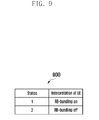
- FIGURE 9 illustrates a table 900 depicting the use of available downlink control information (DCI) code-points to turn on or turn off resource block RB bundling according to an embodiment of this disclosure.
- DCI downlink control information
- available DCI code-points are also used to dynamically turn on or off RB bundling.
- a state is defined to turn on RB bundling by adding an additional field to DCI format 2C.
- a first state indicated by the additional field is a state in which RB bundling is turned on or enabled.
- a second state indicated by the additional field is a state in which RB bundling is turned off or disabled.
- implicit signaling is used to turn on or off RB-bundling. For example, whether RB bundling is enabled is based on a specific transmission mode, the DCI format used for a DL grant, the transmission scheme, and the radio network temporary identifier (RNTI) configuration.
- RNTI radio network temporary identifier
- RB bundling is turned on or enabled if a UE is configured in Rel. 9 transmission mode (mode 8 in 3GPP 36.213), and if the UE received a physical downlink shared channel (PDSCH) packet scheduled with DCI format 2B.
- PDSCH physical downlink shared channel
- RB bundling is turned off or disabled. If the UE receives a PDSCH packet scheduled with DCI format 1A, and the associated transmission scheme is single antenna port transmission (1. scheduled by SPS-RNTI, and for the case when the PBCH signals one antenna port; or 2. scheduled by cell radio network temporary identifier (C-RNTI)), then RB bundling is turned on or enabled.
- SPS semi-persistent scheduling
- PBCH physical broadcast channel
- C-RNTI cell radio network temporary identifier
- RB bundling is turned on or enabled if a UE is configured in Rel. 10 transmission mode for both SU and MU MIMO transmission, and if the UE received a PDSCH packet scheduled with DCI format 2C (DCI format in Rel-10 used to support 2 codeword MIMO transmission).
- DCI format 2C DCI format in Rel-10 used to support 2 codeword MIMO transmission.
- RB bundling is turned off or disabled. If the UE receives a PDSCH packet scheduled with DCI format 1A, and the associated transmission scheme is single antenna port transmission (1. scheduled by SPS-RNTI, and for the case when the PBCH signals one antenna port; or 2. scheduled by C-RNTI), then RB bundling is turned on or enabled.
- RB bundling is turned on or off based on a specific feedback mode.
- RB bundling is turned on or enabled. Otherwise, if the UE is configured in Rel-10 and beyond Rel-10 transmission modes and PMI/RI feedback is not configured, RB bundling is turned off or disabled.
- FDD frequency-division duplexing
- an eNodeB may obtain the channel state information using uplink sounding to perform frequency selective precoding.
- PRB bundling should be turned off accordingly. Furthermore, even in FDD systems, when the eNodeB decides to perform open-loop operations, the eNodeB will not configure the UE to feedback PMI/RI. Therefore, PRB bundling is also turned off in this case to allow for flexible operation at the eNodeB.
- RB bundling is turned on or enabled.
- subband CQI/PMI/RI subband CQI
- an RB bundling on/off indication can also be realized through other system indications from the eNodeB to the UE.
- RB bundling is enabled once the rank indicator (RI) is greater than a predetermined value.
- RB bundling is always on for demodulation using Rel. 9 or Rel. 10 UE-RS.
- the UE In order to perform different types of feedback reports, the UE is configured by the eNodeB in different feedback modes.
- RB-bundling is turned on or off based on the specific feedback mode configured by the eNodeB.
- RB-bundling is turned on or off based on the specific physical uplink control channel (PUCCH) feedback mode.
- PUCCH physical uplink control channel
- RB bundling is turned on or enabled when when the UE is configured with PMI/RI reporting, and RB bundling is turned off or disabled when the UE is not configured with PMI/RI reporting.
- the pre-coding granularity at the eNodeB is multiple physical resource blocks. That is the eNodeB performs the same pre-coding over a bundled resource block where a bundled resource block comprises multiple consecutive physical resource blocks.
- the feedback granularity at the UE is set to multiple physical resource blocks such that the UE performs a channel estimation over a bundled resource block where a bundled resource block comprises multiple consecutive physical resource blocks.
- the pre-coding granularity at the eNodeB is a single physical resource block. That is the eNodeB performs pre-coding on a per physical resource block basis.
- the feedback granularity at the UE is set to a single physical resource block such that the UE performs a channel estimation on a per physical resource block basis.
- RB bundling is turned on or enabled when the UE is configured in mode 1-1 and mode 2-1 of Table 7.2.2-1, and RB bundling is turned off or disabled when the UE is configured in mode 1-0 and mode 2-0.
- RB-bundling is turned on or off based on the based on the specific physical uplink shared channel (PUSCH) feedback mode.
- PUSCH physical uplink shared channel
- RB bundling is turned on or enabled when the UE is configured for "single PMI" and/or “multiple PMI” feedback, and RB bundling is turned off or disabled otherwise.
- RB bundling is turned on or enabled when the UE is configured for "single PMI” feedback, and RB bundling is turned off or disabled when the UE is configured for "No PMI” or “Multiple PMI” feedback.
- RB bundling is turned on or enabled when the UE is configured for "single PMI” and “Multiple PMI” feedback, and RB bundling is turned off or disabled when the UE is configured for "No PMI” feedback.
- RB bundling is turned on or enabled when the UE is configured for "Multiple PMI” feedback, and RB-bundling is turned off or disabled when the UE is configured for "No PMI” or “Single PMI” feedback.
- RB bundling is turned on or enabled when the UE is configured in mode 3-1, and RB bundling is turned off or disabled in other feedback modes.
- the granularity of the RB bundling has to be decided. As described earlier, the granularity of the RB bundling refers to the number of continuous PRBs used for channel estimation and demodulation.
- the RB-bundling granularity is set to be the unit of downlink resource allocation.
- the unit of downlink resource allocation is a resource block group (RBG)
- RBG resource block group
- the size of RBG is dependent on the total system bandwidth. Therefore, the granularity of RB bundling can be the RBG size.
- the RB-bundling granularity is set to be the feedback granularity.
- the feedback granularity refers to the number of continuous RBs used by the UE to perform PMI/CQI/RI feedback.
- feedback granularity for PUSCH feedback is the subband size defined in Section 7.2.1 for higher layer-configured subband feedback or UE-selected subband feedback.
- the feedback granularity for PUCCH feedback is defined in Section 7.2.2.
- the RB-bundling granularity is set to be the subband size of the PUCCH feedback as a function of the total system bandwidth.
- the RB-bundling granularity is related to the subband size of the PUSCH feedback.
- the granularity of RB is the subband size of the corresponding feedback mode.
- FIGURE 10 illustrates subbands bundled together according to an embodiment of this disclosure.
- the RB-bundling granularity is set to be jointly decided by the feedback granularity as well as the downlink resource allocation unit.
- Feedback granularity refers to the number of continuous RBs used by the UE to perform PMI/CQI/RI feedback.
- the eNodeB would perform downlink precoding based on the UE feedback subband size, and the UE would assume the RBs in the downlink resource allocation from the same subband bundled together as shown in FIGURE 10 .
- a first subband 1010 includes a first RB bundle 1001
- a second subband 1020 includes a second RB bundle 1011.
- the first RB bundle 1001 and the second RB bundle 1011 are bundled together to form an RBG 1030.
- the RB-bundling granularity is set according to the subband size associated with the configured feedback modes.
- the RB-bundling granularity depends on the configured PUSCH feedback modes.
- RB bundling follows the subband size from the UE PUSCH feedback and/or the resource block group (RBG) size.
- RB bundling is turned off or disabled.
- the RB-bundling granularity depends on the configured PUCCH feedback modes.
- RB bundling follows the subband size from the PUCCH feedback (higher layer configured feedback subband size) and/or the RBG size.
- RB bundling is turned off or disabled.
- the size of RB bundling is fixed.
- the size of RB bundling can be an even number to facilitate pattern rotation of UE-RS patterns for higher ranks as suggested in R1-094575, "Discussion on DM-RS for LTE-Advanced", Samsung, November 2009, which is hereby incorporated by reference into the present application as if fully set forth herein.
- FIGURE 11 illustrates a DCI format 2C 1100 according to an embodiment of this disclosure.
- DCI format 2C 1100 is constructed by adding a new N3-bit for the indication of a combination of a selected DM RS pattern and a DM RS index set to DCI format 2B to support dynamic switching of SU- and MU-MIMO.
- a new data indicator (NDI) bit of a disabled transport block (TB) in DCI format 2B is used for indicating a DM RS index in the case of rank-1 indication in Rel-9 LTE.
- this embodiment uses codepoints constructed by a combination of an NDI bit of a disabled TB, such as the NDI bit in NDI field 1101 or NDI field 1103, and the new N3-bit in the N3-bit field 1105 for indicating rank-1 states in the restricted subset.
- FIGURE 12 illustrates a table 1200 depicting restricted subsets according to an embodiment of this disclosure.
- a state in a restricted subset A is signalled by DCI format 2C, where the restricted subset A is shown in table 1200 as an example.
- the restricted subset A is constructed such that all possible states from Rank-2 patterns A and B are included, no Rank-2 states from Rank-4 are included, and only higher rank states are included from Rank-8.
- - MU-MIMO is explicitly supported only for rank-1 with orthogonal UE-RS in Rank-2 and Rank-4 patterns;
- FIGURE 13 illustrates a table 1300 depicting a mapping of states in a restricted subset to codepoints in DCI format 2C according to an embodiment of this disclosure.
- FIGURE 13 illustrates one example mapping of states in restricted subset A to codepoints in DCI format 2C.
- FIGURE 14 illustrates a table 1400 depicting restricted subsets according to another embodiment of this disclosure.
- a state in restricted subset B is signalled by DCI format 2C.
- the restricted subset B is constructed such that all possible states from Rank-2 patterns A and B are included, no Rank-2 states from Rank-4 are included, and only higher rank states are included from Rank-8.
- the motivations of this subset restriction are that:
- - MU-MIMO is explicitly supported for rank-1 with orthogonal UE-RS in Rank-2 and Rank-4 patterns;
- FIGURE 15 illustrates a table 1500 depicting a mapping of states in a restricted subset to codepoints in DCI format 2C according to another embodiment of this disclosure.
- FIGURE 15 illustrates one example mapping of states in restricted subset B to codepoints in DCI format 2C.
- FIGURE 16 illustrates a method 1600 of operating a base station according to an embodiment of this disclosure.
- the method 1600 includes transmitting an indication of either a first feedback mode or a second feedback mode to a subscriber station (block 1601) and determining whether the first feedback mode is indicated by the indicator (block 1603).
- the method 1600 also includes setting the pre-coding granularity at the base station to multiple physical resource blocks in the frequency domain such that the base station performs the same pre-coding over a bundled resource block where a bundled resource block comprises multiple consecutive physical resource blocks in the frequency domain if the first feedback mode is indicated by the indicator (block 1605) and setting the pre-coding granularity at the base station to one physical resource block if the second feedback mode is indicated by the indicator (block 1607).
- the method 1600 further includes receiving feedback from the subscriber station (block 1609).
- FIGURE 17 illustrates a method 1700 of operating a subscriber station according to an embodiment of this disclosure.
- the method 1700 includes receiving an indication of a first feedback mode or a second feedback mode from a base station (block 1701), and determining whether the first feedback mode is indicated by the indicator (block 1703).
- the method 1700 also includes performing a channel estimation over a bundled resource block where a bundled resource block comprises multiple consecutive physical resource blocks in the frequency domain if the first feedback mode is indicated by the indicator (block 1705), and performing channel estimation only on a per physical resource block basis if the second feedback mode is indicated by the indicator (block 1707) .
- the method 1700 further includes transmitting the channel estimation as feedback to the base station (block 1709).
- FIGURE 18 illustrates a method 1800 of operating a base station according to another embodiment of this disclosure.
- the method 1800 includes transmitting an indication of whether a subscriber station is configured with precoding matrix indicator/rank indicator (PMI/RI) reporting (block 1801), and determining whether the subscriber station is configured with PMI/RI reporting (block 1803).
- the method 1800 also includes setting the pre-coding granularity at the base station to multiple physical resource blocks in the frequency domain such that the base station performs the same pre-coding over a bundled resource block where a bundled resource block comprises multiple consecutive physical resource blocks in the frequency domain if the subscriber station is configured with PMI/RI reporting (block 1805) and setting the pre-coding granularity at the base station to one physical resource block if the subscriber station is not configured with PMI/RI reporting (block 1807).
- the method 1800 further includes receiving feedback from the subscriber station (block 1809).
- FIGURE 19 illustrates a method 1900 of operating a subscriber station according to another embodiment of this disclosure.
- the method 1900 includes receiving from a base station an indication of whether the subscriber station is configured with precoding matrix indicator/rank indicator (PMI/RI) reporting (block 1901), and determining whether the subscriber station is configured with PMI/RI reporting (block 1903).
- the method 1900 also includes performing a channel estimation over a bundled resource block where a bundled resource block comprises multiple consecutive physical resource blocks in the frequency domain if the subscriber station is configured with PMI/RI reporting (block 1905), and performing channel estimation only on a per physical resource block basis if the subscriber station is not configured with PMI/RI reporting (block 1907).
- the method 1900 further includes transmitting the channel estimation as feedback to the base station (block 1909).
Priority Applications (1)
| Application Number | Priority Date | Filing Date | Title |
|---|---|---|---|
| EP14171879.1A EP2779516B1 (fr) | 2010-01-11 | 2011-01-04 | Procédé et système pour activer le regroupement de blocs de ressources dans des systèmes lte-a |
Applications Claiming Priority (2)
| Application Number | Priority Date | Filing Date | Title |
|---|---|---|---|
| US29401010P | 2010-01-11 | 2010-01-11 | |
| US12/970,717 US9253784B2 (en) | 2010-01-11 | 2010-12-16 | Method and system for enabling resource block bundling in LTE-A systems |
Related Child Applications (2)
| Application Number | Title | Priority Date | Filing Date |
|---|---|---|---|
| EP14171879.1A Division-Into EP2779516B1 (fr) | 2010-01-11 | 2011-01-04 | Procédé et système pour activer le regroupement de blocs de ressources dans des systèmes lte-a |
| EP14171879.1A Division EP2779516B1 (fr) | 2010-01-11 | 2011-01-04 | Procédé et système pour activer le regroupement de blocs de ressources dans des systèmes lte-a |
Publications (3)
| Publication Number | Publication Date |
|---|---|
| EP2343850A2 true EP2343850A2 (fr) | 2011-07-13 |
| EP2343850A3 EP2343850A3 (fr) | 2013-11-27 |
| EP2343850B1 EP2343850B1 (fr) | 2017-08-23 |
Family
ID=43501486
Family Applications (2)
| Application Number | Title | Priority Date | Filing Date |
|---|---|---|---|
| EP14171879.1A Active EP2779516B1 (fr) | 2010-01-11 | 2011-01-04 | Procédé et système pour activer le regroupement de blocs de ressources dans des systèmes lte-a |
| EP11150088.0A Active EP2343850B1 (fr) | 2010-01-11 | 2011-01-04 | Procédé et système pour activer le regroupement de blocs de ressources dans des systèmes lte-a |
Family Applications Before (1)
| Application Number | Title | Priority Date | Filing Date |
|---|---|---|---|
| EP14171879.1A Active EP2779516B1 (fr) | 2010-01-11 | 2011-01-04 | Procédé et système pour activer le regroupement de blocs de ressources dans des systèmes lte-a |
Country Status (9)
| Country | Link |
|---|---|
| US (3) | US9253784B2 (fr) |
| EP (2) | EP2779516B1 (fr) |
| JP (2) | JP5714608B2 (fr) |
| KR (1) | KR101721538B1 (fr) |
| CN (2) | CN102714566B (fr) |
| AU (1) | AU2011204107B2 (fr) |
| CA (1) | CA2786034C (fr) |
| RU (1) | RU2549351C2 (fr) |
| WO (1) | WO2011083972A2 (fr) |
Cited By (3)
| Publication number | Priority date | Publication date | Assignee | Title |
|---|---|---|---|---|
| WO2011163273A1 (fr) * | 2010-06-21 | 2011-12-29 | Qualcomm Incorporated | Regroupement de blocs de ressources physiques (prb) pour la formation de faisceau en boucle ouverte |
| CN104012016A (zh) * | 2011-10-20 | 2014-08-27 | 三星电子株式会社 | 无线通信系统中发送和接收控制信息的方法和装置 |
| CN110266432A (zh) * | 2012-05-11 | 2019-09-20 | 华为技术有限公司 | 触发信道状态信息非周期反馈的方法、ue、基站及系统 |
Families Citing this family (62)
| Publication number | Priority date | Publication date | Assignee | Title |
|---|---|---|---|---|
| KR101641968B1 (ko) | 2009-09-14 | 2016-07-29 | 엘지전자 주식회사 | 다중입출력 무선 통신 시스템에서 하향링크 신호 전송 방법 및 장치 |
| US9253784B2 (en) | 2010-01-11 | 2016-02-02 | Samsung Electronics Co., Ltd. | Method and system for enabling resource block bundling in LTE-A systems |
| WO2011096646A2 (fr) | 2010-02-07 | 2011-08-11 | Lg Electronics Inc. | Procédé et appareil pour émettre un signal de référence descendant dans un système de communication sans fil prenant en charge plusieurs antennes |
| US20110255483A1 (en) * | 2010-04-16 | 2011-10-20 | Research In Motion Limited | Signaling of Precoding Granularity for LTE and LTE-A |
| CN102237961A (zh) * | 2010-05-04 | 2011-11-09 | 株式会社Ntt都科摩 | 一种多输入多输出相关信息传输方法 |
| US8401105B2 (en) | 2010-06-10 | 2013-03-19 | Intel Mobile Communications GmbH | Method for transmitting a data signal in a MIMO system |
| US9130708B2 (en) * | 2010-06-18 | 2015-09-08 | Qualcomm Incorporated | Method and apparatus for bundling resource blocks in wireless communication |
| US9941998B2 (en) * | 2010-06-24 | 2018-04-10 | Qualcomm Incorporated | Control information signaling for MIMO transmissions |
| EP2684328B1 (fr) * | 2011-03-30 | 2016-06-22 | Huawei Technologies Co., Ltd. | Procédé et appareil utilisés pour une transmission en boucle ouverte dans un système de communication sans fils multi-antenne |
| MX2013011811A (es) * | 2011-04-13 | 2014-01-23 | Ericsson Telefon Ab L M | Metodo y dispositivo para la gestion del bufer del soft con base de las categorias de los equipos del usuario en una red de comunicaciones. |
| US8995291B2 (en) * | 2011-06-10 | 2015-03-31 | Qualcomm Incorporated | Tracking loop design for unicast and multicast/broadcast signals |
| CN102843209B (zh) * | 2011-06-22 | 2015-09-30 | 华为技术有限公司 | 传输控制信令的方法和装置 |
| EP2544420A1 (fr) * | 2011-07-07 | 2013-01-09 | Alcatel Lucent | Procédé de transmission de données dans un système de communication, premier noeud de réseau et deuxième noeud de réseau correspondants |
| US9306638B2 (en) | 2011-08-25 | 2016-04-05 | Qualcomm Incorporated | Backhaul enhancements for cooperative multi-point (CoMP) operations |
| CN103312396B (zh) * | 2012-03-15 | 2018-05-11 | 中兴通讯股份有限公司 | Mimo预编码的方法及基站 |
| WO2013168958A1 (fr) * | 2012-05-07 | 2013-11-14 | 엘지전자 주식회사 | Procédé et dispositif utilisateur permettant la réception de données de liaison descendante, et procédé et station de base permettant l'émission de données de liaison descendante |
| US20130343299A1 (en) * | 2012-06-21 | 2013-12-26 | Samsung Electronics Co., Ltd | Method for cqi feedback without spatial feedback (pmi/ri) for tdd coordinated multi-point and carrier aggregation scenarios |
| JP6014264B2 (ja) * | 2012-08-30 | 2016-10-25 | エルジー エレクトロニクス インコーポレイティド | 無線通信システムにおいてチャネルを推定する方法および装置 |
| WO2014047785A1 (fr) * | 2012-09-25 | 2014-04-03 | Panasonic Corporation | Procédé de communication sans fil de signalisation d'états comp, point de transmission et équipement utilisateur afférents |
| EP2930968B1 (fr) * | 2012-12-09 | 2019-02-27 | LG Electronics Inc. | Procédé de réintroduction d'informations de statut de canal dans un système de communication sans fil accueillant des antennes multiples, et son appareil |
| CN103905141B (zh) * | 2012-12-26 | 2018-09-25 | 中兴通讯股份有限公司 | 一种物理下行共享信道的信道估计方法、系统及设备 |
| US9468022B2 (en) * | 2012-12-26 | 2016-10-11 | Samsung Electronics Co., Ltd. | Method and apparatus for random access in communication system with large number of antennas |
| CN109639399B (zh) | 2013-02-28 | 2021-01-05 | 华为技术有限公司 | 通信方法和装置 |
| WO2014137154A2 (fr) * | 2013-03-06 | 2014-09-12 | 엘지전자 주식회사 | Procédé pour appliquer un regroupement de blocs de ressource physique (prb) dans un système de communication sans fil et appareil associé |
| CN104104472B (zh) * | 2013-04-10 | 2019-05-21 | 中兴通讯股份有限公司 | 一种保证预编码后信道连续性的方法、基站和ue |
| US9755810B2 (en) * | 2013-04-12 | 2017-09-05 | Qualcomm Incorporated | Precoder resource bundling information for interference cancellation in LTE |
| US20140348012A1 (en) * | 2013-05-27 | 2014-11-27 | Htc Corporation | Small cell communication system and operating method thefeof |
| US9392549B2 (en) * | 2013-06-11 | 2016-07-12 | Broadcom Corporation | Reducing precoder signaling overhead for MIMO communication system |
| EP3031242B1 (fr) * | 2013-08-06 | 2019-06-26 | Sun Patent Trust | Procédé de communication sans fil pour communications de dispositif à dispositif, et équipement d'utilisateur |
| JP6364206B2 (ja) * | 2014-02-28 | 2018-07-25 | 株式会社Nttドコモ | 無線基地局、ユーザ端末および無線通信方法 |
| CN106537802B (zh) * | 2014-07-24 | 2020-09-08 | Lg电子株式会社 | 用于发送反馈信号的方法和设备 |
| US10367551B2 (en) * | 2015-01-29 | 2019-07-30 | Intel Corporation | Precoding resource block group bundling enhancement for full dimension multi-in-multi-output |
| US10455544B2 (en) * | 2015-01-30 | 2019-10-22 | Qualcomm Incorporated | Enhanced paging procedures for machine type communications (MTC) |
| CN106302269B (zh) * | 2015-06-04 | 2020-06-23 | 电信科学技术研究院 | 一种信道状态信息的反馈及其控制方法及装置 |
| US10177886B2 (en) * | 2015-11-30 | 2019-01-08 | Telefonaktiebolaget Lm Ericsson (Publ) | Method and apparatus for configuring a cluster |
| CN107547181B (zh) * | 2016-06-25 | 2023-10-24 | 华为技术有限公司 | 控制信息发送方法、接收方法、网络设备和终端设备 |
| US10841041B2 (en) * | 2016-09-30 | 2020-11-17 | Sony Corporation | Infrastructure equipment, wireless telecommunications system and method for HARQ-ACK bundling |
| EP3510718B1 (fr) * | 2016-11-22 | 2022-08-03 | Samsung Electronics Co., Ltd. | Procédé et appareil d'estimation de canal et de décodage de données dans un système de communication sans fil |
| US10721038B2 (en) * | 2016-11-22 | 2020-07-21 | Samsung Electronics Co., Ltd. | Method and apparatus for channel estimation and data decoding in wireless communication system |
| KR102595898B1 (ko) | 2016-12-27 | 2023-10-30 | 삼성전자 주식회사 | 무선 통신 장치 및 이의 채널 추정 방법 |
| EP3570452B1 (fr) * | 2017-01-17 | 2023-03-01 | Guangdong Oppo Mobile Telecommunications Corp., Ltd. | Procédé et appareil de transmission de signal |
| CN108964866B (zh) * | 2017-03-24 | 2020-03-20 | 华为技术有限公司 | 一种参考信号发送方法、接收方法和装置 |
| KR102316752B1 (ko) | 2017-03-24 | 2021-10-25 | 삼성전자 주식회사 | 복수의 통신 서비스를 제공하기 위한 정보 송수신 방법 및 장치 |
| CN108123778B (zh) * | 2017-03-24 | 2023-04-11 | 中兴通讯股份有限公司 | 传输及传输配置方法、装置及基站、终端 |
| MX2019000574A (es) | 2017-04-24 | 2019-07-04 | Lg Electronics Inc | Metodo y aparato para transmitir o recibir la señal en el sistema de comunicacion inalambrica. |
| CN108811095B (zh) * | 2017-04-28 | 2024-04-12 | 华为技术有限公司 | 一种参数配置方法和装置 |
| CN108809492B (zh) * | 2017-05-04 | 2020-07-07 | 华为技术有限公司 | 数据传输方法和装置 |
| US10404432B2 (en) * | 2017-05-04 | 2019-09-03 | Nokia Technologies Oy | Methods and apparatuses for physical resource block bundling size configuration |
| CN109005591B (zh) | 2017-05-05 | 2019-09-20 | 华为技术有限公司 | 一种资源配置的方法及设备 |
| US10462801B2 (en) | 2017-05-05 | 2019-10-29 | At&T Intellectual Property I, L.P. | Multi-antenna transmission protocols for high doppler conditions |
| CN107359966B (zh) | 2017-05-31 | 2021-01-29 | 上海华为技术有限公司 | 一种信号的发射方法及通信设备 |
| US10749583B2 (en) * | 2017-06-14 | 2020-08-18 | Lg Electronics Inc. | Method for transmitting and receiving channel state information in wireless communication system and device for the same |
| US10470072B2 (en) | 2017-06-15 | 2019-11-05 | At&T Intellectual Property I, L.P. | Facilitation of multiple input multiple output communication for 5G or other next generation network |
| JP6770202B2 (ja) * | 2017-07-23 | 2020-10-14 | エルジー エレクトロニクス インコーポレイティド | 無線通信システムにおいてデータを送受信する方法及びそのための装置 |
| CN109309518B (zh) | 2017-07-26 | 2021-09-07 | 华为技术有限公司 | 用于数据传输的方法、装置和系统 |
| WO2019065634A1 (fr) * | 2017-09-27 | 2019-04-04 | 株式会社Nttドコモ | Équipement d'utilisateur et procédé de commande d'interférences |
| CN109802797B (zh) * | 2017-11-17 | 2021-03-05 | 维沃移动通信有限公司 | 确定信道状态信息参考信号的颗粒度的方法和网络设备 |
| CN109818711B (zh) * | 2017-11-21 | 2021-01-22 | 电信科学技术研究院 | 一种bundling大小确定方法、用户终端和网络侧设备 |
| ES2914382T3 (es) | 2018-01-12 | 2022-06-10 | Guangdong Oppo Mobile Telecommunications Corp Ltd | Método y dispositivo de transmisión de datos |
| US10869268B2 (en) * | 2018-01-19 | 2020-12-15 | Mediatek Inc. | NR power saving enhancements |
| US11128429B2 (en) * | 2018-10-05 | 2021-09-21 | Lenovo (Singapore) Pte. Ltd. | Method and apparatus for generating a CSI report |
| US11824688B2 (en) | 2018-11-21 | 2023-11-21 | Qualcomm Incorporated | Configuring channel state information reference signal subband precoding resource block groups |
Family Cites Families (19)
| Publication number | Priority date | Publication date | Assignee | Title |
|---|---|---|---|---|
| KR100996023B1 (ko) | 2005-10-31 | 2010-11-22 | 삼성전자주식회사 | 다중 안테나 통신 시스템에서 데이터 송수신 장치 및 방법 |
| US10044532B2 (en) | 2006-03-20 | 2018-08-07 | Texas Instruments Incorporated | Pre-coder selection based on resource block grouping |
| EP2797250B1 (fr) * | 2007-04-20 | 2017-12-20 | InterDigital Technology Corporation | Procédé et appareil pour une validation d'informations de précodage efficace de communications MIMO |
| KR101329854B1 (ko) * | 2007-06-05 | 2013-11-14 | 엘지전자 주식회사 | 다중안테나 시스템에서의 제어정보 전송방법 |
| US8989285B2 (en) | 2007-09-26 | 2015-03-24 | Samsung Electronics Co., Ltd. | Efficient MIMO precoding feedback scheme |
| KR100904433B1 (ko) | 2008-01-07 | 2009-06-24 | 엘지전자 주식회사 | 분산형 가상자원블록 스케쥴링 방법 |
| KR100913099B1 (ko) | 2008-01-07 | 2009-08-21 | 엘지전자 주식회사 | 분산형 가상자원블록 스케쥴링 방법 |
| US8179849B2 (en) | 2008-01-09 | 2012-05-15 | Rockstar Bidco, L.P. | Mapping of distributed resource block indices to physical resource blocks |
| KR100905385B1 (ko) | 2008-03-16 | 2009-06-30 | 엘지전자 주식회사 | 무선통신 시스템에서 제어신호의 효율적인 전송방법 |
| EP2117155B1 (fr) * | 2008-05-06 | 2014-03-19 | Godo Kaisha IP Bridge 1 | Contrôle de signalisation de canal pour déclencher la transmission indépendante d'un indicateur de qualité de canal |
| KR100987458B1 (ko) | 2008-06-24 | 2010-10-13 | 엘지전자 주식회사 | 상향링크 신호 전송 방법 |
| KR101565417B1 (ko) | 2008-08-08 | 2015-11-03 | 엘지전자 주식회사 | 다중 주파수 대역 시스템에서의 자원 할당하는 방법 및 장치 |
| AU2009307781B2 (en) * | 2008-10-20 | 2014-04-10 | Interdigital Patent Holdings, Inc | Carrier aggregation |
| US8284732B2 (en) * | 2009-02-03 | 2012-10-09 | Motorola Mobility Llc | Method and apparatus for transport block signaling in a wireless communication system |
| WO2010123893A1 (fr) * | 2009-04-22 | 2010-10-28 | Interdigital Patent Holdings, Inc. | Procédé et appareil pour transmettre des informations de commande de liaison montante pour des spectres agrégés de porteuse |
| US20110105137A1 (en) * | 2009-04-23 | 2011-05-05 | Qualcomm Incorporated | Rank and precoding indication for mimo operation |
| US20120270535A1 (en) * | 2009-12-17 | 2012-10-25 | Texas Instruments Incorporated | Implicit CSI Feedback for DL Multiuser MIMO Transmission |
| US9253784B2 (en) | 2010-01-11 | 2016-02-02 | Samsung Electronics Co., Ltd. | Method and system for enabling resource block bundling in LTE-A systems |
| WO2012052538A1 (fr) * | 2010-10-22 | 2012-04-26 | Nokia Siemens Networks Oy | Support de programmation, de coordination et de signalisation pour nœud d'accès inter-réseaux amélioré, pour algorithmes de réception perfectionnés |
-
2010
- 2010-12-16 US US12/970,717 patent/US9253784B2/en active Active
-
2011
- 2011-01-04 EP EP14171879.1A patent/EP2779516B1/fr active Active
- 2011-01-04 EP EP11150088.0A patent/EP2343850B1/fr active Active
- 2011-01-06 CN CN201180005809.8A patent/CN102714566B/zh active Active
- 2011-01-06 CN CN201410331905.7A patent/CN104065602B/zh active Active
- 2011-01-06 RU RU2012124082/07A patent/RU2549351C2/ru active
- 2011-01-06 JP JP2012548877A patent/JP5714608B2/ja active Active
- 2011-01-06 KR KR1020127017788A patent/KR101721538B1/ko active IP Right Grant
- 2011-01-06 AU AU2011204107A patent/AU2011204107B2/en active Active
- 2011-01-06 WO PCT/KR2011/000062 patent/WO2011083972A2/fr active Application Filing
- 2011-01-06 CA CA2786034A patent/CA2786034C/fr active Active
-
2014
- 2014-08-27 JP JP2014172400A patent/JP5862910B2/ja active Active
- 2014-12-15 US US14/571,171 patent/US9516655B2/en active Active
-
2016
- 2016-11-29 US US15/363,930 patent/US10333597B2/en active Active
Non-Patent Citations (9)
| Title |
|---|
| "Discussion on DM-RS for LTE-Advanced", SAMSUNG, November 2009 (2009-11-01) |
| "E-UTRA, Physical channels and modulation", 3GPP TS 36.211 V 8.8.0, December 2009 (2009-12-01) |
| "E-UTRA, Physical Layer Procedures", 3GPP TS 36.213 V 8.8.0, December 2009 (2009-12-01) |
| "Further investigation on DMRS design for LTE-A", CATT, November 2009 (2009-11-01) |
| "On Rel-10 DM RS design for rank 5-8", ERICSSON, ST-ERICSSON, November 2009 (2009-11-01) |
| "UE-RS Patterns for LTE-A", QUALCOMM EUROPE, August 2009 (2009-08-01) |
| "Way forward on CoMP and MIMO DL RS", OUTCOME OF AD HOC DISCUSSIONS, January 2009 (2009-01-01) |
| "Way forward on downlink reference signals for LTE-A", CATT, CMCC, ERICSSON, HUAWEI, LGE, MOTOROLA, NOKIA, NOKIA SIEMENS NETWORKS, NORTEL, PANASONIC, PHILIPS, QUALCOMM EUROPE, SAMSUNG, TEXAS INSTRUMENTS, March 2009 (2009-03-01) |
| "Way forward on the details of DCI format 2B for enhanced DL transmission", 3GPP RAN1#58BIS, MIYAZAKI, October 2009 (2009-10-01) |
Cited By (6)
| Publication number | Priority date | Publication date | Assignee | Title |
|---|---|---|---|---|
| WO2011163273A1 (fr) * | 2010-06-21 | 2011-12-29 | Qualcomm Incorporated | Regroupement de blocs de ressources physiques (prb) pour la formation de faisceau en boucle ouverte |
| US9148204B2 (en) | 2010-06-21 | 2015-09-29 | Qualcomm Incorporated | Physical resource block (PRB) bundling for open loop beamforming |
| CN104012016A (zh) * | 2011-10-20 | 2014-08-27 | 三星电子株式会社 | 无线通信系统中发送和接收控制信息的方法和装置 |
| US9591621B2 (en) | 2011-10-20 | 2017-03-07 | Samsung Electronics Co., Ltd | Method and apparatus for transmitting and receiving control channel information on an enhanced physical downlink control channel (ePDCCH) using an enhanced control channel element (eCCE) |
| CN104012016B (zh) * | 2011-10-20 | 2017-03-22 | 三星电子株式会社 | 无线通信系统中发送和接收控制信息的方法和装置 |
| CN110266432A (zh) * | 2012-05-11 | 2019-09-20 | 华为技术有限公司 | 触发信道状态信息非周期反馈的方法、ue、基站及系统 |
Also Published As
| Publication number | Publication date |
|---|---|
| AU2011204107A1 (en) | 2012-07-05 |
| EP2343850B1 (fr) | 2017-08-23 |
| CA2786034A1 (fr) | 2011-07-14 |
| US20110170498A1 (en) | 2011-07-14 |
| CN104065602B (zh) | 2017-08-15 |
| US9253784B2 (en) | 2016-02-02 |
| WO2011083972A2 (fr) | 2011-07-14 |
| EP2779516A1 (fr) | 2014-09-17 |
| US9516655B2 (en) | 2016-12-06 |
| RU2549351C2 (ru) | 2015-04-27 |
| RU2012124082A (ru) | 2014-02-20 |
| AU2011204107B2 (en) | 2016-04-14 |
| CN102714566B (zh) | 2015-10-21 |
| JP2013516936A (ja) | 2013-05-13 |
| JP5862910B2 (ja) | 2016-02-16 |
| WO2011083972A3 (fr) | 2011-12-01 |
| US20170141824A1 (en) | 2017-05-18 |
| CA2786034C (fr) | 2019-01-15 |
| CN104065602A (zh) | 2014-09-24 |
| CN102714566A (zh) | 2012-10-03 |
| KR20120135201A (ko) | 2012-12-12 |
| US10333597B2 (en) | 2019-06-25 |
| EP2343850A3 (fr) | 2013-11-27 |
| JP5714608B2 (ja) | 2015-05-07 |
| EP2779516B1 (fr) | 2020-03-04 |
| US20150146658A1 (en) | 2015-05-28 |
| KR101721538B1 (ko) | 2017-03-30 |
| US20180006691A9 (en) | 2018-01-04 |
| JP2014241633A (ja) | 2014-12-25 |
Similar Documents
| Publication | Publication Date | Title |
|---|---|---|
| US10333597B2 (en) | Method and system for enabling block bundling in LTE-A systems | |
| US9295051B2 (en) | Systems and methods for bundling resource blocks in a wireless communication network | |
| US9131492B2 (en) | Method and system of multi-layer beamforming | |
| EP2443778B1 (fr) | Procédé et système d'indication du procédé utilisé pour brouiller des signaux de référence dédiés | |
| EP2540006B1 (fr) | Procédé et système pour indiquer un bloc de transport activé | |
| US20100195748A1 (en) | Method and system for reference signal pattern design in resource blocks | |
| JP2013528029A (ja) | アップリンク制御情報をマッピングするための方法及びシステム | |
| EP2378698B1 (fr) | Systèmes et procédé pour regrouper des blocs de ressources dans un système de communication sans fil |
Legal Events
| Date | Code | Title | Description |
|---|---|---|---|
| PUAI | Public reference made under article 153(3) epc to a published international application that has entered the european phase |
Free format text: ORIGINAL CODE: 0009012 |
|
| AK | Designated contracting states |
Kind code of ref document: A2 Designated state(s): AL AT BE BG CH CY CZ DE DK EE ES FI FR GB GR HR HU IE IS IT LI LT LU LV MC MK MT NL NO PL PT RO RS SE SI SK SM TR |
|
| AX | Request for extension of the european patent |
Extension state: BA ME |
|
| RAP1 | Party data changed (applicant data changed or rights of an application transferred) |
Owner name: SAMSUNG ELECTRONICS CO., LTD. |
|
| PUAL | Search report despatched |
Free format text: ORIGINAL CODE: 0009013 |
|
| AK | Designated contracting states |
Kind code of ref document: A3 Designated state(s): AL AT BE BG CH CY CZ DE DK EE ES FI FR GB GR HR HU IE IS IT LI LT LU LV MC MK MT NL NO PL PT RO RS SE SI SK SM TR |
|
| AX | Request for extension of the european patent |
Extension state: BA ME |
|
| RIC1 | Information provided on ipc code assigned before grant |
Ipc: H04L 5/00 20060101AFI20131023BHEP Ipc: H04L 25/03 20060101ALI20131023BHEP Ipc: H04L 25/02 20060101ALI20131023BHEP |
|
| 17P | Request for examination filed |
Effective date: 20140327 |
|
| RBV | Designated contracting states (corrected) |
Designated state(s): AL AT BE BG CH CY CZ DE DK EE ES FI FR GB GR HR HU IE IS IT LI LT LU LV MC MK MT NL NO PL PT RO RS SE SI SK SM TR |
|
| GRAP | Despatch of communication of intention to grant a patent |
Free format text: ORIGINAL CODE: EPIDOSNIGR1 |
|
| INTG | Intention to grant announced |
Effective date: 20170518 |
|
| GRAS | Grant fee paid |
Free format text: ORIGINAL CODE: EPIDOSNIGR3 |
|
| GRAA | (expected) grant |
Free format text: ORIGINAL CODE: 0009210 |
|
| AK | Designated contracting states |
Kind code of ref document: B1 Designated state(s): AL AT BE BG CH CY CZ DE DK EE ES FI FR GB GR HR HU IE IS IT LI LT LU LV MC MK MT NL NO PL PT RO RS SE SI SK SM TR |
|
| REG | Reference to a national code |
Ref country code: GB Ref legal event code: FG4D |
|
| REG | Reference to a national code |
Ref country code: CH Ref legal event code: EP |
|
| REG | Reference to a national code |
Ref country code: AT Ref legal event code: REF Ref document number: 922382 Country of ref document: AT Kind code of ref document: T Effective date: 20170915 |
|
| REG | Reference to a national code |
Ref country code: IE Ref legal event code: FG4D |
|
| REG | Reference to a national code |
Ref country code: DE Ref legal event code: R096 Ref document number: 602011040775 Country of ref document: DE |
|
| REG | Reference to a national code |
Ref country code: NL Ref legal event code: FP |
|
| REG | Reference to a national code |
Ref country code: LT Ref legal event code: MG4D |
|
| REG | Reference to a national code |
Ref country code: AT Ref legal event code: MK05 Ref document number: 922382 Country of ref document: AT Kind code of ref document: T Effective date: 20170823 |
|
| REG | Reference to a national code |
Ref country code: FR Ref legal event code: PLFP Year of fee payment: 8 |
|
| PG25 | Lapsed in a contracting state [announced via postgrant information from national office to epo] |
Ref country code: FI Free format text: LAPSE BECAUSE OF FAILURE TO SUBMIT A TRANSLATION OF THE DESCRIPTION OR TO PAY THE FEE WITHIN THE PRESCRIBED TIME-LIMIT Effective date: 20170823 Ref country code: AT Free format text: LAPSE BECAUSE OF FAILURE TO SUBMIT A TRANSLATION OF THE DESCRIPTION OR TO PAY THE FEE WITHIN THE PRESCRIBED TIME-LIMIT Effective date: 20170823 Ref country code: SE Free format text: LAPSE BECAUSE OF FAILURE TO SUBMIT A TRANSLATION OF THE DESCRIPTION OR TO PAY THE FEE WITHIN THE PRESCRIBED TIME-LIMIT Effective date: 20170823 Ref country code: LT Free format text: LAPSE BECAUSE OF FAILURE TO SUBMIT A TRANSLATION OF THE DESCRIPTION OR TO PAY THE FEE WITHIN THE PRESCRIBED TIME-LIMIT Effective date: 20170823 Ref country code: NO Free format text: LAPSE BECAUSE OF FAILURE TO SUBMIT A TRANSLATION OF THE DESCRIPTION OR TO PAY THE FEE WITHIN THE PRESCRIBED TIME-LIMIT Effective date: 20171123 Ref country code: HR Free format text: LAPSE BECAUSE OF FAILURE TO SUBMIT A TRANSLATION OF THE DESCRIPTION OR TO PAY THE FEE WITHIN THE PRESCRIBED TIME-LIMIT Effective date: 20170823 |
|
| PG25 | Lapsed in a contracting state [announced via postgrant information from national office to epo] |
Ref country code: RS Free format text: LAPSE BECAUSE OF FAILURE TO SUBMIT A TRANSLATION OF THE DESCRIPTION OR TO PAY THE FEE WITHIN THE PRESCRIBED TIME-LIMIT Effective date: 20170823 Ref country code: BG Free format text: LAPSE BECAUSE OF FAILURE TO SUBMIT A TRANSLATION OF THE DESCRIPTION OR TO PAY THE FEE WITHIN THE PRESCRIBED TIME-LIMIT Effective date: 20171123 Ref country code: IS Free format text: LAPSE BECAUSE OF FAILURE TO SUBMIT A TRANSLATION OF THE DESCRIPTION OR TO PAY THE FEE WITHIN THE PRESCRIBED TIME-LIMIT Effective date: 20171223 Ref country code: GR Free format text: LAPSE BECAUSE OF FAILURE TO SUBMIT A TRANSLATION OF THE DESCRIPTION OR TO PAY THE FEE WITHIN THE PRESCRIBED TIME-LIMIT Effective date: 20171124 Ref country code: ES Free format text: LAPSE BECAUSE OF FAILURE TO SUBMIT A TRANSLATION OF THE DESCRIPTION OR TO PAY THE FEE WITHIN THE PRESCRIBED TIME-LIMIT Effective date: 20170823 Ref country code: PL Free format text: LAPSE BECAUSE OF FAILURE TO SUBMIT A TRANSLATION OF THE DESCRIPTION OR TO PAY THE FEE WITHIN THE PRESCRIBED TIME-LIMIT Effective date: 20170823 Ref country code: LV Free format text: LAPSE BECAUSE OF FAILURE TO SUBMIT A TRANSLATION OF THE DESCRIPTION OR TO PAY THE FEE WITHIN THE PRESCRIBED TIME-LIMIT Effective date: 20170823 |
|
| PG25 | Lapsed in a contracting state [announced via postgrant information from national office to epo] |
Ref country code: DK Free format text: LAPSE BECAUSE OF FAILURE TO SUBMIT A TRANSLATION OF THE DESCRIPTION OR TO PAY THE FEE WITHIN THE PRESCRIBED TIME-LIMIT Effective date: 20170823 Ref country code: RO Free format text: LAPSE BECAUSE OF FAILURE TO SUBMIT A TRANSLATION OF THE DESCRIPTION OR TO PAY THE FEE WITHIN THE PRESCRIBED TIME-LIMIT Effective date: 20170823 Ref country code: CZ Free format text: LAPSE BECAUSE OF FAILURE TO SUBMIT A TRANSLATION OF THE DESCRIPTION OR TO PAY THE FEE WITHIN THE PRESCRIBED TIME-LIMIT Effective date: 20170823 |
|
| REG | Reference to a national code |
Ref country code: DE Ref legal event code: R097 Ref document number: 602011040775 Country of ref document: DE |
|
| PG25 | Lapsed in a contracting state [announced via postgrant information from national office to epo] |
Ref country code: SM Free format text: LAPSE BECAUSE OF FAILURE TO SUBMIT A TRANSLATION OF THE DESCRIPTION OR TO PAY THE FEE WITHIN THE PRESCRIBED TIME-LIMIT Effective date: 20170823 Ref country code: SK Free format text: LAPSE BECAUSE OF FAILURE TO SUBMIT A TRANSLATION OF THE DESCRIPTION OR TO PAY THE FEE WITHIN THE PRESCRIBED TIME-LIMIT Effective date: 20170823 Ref country code: EE Free format text: LAPSE BECAUSE OF FAILURE TO SUBMIT A TRANSLATION OF THE DESCRIPTION OR TO PAY THE FEE WITHIN THE PRESCRIBED TIME-LIMIT Effective date: 20170823 |
|
| PLBE | No opposition filed within time limit |
Free format text: ORIGINAL CODE: 0009261 |
|
| STAA | Information on the status of an ep patent application or granted ep patent |
Free format text: STATUS: NO OPPOSITION FILED WITHIN TIME LIMIT |
|
| 26N | No opposition filed |
Effective date: 20180524 |
|
| PG25 | Lapsed in a contracting state [announced via postgrant information from national office to epo] |
Ref country code: SI Free format text: LAPSE BECAUSE OF FAILURE TO SUBMIT A TRANSLATION OF THE DESCRIPTION OR TO PAY THE FEE WITHIN THE PRESCRIBED TIME-LIMIT Effective date: 20170823 |
|
| REG | Reference to a national code |
Ref country code: CH Ref legal event code: PL |
|
| PG25 | Lapsed in a contracting state [announced via postgrant information from national office to epo] |
Ref country code: LU Free format text: LAPSE BECAUSE OF NON-PAYMENT OF DUE FEES Effective date: 20180104 |
|
| REG | Reference to a national code |
Ref country code: IE Ref legal event code: MM4A |
|
| REG | Reference to a national code |
Ref country code: BE Ref legal event code: MM Effective date: 20180131 |
|
| PG25 | Lapsed in a contracting state [announced via postgrant information from national office to epo] |
Ref country code: BE Free format text: LAPSE BECAUSE OF NON-PAYMENT OF DUE FEES Effective date: 20180131 Ref country code: CH Free format text: LAPSE BECAUSE OF NON-PAYMENT OF DUE FEES Effective date: 20180131 Ref country code: LI Free format text: LAPSE BECAUSE OF NON-PAYMENT OF DUE FEES Effective date: 20180131 |
|
| PG25 | Lapsed in a contracting state [announced via postgrant information from national office to epo] |
Ref country code: IE Free format text: LAPSE BECAUSE OF NON-PAYMENT OF DUE FEES Effective date: 20180104 |
|
| PG25 | Lapsed in a contracting state [announced via postgrant information from national office to epo] |
Ref country code: MC Free format text: LAPSE BECAUSE OF FAILURE TO SUBMIT A TRANSLATION OF THE DESCRIPTION OR TO PAY THE FEE WITHIN THE PRESCRIBED TIME-LIMIT Effective date: 20170823 |
|
| PG25 | Lapsed in a contracting state [announced via postgrant information from national office to epo] |
Ref country code: MT Free format text: LAPSE BECAUSE OF NON-PAYMENT OF DUE FEES Effective date: 20180104 |
|
| PG25 | Lapsed in a contracting state [announced via postgrant information from national office to epo] |
Ref country code: TR Free format text: LAPSE BECAUSE OF FAILURE TO SUBMIT A TRANSLATION OF THE DESCRIPTION OR TO PAY THE FEE WITHIN THE PRESCRIBED TIME-LIMIT Effective date: 20170823 |
|
| PG25 | Lapsed in a contracting state [announced via postgrant information from national office to epo] |
Ref country code: HU Free format text: LAPSE BECAUSE OF FAILURE TO SUBMIT A TRANSLATION OF THE DESCRIPTION OR TO PAY THE FEE WITHIN THE PRESCRIBED TIME-LIMIT; INVALID AB INITIO Effective date: 20110104 Ref country code: PT Free format text: LAPSE BECAUSE OF FAILURE TO SUBMIT A TRANSLATION OF THE DESCRIPTION OR TO PAY THE FEE WITHIN THE PRESCRIBED TIME-LIMIT Effective date: 20170823 |
|
| PG25 | Lapsed in a contracting state [announced via postgrant information from national office to epo] |
Ref country code: MK Free format text: LAPSE BECAUSE OF NON-PAYMENT OF DUE FEES Effective date: 20170823 Ref country code: CY Free format text: LAPSE BECAUSE OF FAILURE TO SUBMIT A TRANSLATION OF THE DESCRIPTION OR TO PAY THE FEE WITHIN THE PRESCRIBED TIME-LIMIT Effective date: 20170823 |
|
| PG25 | Lapsed in a contracting state [announced via postgrant information from national office to epo] |
Ref country code: AL Free format text: LAPSE BECAUSE OF FAILURE TO SUBMIT A TRANSLATION OF THE DESCRIPTION OR TO PAY THE FEE WITHIN THE PRESCRIBED TIME-LIMIT Effective date: 20170823 |
|
| PGFP | Annual fee paid to national office [announced via postgrant information from national office to epo] |
Ref country code: IT Payment date: 20221221 Year of fee payment: 13 Ref country code: DE Payment date: 20221220 Year of fee payment: 13 |
|
| PGFP | Annual fee paid to national office [announced via postgrant information from national office to epo] |
Ref country code: GB Payment date: 20231220 Year of fee payment: 14 |
|
| PGFP | Annual fee paid to national office [announced via postgrant information from national office to epo] |
Ref country code: NL Payment date: 20231221 Year of fee payment: 14 Ref country code: FR Payment date: 20231222 Year of fee payment: 14 |