EP2343232B1 - Suspension bicycle seat post - Google Patents
Suspension bicycle seat post Download PDFInfo
- Publication number
- EP2343232B1 EP2343232B1 EP11150268.8A EP11150268A EP2343232B1 EP 2343232 B1 EP2343232 B1 EP 2343232B1 EP 11150268 A EP11150268 A EP 11150268A EP 2343232 B1 EP2343232 B1 EP 2343232B1
- Authority
- EP
- European Patent Office
- Prior art keywords
- collar
- seat
- bicycle
- seat post
- passage
- Prior art date
- Legal status (The legal status is an assumption and is not a legal conclusion. Google has not performed a legal analysis and makes no representation as to the accuracy of the status listed.)
- Active
Links
Images


Classifications
-
- B—PERFORMING OPERATIONS; TRANSPORTING
- B62—LAND VEHICLES FOR TRAVELLING OTHERWISE THAN ON RAILS
- B62J—CYCLE SADDLES OR SEATS; AUXILIARY DEVICES OR ACCESSORIES SPECIALLY ADAPTED TO CYCLES AND NOT OTHERWISE PROVIDED FOR, e.g. ARTICLE CARRIERS OR CYCLE PROTECTORS
- B62J1/00—Saddles or other seats for cycles; Arrangement thereof; Component parts
- B62J1/08—Frames for saddles; Connections between saddle frames and seat pillars; Seat pillars
-
- B—PERFORMING OPERATIONS; TRANSPORTING
- B62—LAND VEHICLES FOR TRAVELLING OTHERWISE THAN ON RAILS
- B62J—CYCLE SADDLES OR SEATS; AUXILIARY DEVICES OR ACCESSORIES SPECIALLY ADAPTED TO CYCLES AND NOT OTHERWISE PROVIDED FOR, e.g. ARTICLE CARRIERS OR CYCLE PROTECTORS
- B62J1/00—Saddles or other seats for cycles; Arrangement thereof; Component parts
- B62J1/02—Saddles resiliently mounted on the frame; Equipment therefor, e.g. springs
- B62J1/04—Saddles capable of swinging about a horizontal pivot
-
- F—MECHANICAL ENGINEERING; LIGHTING; HEATING; WEAPONS; BLASTING
- F16—ENGINEERING ELEMENTS AND UNITS; GENERAL MEASURES FOR PRODUCING AND MAINTAINING EFFECTIVE FUNCTIONING OF MACHINES OR INSTALLATIONS; THERMAL INSULATION IN GENERAL
- F16F—SPRINGS; SHOCK-ABSORBERS; MEANS FOR DAMPING VIBRATION
- F16F1/00—Springs
- F16F1/36—Springs made of rubber or other material having high internal friction, e.g. thermoplastic elastomers
- F16F1/38—Springs made of rubber or other material having high internal friction, e.g. thermoplastic elastomers with a sleeve of elastic material between a rigid outer sleeve and a rigid inner sleeve or pin, i.e. bushing-type
- F16F1/3863—Springs made of rubber or other material having high internal friction, e.g. thermoplastic elastomers with a sleeve of elastic material between a rigid outer sleeve and a rigid inner sleeve or pin, i.e. bushing-type characterised by the rigid sleeves or pin, e.g. of non-circular cross-section
-
- B—PERFORMING OPERATIONS; TRANSPORTING
- B62—LAND VEHICLES FOR TRAVELLING OTHERWISE THAN ON RAILS
- B62K—CYCLES; CYCLE FRAMES; CYCLE STEERING DEVICES; RIDER-OPERATED TERMINAL CONTROLS SPECIALLY ADAPTED FOR CYCLES; CYCLE AXLE SUSPENSIONS; CYCLE SIDE-CARS, FORECARS, OR THE LIKE
- B62K2201/00—Springs used in cycle frames or parts thereof
- B62K2201/02—Rubber springs
Definitions
- the present invention relates generally to bicycles and, more particularly, to a bicycle seat post or handlebar suspension assembly that reduces shocks from being communicated between the bicycle frame and the rider.
- the primary structural component of a conventional two-wheel bicycle is the frame.
- Most bicycles are defined by a frame that is typically constructed from a set of tubular members that are connected together.
- the frame is constructed from members commonly referred to as the top tube, down tube, seat tube, seat stays and chain stays, and those members are joined together at intersections commonly referred to as the head tube, seat post, bottom bracket and rear dropout.
- a front wheel and a rear wheel are generally attached at forward and rearward locations, respectively, with respect to frame.
- a handlebar and a seat extend in an upward direction from the frame at locations that are generally between the front and rear wheels.
- the handlebar cooperates with a fork assembly to effectuate steering of the bicycle and the seat is oriented rearward of the handlebar and commonly supports a majority of the weight of the rider.
- the seat is generally rigidly attached to a stem tube or seat post that telescopically cooperates with a seat tube of the bicycle frame.
- Still others such as WO 93/11026 , which is considered as the closest prior art, disclose a device for springing or adjusting the bearing forces of a vehicle saddle and provide a pivoting axis that is direction transversely to a saddle support and in the direction of travel of the vehicle. Although oriented forward of a longitudinal axis of the seat tube of the frame, such devices provide pivoting of the saddle about an axis that is concentrically associated with a rubber-metal bushing that is fitted beneath the nose of the saddle.
- a bicycle seat post or handlebar suspension assembly that provides vibrational and impact dampening between the bicycle frame and the user interface.
- a seat post assembly that provides vibration dampening but maintains responsiveness to rider interaction with the seat and/or handlebars.
- the present invention provides a suspension bicycle seat post assembly that overcomes one or more of the aforementioned drawbacks.
- the invention provides a bicycle seat post assembly according to claim 1.
- a further aspect of the invention that can be combined with the above aspect discloses a bicycle assembly having a frame with a seat tube formed between a front wheel and a rear wheel that are attached to the frame.
- the bicycle assembly includes a seat post assembly according to claim 1 and that includes a stem, a collar, a shock dampener, and a hinge.
- the stem has a head portion and a stem portion that telescopically cooperates with the seat tube of the frame.
- a passage is formed through the head portion of the stem and extends in a direction that crosses a longitudinal axis of the frame and the collar is positioned within the passage.
- the shock dampener extends about at least a portion of the circumference of the collar between the collar and the head portion of the stem.
- the hinge connects the collar and the stem and a seat is secured to the collar and rotatable about the hinge relative to the frame.
- the pivotable connection between the tube or collar and the stem is formed by an over-centered association between portions of the tube or collar and the seat post. More preferably, the hinge is offset forward or reward of a vertical plane that passes through longitudinal axis of the tube. More preferably, the pin of the hinge is formed by an extension of the tube and the barrel of the hinge is formed by cavity formed in the seat post.
- the interface between the shock member and one or more of the collar and the seat post includes an index that laterally aligns the shock member with one or each of the collar and the seat post.
- the index includes a key and groove association that, when mated, laterally align the tube, shock member, and stem tube.
- the dampener or shock member extends about the entire circumference of the tube between the tube and the stem.
- the shock member has a cross-sectional thickness that is thicker at locations that are circumferentially offset from the hinge.
- FIG. 1 shows a bicycle 10 having a seat post assembly 12 that is constructed according to the present invention.
- Seat post assembly 12 attaches a seat 14 to a frame 16 of bicycle 10.
- Handlebars 18 are attached to frame 16 generally forward of seat 14 with respect to a longitudinal axis, indicated by arrow 20, of bicycle 10.
- Seat post assembly 12 includes a seat post 22 that slidably or telescopically engages a seat tube 24 of frame 16.
- Frame 16 includes a top tube 26 and a down tube 28 that extend forwardly from seat tube 24 to a head tube 30 that connects the generally forward ends of top tube and down tube 26, 28.
- Handlebars 18 are connected to a stem 32 that passes through head tube 30 and engages a fork crown 34.
- a pair of forks 36 extend from generally opposite ends of fork crown 34 and are constructed to support a front wheel assembly 38 at an end thereof or fork tip 40.
- Fork tips 40 engage generally opposite sides of an axle 42 that is constructed to engage a hub 44 of front wheel assembly 38.
- a number of spokes 46 extend from hub 44 to a rim 48 of front wheel assembly 38.
- a tire 50 is engaged with rim 48 such that rotation of tire 50, relative to forks 36, rotates rim 48 and hub 44.
- Bicycle 10 includes a front brake assembly 52 having an actuator 54 attached to handlebars 18 and a pair of brake pads 56 positioned on generally opposite sides of front wheel assembly 38. Brake pads 56 are constructed to engage a brake wall 58 of rim 48 thereby providing a stopping or slowing force to front wheel assembly 38.
- Bicycle 10 includes a rear wheel assembly 60 that is positioned generally concentrically about a rear axle 62 such that rear wheel assembly 60 rotates about rear axle 62.
- Crankset 68 includes a set of pedals 70 that is operably connected to a chain 72 via a one or more variable diameter chain ring or sprocket gears 74.
- Rotation of chain 72 communicates a drive force to a gear cluster 78 positioned at a rear section of bicycle 10.
- Gear cluster 78 is generally concentrically orientated with respect to rear axle 62 and can include one or more variable diameter gears.
- Gear cluster 78 is operationally connected to a hub 80 of rear wheel assembly 60.
- Rear wheel assembly 60 includes hub 80, a number of spokes 82, and a rim 84. Each of the number of spokes 82 extend between hub 80 and rim 84 and communicate the loading forces therebetween.
- rider operation of pedals 70 drives chain 72 thereby driving rear wheel assembly 60 which in turn propels bicycle 10.
- bicycle 10 is shown as what is commonly understood as a road bike or bicycle configured for operation primarily on paved surfaces. However, it is further appreciated that bicycle 10 could also be formed as an off-road or mountain bike and that a suspension seat post assembly according to the present invention is applicable across various bicycle configuration platforms.
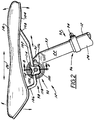
- seat post assembly 12 includes a suspension mount arrangement 90 that secures seat 14 to seat post 22 in a manner that allows limited movement therebetween.
- seat post 22 includes a first or stem portion 93 and a second portion or head portion 95 that is positioned near an end of stem portion 93.
- stem portion 93 is that portion of seat post 22 that can be received in seat tube 24
- head portion 95 is that portion of seat post 22, by virtue of its shape or contour, that cannot engage seat tube 24 when stem portion 93 is engaged therewith.
- a first end 92 of seat post 22 is associated with stem portion 93 and is telescopically received in seat tube 24 of bicycle frame 16.
- a clamp mechanism 94 is positioned about an opening 96 defined by seat tube 24. Clamp mechanism 94 compresses seat tube 24 about seat post 22 so as to define the generally vertical orientation of seat 14 with respect to frame 16. It is appreciated that seat post 22 and seat tube 24 could have any of a variety of complimentary shapes.
- a second end 98 of seat post 22 is formed proximate head portion 95 and is generally opposite first end 92.
- Suspension mount arrangement 90 is secured to seat post 22 proximate second end 98 and is generally remote or offset from first end 92.
- a removable seat rail clamp assembly 100 cooperates with mount arrangement 90 and engages a pair of seat rails 102 that extend from an underside 104 of seat 14.
- seat rail clamp assembly 100 is but one example of a rail clamp assembly useable with the present invention.
- Rails 102 extend from an underside 104 of seat 14. A first end 106 and a second end 108 of each rail 102 is secured to seat 14 at locations that are generally forward and rearward of mount arrangement 90 with respect to longitudinal axis 20.
- rail clamp assembly 100 includes a number of arms 112, 114, 116, 118 that are constructed to capture the alternate lateral rails 102 of seat 14 so as to secure seat 14 relative to suspension mount arrangement 90.
- a fastener 120 passes through rail clamp assembly 100 and is operable so that rails 102 and rail clamp assembly 100 can be conveniently and selectively secured with respect to suspension mount arrangement 90 and seat post 22. That is, those skilled in the art will appreciate that loosening fastener 120, allows forward or rearward tilting of seat 14 relative to suspension mount arrangement 90.
- Seat rail clamp assembly 100 is configured to be infinitely positionable with respect to suspension mount arrangement 90.
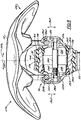
- suspension mount arrangement 90 includes a passage 130 that is formed through head portion 95 of seat post 22.
- Passage 130 includes a first section or portion 132 and a second section or portion 134 that are fluidly connected to one another.
- Passage 130 is formed along an axis 140 that extends in a lateral or crossing direction with respect to longitudinal axis 20 as shown in Fig. 2 .
- the lateral direction is commonly associated with the left and right sides of a bicycle and is generally orthogonal to longitudinal direction 20 of bicycle 10.
- Head portion 95 of seat post 22 includes a surface 142 that faces passage 130.
- Surface 142 includes an index or rib 144 and extends further into passage 130 than a majority of surface 142.
- rib 144 provides indexing of a shock, shock member, or suspension member 160 with respect to passage 130 and with respect to lateral directions aligned with axis 140.
- Suspension member 160 is preferably formed by a continuous body 162 and includes a first section or portion 164 and a second section or portion 166.
- body 162 is shown as being circumferentially continuous, it is appreciated that body 162 could be provided in a non-continuous manner wherein one or more of first and second portions 164, 166 are provided as isolated elements.
- first portion 164 of body 166 has a thicker radial dimension than second portion 166 of body 162.
- second portion 166 of body 162 is preferably thinner than first portion 164 of body 166.
- Body 162 of suspension member 160 includes a radially outward directed or exterior surface 168 and a radially inward or interior directed surface 170.
- a channel or groove 172 is formed along at least a portion of the circumference of body 162 in exterior surface 168 and interior surface 170 includes a rib 174 and extends in a radially inward direction with respect to a majority of interior radially interior directed surface 170 of body 162.
- groove 172 and rib 174 positionally index suspension member 160 with respect to both head portion 95 and a tube or collar 190 of mount arrangement 90.
- Body 162 of suspension member 160 defines a passage 180 having a first portion 182 and a second portion 183. Passage 180 extends in a direction that is generally aligned with axis 140. Collar 190 of mount arrangement 90 is received in passage 180 formed by suspension member 160. Collar 190 includes a body 192 having a first portion 194 that is configured to cooperate with first portion 182 of passage 180 and a second portion 196 that is configured to cooperate with second portion 183 of passage 180.
- Body 192 is preferably a continuous unitary part and includes a circumferentially oriented groove 198 formed on at least a portion of a radially directed exterior surface 200 of body 192. A pair of tapered surfaces or lands 204 are formed on an interior surface 202 of body 192.
- Lands 204 are each inclined in a longitudinally outward direction that is generally aligned along axis 140. Said in another way, lands 204 form truncated frustro-conical surfaces on a radially interior directed surface of body 192.
- a passage 206 is formed through body 192. Passage 206 is shaped to removably cooperate with seat rail clamp assembly 100.
- each of stem 22 and collar 190 are formed from generally rigid and robust materials such as metal-type materials and/or carbon fiber type materials.
- suspension member 160 is preferably constructed of elastomeric, rubber, or other shock or vibration dampening material.
- suspension member 160 is somewhat deformable but is robust enough to withstand static rider loading.
- Suspension member 160 is somewhat deformable to allow compression stacking of the suspension mount arrangement 90 via translation of collar 190 and suspension member 160 in either of axial directions 210, 212 with respect to head portion 95.
- the interaction of the various ribs and grooves laterally indexes each of head portion 95, suspension member 160, and collar 190 relative to one another. It is appreciated that the shape, arrangement, and number of ribs and grooves could be provided in virtually a limitless number of orientations.
- second portions 196 and 166 of collar 190 and suspension member 160 cooperate with second portion 134 of passage 130 formed in head portion 95 of seat post 22 and define a hinge assembly, hinged connection, or simply a hinge 220 between collar 190 and seat post 22.
- Hinge 220 limits the available motion of collar 190 relative to seat post 22 and suspension member 160 dampens motion within the range of the limited available motion. Said another way, hinge 220 prevents dissimilar lateral movements, indicated by arrows 224, 226 in Fig. 5 , of collar 190 relative to seat post 22.
- Hinge 220 and shock member 160 cooperate to dampen movement between collar 190 and seat post 22 in a manner that maintains a generally level horizontal orientation of the alternate lateral sides 272, 274 of seat 14.
- Seat 14 and seat rail clamp assembly 100 having limited motion based on rotation of collar 190 relative to head portion 95 about an axis 230 defined by hinge 220 as described further below with respect to Fig. 8 .
- hinge 220 is shown as being generally forward of longitudinal axis 259, it is envisioned that hinge 220 could be positioned anywhere along the circumferential space between collar 160 and head portion 95. Thos skilled in the art would appreciate that a hinge configuration as shown in Fig. 3 would be more beneficial to those riders that prefer to interact with more rearward positions of seat 14. It should also be understood that orienting hinge 220 rearward of axis 259 would provide better comfort and performance for those riders that prefer to be supported by the more forward or nose portions of seat 14. Understandably, moving hinge 220 about the circumferential interface between collar 190 and head portion 95 alters the position of the axis of rotation associated with suspension mount arrangement 90 thereby providing different dampening performance. It is further envisioned that head portion 95 could be provided with more than one recess that cooperates with the pin portion of hinge 220. Such a configuration would provide a single seat post assembly that could be configured to provide a number of unique suspension configurations.
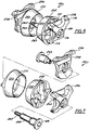
- FIGs. 6 and 7 show rail clamp assembly 100 removed from mount arrangement 90 of seat post 22.
- Rail clamp assembly 100 includes a pair of wedge bodies 231, 232 and a pair of clamp bodies 234, 236 that are positioned laterally outboard relative to wedge bodies 231, 232.
- Fastener 120 includes a stem portion 240 and a threaded portion 242 that threadingly cooperates with a shaft nut 246 that engages clamp assembly 100 from a direction laterally opposite fastener 120.
- Each wedge body 231, 232 includes a tapered surface 250, 252 that cooperates in a generally planer manner of the tapered surfaces or lands 204 of collar 190 as shown in Fig. 5 .
- Each clamp body 234, 236 includes a laterally inward facing rail groove 258, 260 that is configured to capture a corresponding seat rail 102 between a wedge and clamp body pair 231, 234 and 232, 236, respectively.
- tightening of fastener 120 relative to shaft nut 246 decreases the lateral width associated with clamp bodies 234, 236.
- clamp bodies 234, 236 compress seat rails 102 between a corresponding clamp body 234, 236 and wedge body 231, 232 pair. Tightening of fastener 120 also biases tapered surfaces 250, 252 of wedge bodies 231, 232 into the tapered lands 204 of collar 190. It is appreciated that the frictional engagement between tapered lands and surfaces 204, 250, 252 fixes the rotational orientation of seat rails 102 relative to seat post 22.
- hinge 220 prevents side to side lateral tipping, indicated by arrow 256 of seat 14 relative to the longitudinal vertical axis 259 of seat post 22.
- hinge 220 allows generally uniform and substantially vertical oscillation, indicated by arrows 262, of seat 14 relative to head portion 95 of seat post 22. Understandably, the position of hinge 220 with respect to seat tube 22 will determine the vertical and horizontal component of such oscillations as collar 190 rotates about axis 230 with respect to seat tube 22.
- the hinged and dampened connection between seat 14 and frame 16 provides limited vibrational dampening of vibrations that could be communicated to a rider of bicycle 10 while maintaining the riders' ability to manipulate the bicycle via interaction with seat 14.
- one embodiment of the invention includes a bicycle seat post assembly according to claim 1 and having a seat post, a tube, a hinge, and a shock member.
- the seat post includes a first portion and a second portion.
- the second portion has an elongate shape formed about a longitudinal axis and is adapted to cooperate with a seat tube of a bicycle frame.
- a passage is formed through the first portion of the seat post about an axis that is oriented in a crossing direction relative to the longitudinal axis of the second portion.
- the tube is positioned in the passage and adapted to attach a bicycle seat to the bicycle frame.
- the hinge connects the tube and the seat post and defines an axis of rotation of the tube with respect to the seat.
- the shock member is positioned in the passage between the tube and the seat post and dampens movement of the bicycle seat relative to the bicycle frame.
- the bicycle assembly includes a seat post assembly that includes a stem, a collar, a shock dampener, and a hinge.
- the stem has a head portion and a stem portion that telescopically cooperates with the seat tube of the frame.
- a passage is formed through the head portion of the stem and extends in a direction that crosses a longitudinal axis of the frame and the collar is positioned within the passage.
- the shock dampener extends about at least a portion of the circumference of the collar between the collar and the head portion of the stem.
- the hinge connects the collar and the stem and a seat is secured to the collar and rotatable about the hinge relative to the frame.
- a seat post is formed with an opening about an axis that extends in a crossing direction with respect to a longitudinal axis of a stem portion of the seat post.
- the stem portion is adapted to telescopically cooperate with a seat tube of a bicycle frame.
- a seat mount is passed through the opening of the seat post and a damper is positioned between the seat mount and the seat post.
- the seat mount and the seat post are connected with a hinge that has a hinge pivot axis that is parallel to the axis of the opening of the seat post.
Landscapes
- Engineering & Computer Science (AREA)
- Mechanical Engineering (AREA)
- General Engineering & Computer Science (AREA)
- Steering Devices For Bicycles And Motorcycles (AREA)
- Axle Suspensions And Sidecars For Cycles (AREA)
Priority Applications (1)
| Application Number | Priority Date | Filing Date | Title |
|---|---|---|---|
| PL11150268T PL2343232T3 (pl) | 2010-01-06 | 2011-01-05 | Amortyzowana rowerowa sztyca podsiodłowa |
Applications Claiming Priority (1)
| Application Number | Priority Date | Filing Date | Title |
|---|---|---|---|
| US12/652,830 US8042823B2 (en) | 2010-01-06 | 2010-01-06 | Suspension bicycle seat post |
Publications (2)
| Publication Number | Publication Date |
|---|---|
| EP2343232A1 EP2343232A1 (en) | 2011-07-13 |
| EP2343232B1 true EP2343232B1 (en) | 2020-03-18 |
Family
ID=43837902
Family Applications (1)
| Application Number | Title | Priority Date | Filing Date |
|---|---|---|---|
| EP11150268.8A Active EP2343232B1 (en) | 2010-01-06 | 2011-01-05 | Suspension bicycle seat post |
Country Status (5)
| Country | Link |
|---|---|
| US (1) | US8042823B2 (pl) |
| EP (1) | EP2343232B1 (pl) |
| DK (1) | DK2343232T3 (pl) |
| ES (1) | ES2795369T3 (pl) |
| PL (1) | PL2343232T3 (pl) |
Families Citing this family (13)
| Publication number | Priority date | Publication date | Assignee | Title |
|---|---|---|---|---|
| IT1406285B1 (it) * | 2010-07-22 | 2014-02-14 | Selle Italia Srl | Struttura di sella ergonomica migliorata, particolarmente per cicli e macchine a pedali |
| EP2611676B1 (en) * | 2010-08-30 | 2014-08-20 | Crank Brothers, Inc | Saddle for a bicycle |
| DE102011000990B4 (de) * | 2011-03-01 | 2013-06-27 | André Armando Muff | Sattelstütze |
| DE102011101701A1 (de) * | 2011-05-17 | 2012-11-22 | Audi Ag | Rotationsdämpfer |
| USD706203S1 (en) | 2012-03-20 | 2014-06-03 | Wald Llc | Bracket |
| USD722003S1 (en) | 2012-03-20 | 2015-02-03 | Wald Llc | Swivel bracket |
| US9573501B2 (en) * | 2012-04-20 | 2017-02-21 | Johnson Controls Technology Company | Vehicle seat |
| TWM472651U (zh) * | 2013-09-09 | 2014-02-21 | Guo-Pin You | 用於自行車之吸震座桿 |
| US9446807B2 (en) | 2014-02-24 | 2016-09-20 | Enve Composites, Llc | Seat post assembly with tilt mechanism |
| TWM489805U (en) * | 2014-07-11 | 2014-11-11 | Lee Chi Entpr Co Ltd | Clamping device of bicycle seat post |
| WO2016171532A1 (ko) * | 2015-04-24 | 2016-10-27 | 김춘추 | 자전거 안장의 각도조절장치 |
| IT202100024878A1 (it) * | 2021-09-29 | 2023-03-29 | Gruppo S R L | Bicicletta con reggisella avente organo di bloccaggio della sella di agevole azionamento |
| USD1091395S1 (en) * | 2024-05-17 | 2025-09-02 | Ping Qin | Bicycle seat post |
Family Cites Families (46)
| Publication number | Priority date | Publication date | Assignee | Title |
|---|---|---|---|---|
| BE336583A (pl) * | 1926-07-06 | |||
| FR794208A (fr) * | 1934-10-20 | 1936-02-11 | Dispositif de liaison élastique pour tubes, applicable aux bicyclettes et engins similaires | |
| DE719590C (de) * | 1940-09-04 | 1942-04-13 | Heinrich Kitzerow | Fahrzeugsattel |
| US2824734A (en) * | 1955-04-22 | 1958-02-25 | Frank F Linn | Vehicle axle and suspension therefor |
| US3467421A (en) | 1965-06-07 | 1969-09-16 | Federal Mogul Corp | Flex joint |
| US3642268A (en) | 1968-08-26 | 1972-02-15 | Gen Tire & Rubber Co | High-damping resilient bushing |
| US3572677A (en) * | 1968-12-11 | 1971-03-30 | Ford Motor Co | Resilient bushing |
| FR2214067B1 (pl) | 1973-01-12 | 1976-05-14 | Paulstra Sa | |
| US3998503A (en) | 1974-09-23 | 1976-12-21 | The Boeing Company | Elastomeric bearing |
| US5044648A (en) | 1989-04-18 | 1991-09-03 | Knapp Thomas D | Bicycle suspension system |
| DE4139284A1 (de) * | 1991-11-29 | 1993-06-03 | Sen Heinrich Menze | Vorrichtung zur federnden halterung eines fahrzeug-sattels |
| US5224790A (en) | 1992-01-07 | 1993-07-06 | Gencorp Inc. | Stabilizer bar slip bushing with axial restraint |
| DE4227226A1 (de) * | 1992-08-17 | 1994-02-24 | Erwin Keuschnigg | Federungseinrichtung für ein Zweirad |
| EP0703138B1 (de) | 1994-09-21 | 1997-04-23 | Heinrich Sen. Menze | Federnder Lenkervorbau |
| US5489139A (en) | 1995-04-27 | 1996-02-06 | Mcfarland; Ryan J. | Parallel link seatpost suspension |
| NO300168B1 (no) | 1995-06-01 | 1997-04-21 | Hals Lauritzen As | Fjærende seteholdermontasje for tohjulet kjöretöy |
| US5823618A (en) | 1996-02-04 | 1998-10-20 | Fox; Harry M. | Anatomically compensating size varying and adjustable shock absorbing split bicycle seat |
| CA2172569A1 (en) | 1996-03-25 | 1997-09-26 | William Michael Newman | High efficiency bicycle seat suspension |
| US5833255A (en) | 1996-06-20 | 1998-11-10 | Team Vision | Bicycle seat suspension |
| US5855363A (en) | 1996-10-04 | 1999-01-05 | Svendsen; Mark G. | Spring and rebound support for bicycle seat |
| US5702093A (en) * | 1996-11-05 | 1997-12-30 | Liao; Chi-Chao | Shock absorbing device for a bicycle seat |
| US5921145A (en) | 1997-03-05 | 1999-07-13 | Supima Holdings Inc. | Mounting structure for cycle handlebar |
| JPH11278349A (ja) | 1998-03-31 | 1999-10-12 | Shimano Inc | 自転車用緩衝装置 |
| FR2778605A1 (fr) | 1998-05-13 | 1999-11-19 | Michelin & Cie | Essieu de vehicule equipe d'elements de suspension agissant en torsion |
| NO309232B1 (no) * | 1998-06-05 | 2001-01-02 | Cato Hals | Setepinne med regulerbar fjæring |
| US6095538A (en) | 1998-10-08 | 2000-08-01 | Maret; Kevin L. | Suspension seat post for a bicycle seat |
| US6206396B1 (en) | 1998-10-15 | 2001-03-27 | Ezryd, Llc | Cycle incorporating shock absorber |
| DE19859067C2 (de) | 1998-12-22 | 2001-02-22 | Zf Lemfoerder Metallwaren Ag | Gummilager mit in Umfangsrichtung unterschiedlichem Kennungsverhalten |
| US6032934A (en) * | 1999-04-15 | 2000-03-07 | Wu; King-Chang | Shock-absorbing device |
| EP1085992B1 (fr) | 1999-04-16 | 2003-12-03 | Compagnie Générale des Etablissement Michelin-Michelin & Cie | Element formant articulation de suspension et ressort de torsion, en particulier pour vehicule |
| US6176476B1 (en) | 1999-08-09 | 2001-01-23 | Yu-Jen Wang | Suspension seatpost for the seat of a bicycle |
| US6409130B1 (en) | 1999-09-01 | 2002-06-25 | Kevin L. Maret | Pivoting suspension seat post for a bicycle seat |
| FR2812241A1 (fr) | 2000-07-28 | 2002-02-01 | Michelin & Cie | Articulation elastique a raideur radiale variable |
| TW481147U (en) * | 2000-12-21 | 2002-03-21 | Jr-Wang You | Structure improvement for miniaturized bicycle |
| US6786542B1 (en) | 2001-10-31 | 2004-09-07 | Joseph Nuzzarello | Articulating adjustable resistance suspension seat |
| US6848701B2 (en) | 2002-07-12 | 2005-02-01 | Specialized Bicycle Components, Inc. | Bicycle seat post assembly |
| GB2403697B (en) | 2003-07-09 | 2006-05-24 | Peter Gordon Martin | Cycle saddle suspension assembly |
| US6880848B2 (en) * | 2003-07-22 | 2005-04-19 | Yueh-Fen Liu | Foldable bicycle |
| US20050093348A1 (en) * | 2003-10-30 | 2005-05-05 | Heady Steven R. | "Butt-saver" TM |
| US6988740B2 (en) | 2004-02-09 | 2006-01-24 | Bert Bobrovniczky | Suspension for bicycle seat and handlebar support |
| US7125030B2 (en) | 2004-05-05 | 2006-10-24 | Specialized Bicycle Components, Inc. | Seatpost with vibration isolation member |
| DE102004043371A1 (de) * | 2004-09-08 | 2006-03-09 | Theodor Eistert | Federsystem |
| US7121622B1 (en) | 2004-09-28 | 2006-10-17 | Mendez Raymond F | Suspension bicycle seat |
| JP4084400B2 (ja) * | 2006-06-02 | 2008-04-30 | 有限会社藤原ホイル | 自転車のサドル昇降装置 |
| US7513568B2 (en) | 2007-04-04 | 2009-04-07 | Velo Enterprise Co., Ltd. | Bicycle saddle assembly |
| AU2007358253A1 (en) | 2007-08-31 | 2009-03-05 | Thomas H. Petrie | Bicycle components mounting methods and apparatus |
-
2010
- 2010-01-06 US US12/652,830 patent/US8042823B2/en active Active
-
2011
- 2011-01-05 DK DK11150268.8T patent/DK2343232T3/da active
- 2011-01-05 ES ES11150268T patent/ES2795369T3/es active Active
- 2011-01-05 EP EP11150268.8A patent/EP2343232B1/en active Active
- 2011-01-05 PL PL11150268T patent/PL2343232T3/pl unknown
Non-Patent Citations (1)
| Title |
|---|
| None * |
Also Published As
| Publication number | Publication date |
|---|---|
| DK2343232T3 (da) | 2020-06-22 |
| US20110163515A1 (en) | 2011-07-07 |
| US8042823B2 (en) | 2011-10-25 |
| ES2795369T3 (es) | 2020-11-23 |
| EP2343232A1 (en) | 2011-07-13 |
| PL2343232T3 (pl) | 2020-10-05 |
Similar Documents
| Publication | Publication Date | Title |
|---|---|---|
| EP2343232B1 (en) | Suspension bicycle seat post | |
| US8888115B2 (en) | Bicycle seat tube | |
| US8851498B2 (en) | Adjustable geometry bicycle rear wheel suspension system | |
| US8454044B2 (en) | Bicycle damping system | |
| US7891688B2 (en) | Bicycle frame with articulating linkage mounting arrangement | |
| US7398986B2 (en) | Bicycle front fork assembly | |
| US8540267B1 (en) | Bicycle damping system | |
| US11242111B2 (en) | Adjustable compliance bicycle | |
| US8128112B2 (en) | Bicycle with asymmetric steerer tube | |
| US8833784B2 (en) | Bicycle fork assembly | |
| EP2377751B1 (en) | Bicycle suspension | |
| EP4227197B1 (en) | Bicycle frame with cantilevered seatmast and seatpost securing assembly | |
| US20150136540A1 (en) | Brake vibration damper | |
| US20150251721A1 (en) | Bicycle damping system | |
| KR102651830B1 (ko) | 자전거 서스펜션 포크 | |
| US20240132178A1 (en) | Fork arch | |
| TW202532290A (zh) | 踏板總成 | |
| TW202532291A (zh) | 踏板總成及踏板本體總成 |
Legal Events
| Date | Code | Title | Description |
|---|---|---|---|
| PUAI | Public reference made under article 153(3) epc to a published international application that has entered the european phase |
Free format text: ORIGINAL CODE: 0009012 |
|
| AK | Designated contracting states |
Kind code of ref document: A1 Designated state(s): AL AT BE BG CH CY CZ DE DK EE ES FI FR GB GR HR HU IE IS IT LI LT LU LV MC MK MT NL NO PL PT RO RS SE SI SK SM TR |
|
| AX | Request for extension of the european patent |
Extension state: BA ME |
|
| 111Z | Information provided on other rights and legal means of execution |
Free format text: AL AT BE BG CH CY CZ DE DK EE ES FI FR GB GR HR HU IE IS IT LT LU LV MC MK MT NL NO PL PT RO RS SE SI SK SM TR Effective date: 20111013 |
|
| 17P | Request for examination filed |
Effective date: 20111216 |
|
| STAA | Information on the status of an ep patent application or granted ep patent |
Free format text: STATUS: EXAMINATION IS IN PROGRESS |
|
| 17Q | First examination report despatched |
Effective date: 20180629 |
|
| GRAP | Despatch of communication of intention to grant a patent |
Free format text: ORIGINAL CODE: EPIDOSNIGR1 |
|
| STAA | Information on the status of an ep patent application or granted ep patent |
Free format text: STATUS: GRANT OF PATENT IS INTENDED |
|
| INTG | Intention to grant announced |
Effective date: 20190927 |
|
| GRAS | Grant fee paid |
Free format text: ORIGINAL CODE: EPIDOSNIGR3 |
|
| GRAA | (expected) grant |
Free format text: ORIGINAL CODE: 0009210 |
|
| STAA | Information on the status of an ep patent application or granted ep patent |
Free format text: STATUS: THE PATENT HAS BEEN GRANTED |
|
| AK | Designated contracting states |
Kind code of ref document: B1 Designated state(s): AL AT BE BG CH CY CZ DE DK EE ES FI FR GB GR HR HU IE IS IT LI LT LU LV MC MK MT NL NO PL PT RO RS SE SI SK SM TR |
|
| REG | Reference to a national code |
Ref country code: GB Ref legal event code: FG4D |
|
| REG | Reference to a national code |
Ref country code: DE Ref legal event code: R096 Ref document number: 602011065626 Country of ref document: DE |
|
| REG | Reference to a national code |
Ref country code: AT Ref legal event code: REF Ref document number: 1245604 Country of ref document: AT Kind code of ref document: T Effective date: 20200415 Ref country code: IE Ref legal event code: FG4D |
|
| REG | Reference to a national code |
Ref country code: CH Ref legal event code: NV Representative=s name: VENI GMBH, CH |
|
| REG | Reference to a national code |
Ref country code: DK Ref legal event code: T3 Effective date: 20200615 |
|
| REG | Reference to a national code |
Ref country code: SE Ref legal event code: TRGR |
|
| REG | Reference to a national code |
Ref country code: NL Ref legal event code: FP |
|
| PG25 | Lapsed in a contracting state [announced via postgrant information from national office to epo] |
Ref country code: RS Free format text: LAPSE BECAUSE OF FAILURE TO SUBMIT A TRANSLATION OF THE DESCRIPTION OR TO PAY THE FEE WITHIN THE PRESCRIBED TIME-LIMIT Effective date: 20200318 Ref country code: FI Free format text: LAPSE BECAUSE OF FAILURE TO SUBMIT A TRANSLATION OF THE DESCRIPTION OR TO PAY THE FEE WITHIN THE PRESCRIBED TIME-LIMIT Effective date: 20200318 Ref country code: NO Free format text: LAPSE BECAUSE OF FAILURE TO SUBMIT A TRANSLATION OF THE DESCRIPTION OR TO PAY THE FEE WITHIN THE PRESCRIBED TIME-LIMIT Effective date: 20200618 |
|
| PG25 | Lapsed in a contracting state [announced via postgrant information from national office to epo] |
Ref country code: BG Free format text: LAPSE BECAUSE OF FAILURE TO SUBMIT A TRANSLATION OF THE DESCRIPTION OR TO PAY THE FEE WITHIN THE PRESCRIBED TIME-LIMIT Effective date: 20200618 Ref country code: GR Free format text: LAPSE BECAUSE OF FAILURE TO SUBMIT A TRANSLATION OF THE DESCRIPTION OR TO PAY THE FEE WITHIN THE PRESCRIBED TIME-LIMIT Effective date: 20200619 Ref country code: HR Free format text: LAPSE BECAUSE OF FAILURE TO SUBMIT A TRANSLATION OF THE DESCRIPTION OR TO PAY THE FEE WITHIN THE PRESCRIBED TIME-LIMIT Effective date: 20200318 Ref country code: LV Free format text: LAPSE BECAUSE OF FAILURE TO SUBMIT A TRANSLATION OF THE DESCRIPTION OR TO PAY THE FEE WITHIN THE PRESCRIBED TIME-LIMIT Effective date: 20200318 |
|
| REG | Reference to a national code |
Ref country code: LT Ref legal event code: MG4D |
|
| PG25 | Lapsed in a contracting state [announced via postgrant information from national office to epo] |
Ref country code: IS Free format text: LAPSE BECAUSE OF FAILURE TO SUBMIT A TRANSLATION OF THE DESCRIPTION OR TO PAY THE FEE WITHIN THE PRESCRIBED TIME-LIMIT Effective date: 20200718 Ref country code: RO Free format text: LAPSE BECAUSE OF FAILURE TO SUBMIT A TRANSLATION OF THE DESCRIPTION OR TO PAY THE FEE WITHIN THE PRESCRIBED TIME-LIMIT Effective date: 20200318 Ref country code: CZ Free format text: LAPSE BECAUSE OF FAILURE TO SUBMIT A TRANSLATION OF THE DESCRIPTION OR TO PAY THE FEE WITHIN THE PRESCRIBED TIME-LIMIT Effective date: 20200318 Ref country code: PT Free format text: LAPSE BECAUSE OF FAILURE TO SUBMIT A TRANSLATION OF THE DESCRIPTION OR TO PAY THE FEE WITHIN THE PRESCRIBED TIME-LIMIT Effective date: 20200812 Ref country code: EE Free format text: LAPSE BECAUSE OF FAILURE TO SUBMIT A TRANSLATION OF THE DESCRIPTION OR TO PAY THE FEE WITHIN THE PRESCRIBED TIME-LIMIT Effective date: 20200318 Ref country code: LT Free format text: LAPSE BECAUSE OF FAILURE TO SUBMIT A TRANSLATION OF THE DESCRIPTION OR TO PAY THE FEE WITHIN THE PRESCRIBED TIME-LIMIT Effective date: 20200318 Ref country code: SM Free format text: LAPSE BECAUSE OF FAILURE TO SUBMIT A TRANSLATION OF THE DESCRIPTION OR TO PAY THE FEE WITHIN THE PRESCRIBED TIME-LIMIT Effective date: 20200318 Ref country code: SK Free format text: LAPSE BECAUSE OF FAILURE TO SUBMIT A TRANSLATION OF THE DESCRIPTION OR TO PAY THE FEE WITHIN THE PRESCRIBED TIME-LIMIT Effective date: 20200318 |
|
| REG | Reference to a national code |
Ref country code: AT Ref legal event code: MK05 Ref document number: 1245604 Country of ref document: AT Kind code of ref document: T Effective date: 20200318 |
|
| REG | Reference to a national code |
Ref country code: ES Ref legal event code: FG2A Ref document number: 2795369 Country of ref document: ES Kind code of ref document: T3 Effective date: 20201123 |
|
| REG | Reference to a national code |
Ref country code: DE Ref legal event code: R097 Ref document number: 602011065626 Country of ref document: DE |
|
| PLBE | No opposition filed within time limit |
Free format text: ORIGINAL CODE: 0009261 |
|
| STAA | Information on the status of an ep patent application or granted ep patent |
Free format text: STATUS: NO OPPOSITION FILED WITHIN TIME LIMIT |
|
| PG25 | Lapsed in a contracting state [announced via postgrant information from national office to epo] |
Ref country code: AT Free format text: LAPSE BECAUSE OF FAILURE TO SUBMIT A TRANSLATION OF THE DESCRIPTION OR TO PAY THE FEE WITHIN THE PRESCRIBED TIME-LIMIT Effective date: 20200318 |
|
| 26N | No opposition filed |
Effective date: 20201221 |
|
| PG25 | Lapsed in a contracting state [announced via postgrant information from national office to epo] |
Ref country code: SI Free format text: LAPSE BECAUSE OF FAILURE TO SUBMIT A TRANSLATION OF THE DESCRIPTION OR TO PAY THE FEE WITHIN THE PRESCRIBED TIME-LIMIT Effective date: 20200318 |
|
| PG25 | Lapsed in a contracting state [announced via postgrant information from national office to epo] |
Ref country code: MC Free format text: LAPSE BECAUSE OF FAILURE TO SUBMIT A TRANSLATION OF THE DESCRIPTION OR TO PAY THE FEE WITHIN THE PRESCRIBED TIME-LIMIT Effective date: 20200318 |
|
| PG25 | Lapsed in a contracting state [announced via postgrant information from national office to epo] |
Ref country code: LU Free format text: LAPSE BECAUSE OF NON-PAYMENT OF DUE FEES Effective date: 20210105 |
|
| PG25 | Lapsed in a contracting state [announced via postgrant information from national office to epo] |
Ref country code: IE Free format text: LAPSE BECAUSE OF NON-PAYMENT OF DUE FEES Effective date: 20210105 |
|
| PGFP | Annual fee paid to national office [announced via postgrant information from national office to epo] |
Ref country code: DK Payment date: 20220110 Year of fee payment: 12 |
|
| PGFP | Annual fee paid to national office [announced via postgrant information from national office to epo] |
Ref country code: ES Payment date: 20220202 Year of fee payment: 12 |
|
| PGFP | Annual fee paid to national office [announced via postgrant information from national office to epo] |
Ref country code: SE Payment date: 20221212 Year of fee payment: 13 Ref country code: NL Payment date: 20221220 Year of fee payment: 13 Ref country code: GB Payment date: 20221201 Year of fee payment: 13 Ref country code: FR Payment date: 20221208 Year of fee payment: 13 |
|
| PGFP | Annual fee paid to national office [announced via postgrant information from national office to epo] |
Ref country code: PL Payment date: 20221213 Year of fee payment: 13 Ref country code: BE Payment date: 20221216 Year of fee payment: 13 |
|
| PGFP | Annual fee paid to national office [announced via postgrant information from national office to epo] |
Ref country code: CH Payment date: 20230106 Year of fee payment: 13 |
|
| PG25 | Lapsed in a contracting state [announced via postgrant information from national office to epo] |
Ref country code: HU Free format text: LAPSE BECAUSE OF FAILURE TO SUBMIT A TRANSLATION OF THE DESCRIPTION OR TO PAY THE FEE WITHIN THE PRESCRIBED TIME-LIMIT; INVALID AB INITIO Effective date: 20110105 Ref country code: CY Free format text: LAPSE BECAUSE OF FAILURE TO SUBMIT A TRANSLATION OF THE DESCRIPTION OR TO PAY THE FEE WITHIN THE PRESCRIBED TIME-LIMIT Effective date: 20200318 |
|
| PGFP | Annual fee paid to national office [announced via postgrant information from national office to epo] |
Ref country code: IT Payment date: 20221213 Year of fee payment: 13 Ref country code: DE Payment date: 20221130 Year of fee payment: 13 |
|
| REG | Reference to a national code |
Ref country code: DK Ref legal event code: EBP Effective date: 20230131 |
|
| PG25 | Lapsed in a contracting state [announced via postgrant information from national office to epo] |
Ref country code: DK Free format text: LAPSE BECAUSE OF NON-PAYMENT OF DUE FEES Effective date: 20230131 |
|
| REG | Reference to a national code |
Ref country code: ES Ref legal event code: FD2A Effective date: 20240229 |
|
| PG25 | Lapsed in a contracting state [announced via postgrant information from national office to epo] |
Ref country code: ES Free format text: LAPSE BECAUSE OF NON-PAYMENT OF DUE FEES Effective date: 20230106 |
|
| PG25 | Lapsed in a contracting state [announced via postgrant information from national office to epo] |
Ref country code: MK Free format text: LAPSE BECAUSE OF FAILURE TO SUBMIT A TRANSLATION OF THE DESCRIPTION OR TO PAY THE FEE WITHIN THE PRESCRIBED TIME-LIMIT Effective date: 20200318 Ref country code: ES Free format text: LAPSE BECAUSE OF NON-PAYMENT OF DUE FEES Effective date: 20230106 |
|
| PG25 | Lapsed in a contracting state [announced via postgrant information from national office to epo] |
Ref country code: TR Free format text: LAPSE BECAUSE OF FAILURE TO SUBMIT A TRANSLATION OF THE DESCRIPTION OR TO PAY THE FEE WITHIN THE PRESCRIBED TIME-LIMIT Effective date: 20200318 |
|
| REG | Reference to a national code |
Ref country code: DE Ref legal event code: R119 Ref document number: 602011065626 Country of ref document: DE |
|
| REG | Reference to a national code |
Ref country code: CH Ref legal event code: PL |
|
| REG | Reference to a national code |
Ref country code: SE Ref legal event code: EUG |
|
| REG | Reference to a national code |
Ref country code: NL Ref legal event code: MM Effective date: 20240201 |
|
| GBPC | Gb: european patent ceased through non-payment of renewal fee |
Effective date: 20240105 |
|
| PG25 | Lapsed in a contracting state [announced via postgrant information from national office to epo] |
Ref country code: MT Free format text: LAPSE BECAUSE OF FAILURE TO SUBMIT A TRANSLATION OF THE DESCRIPTION OR TO PAY THE FEE WITHIN THE PRESCRIBED TIME-LIMIT Effective date: 20200318 |
|
| PG25 | Lapsed in a contracting state [announced via postgrant information from national office to epo] |
Ref country code: DE Free format text: LAPSE BECAUSE OF NON-PAYMENT OF DUE FEES Effective date: 20240801 |
|
| PG25 | Lapsed in a contracting state [announced via postgrant information from national office to epo] |
Ref country code: GB Free format text: LAPSE BECAUSE OF NON-PAYMENT OF DUE FEES Effective date: 20240105 |
|
| PG25 | Lapsed in a contracting state [announced via postgrant information from national office to epo] |
Ref country code: BE Free format text: LAPSE BECAUSE OF NON-PAYMENT OF DUE FEES Effective date: 20240131 |
|
| PG25 | Lapsed in a contracting state [announced via postgrant information from national office to epo] |
Ref country code: FR Free format text: LAPSE BECAUSE OF NON-PAYMENT OF DUE FEES Effective date: 20240131 |
|
| PG25 | Lapsed in a contracting state [announced via postgrant information from national office to epo] |
Ref country code: NL Free format text: LAPSE BECAUSE OF NON-PAYMENT OF DUE FEES Effective date: 20240201 |
|
| PG25 | Lapsed in a contracting state [announced via postgrant information from national office to epo] |
Ref country code: CH Free format text: LAPSE BECAUSE OF NON-PAYMENT OF DUE FEES Effective date: 20240131 |
|
| PG25 | Lapsed in a contracting state [announced via postgrant information from national office to epo] |
Ref country code: NL Free format text: LAPSE BECAUSE OF NON-PAYMENT OF DUE FEES Effective date: 20240201 Ref country code: GB Free format text: LAPSE BECAUSE OF NON-PAYMENT OF DUE FEES Effective date: 20240105 Ref country code: FR Free format text: LAPSE BECAUSE OF NON-PAYMENT OF DUE FEES Effective date: 20240131 Ref country code: DE Free format text: LAPSE BECAUSE OF NON-PAYMENT OF DUE FEES Effective date: 20240801 Ref country code: CH Free format text: LAPSE BECAUSE OF NON-PAYMENT OF DUE FEES Effective date: 20240131 Ref country code: BE Free format text: LAPSE BECAUSE OF NON-PAYMENT OF DUE FEES Effective date: 20240131 |
|
| REG | Reference to a national code |
Ref country code: BE Ref legal event code: MM Effective date: 20240131 |
|
| PG25 | Lapsed in a contracting state [announced via postgrant information from national office to epo] |
Ref country code: IT Free format text: LAPSE BECAUSE OF NON-PAYMENT OF DUE FEES Effective date: 20240105 |
|
| PG25 | Lapsed in a contracting state [announced via postgrant information from national office to epo] |
Ref country code: PL Free format text: LAPSE BECAUSE OF NON-PAYMENT OF DUE FEES Effective date: 20240105 |
|
| PG25 | Lapsed in a contracting state [announced via postgrant information from national office to epo] |
Ref country code: SE Free format text: LAPSE BECAUSE OF NON-PAYMENT OF DUE FEES Effective date: 20240106 |