EP2341289A1 - Valve device for a gas-operated cooking device - Google Patents
Valve device for a gas-operated cooking device Download PDFInfo
- Publication number
- EP2341289A1 EP2341289A1 EP20100194250 EP10194250A EP2341289A1 EP 2341289 A1 EP2341289 A1 EP 2341289A1 EP 20100194250 EP20100194250 EP 20100194250 EP 10194250 A EP10194250 A EP 10194250A EP 2341289 A1 EP2341289 A1 EP 2341289A1
- Authority
- EP
- European Patent Office
- Prior art keywords
- valve
- front plate
- gas
- valve device
- injector
- Prior art date
- Legal status (The legal status is an assumption and is not a legal conclusion. Google has not performed a legal analysis and makes no representation as to the accuracy of the status listed.)
- Granted
Links
- 238000010411 cooking Methods 0.000 title claims description 15
- 239000007789 gas Substances 0.000 description 19
- VNWKTOKETHGBQD-UHFFFAOYSA-N methane Chemical compound C VNWKTOKETHGBQD-UHFFFAOYSA-N 0.000 description 10
- 238000000034 method Methods 0.000 description 4
- 239000003345 natural gas Substances 0.000 description 4
- ATUOYWHBWRKTHZ-UHFFFAOYSA-N Propane Chemical compound CCC ATUOYWHBWRKTHZ-UHFFFAOYSA-N 0.000 description 2
- 238000013459 approach Methods 0.000 description 2
- 239000000969 carrier Substances 0.000 description 2
- 238000010276 construction Methods 0.000 description 2
- 238000002347 injection Methods 0.000 description 2
- 239000007924 injection Substances 0.000 description 2
- 230000009286 beneficial effect Effects 0.000 description 1
- 239000001273 butane Substances 0.000 description 1
- 238000006243 chemical reaction Methods 0.000 description 1
- 238000002485 combustion reaction Methods 0.000 description 1
- 238000005516 engineering process Methods 0.000 description 1
- 230000003116 impacting effect Effects 0.000 description 1
- 239000002184 metal Substances 0.000 description 1
- 239000007769 metal material Substances 0.000 description 1
- IJDNQMDRQITEOD-UHFFFAOYSA-N n-butane Chemical compound CCCC IJDNQMDRQITEOD-UHFFFAOYSA-N 0.000 description 1
- OFBQJSOFQDEBGM-UHFFFAOYSA-N n-pentane Natural products CCCCC OFBQJSOFQDEBGM-UHFFFAOYSA-N 0.000 description 1
- 239000001294 propane Substances 0.000 description 1
- 239000000243 solution Substances 0.000 description 1
Images


Classifications
-
- F—MECHANICAL ENGINEERING; LIGHTING; HEATING; WEAPONS; BLASTING
- F24—HEATING; RANGES; VENTILATING
- F24C—DOMESTIC STOVES OR RANGES ; DETAILS OF DOMESTIC STOVES OR RANGES, OF GENERAL APPLICATION
- F24C3/00—Stoves or ranges for gaseous fuels
- F24C3/12—Arrangement or mounting of control or safety devices
- F24C3/126—Arrangement or mounting of control or safety devices on ranges
-
- F—MECHANICAL ENGINEERING; LIGHTING; HEATING; WEAPONS; BLASTING
- F23—COMBUSTION APPARATUS; COMBUSTION PROCESSES
- F23N—REGULATING OR CONTROLLING COMBUSTION
- F23N5/00—Systems for controlling combustion
- F23N5/26—Details
-
- F—MECHANICAL ENGINEERING; LIGHTING; HEATING; WEAPONS; BLASTING
- F23—COMBUSTION APPARATUS; COMBUSTION PROCESSES
- F23K—FEEDING FUEL TO COMBUSTION APPARATUS
- F23K2900/00—Special features of, or arrangements for fuel supplies
- F23K2900/05001—Control or safety devices in gaseous or liquid fuel supply lines
Definitions
- the present invention is a valve device relating to a gas powered cooking device and relates to a front plate device for the valves on the hobs of known stove sets, which allows without removing the device, in particular the direct accessibility of the internal injection modules.
- the known gas-fired cooktops of cooker sets which are generally used individually or at the upper level of domestic cooking appliances, are supplied either with gas from gas cylinders (propane / butane) or from the urban gas network (predominantly methane), with both If the hob of the stove set must be set to the selected gas source.
- the hob kit of the cooker set can either be built to work with known gas cylinders or to suit the supply provided by domestic natural gas pipelines. But if the user has to change the cooking device from the gas cylinder to natural gas or vice versa, there is a need for a change in the operating mode.
- the above changeover is performed by technical personnel by accessing the gas injection bypass screw and replacing the gas injector with a new one that matches the desired mode, or certain parts (eg, the valve control knob near the front metal plate and the front surface ) are removed.
- the present invention solves the problems related to the above-defined object with a valve device having a front plate as in claim 1.
- the present invention provides a valve device for gas fired cooking appliances.
- the structure of the valve device includes a control valve body, a front plate for supporting and fixing the valve body, and a gas injector placed behind the front plate, the injector being connected to an injector setting device which enables setting and replacement of this injector, and the front plate has a front end, which is attached to the front of the valve housing and going off the area of the housing of the device in a vertical direction: here, the front plate in addition to a position of the associated front an open hole, which to a large extent with the horizontal axis of Injector setting device coincides.
- the front plate according to the present invention additionally has in its construction a projection which extends parallel to the valve body horizontally, which in turn is perpendicular from the front plate, and there is an L-shaped tab on the projection, wherein the tab in the direction of the valve body bent so that their inner space encloses the horizontal axis so that an elongated object is guided in the direction of the horizontal axis.
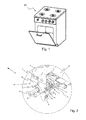
- the object of the present invention is, as in the Figures 2 . 3 . 4, 5 . 6 and 7 shown by means of a valve device with front plate (2) for hobs of stove sets (30) and an advantageous gas valve front plate (2) to solve the problems related to the above object.
- the valve front plate (2) which preferably consists of a metal material, has a front front (14) mounted on the front side of the valve housing (5) of a gas control valve.
- the front plate (2) has a clearance (15) formed in such a way as to frame the valve body (5).
- the clearance (15) becomes, as in FIGS. 4 and 5 shown, preferably defined as a U-shape, which represents a suitable for attachment over a valve housing (5) recess.
- a housing part (23) projects upwards so that here the carriers (23 ) Circulate the housing circular and provide a variety of attachment points available.
- the valve device (30) with its construction described above, in contrast to the front plate (2) a valve housing (5), a control shaft (8), in the receptacle (10) inserted by-pass injector (not shown here), an injector and can carry the valve housing (5) in a stable manner, it has an additional fastening means (9).
- the injector (11) preferably consists of a screw that can be easily adjusted or removed by means of a screwdriver.
- This objective has been achieved by mounting an open hole (4) on the same horizontal axis (X h ) as that of the injector setting (11), allowing a person of normal skill level to adjust the injector setting (11) by using a screwdriver or suitable means ) to adjust or replace the injector. In this way it is possible to change the operating mode of the hob of a stove set in a very practical and easy way to gas bottles or natural gas.
- valve housing (5) is provided with a surface (13) matching the bent tab (3).
- FIG. 4 shows the skeleton of the entire gas burner device of a cooking range of a stove set according to the conventional art, wherein the valve device (30) on the upper left side of the valve device (30) according to the present invention, while the valve device (40) on the right bottom side represents a device according to the prior art.
- the conventional type of valve device (40) does not have an open hole on the same axis with the injector setting device (11) and, as described above, does not provide any additional special aids.
- a prior art valve device (40) may even be disadvantageous considering the hard-to-remove front panel front (41).
- the front plate front (41) according to the prior art, an important part of the L-shaped valve holder profile, which is mounted on a housing part, which in turn in the form of a series of supports (23), the upper level of the housing of the hob Stove Sets (20) rotates. For this reason, a person who wants to reach the gas injector is forced to first take out the entire front panel front (41).
- Another object of the invention is to provide a faceplate which eliminates the need to remove the entire faceplate front.
- This object is achieved with a front plate (2) according to the present invention, which is taken out of the valve holder profile (1) which is attached to a housing part (for example, to the carriers (23) attached to the cooking device (20)).
- the front plate (2) and the valve holder profile (1) are fastened together by a fastening means (7), the fastening means preferably being a screw.
Abstract
Description
Die vorliegende Erfindung ist eine Ventilvorrichtung bezüglich einer gasbetriebenen Kochvorrichtung und betrifft eine Vorderplattenvorrichtung für die Ventile an den Kochfeldern bekannter Herd-Sets, welche ohne Ausbau der Vorrichtung, insbesondere die direkte Erreichbarkeit der inneren Injektionsmodule ermöglicht.The present invention is a valve device relating to a gas powered cooking device and relates to a front plate device for the valves on the hobs of known stove sets, which allows without removing the device, in particular the direct accessibility of the internal injection modules.
Die bekannten gasbetriebenen Kochfelder von Herd-Sets, welche im Allgemeinen einzeln oder auf der oberen Ebene der Kochvorrichtungen im Haushalt verwendet werden, werden entweder mit Gas aus Gasflaschen (Propan/Butan) oder aus dem städtischen Gasnetz (überwiegend Methan) versorgt, wobei in beiden Fällen das Kochfeld des Herd-Sets auf die ausgewählte Gasquelle eingestellt sein muss. Die Kochfeldvorrichtung des Herd-Sets kann entweder passend für den Betrieb mit bekannten Gasflaschen oder passend für die aus den häuslichen Erdgasleitungen zur Verfügung gestellte Versorgung gebaut werden. Aber wenn der Anwender die Kochvorrichtung von der Gasflasche auf Erdgas oder umgekehrt umstellen muss, entsteht ein Änderungsbedarf bei der Betriebsart.The known gas-fired cooktops of cooker sets, which are generally used individually or at the upper level of domestic cooking appliances, are supplied either with gas from gas cylinders (propane / butane) or from the urban gas network (predominantly methane), with both If the hob of the stove set must be set to the selected gas source. The hob kit of the cooker set can either be built to work with known gas cylinders or to suit the supply provided by domestic natural gas pipelines. But if the user has to change the cooking device from the gas cylinder to natural gas or vice versa, there is a need for a change in the operating mode.
Die oben genannte Umstellung wird durch technisches Personal durchgeführt, indem auf die Bypass-Schraube für die Gasinjektion zugegriffen und der Gasinjektor durch einen neuen, der zur gewünschten Betriebsart passt, ausgetauscht wird, oder bestimmte Teile (z.B. der Ventilkontrollknopf nahe der vorderen Metallplatte und die Vorderfläche) entfernt werden.The above changeover is performed by technical personnel by accessing the gas injection bypass screw and replacing the gas injector with a new one that matches the desired mode, or certain parts (eg, the valve control knob near the front metal plate and the front surface ) are removed.
Allerdings hat diese Vorgehensweise viele Nachteile, denn es ist notwendig, dass das technische Personal zeitaufwändige Arbeiten für das Entfernen und Neumontieren der Teile ausführt. Zudem ist es sowohl aus Sicht des Verbrauchers als auch aus Sicht des Herstellers nicht wünschenswert, dass Teile einer neu angeschafften Kochvorrichtung geöffnet werden, weil dieser Vorgang zu weitergehenden Problemen während der Gebrauchsdauer führen kann.However, this approach has many disadvantages, because it is necessary that the technical personnel perform time-consuming work for the removal and re-assembly of the parts. Moreover, from the consumer's point of view as well as the manufacturer's point of view, it is undesirable for parts of a newly purchased cooking device to be desirable be opened because this process can lead to further problems during the period of use.
Ein weiterer Nachteil bei bekannten Kochfeldern von Herd-Sets ist, dass in dem Fall, wenn der Anwender an einem Steuerknopf, der über einen Steuerschaft mit dem Ventil verbunden ist, drehen will, die Ventilvorrichtung meistens dazu neigt, sich um die eigene Achse zu drehen. Die Rotation des Steuerknopfs übt auf die Ventilvorrichtung ein positives Drehmoment aus, was zusammen mit der Bewegung der Steuerknöpfe in Rotationsrichtung dazu führt, dass diese teilweise oder vollständig aus den Verbindungsstellen, an denen sie befestigt sind, losgelöst werden.Another drawback with known cooking ranges of cooker sets is that in the case where the user wishes to rotate on a control knob which is connected to the valve via a control shaft, the valve device tends most often to rotate about its own axis , The rotation of the control knob exerts a positive torque on the valve device, which together with the movement of the control knobs in the direction of rotation causes them to be partially or completely released from the joints to which they are attached.
Die vorliegende Erfindung löst die Probleme bezüglich der oben definierten Aufgabe mit einer Ventilvorrichtung, die wie in Anspruch 1 eine Vorderplatte aufweist.The present invention solves the problems related to the above-defined object with a valve device having a front plate as in
Die vorliegende Erfindung schafft eine Ventilvorrichtung für gasbetriebene Kochvorrichtungen. Der Aufbau der Ventilvorrichtung weist ein Regelventilgehäuse, eine Vorderplatte für die Abstützung und Befestigung des Ventilgehäuses und einen Gasinjektor auf, der hinter der Vorderplatte platziert ist, wobei der Injektor mit einer Injektoreinstellungsvorrichtung verbunden ist, die das Einstellen und Austauschen dieses Injektors ermöglicht, und die Vorderplatte weist eine Vorderfront auf, die an der Vorderseite des Ventilgehäuses angebracht ist und vom Bereich des Gehäuses der Vorrichtung aus in senkrechter Richtung abgeht: hier weist die Vorderplatte zusätzlich an einer Stelle der zugehörigen Vorderfront ein offenes Loch auf, das zum großen Teil mit der Horizontalachse der Injektoreinstellungsvorrichtung übereinstimmt. Die der vorliegenden Erfindung entsprechende Vorderplatte weist zusätzlich in ihrem Aufbau einen Vorsprung auf, der parallel zum Ventilkörpers horizontal abgeht, welcher seinerseits von der Vorderplatte aus senkrecht abgeht, und es befindet sich am Vorsprung eine L-förmige Lasche, wobei die Lasche in Richtung Ventilkörper an diesem anliegend gebogen ist, so dass ihr innerer Freiraum die horizontale Achse so einschließt, dass ein längliches Objekt in Richtung der horizontalen Achse geführt wird.The present invention provides a valve device for gas fired cooking appliances. The structure of the valve device includes a control valve body, a front plate for supporting and fixing the valve body, and a gas injector placed behind the front plate, the injector being connected to an injector setting device which enables setting and replacement of this injector, and the front plate has a front end, which is attached to the front of the valve housing and going off the area of the housing of the device in a vertical direction: here, the front plate in addition to a position of the associated front an open hole, which to a large extent with the horizontal axis of Injector setting device coincides. The front plate according to the present invention additionally has in its construction a projection which extends parallel to the valve body horizontally, which in turn is perpendicular from the front plate, and there is an L-shaped tab on the projection, wherein the tab in the direction of the valve body bent so that their inner space encloses the horizontal axis so that an elongated object is guided in the direction of the horizontal axis.
Die beigefügten Zeichnungen dienen nur dem Zweck der Darstellung einer auf die Erfindung bezogenen Ausführungsform.
-
Figur 1 -
Figur 2 -
Figur 3 -
Figur 4 zeigt die perspektivische Ansicht einer Vorderplattenhaltevorrichtung entsprechend einer bevorzugten Ausführungsform der vorliegenden Erfindung. -
Figur 5 zeigt die Vorderansicht einer Vorderplattenhaltevorrichtung entsprechend einer bevorzugten Ausführungsform der vorliegenden Erfindung. -
Figur 6 zeigt die Seitenansicht einer Vorderplattenhaltevorrichtung entsprechend einer bevorzugten Ausführungsform der vorliegenden Erfindung. -
Figur 7
-
FIG. 1 shows a detailed perspective view of a cooking device according to the present invention. -
FIG. 2 shows a, according to the present invention, a detailed perspective view of the valve device. -
FIG. 3 Fig. 3 is a perspective view showing the entire gas combustion apparatus associated with a conventional hob of a stove set, here the upper side valve apparatus shows the apparatus according to the present invention, and the right side apparatus below is a conventional apparatus, known technique shows. -
FIG. 4 shows the perspective view of a front plate holding device according to a preferred embodiment of the present invention. -
FIG. 5 shows the front view of a front plate holding device according to a preferred embodiment of the present invention. -
FIG. 6 shows the side view of a front plate holding device according to a preferred embodiment of the present invention. -
FIG. 7 shows the top view of a front plate holding device according to a preferred embodiment of the present invention.
Die Aufgabe der vorliegenden Erfindung ist es, wie in den
Damit die Ventilvorrichtung (30) mit ihrer oben beschriebenen Bauweise im Unterschied zur Vorderplatte (2) ein Ventilgehäuse (5), einen Steuerschaft (8), einen in die Aufnahme (10) eingefügten Bypass-Injektor (hier nicht gezeigt), eine Injektoreinstellung und das Ventilgehäuse (5) in stabiler Weise tragen kann, weist sie ein zusätzliches Befestigungsmittel (9) auf. Die Injektoreinstellung (11) besteht bevorzugt aus einer Schraube, die mit Hilfe eines Schraubendrehers auf einfache Weise eingestellt oder herausgenommen werden kann. Eines der oben genannten Probleme, das die vorliegende Erfindung im Hinblick auf die Aufgabe lösen soll, ist, die Injektoreinstellung (11) von der Vorderseite der Ventilvorrichtung (30) her erreichbar zu machen, ohne die Vorderplatte (2) herausnehmen zu müssen. Dieses Ziel wurde durch Anbringen eines offenen Lochs (4) auf der gleichen horizontalen Achse (Xh) wie die der Injektoreinstellung (11) erreicht, was es ermöglicht, dass ein Mensch mit normalen Fertigkeiten durch Verwendung eines Schraubendrehers oder geeigneten Mittels die Injektoreinstellung (11) erreichen kann, um den Injektor einzustellen oder auszutauschen. Auf diese Weise wird es möglich, die Betriebsart des Kochfelds eines Herd-Sets auf sehr praktische und einfache Art auf Gasflaschen oder Erdgas umzustellen.Thus, the valve device (30) with its construction described above, in contrast to the front plate (2) a valve housing (5), a control shaft (8), in the receptacle (10) inserted by-pass injector (not shown here), an injector and can carry the valve housing (5) in a stable manner, it has an additional fastening means (9). The injector (11) preferably consists of a screw that can be easily adjusted or removed by means of a screwdriver. One of the above problems which the present invention is intended to solve in view of the object is to make the injector setting (11) reachable from the front of the valve device (30) without having to take out the front plate (2). This objective has been achieved by mounting an open hole (4) on the same horizontal axis (X h ) as that of the injector setting (11), allowing a person of normal skill level to adjust the injector setting (11) by using a screwdriver or suitable means ) to adjust or replace the injector. In this way it is possible to change the operating mode of the hob of a stove set in a very practical and easy way to gas bottles or natural gas.
Die zur vorliegenden Erfindung gehörige Vorderplatte (2) weist außerdem einen Vorsprung (12) auf, der parallel zur Ausrichtung des Ventilgehäuses (5) horizontal abgeht, wobei dieser Vorsprung (12) zum Großteil senkrecht zur Vorderplatte steht. Im oberen Bereich des Vorsprungs (12) befindet sich eine L-förmige Lasche, die sich in einer Weise in Richtung Ventilgehäuse neigt und sich ihm nähert, dass die innere Aussparung der Lasche, wie oben beschrieben, zum Zwecke der Führung eines länglichen Objekts (z.B. eines Schraubendrehers) die horizontale Achse (Xh) über ihre gesamte Länge hin umschließt. Das zweite Problem, dessen Lösung angestrebt wird, wird durch das L-förmige Neigungsprofil des Vorsprungs (12) gelöst, denn die L-förmige Lasche (3) hat zwei Funktionen.
- a) Zum einen die Funktion, auf einfache Weise die Stabilität des Ventilgehäuses (5) zu erhalten, wenn es durch die Rotation des Steuerschafts (8) um die eigene Achse belastet wird.
- b) Und zum anderen die Funktion, einen Schraubendreher oder einen ähnlichen länglichen Gegenstand, der von einer Person verwendet wird, um den Bypass-Injektor in der Aufnahme (10) einzustellen oder auszutauschen, mit der Injektoreinstellungsvorrichtung (11) zu führen.
- a) On the one hand, the function to easily obtain the stability of the valve housing (5) when it is loaded by the rotation of the control shaft (8) about its own axis.
- b) And second, the function of using a screwdriver or similar elongate object used by a person to set or exchange the bypass injector in the receptacle (10) with the injector setting device (11).
Wenn man die oben beschriebenen Vorteile detailliert durchdenkt, dann ist es klar, dass sich eine Person, die Fachwissen über die Technik von Kochfeldern von Herd-Sets besitzt, über die in Teil a) vorgesehenen Probleme bewusst ist. Um diese Aufgabe zu erfüllen, wird das Ventilgehäuse (5) mit einer zur gebogenen Lasche (3) passenden Fläche (13) versehen.If one thinks through the advantages described above in detail, then it is clear that a person who has expertise in the technique of cooktops of cooker sets is aware of the problems provided in part a). To accomplish this task, the valve housing (5) is provided with a surface (13) matching the bent tab (3).
Ein weiterer Vorteil, der in Teil b) beschrieben wird, ist von der Art, dass er die Vorteile bezüglich des offenen Lochs (4) vervollständigt. Zusätzlich zu den vorteilhaften Auswirkungen des beschriebenen offenen Lochs (4) erfüllt die hier erhaltene Lasche (3) eine Führungsfunktion für das längliche Werkzeug des technischen Personals. Wie auch Personen, die auf technischem Gebiet kompetent sind, erkennen werden, führt die Nichtverwendung einer Führung in der Art, wie sie oben beschrieben wurde, dazu, dass das Werkzeug versehentlich auf irgendein Befestigungsmittel (9) auftreffen kann, wie auf solche (9) in der Nähe der Injektoreinstellungsvorrichtung (11), was dazu führt, dass die sonstigen Befestigungsmittel und die zugehörigen Teile fehlerhaft positioniert werden. Aber entsprechend einer besonderen Ausführungsform der vorliegenden Erfindung nähert eine Person, welche die Injektorteile sachgemäß zu erreichen versucht, ihren Schraubendreher durch die Führung der nach innen gebogenen Lasche (3) an das offene Loch (4) und setzt ihn ohne jedes Problem oder Misserfolg auf die Injektoreinstellungsvorrichtung (11) auf.Another advantage described in part b) is that it completes the advantages with respect to the open hole (4). In addition to the beneficial effects of the described open hole (4), the tab (3) obtained here fulfills a guiding function for the elongated tool of the technical staff. As will be appreciated by those skilled in the art, non-use of a guide in the manner described above will result in the tool accidentally impacting any fastener (9) such as (9) in the vicinity of the Injektoreinstellungsvorrichtung (11), which results in that the other fastening means and the associated parts are positioned incorrectly. However, according to a particular embodiment of the present invention, a person attempting to properly reach the injector parts approximates their screwdriver to the open one by guiding the inwardly bent tab (3) Hole (4) and put him without any problem or failure on the Injektoreinstellungsvorrichtung (11).
Auf diese Weise wird der Vorgang der Umstellung des Kochfelds eines Herd-Sets auf Erdgas oder Gasflaschen erreicht, ohne für das Herausnehmen der Vorderplatte (2), die sich auf der Vorderseite der Ventilvorrichtung (30) befindet, zusätzlichen Aufwand zu betreiben. Wenn man
Eine Ventilvorrichtung (40) nach dem Stand der Technik kann sogar von Nachteil sein, wenn man die schwer zu entfernende Vorderplattenfront (41) betrachtet. Wie in
Eine weitere Aufgabe der Erfindung ist es, eine Vorderplatte zu liefern, die die Entfernung der gesamten Vorderplattenfront unnötig macht. Diese Aufgabe wird erfüllt mit einer Vorderplatte (2) gemäß vorliegender Erfindung, die vom Ventilhalterprofil (1), das an ein Gehäuseteil (z.B. an den an der Kochvorrichtung (20) angebrachten Trägern (23)) befestigt ist, herausgenommen ist. Die Vorderplatte (2) und das Ventilhalterprofil (1) werden durch ein Befestigungsmittel (7) miteinander befestigt, wobei das Befestigungsmittel vorzugsweise eine Schraube ist.Another object of the invention is to provide a faceplate which eliminates the need to remove the entire faceplate front. This object is achieved with a front plate (2) according to the present invention, which is taken out of the valve holder profile (1) which is attached to a housing part (for example, to the carriers (23) attached to the cooking device (20)). The front plate (2) and the valve holder profile (1) are fastened together by a fastening means (7), the fastening means preferably being a screw.
Personen, die auf technischem Gebiet kompetent sind, ist bekannt, dass im Umfang der im Anhang befindlichen Ansprüche noch andere Alternativen und Anwendungen ausgeführt werden können, und es wird angenommen, dass solche Anwendungen, die auch in den Teil der ungebundenen Ansprüche aufgenommen wurden, ohne vom Umfang der Erfindung und seines Wesens abzuweichen, umgesetzt werden.Persons who are competent in the technical field are aware of other alternatives and applications within the scope of the appended claims and it is believed that such applications, which are also included in the scope of the independent claims, without departing from the scope of the invention and its essence, be implemented.
- 1 -1 -
- VentilhalterprofilValve holder profile
- 2 -2 -
- Vorderplatte GasventilFront plate gas valve
- 3 -3 -
- Lascheflap
- 4 -4 -
- offenes Lochopen hole
- 5 -5 -
- Gehäusecasing
- xh -x h -
- HorizontalachseHorizontal axis
- 7-7-
- Befestigungsmittelfastener
- 8 -8th -
- Steuerschaftcontrol shaft
- 9 -9 -
- Befestigungsmittelfastener
- 10 -10 -
- Aufnahmeadmission
- 11 -11 -
- InjektoreinstellungsvorrichtungInjektoreinstellungsvorrichtung
- 12 -12 -
- Vorsprunghead Start
- 13 -13 -
- Frontflächefront surface
- 14 -14 -
- Vorderfrontfront
- 15 -15 -
- Freiraumfree space
- 20 -20 -
- Kochvorrichtungcooking apparatus
- 23 -23 -
- Gehäuseteil (z.B. Träger)Housing part (e.g., carrier)
- 30 -30 -
- Ventilvorrichtung für das Kochfeld eines Herd-SetsValve device for the hob of a stove set
- 40 -40 -
- Ventilvorrichtung nach herkömmlicher TechnikValve device according to conventional technology
- 41 -41 -
- VorderplattenfrontFront panel Front
- 50 -50 -
- Steuerknopfcontrol knob
- 60 -60 -
- Brennerburner
Claims (8)
ein Gasregelventilgehäuse (5)
eine Vorderplatte (2), die der Stützung und Befestigung des Ventilgehäuses (5) dient, wobei die Vorderplatte (2) eine Vorderfront (14) aufweist, die an der Vorderseite des Ventilgehäuses (5) angebracht ist, und
einen Gasinjektor, der eine an der Rückseite der Platte (2) angebrachte Einstellungsvorrichtung (11) aufweist, dadurch gekennzeichnet, dass sie zusätzlich an einer Stelle der Vorderfront (14) der Vorderplatte (2) ein offenes Loch aufweist, das mit der horizontalen Achse (xh) der Injektoreinstellung (11) übereinstimmt.Valve device for a gas fired cooking device (20) containing the elements below
a gas control valve housing (5)
a front plate (2) for supporting and fixing the valve housing (5), the front plate (2) having a front face (14) attached to the front of the valve housing (5), and
a gas injector having a setting device (11) attached to the back of the plate (2), characterized in that it additionally has an open hole at a position of the front face (14) of the front plate (2) which is aligned with the horizontal axis (Fig. x h ) of the injector (11) matches.
Applications Claiming Priority (1)
| Application Number | Priority Date | Filing Date | Title |
|---|---|---|---|
| TR200910043 | 2009-12-31 |
Publications (2)
| Publication Number | Publication Date |
|---|---|
| EP2341289A1 true EP2341289A1 (en) | 2011-07-06 |
| EP2341289B1 EP2341289B1 (en) | 2017-04-05 |
Family
ID=43828268
Family Applications (1)
| Application Number | Title | Priority Date | Filing Date |
|---|---|---|---|
| EP10194250.6A Active EP2341289B1 (en) | 2009-12-31 | 2010-12-09 | Valve device for a gas-operated cooking device |
Country Status (1)
| Country | Link |
|---|---|
| EP (1) | EP2341289B1 (en) |
Citations (5)
| Publication number | Priority date | Publication date | Assignee | Title |
|---|---|---|---|---|
| FR1264994A (en) * | 1960-08-12 | 1961-06-23 | Robertshaw Fulton Controls Co | Device for regulating the supply of fuel to the burners |
| FR1339211A (en) * | 1962-11-14 | 1963-10-04 | In Nome Coll Di Libero Balestr | Improvements to gas stove taps with gas flow adjustment from the rear |
| US3125293A (en) * | 1964-03-17 | burdett | ||
| DE2155863A1 (en) * | 1971-08-28 | 1973-06-14 | Niederscheld Gmbh Armaturwerk | ARRANGEMENT OF THE REGULATORY BODIES FOR GAS ACCESS TO THE INDIVIDUAL BURNERS OF A GAS COOKER |
| US4813596A (en) * | 1988-05-10 | 1989-03-21 | Robertshaw Controls Company | Fuel control device, fuel control system using the device and method of making the device |
Family Cites Families (1)
| Publication number | Priority date | Publication date | Assignee | Title |
|---|---|---|---|---|
| GB944286A (en) * | 1959-04-11 | 1963-12-11 | Cannon Ind Ltd | Improvements relating to gas burners of cooker hotplates |
-
2010
- 2010-12-09 EP EP10194250.6A patent/EP2341289B1/en active Active
Patent Citations (5)
| Publication number | Priority date | Publication date | Assignee | Title |
|---|---|---|---|---|
| US3125293A (en) * | 1964-03-17 | burdett | ||
| FR1264994A (en) * | 1960-08-12 | 1961-06-23 | Robertshaw Fulton Controls Co | Device for regulating the supply of fuel to the burners |
| FR1339211A (en) * | 1962-11-14 | 1963-10-04 | In Nome Coll Di Libero Balestr | Improvements to gas stove taps with gas flow adjustment from the rear |
| DE2155863A1 (en) * | 1971-08-28 | 1973-06-14 | Niederscheld Gmbh Armaturwerk | ARRANGEMENT OF THE REGULATORY BODIES FOR GAS ACCESS TO THE INDIVIDUAL BURNERS OF A GAS COOKER |
| US4813596A (en) * | 1988-05-10 | 1989-03-21 | Robertshaw Controls Company | Fuel control device, fuel control system using the device and method of making the device |
Also Published As
| Publication number | Publication date |
|---|---|
| EP2341289B1 (en) | 2017-04-05 |
Similar Documents
| Publication | Publication Date | Title |
|---|---|---|
| EP0107162B1 (en) | Work table | |
| EP1697608B1 (en) | Housing for a household appliance | |
| DE102009046833A1 (en) | fastener | |
| DE2127677A1 (en) | Device for adjusting the height of the nozzle in vacuum cleaners | |
| EP2341289B1 (en) | Valve device for a gas-operated cooking device | |
| EP0962723B1 (en) | Wall mounted technical domestic installation | |
| DE2908089A1 (en) | PERMANENT CALENDAR | |
| DE102009000650A1 (en) | Household appliance i.e. baking oven, has locking element arranged between front part and housing, and engaging element locked in locking element and arranged for adjusting front part opposite to front surface | |
| EP1125534B1 (en) | Cooking system having a tube construction | |
| DE2205401B1 (en) | PORTABLE AND COLLAPSIBLE GRILL | |
| DE202012100493U1 (en) | Furniture with a box-shaped furniture body and attached screen mount | |
| DE2506594C2 (en) | DEVICE FOR MICROSCOPIC VIEWING, IN PARTICULAR FOR PATTERNING GEMSTONES | |
| DE2633914A1 (en) | Right and left hand mounted door - has pivoted hinge sleeve on serrated fitting plate on door panel | |
| DE3244681C2 (en) | ||
| EP1318357B1 (en) | Flow rate controller | |
| DE3135082C2 (en) | "Device for fastening motor vehicle parts during assembly and / or repair work" | |
| EP3228218B1 (en) | Furniture element | |
| DE202006003553U1 (en) | Portable heater with a burner head | |
| EP2341291A2 (en) | Fixing plate for fixing a gas valve to a gas conduit | |
| DE847800C (en) | Cabinet for hanging drawings, plans or the like. | |
| DE102011055655A1 (en) | Housing for medium supplier, has housing body, in which fixing section is formed for attachment of media supply elements | |
| DE202023002441U1 (en) | Cooking attachment for an indoor fireplace of a high-light lantern | |
| DE2551230B2 (en) | ADJUSTABLE HANDLE FOR ONE HOUSING | |
| DE1381787U (en) | ||
| WO1992013149A1 (en) | Partitioning system |
Legal Events
| Date | Code | Title | Description |
|---|---|---|---|
| PUAI | Public reference made under article 153(3) epc to a published international application that has entered the european phase |
Free format text: ORIGINAL CODE: 0009012 |
|
| AK | Designated contracting states |
Kind code of ref document: A1 Designated state(s): AL AT BE BG CH CY CZ DE DK EE ES FI FR GB GR HR HU IE IS IT LI LT LU LV MC MK MT NL NO PL PT RO RS SE SI SK SM TR |
|
| AX | Request for extension of the european patent |
Extension state: BA ME |
|
| 17P | Request for examination filed |
Effective date: 20120109 |
|
| 17Q | First examination report despatched |
Effective date: 20131119 |
|
| RAP1 | Party data changed (applicant data changed or rights of an application transferred) |
Owner name: BSH HAUSGERAETE GMBH |
|
| RIC1 | Information provided on ipc code assigned before grant |
Ipc: F23N 1/00 20060101ALI20161003BHEP Ipc: F23N 5/26 20060101ALI20161003BHEP Ipc: F24C 3/12 20060101AFI20161003BHEP |
|
| GRAP | Despatch of communication of intention to grant a patent |
Free format text: ORIGINAL CODE: EPIDOSNIGR1 |
|
| INTG | Intention to grant announced |
Effective date: 20161123 |
|
| GRAS | Grant fee paid |
Free format text: ORIGINAL CODE: EPIDOSNIGR3 |
|
| GRAA | (expected) grant |
Free format text: ORIGINAL CODE: 0009210 |
|
| AK | Designated contracting states |
Kind code of ref document: B1 Designated state(s): AL AT BE BG CH CY CZ DE DK EE ES FI FR GB GR HR HU IE IS IT LI LT LU LV MC MK MT NL NO PL PT RO RS SE SI SK SM TR |
|
| REG | Reference to a national code |
Ref country code: GB Ref legal event code: FG4D Free format text: NOT ENGLISH |
|
| REG | Reference to a national code |
Ref country code: CH Ref legal event code: EP |
|
| REG | Reference to a national code |
Ref country code: AT Ref legal event code: REF Ref document number: 882184 Country of ref document: AT Kind code of ref document: T Effective date: 20170415 |
|
| REG | Reference to a national code |
Ref country code: IE Ref legal event code: FG4D Free format text: LANGUAGE OF EP DOCUMENT: GERMAN |
|
| REG | Reference to a national code |
Ref country code: DE Ref legal event code: R096 Ref document number: 502010013421 Country of ref document: DE |
|
| REG | Reference to a national code |
Ref country code: NL Ref legal event code: MP Effective date: 20170405 |
|
| REG | Reference to a national code |
Ref country code: LT Ref legal event code: MG4D |
|
| PG25 | Lapsed in a contracting state [announced via postgrant information from national office to epo] |
Ref country code: NL Free format text: LAPSE BECAUSE OF FAILURE TO SUBMIT A TRANSLATION OF THE DESCRIPTION OR TO PAY THE FEE WITHIN THE PRESCRIBED TIME-LIMIT Effective date: 20170405 |
|
| PG25 | Lapsed in a contracting state [announced via postgrant information from national office to epo] |
Ref country code: FI Free format text: LAPSE BECAUSE OF FAILURE TO SUBMIT A TRANSLATION OF THE DESCRIPTION OR TO PAY THE FEE WITHIN THE PRESCRIBED TIME-LIMIT Effective date: 20170405 Ref country code: NO Free format text: LAPSE BECAUSE OF FAILURE TO SUBMIT A TRANSLATION OF THE DESCRIPTION OR TO PAY THE FEE WITHIN THE PRESCRIBED TIME-LIMIT Effective date: 20170705 Ref country code: ES Free format text: LAPSE BECAUSE OF FAILURE TO SUBMIT A TRANSLATION OF THE DESCRIPTION OR TO PAY THE FEE WITHIN THE PRESCRIBED TIME-LIMIT Effective date: 20170405 Ref country code: HR Free format text: LAPSE BECAUSE OF FAILURE TO SUBMIT A TRANSLATION OF THE DESCRIPTION OR TO PAY THE FEE WITHIN THE PRESCRIBED TIME-LIMIT Effective date: 20170405 Ref country code: LT Free format text: LAPSE BECAUSE OF FAILURE TO SUBMIT A TRANSLATION OF THE DESCRIPTION OR TO PAY THE FEE WITHIN THE PRESCRIBED TIME-LIMIT Effective date: 20170405 Ref country code: GR Free format text: LAPSE BECAUSE OF FAILURE TO SUBMIT A TRANSLATION OF THE DESCRIPTION OR TO PAY THE FEE WITHIN THE PRESCRIBED TIME-LIMIT Effective date: 20170706 |
|
| PG25 | Lapsed in a contracting state [announced via postgrant information from national office to epo] |
Ref country code: BG Free format text: LAPSE BECAUSE OF FAILURE TO SUBMIT A TRANSLATION OF THE DESCRIPTION OR TO PAY THE FEE WITHIN THE PRESCRIBED TIME-LIMIT Effective date: 20170705 Ref country code: LV Free format text: LAPSE BECAUSE OF FAILURE TO SUBMIT A TRANSLATION OF THE DESCRIPTION OR TO PAY THE FEE WITHIN THE PRESCRIBED TIME-LIMIT Effective date: 20170405 Ref country code: PL Free format text: LAPSE BECAUSE OF FAILURE TO SUBMIT A TRANSLATION OF THE DESCRIPTION OR TO PAY THE FEE WITHIN THE PRESCRIBED TIME-LIMIT Effective date: 20170405 Ref country code: SE Free format text: LAPSE BECAUSE OF FAILURE TO SUBMIT A TRANSLATION OF THE DESCRIPTION OR TO PAY THE FEE WITHIN THE PRESCRIBED TIME-LIMIT Effective date: 20170405 Ref country code: IS Free format text: LAPSE BECAUSE OF FAILURE TO SUBMIT A TRANSLATION OF THE DESCRIPTION OR TO PAY THE FEE WITHIN THE PRESCRIBED TIME-LIMIT Effective date: 20170805 Ref country code: RS Free format text: LAPSE BECAUSE OF FAILURE TO SUBMIT A TRANSLATION OF THE DESCRIPTION OR TO PAY THE FEE WITHIN THE PRESCRIBED TIME-LIMIT Effective date: 20170405 |
|
| REG | Reference to a national code |
Ref country code: DE Ref legal event code: R097 Ref document number: 502010013421 Country of ref document: DE |
|
| PG25 | Lapsed in a contracting state [announced via postgrant information from national office to epo] |
Ref country code: CZ Free format text: LAPSE BECAUSE OF FAILURE TO SUBMIT A TRANSLATION OF THE DESCRIPTION OR TO PAY THE FEE WITHIN THE PRESCRIBED TIME-LIMIT Effective date: 20170405 Ref country code: SK Free format text: LAPSE BECAUSE OF FAILURE TO SUBMIT A TRANSLATION OF THE DESCRIPTION OR TO PAY THE FEE WITHIN THE PRESCRIBED TIME-LIMIT Effective date: 20170405 Ref country code: RO Free format text: LAPSE BECAUSE OF FAILURE TO SUBMIT A TRANSLATION OF THE DESCRIPTION OR TO PAY THE FEE WITHIN THE PRESCRIBED TIME-LIMIT Effective date: 20170405 Ref country code: EE Free format text: LAPSE BECAUSE OF FAILURE TO SUBMIT A TRANSLATION OF THE DESCRIPTION OR TO PAY THE FEE WITHIN THE PRESCRIBED TIME-LIMIT Effective date: 20170405 Ref country code: DK Free format text: LAPSE BECAUSE OF FAILURE TO SUBMIT A TRANSLATION OF THE DESCRIPTION OR TO PAY THE FEE WITHIN THE PRESCRIBED TIME-LIMIT Effective date: 20170405 |
|
| PLBE | No opposition filed within time limit |
Free format text: ORIGINAL CODE: 0009261 |
|
| STAA | Information on the status of an ep patent application or granted ep patent |
Free format text: STATUS: NO OPPOSITION FILED WITHIN TIME LIMIT |
|
| PG25 | Lapsed in a contracting state [announced via postgrant information from national office to epo] |
Ref country code: IT Free format text: LAPSE BECAUSE OF FAILURE TO SUBMIT A TRANSLATION OF THE DESCRIPTION OR TO PAY THE FEE WITHIN THE PRESCRIBED TIME-LIMIT Effective date: 20170405 Ref country code: SM Free format text: LAPSE BECAUSE OF FAILURE TO SUBMIT A TRANSLATION OF THE DESCRIPTION OR TO PAY THE FEE WITHIN THE PRESCRIBED TIME-LIMIT Effective date: 20170405 |
|
| 26N | No opposition filed |
Effective date: 20180108 |
|
| PG25 | Lapsed in a contracting state [announced via postgrant information from national office to epo] |
Ref country code: SI Free format text: LAPSE BECAUSE OF FAILURE TO SUBMIT A TRANSLATION OF THE DESCRIPTION OR TO PAY THE FEE WITHIN THE PRESCRIBED TIME-LIMIT Effective date: 20170405 |
|
| REG | Reference to a national code |
Ref country code: DE Ref legal event code: R119 Ref document number: 502010013421 Country of ref document: DE |
|
| REG | Reference to a national code |
Ref country code: CH Ref legal event code: PL |
|
| GBPC | Gb: european patent ceased through non-payment of renewal fee |
Effective date: 20171209 |
|
| REG | Reference to a national code |
Ref country code: IE Ref legal event code: MM4A |
|
| PG25 | Lapsed in a contracting state [announced via postgrant information from national office to epo] |
Ref country code: MT Free format text: LAPSE BECAUSE OF FAILURE TO SUBMIT A TRANSLATION OF THE DESCRIPTION OR TO PAY THE FEE WITHIN THE PRESCRIBED TIME-LIMIT Effective date: 20170405 Ref country code: LU Free format text: LAPSE BECAUSE OF NON-PAYMENT OF DUE FEES Effective date: 20171209 |
|
| REG | Reference to a national code |
Ref country code: FR Ref legal event code: ST Effective date: 20180831 |
|
| REG | Reference to a national code |
Ref country code: BE Ref legal event code: MM Effective date: 20171231 |
|
| PG25 | Lapsed in a contracting state [announced via postgrant information from national office to epo] |
Ref country code: IE Free format text: LAPSE BECAUSE OF NON-PAYMENT OF DUE FEES Effective date: 20171209 Ref country code: FR Free format text: LAPSE BECAUSE OF NON-PAYMENT OF DUE FEES Effective date: 20180102 Ref country code: DE Free format text: LAPSE BECAUSE OF NON-PAYMENT OF DUE FEES Effective date: 20180703 |
|
| PG25 | Lapsed in a contracting state [announced via postgrant information from national office to epo] |
Ref country code: BE Free format text: LAPSE BECAUSE OF NON-PAYMENT OF DUE FEES Effective date: 20171231 Ref country code: GB Free format text: LAPSE BECAUSE OF NON-PAYMENT OF DUE FEES Effective date: 20171209 Ref country code: CH Free format text: LAPSE BECAUSE OF NON-PAYMENT OF DUE FEES Effective date: 20171231 Ref country code: LI Free format text: LAPSE BECAUSE OF NON-PAYMENT OF DUE FEES Effective date: 20171231 |
|
| REG | Reference to a national code |
Ref country code: AT Ref legal event code: MM01 Ref document number: 882184 Country of ref document: AT Kind code of ref document: T Effective date: 20171209 |
|
| PG25 | Lapsed in a contracting state [announced via postgrant information from national office to epo] |
Ref country code: AT Free format text: LAPSE BECAUSE OF NON-PAYMENT OF DUE FEES Effective date: 20171209 |
|
| PG25 | Lapsed in a contracting state [announced via postgrant information from national office to epo] |
Ref country code: HU Free format text: LAPSE BECAUSE OF FAILURE TO SUBMIT A TRANSLATION OF THE DESCRIPTION OR TO PAY THE FEE WITHIN THE PRESCRIBED TIME-LIMIT; INVALID AB INITIO Effective date: 20101209 Ref country code: MC Free format text: LAPSE BECAUSE OF FAILURE TO SUBMIT A TRANSLATION OF THE DESCRIPTION OR TO PAY THE FEE WITHIN THE PRESCRIBED TIME-LIMIT Effective date: 20170405 |
|
| PG25 | Lapsed in a contracting state [announced via postgrant information from national office to epo] |
Ref country code: CY Free format text: LAPSE BECAUSE OF NON-PAYMENT OF DUE FEES Effective date: 20170405 |
|
| PG25 | Lapsed in a contracting state [announced via postgrant information from national office to epo] |
Ref country code: MK Free format text: LAPSE BECAUSE OF FAILURE TO SUBMIT A TRANSLATION OF THE DESCRIPTION OR TO PAY THE FEE WITHIN THE PRESCRIBED TIME-LIMIT Effective date: 20170405 |
|
| PG25 | Lapsed in a contracting state [announced via postgrant information from national office to epo] |
Ref country code: PT Free format text: LAPSE BECAUSE OF FAILURE TO SUBMIT A TRANSLATION OF THE DESCRIPTION OR TO PAY THE FEE WITHIN THE PRESCRIBED TIME-LIMIT Effective date: 20170405 |
|
| PG25 | Lapsed in a contracting state [announced via postgrant information from national office to epo] |
Ref country code: AL Free format text: LAPSE BECAUSE OF FAILURE TO SUBMIT A TRANSLATION OF THE DESCRIPTION OR TO PAY THE FEE WITHIN THE PRESCRIBED TIME-LIMIT Effective date: 20170405 |
|
| PGFP | Annual fee paid to national office [announced via postgrant information from national office to epo] |
Ref country code: TR Payment date: 20231201 Year of fee payment: 14 |