EP2341271B2 - Axialpressfitting - Google Patents
Axialpressfitting Download PDFInfo
- Publication number
- EP2341271B2 EP2341271B2 EP10195099.6A EP10195099A EP2341271B2 EP 2341271 B2 EP2341271 B2 EP 2341271B2 EP 10195099 A EP10195099 A EP 10195099A EP 2341271 B2 EP2341271 B2 EP 2341271B2
- Authority
- EP
- European Patent Office
- Prior art keywords
- pipe
- attachment ring
- arrangement according
- tube
- press fitting
- Prior art date
- Legal status (The legal status is an assumption and is not a legal conclusion. Google has not performed a legal analysis and makes no representation as to the accuracy of the status listed.)
- Active
Links
Images



Classifications
-
- F—MECHANICAL ENGINEERING; LIGHTING; HEATING; WEAPONS; BLASTING
- F16—ENGINEERING ELEMENTS AND UNITS; GENERAL MEASURES FOR PRODUCING AND MAINTAINING EFFECTIVE FUNCTIONING OF MACHINES OR INSTALLATIONS; THERMAL INSULATION IN GENERAL
- F16L—PIPES; JOINTS OR FITTINGS FOR PIPES; SUPPORTS FOR PIPES, CABLES OR PROTECTIVE TUBING; MEANS FOR THERMAL INSULATION IN GENERAL
- F16L13/00—Non-disconnectable pipe joints, e.g. soldered, adhesive, or caulked joints
- F16L13/14—Non-disconnectable pipe joints, e.g. soldered, adhesive, or caulked joints made by plastically deforming the material of the pipe, e.g. by flanging, rolling
- F16L13/146—Non-disconnectable pipe joints, e.g. soldered, adhesive, or caulked joints made by plastically deforming the material of the pipe, e.g. by flanging, rolling by an axially moveable sleeve
Definitions
- the invention relates to an axial press fitting with at least one pipe connecting piece extending along a longitudinal axis, which has a front end designed for insertion into a pipe and a rear end with a collar-like attachment element for pressing pliers, which extends essentially transversely to the longitudinal axis of the connecting piece and around which a pressing tongs can be applied to press a sliding sleeve placed on the pipe.
- a medium-tight connection with the pipe is realized during the pressing process.
- the pipe has an end that is widened for inserting the pipe socket, and the sliding sleeve that has been put on rests directly on the pipe.
- Axial press fittings are designed, for example, as a forged part, as a cast part or preferably also as a plastic injection molded part and are known in practice in many different designs, for example as a simple cylindrical component for extending or connecting pipelines in order to connect two sections of the same pipeline with one another or also, for example, as a T -shaped or Y-shaped branch component.
- the pipe sockets that such a fitting can have can either be used to be inserted into the end of a pipeline.
- Axial press fittings are also known as sliding sleeve systems.
- the shoring or the connection to the pipe usually takes place as follows: First, the sliding sleeve is pushed onto the free end of a pipe, which is preferably designed as a composite pipe. The free end of the pipe is then widened so that it can be pushed onto the pipe socket of the axial press fitting.
- the pipe socket preferably has a plurality of sawtooth-like projections which are arranged spaced apart from one another along the longitudinal axis and protrude radially from the outer lateral surface, which in the installed position are pressed into the inner wall of the pipe.
- the front end of the tube is pushed as far as possible against the attachment element, which is designed as a radially circumferential collar.
- Pressing pliers are then placed on the axial press fitting in such a way that the first pliers member engages against the attachment element, which is often also referred to as a press collar, and the second pliers member engages behind the sliding sleeve at the ends facing away from one another.
- the sliding sleeve is then pushed axially towards the end of the pipe onto the attachment element until the front end of the sliding sleeve rests against the attachment element.
- the sliding sleeve is pushed onto the pipe, the media-tight connection between the connecting piece and the inside of the pipe is established and the pipe is captive and media-tight on the axial press fitting in the installation position.
- radial press fittings are known, in which case an exclusively radially inwardly directed force is exerted on a deformable press sleeve by means of press pliers.
- radial press fittings are out DE 298 12 222 U1 and DE 297 00 666 U1 famous.
- non-generic fittings with complex double sleeves are also known in which a radial force is exerted on the pipe by axially sliding an outer sleeve, which does not bear directly against the pipe to be connected, onto an inner sleeve.
- Such fittings are out EP 2 093 469 A2 and EP 1 288 554 A1 famous.
- the attachment element or the press collar determines the size of the component and the amount of material required for production to a considerable extent.
- the attachment element is the component that absorbs the main forces of the pressing tongs that occur during pressing.
- shear forces occur, but also very considerable bending forces at the connection of the extension element with the wall of the axial press fitting, which ultimately lead to the wall or lateral surface of the axial press fitting having to be made much thicker or stronger than would be required for normal operation , whereby actually only small forces act on the component.
- the attachment element representing an accumulation of material cools down significantly more slowly than the cylindrical lateral surface of the pipe socket or the rest of the fitting. This or the formation of cavities can cause residual stresses in the component and thus have a negative impact on the mechanical properties. In general, accumulations of material are problematic for all components, but especially for plastic parts, because they cool down more slowly and therefore have a negative impact on the process cycles. On the other hand, you need the wall thickness of the attachment element for stability as the force application point for the pressing pliers, especially with plastic injection molded parts.
- Axial press fittings designed as plastic injection molded parts are preferably made from PPSU, which is also approved for use in the drinking water sector.
- PPSU has relatively poor mechanical properties, so that the attachment element and the pipe socket and consequently also its wall must be made significantly thicker in order to be able to absorb the forces occurring during pressing.
- PPSU also has to be injected at around 400° Celsius, which means relatively long cycle times for cooling.
- controlled cooling is absolutely necessary to avoid the aforementioned internal stresses in the component.
- the curing process essentially determines the cycle time during production.
- An axial press fitting according to the preamble of claim 1 is from DE-A-101 30 003 famous.
- the invention is based on the object of at least partially avoiding these disadvantages and developing a generic axial press fitting in such a way that the product quality is improved and the cycle times for production are reduced.
- the object is achieved by an axial press fitting, with at least one pipe socket, with a pipe that has a flared end for inserting the pipe socket, and with a sliding sleeve that is placed on the pipe and rests directly on the pipe, with the at least one pipe socket extends along a longitudinal axis and is designed at a front end for insertion into the pipe and has a rear end with an attachment element for a pressing tongs, around which the pressing tongs can be applied in a gripping manner for pressing the sliding sleeve placed on the pipe against the attachment element under media-tight conditions Enclosure of the tube, wherein the attachment element is formed as a separate mounting ring and wherein connection means are provided between the tube socket and the mounting ring.
- the surprising advantage of the proposed solution is that the separate attachment ring almost completely absorbs the bending forces that occur during pressing without transferring them to the axial press fitting. Due to the proposed design, the wall thickness of the outer surface of the pipe socket can be reduced by up to 60% to the minimum required wall thickness, which significantly improves the zeta value and has an advantageous effect on the flow properties. Since the attachment ring can also be manufactured separately, this and its amount of material no longer decisively determine the cycle time in the manufacture of the axial press fitting.
- the connecting means between the pipe socket and the attachment ring are preferably formed at the rear end of the pipe socket.
- the connecting means comprise a projection formed between the corresponding components, preferably an integrally formed stop which is particularly preferably formed on the outer lateral surface of the pipe socket and against which the attachment ring rests during pressing.
- An alternative embodiment provides a bead in one of the two components, into which a projection of the other component engages in a latching manner in order to absorb the forces during pressing.
- the connecting means on the components comprise correspondingly designed threaded elements.
- the design according to the invention now also makes it possible for the first time to construct the attachment ring from a different material than the pipe socket, in particular a material which has improved mechanical properties compared to the material of the pipe socket for absorbing the forces occurring during pressing.
- the attachment ring can be made of a glass fiber reinforced polyamide.
- the water-carrying connecting piece is made of PPSU and the attachment ring can be made of the glass-fibre reinforced plastic that has the improved mechanical properties.
- the attachment ring can be made much more filigree than if it were also made of PPSU.
- glass fiber reinforced polyamide is significantly cheaper than PPSU, which is approved for the food sector.
- the design according to the invention reduces the material costs by up to 50%.
- the outer diameter of the press collar can be reduced by about half compared to the design made of PPSU due to the separate design of the attachment ring on glass fiber reinforced plastic. Since the attachment ring does not come into contact with the drinking water medium, materials can be used that do not have drinking water approval. Glass fiber reinforced plastics in particular, which are suitable for this application due to their mechanical properties, usually cannot be used in drinking water due to the risk of fiber washing out. In addition, there are considerable cost advantages, since suitable plastics without drinking water approval are approx. 80 - 90% cheaper than PPSU.
- Existing tools in particular the pressing pliers, can also be used for pressing the axial press fitting according to the invention without reconfiguration. For example, they can still be placed on both sides from the left or right.
- the design according to the invention is particularly suitable for axial press fittings of larger dimensions, because in the prior art, due to their relative size, they require a particularly large amount of material for the production of the press collar and thus significantly determine the cycle times.
- the design according to the invention is therefore particularly suitable for external pipe diameters of 14-20 mm, but also up to 40 mm, and in individual cases even up to an external diameter of 63 mm.
- the attachment ring can also be designed so that it can be placed on the fitting, e.g. as a divided attachment ring with a U-shape, for example, or as a snap ring.
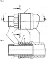
- the axial press fitting 2 consists essentially of a circular-cylindrical hollow body with a constant wall thickness, which has pipe sockets 4 at its outer ends.
- the pipe socket 4 has a sawtooth structure 8 formed in a known manner and formed in one piece, which forms a medium-tight connection with the composite pipe 12 pushed onto the pipe socket 4 when pressed.
- a circular sliding sleeve 16 which has a slightly larger inner diameter than the composite pipe 12, is pushed onto the flared end of the composite pipe.
- This pushing on referred to as “pressing” is realized by means of a known and not shown pressing pliers, which has two jaws, of which a first grips the rear side of the sliding sleeves 16 facing away from the pipe socket and the second grips the rear side of an attachment ring 18 facing away from the pipe socket 4 .
- the press collar which usually protrudes far radially outwards in the prior art, is replaced by the annular attachment ring 18, which consists of glass fiber reinforced plastic and is snapped onto the fitting 2 and fixed in a groove.
- the attachment ring 18 bears against a projection 22 which protrudes radially from the lateral surface of the fitting 2 and is formed in one piece and adjoins the section with the sawtooth structure 8 . Since this projection 22 actually only has to absorb the shearing forces occurring during pressing and no bending stresses, it can be made significantly smaller than the press collars known from the prior art. A reduction in size of up to 60% or more can usually be achieved.
- the illustrated first embodiment of the proposed axial press fitting 2 is characterized by an attachment ring 18, which has the shape of a one-piece closed circular ring and whose inner diameter is just large enough that it can be pushed onto the fitting 2 from the rear until it is in the circumferential Groove in the outer surface of the fitting 2 against the projection 22 rests.
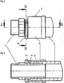
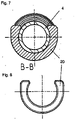
- the attachment ring 20 is not closed, but is designed as a U-shaped snap element with a slight undercut in the central opening, which can be snapped onto the circumferential groove of the fitting 2 to rest against the projection 22 .
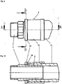
- the illustrated third embodiment of the proposed axial press fitting 2 includes an attachment ring 24 which has an internal thread 26 on its inside, which can be placed on a correspondingly designed threaded section of the fitting 2 with a correspondingly designed external thread 28 . Accordingly, this embodiment does not require a projection 22 for the attachment of the attachment ring 24 on the fitting 2.
- the attachment ring 30 is divisible, consisting of an in 15 semicircular element 30a on the left-hand side and a second semicircular element 26b arranged on the right-hand side, which can be captively connected to one another by twisting via conically interlocking tongue and groove connections in the connection position.
- This embodiment is particularly easy to assemble.
- the attachment rings can also be produced using the 2K injection molding process.
- the proposed design is not only limited to one embodiment of the fitting 2 shown in the figures, but can also be used for branch pieces of any type, that is to say with a plurality of pipe sockets 4 .
- the invention also extends to such embodiments that connect tubes of different geometries to one another.
Landscapes
- Engineering & Computer Science (AREA)
- General Engineering & Computer Science (AREA)
- Mechanical Engineering (AREA)
- Mutual Connection Of Rods And Tubes (AREA)
Description
- Die Erfindung betrifft ein Axialpressfitting mit mindestens einem sich entlang einer Längsachse erstreckenden Rohrstutzen, der ein zum Einsetzen in ein Rohr ausgebildetes Vorderende und ein Hinterende mit einem kragenartigen Ansatzelement für eine Presszange aufweist, welches sich im Wesentlichen quer zu der Längsachse des Anschlussstutzens erstreckt und um welche eine Presszange umgreifend angesetzt werden kann zum Verpressen einer auf das Rohr aufgesetzten Schieberhülse. Beim Verpressen wird eine mediendichte Verbindung mit dem Rohr realisiert. Das Rohr weist ein zum Einsetzen des Rohrstutzens aufgeweitetes Ende auf und die aufgesetzte Schieberhülse liegt direkt an dem Rohr an.
- Axialpressfittings sind zum Beispiel als Schmiedeteil, als Gussteil oder vorzugsweise auch als Kunststoffspritzgussteil ausgebildet und sind in der Praxis in vielfältigen Ausführungen bekannt, beispielsweise als einfaches zylindrisches Bauteil zur Verlängerung oder Verbindung von Rohrleitungen, um zwei Abschnitte derselben Rohrleitung miteinander zu verbinden oder auch beispielsweise als T-förmiges oder Y-förmiges Abzweigbauteil.
- Die Rohrstutzen, die ein derartiges Fitting aufweisen kann, können entweder dazu dienen, in das Ende einer Rohrleitung eingesteckt zu werden.
- Axialpressfittings werden auch als Schieberhülsensystem bezeichnet. Der Verbau oder die Verbindung mit dem Rohr erfolgt üblicherweise folgendermaßen: Zunächst wird die Schieberhülse auf das freie Ende eines Rohres aufgeschoben, das vorzugsweise als Verbundrohr ausgebildet ist. Sodann wird das freie Ende des Rohres aufgeweitet, so dass dieses auf den Rohrstutzen des Axialpressfittings aufschiebbar ist. Der Rohrstutzen weist dazu vorzugsweise mehrere entlang der Längsachse beabstandet zueinander angeordnete sägezahnartige radial von der äußeren Mantelfläche abragende Vorsprünge auf, welche sich in Einbaulage in die Innenwand des Rohres pressen. Das Stirnende des Rohres wird möglichst gegen das als radial umlaufender Kragen ausgebildete.. Ansatzelement geschoben. Sodann wird eine Presszange so auf das Axialpressfitting aufgesetzt, so dass das erste Zangenglied gegen das häufig auch als Presskragen bezeichnete Ansatzelement und das zweite Zangenglied die Schieberhülse an den voneinander abgewandten Enden hintergreift. Beim Zusammendrücken der Presszange wird die Schieberhülse sodann axial in Richtung des Endes des Rohres auf das Ansatzelement zugeschoben, bis die Schieberhülse mit ihrem vorderen Ende gegen das Ansatzelement anliegt. Beim Aufschieben der Schieberhülse auf das Rohr wird die mediendichte Verbindung zwischen dem Anschlussstutzen und der Innenseite des Rohrs realisiert und das Rohr ist in Einbaulage unverlierbar und mediendicht auf dem Axialpressfitting fixiert.
- Im Gegensatz dazu sind Radialpressfittungs bekannt, wobei mittels einer Presszange eine ausschließlich radial einwärts gerichtete Kraft auf eine verformbare Presshülse ausgeübt wird. Radialpressfittings sind beispielsweise aus
DE 298 12 222 U1 undDE 297 00 666 U1 bekannt. Ferner sind auch gattungsfremde Fittings mit komplexen Doppelhülsen bekannt, bei denen durch axiales Aufschieben einer äußeren Hülse, die nicht direkt an dem zu verbindenden Rohr anliegt, auf eine innere Hülse, eine radiale Kraft auf das Rohr bewirkt wird. Derartige Fittings sind ausEP 2 093 469 A2 undEP 1 288 554 A1 bekannt. - Obgleich derartige Axialpressfittings zunehmend eingesetzt werden, sind sie doch mit einem entscheidenden Nachteil verbunden. Das Ansatzelement bzw. der Presskragen bestimmt nämlich erheblich die Größe des Bauteils und die Menge des für die Fertigung benötigen Materials. Das Ansatzelement ist das Bauteil, welches die wesentlichen beim Verpressen auftretenden Kräfte der Presszange aufnimmt. Dabei treten zum Einen Schubkräfte, aber auch ganz erhebliche Biegekräfte an der Verbindung des Ansatzelements mit der Wandung des Axialpressfittings auf, die im Ergebnis dazu führen, dass die Wand oder Mantelfläche des Axialpressfittings wesentlich dicker oder stärker ausgebildet werden muss, als für den Normalbetrieb erforderlich wäre, wobei eigentlich nur geringe Kräfte auf das Bauteil wirken. Dieses beeinflusst den Druckverlustbeiwert (Zeta-Wert) und damit die gesamten Strömungseigenschaften des Axialpressfittings negativ.
- Insbesondere bei Guss- und Spritzgussteilen kühlt der eine Materialanhäufung darstellende Ansatzelement wesentlich langsamer ab als die zylindrische Mantelfläche des Rohrstutzens bzw. des übrigen Fittings. Dieses oder eine Bildung von Lunkern kann Eigenspannungen in dem Bauteil bewirken und die mechanischen Eigenschaften somit negativ beeinflussen. Allgemein sind Materialanhäufungen bei allen Bauteilen, insbesondere aber bei Kunststoffteilen problematisch, weil diese langsamer abkühlen und deswegen die Prozesszyklen negativ beeinträchtigen. Andererseits benötigt man aber gerade bei Kunststoffspritzgussteilen die Wandstärke des Ansatzelements für die Stabilität als Kraftangriffspunkt für die Presszange.
- Als Kunststoffspritzgussteil ausgebildete Axialpressfittings werden vorzugsweise aus PPSU gefertigt, welches auch für den Einsatz im Trinkwasserbereich zugelassen ist. PPSU weist allerdings relativ schlechte mechanische Eigenschaften auf, so dass das Ansatzelement sowie der Rohrsstutzen und folglich auch dessen Wand wesentlich dicker ausgebildet werden muss, um die beim Verpressen auftretenden Kräfte aufnehmen zu können. PPSU muss zudem mit ca.400° Celsius gespritzt werden, was relativ lange Zykluszeiten für die Abkühlung bedingt. Eine geregelte Abkühlung ist aber andererseits zwingend notwendig zum Vermeidung der zuvor genannten Eigenspannungen Bauteil. Der Aushärtprozess bestimmt insofern wesentlich die Zykluszeit bei der Fertigung. Ein Axialpressfitting nach dem Oberbegriff des Anspruchs 1 ist aus der
DE-A-101 30 003 bekannt. - Ausgehend von diesem Stand der Technik liegt der Erfindung die Aufgabe zugrunde, diese Nachteile zumindest teilweise zu vermeiden und ein gattungsgemäßes Axialpressfitting derart fortzubilden, dass die Produktqualität verbessert und die Zykluszeiten für Fertigung reduziert werden.
- Gemäß der vorliegenden Erfindung wird die Aufgabe durch ein Axialpressfitting gelöst, mit mindestens einem Rohrstutzen, mit einem Rohr, das ein zum Einsetzen des Rohrstutzens aufgeweitetes Ende aufweist, und mit einer auf das Rohr aufgesetzten Schieberhülse, die direkt an dem Rohr anliegt, wobei sich der mindestens eine Rohrstutzen entlang einer Längsachse erstreckt und an einem Vorderende ausgebildet ist zum Einsetzen in das Rohr und ein Hinterende mit einem Ansatzelement für eine Presszange aufweist, um welches die Presszange umgreifend angesetzt werden kann zum Verpressen der auf das Rohr aufgesetzten Schieberhülse gegen das Ansatzelement unter mediendichtem Einschluss des Rohrs, wobei das Ansatzelement als getrennter Aufsatzring ausgebildet ist und wobei zwischen dem Rohrstutzen und dem Aufsatzring Verbindungsmittel vorgesehen sind.
- Der überraschende Vorteil der vorgeschlagenen Lösung liegt darin, dass der getrennte Aufsatzring nahezu vollständig die beim Verpressen auftretenden Biegekräfte aufnimmt, ohne diese auf das Axialpressfitting zu übertragen. Aufgrund der vorgeschlagenen Ausbildung kann somit die Wandstärke der Mantelfläche des Rohrstutzens um bis zu 60% auf die minimal erforderliche Wandstärke reduziert werden, womit der Zeta-Wert deutlich verbessert und die Strömungseigenschaften vorteilhaft beeinflusst werden. Da der Aufsatzring auch getrennt gefertigt werden kann, bestimmt dieser und dessen Materialmenge nicht mehr entscheidend die Zykluszeit bei der Fertigung des Axialpressfittings. Die Verbindungsmittel zwischen dem Rohrstutzen und dem Aufsatzring sind vorzugsweise am hinteren Ende des Rohrstutzens ausgebildet.
- Bei der bevorzugten Ausführungsform umfassen die Verbindungsmittel ein zwischen den korrespondierenden Bauteilen ausgebildeten Vorsprung, vorzugsweise einen einstückig angeformten Anschlag, der besonders bevorzugt an der äußeren Mantelfläche des Rohrstutzens angeformt ist und gegen welcher der Aufsatzring beim Verpressen anliegt. Eine alternative Ausführungsform sieht eine Sicke in einem der beiden Bauteile vor, in welche ein Vorsprung des anderen Bauteils rastend eingreift, um die Kräfte während des Verpressens aufzunehmen. Gemäß einer dritten Ausführungsform umfassen die Verbindungsmittel an den Bauteilen korrespondierend ausgebildete Gewindeelemente. Schließlich gehört es auch zum Rahmen der Erfindung, Rastmittel als Verbindungsmittel zwischen den korrespondierenden Bauteilen vorzusehen, welche die auftretenden Kräfte beim Verpressen aufnehmen können.
- Durch die erfindungsgemäße Ausbildung ist es nunmehr auch erstmalig möglich, den Aufsatzring aus einem anderen Material als der Rohrstutzen auszubilden, insbesondere einem Material, welches verbesserte mechanische Eigenschaften gegenüber dem.Material des Rohrstutzens zur Aufnahme der beim Verpressen auftretenden Kräfte aufweist. Zum Beispiel kann der Aufsatzring aus einem glasfaserverstärkten Polyamid ausgebildet sein. Bei der Ausbildung des Axialpressfittings aus Kunststoff wird folglich der Wasser führende Anschlussstutzen aus PPSU gebildet und der Aufsatzring kann aus dem die verbesserten mechanischen Eigenschaften aufweisenden glasfaserverstärkten Kunststoff gefertigt werden. Dieses hat entscheidende Vorteile. Zum Einen kann der Aufsatzring wesentlich filigraner ausgebildet werden, als wenn dieser ebenfalls aus PPSU gefertigt würde. Zum Anderen ist glasfaserverstärktes Polyamid wesentlich kostengünstiger, als das für den Nahrungsmittelbereich zugelassene PPSU. Da aber gerade der Presskragen beim Stand der Technik bei der Fertigung besonders viel Kunststoffmaterial erfordert, reduziert die erfindungsgemäße Ausbildung die Materialkosten um bis zu 50%. So lässt sich durch die getrennte Ausbildung des Aufsatzrings auf glasfaserverstärktem Kunststoff der Außendurchmesser des Presskragens im Verhältnis zur Ausbildung aus PPSU um etwa die Hälfte reduzieren. Da der Aufsatzring nicht mit dem Medium Trinkwasser in Berührung kommt, können somit Werkstoffe verwendet werden, die keine Trinkwasserzulassung besitzen. Gerade Glasfaser verstärkte Kunststoffe, die sich für diesen Anwendungsfall aufgrund ihrer mechanischen Eigenschaften anbieten, können aufgrund der Gefahr von Faserauswaschungen meist nicht in Trinkwasser verwendet werden. Zudem ergeben sich erhebliche Kostenvorteile, da geeignete Kunststoffe ohne Trinkwasserzulassung ca. 80 - 90 % günstiger sind als PPSU.
- Bei der Verwendung des Aufsatzringes auf einen Fitting aus Metall ergibt sich ein weiterer Vorteil: Bei einigen Axialpressfittings kommt es nach der Verpressung zu einem Kontakt zwischen dem Aluminium des Rohres und dem Presskragen am Fitting. Hierdurch kann es langfristig zu Kontaktkorrosionen am Rohr kommen. Um dieses zu vermeiden, wird teilweise ein loser Entkoppelungsring auf den Fittingstutzen geschoben. Bei Verwendung eines Aufsatzringes aus Kunststoff kann dieses Trennelement entfallen. Das Alu des Rohres kann nicht mit dem Fitting in Kontakt kommen.
- Bestehende Werkzeuge, insbesondere die Presszange, können auch für das Verpressen des erfindungsgemäßen Axialpressfittings ohne Umgestaltung verwendet werden. So sind diese beispielsweise beidseitig von links oder rechts weiterhin aufsetzbar.
- Die erfindungsgemäße Ausbildung ist besonders geeignet für Axialpressfittings größerer Dimensionen, weil diese beim Stand der Technik wegen ihrer relativen Größe besonders viel Material für die Fertigung des Presskragens erfordern und die Zykluszeiten damit wesentlich determinieren. Besonders geeignet ist erfindungsgemäße Ausbildung deshalb für Rohraußendurchmesser von 14-20 mm, aber auch bis zu 40 mm, in Einzelfällen sogar bis zu 63 mm Außendurchmesser.
- Der Aufsatzring kann auch auf das Fitting aufsetzbar ausgebildet sein, z.B. als geteilter Aufsatzring mit z.B. einer U-Form oder als Schnappring.
- Weitere Einzelheiten, Vorteile und Merkmale der Erfindung lassen sich dem nachfolgenden Teil der Beschreibung entnehmen, in denen ein bevorzugtes Ausführungsbeispiel des erfindungsgemäßen Axialpressfittings anhand von 15 Zeichnungen näher erläutert wird. Es zeigen:
- Figur 1
- eine Seitenansicht einer ersten Ausführungsform des erfindungsgemäßen Axialpressfittings mit einem einteiligen Aufsatzring;
- Figur 2
- einen Längsschnitt entlang der Linie A-A gemäß
Figur 1 ; - Figur 3
- einen Querschnitt des Pressfittings entlang der Linie B-B gemäß
Figur 1 ; - Figur 4
- eine Frontansicht der ersten Ausführungsform des Aufsatzrings;
- Figur 5
- eine Seitenansicht einer zweiten Ausführungsform des erfindungsgemäßen Axialpressfittings;
- Figur 6
- einen Längsschnitt entlang der Linie A-A gemäß
Figur 5 ; - Figur 7
- einen Querschnitt entlang der Linie B-B gemäß
Figur 5 ; - Figur 8
- eine Frontansicht der zweiten Ausführungsform eines Aufsatzrings;
- Figur 9
- eine Seitenansicht einer dritten Ausführungsform des erfindungsgemäßen Axialpressfittings;
- Figur 10
- einen Längsschnitt entlang der Linie A-A gemäß
Figur 9 ; - Figur 11
- einen Querschnitt entlang der Linie B-B gemäß
Figur 9 ; - Figur 12
- eine Frontansicht der dritten Ausführungsform eines Aufsatzrings;
- Figur 13
- eine Seitenansicht einer vierten Ausführungsform des erfindungsgemäßen Axialpressfittings;
- Figur 14
- einen Längsschnitt entlang der Linie A-A gemäß
Figur 13 ; und - Figur 15
- einen Querschnitt entlang der Linie B-B gemäß
Figur 13 . - Gleiche oder entsprechende Bauteile sind mit denselben Bezugszeichen versehen.
- Demnach besteht das Axialpressfitting 2 im Wesentlichen aus einem kreiszylindrischen Hohlkörper mit konstanter Wandstärke, der an seinen äußeren Enden Rohrstutzen 4 aufweist. Der Rohrstutzen 4 weist an seinem Vorderende eine in bekannter Weise ausgebildete und einstückig angeformte Sägezahnstrukturen 8 auf, welche mit dem auf die Rohrstutzen 4 aufgeschobenen Verbundrohr 12 beim Verpressen eine mediendichte Verbindung eingeht.
- Zur Realisierung dieser mediendichten Verbindung zwischen den Verbundrohr 12 und dem Fitting 2 wird eine kreisringförmige Schieberhülse 16, die einen geringfügig größeren Innendurchmesser als das Verbundrohr 12 aufweist, auf das aufgeweitete Ende des Verbundrohrs aufgeschoben. Dieses als "Verpressen" bezeichnete Aufschieben wird mittels einer bekannten und nicht dargestellten Presszange realisiert, welche zwei Backen aufweist, von denen eine erste die von den Rohrstutzen abgewandte Rückseite der Schieberhülsen 16 umgreift und die zweite die von dem Rohrstutzen 4 abgewandte Rückseite eines Aufsatzrings 18 umgreift.
- Erfindungsgemäß ist der beim Stand der Technik üblicherweise weit radial nach außen ragende Presskragen ersetzt durch den kreisringförmig ausgebildeten Aufsatzring 18, der aus glasfaserverstärktem Kunststoff besteht und auf das Fitting 2 in einer Nut aufgeschnappt fixiert ist. In Einbaulage liegt der Aufsatzring 18 gegen einen radial von der Mantelfläche des Fittings 2 abragenden und einstückig angeformten Vorsprung 22 an, der sich an den Abschnitt mit der Sägezahnstruktur 8 anschließt. Da dieser Vorsprung 22 eigentlich nur die beim Verpressen auftretenden Schubkräfte und keine Biegespannungen aufnehmen muss, kann dieser wesentlich kleiner als die aus dem Stand der Technik bekannten Presskragen gestaltet sein. Üblicherweise ist eine Reduzierung der Größe um bis zu 60% und mehr realisierbar.
- Die in den
Figuren 1 bis 4 dargestellte erste Ausführungsform des vorgeschlagenen Axialpressfittings 2 zeichnet sich durch einen Aufsatzring 18 aus, der die Gestalt eines einstückig geschlossenen Kreisrings aufweist und dessen Innendurchmesser gerade so groß ist, dass er von der Rückseite auf das Fitting 2 aufgeschoben werden kann, bis dieser frontseitig in der umlaufenden Nut in der äußeren Mantelfläche des Fittings 2 gegen den Vorsprung 22 anliegt. - Bei der in den
Figuren 5 bis 8 dargestellten zweiten Ausführungsform ist der Aufsatzring 20 nicht geschlossen, sondern als U-förmiges Schnappelement mit einem geringfügigen Hinterschnitt in der zentralen Öffnung ausgebildet, welches auf die umlaufende Nut des Fittings 2 zur Anlage an den Vorsprung 22 aufschnappbar ist. - Die in den
Figuren 9 bis 12 dargestellte dritte Ausführungsform des vorgeschlagenen Axialpressfittings 2 umfasst einen Aufsatzring 24, der auf seiner Innenseite ein Innengewinde 26 aufweist, das auf einen korrespondierend ausgebildeten Gewindeabschnitt des Fittings 2 mit einem korrespondierend ausgebildeten Außengewinde 28 aufsetzbar ist. Diese Ausführungsform benötigt demnach keinen Vorsprung 22 zur Anlage des Aufsatzrings 24 an dem Fitting 2. - Bei der in den
Figuren 13 bis 15 dargestellten vierten Ausführungsform des Axialpressfittings 2 ist der Aufsatzring 30 teilbar ausgebildet, bestehend aus einem inFig. 15 linksseitigen Halbkreiselement 30a und einem rechtsseitig angeordneten zweiten Halbkreiselement 26b, die über in Verbindungslage konisch ineinandergreifende Nut-/Federverbindungen durch Verdrehen unverlierbar miteinander verbindbar. Diese Ausführungsform ist besonders einfach montierbar. - Die Aufsatzringe können erfindungsgemäß auch im 2K-Spritzgrussverfahren hergestellt werden. Es versteht sich von ferner, dass die vorgeschlagene Ausbildung nicht nur für einen in den Figuren dargestellte Ausführungsform des Fittings 2 beschränkt ist, sondern auch für Abzweigestücke jeglicher Art, also mit mehreren Rohrstutzen 4 einsetzbar ist. Ferner ist die Erfindung auch auf solche Ausführungsformen erstreckt, die Rohre unterschiedlicher Geometrien miteinander verbinden.
- Der Gegenstand der vorliegenden Erfindung ergibt sich aus dem Gegenstand der Ansprüche.
-
- 2
- Axialpressfitting
- 4
- Rohrstutzen
- 6
- Sägezahnstruktur
- 12
- Verbundrohr
- 16
- Schieberhülse
- 18
- Aufsatzring
- 20
- Aufsatzring
- 22
- Vorsprung
- 24
- Aufsatzring
- 26
- Innengewinde
- 28
- Außengewinde
- 30
- Aufsatzring
- 30a
- erstes Halbkreissegment
- 30b
- zweites Halbkreissegment
Claims (9)
- Axialpressfitting (2) mit mindestens einem Rohrstutzen (4), mit einem Rohr (12), das ein zum Einsetzen des Rohrstutzens (4) aufgeweitetes Ende aufweist, und mit einer auf das Rohr (12 aufgesetzten Schieberhülse (16), die direkt an dem Rohr (12) anliegt, wobei sich der mindestens eine Rohrstutzen (4) entlang einer Längsachse erstreckt und an einem Vorderende ausgebildet ist zum Einsetzen in das Rohr (12) und ein Hinterende mit einem Ansatzelement für eine Presszange aufweist, um welches die Presszange umgreifend angesetzt werden kann zum Verpressen der auf das Rohr (12) aufgesetzten Schieberhülse (16) gegen das Ansatzelement unter mediendichtem Einschluss des Rohrs (12), DADURCH GEKENNZEICHNET, dass das Ansatzelement als getrennten Aufsatzring (18, 20, 24, 30) ausgebildet ist und dass zwischen dem Rohrstutzen (4) und dem Aufsatzring (18, 20, 24, 30) Verbindungsmittel vorgesehen sind.
- Axialpressfitting (2) nach Anspruch 1, DADURCH GEKENNZEICHNET, dass die Verbindungsmittel einen Vorsprung (22) umfassen.
- Axialpressfitting (2) nach Anspruch 1, DADURCH GEKENNZEICHNET, dass die Verbindungsmittel eine Sicke umfassen.
- Axialpressfitting (2) nach Anspruch 1, DADURCH GEKENNZEICHNET, dass die Verbindungsmittel ein Gewinde (26, 28) umfassen.
- Axialpressfitting (2) nach Anspruch 1, DADURCH GEKENNZEICHNET, dass die Verbindungsmittel eine Rastverbindung umfassen.
- Axialpressfitting (2) nach einem der vorhergehenden Ansprüche, DADURCH GEKENNZEICHNET, dass der Aufsatzring (18, 20, 24, 30) aus einem anderen Material als der Rohrsstutzen (4) besteht.
- Axialpressfitting (2) nach einem der vorhergehenden Ansprüche, DADURCH GEKENNZEICHNET, dass dieses als Kunststoffspritzgussteil ausgebildet ist.
- Axialpressfitting (2) nach Anspruch 7, DADURCH GEKENNZEICHNET, dass der Rohrsstutzen (4) PPSU und der Aufsatzring (18, 20, 24, 30) glasfaserverstärktes Polyamid aufweist.
- Axialpressfitting (2) nach einem der vorhergehenden Ansprüche, DADURCH GEKENNZEICHNET, dass der Aufsatzring (18, 20, 24, 30) teilbar ist.
Priority Applications (1)
| Application Number | Priority Date | Filing Date | Title |
|---|---|---|---|
| PL10195099T PL2341271T3 (pl) | 2009-12-29 | 2010-12-15 | Osiowy łącznik wtłaczany |
Applications Claiming Priority (1)
| Application Number | Priority Date | Filing Date | Title |
|---|---|---|---|
| DE102009060847A DE102009060847A1 (de) | 2009-12-29 | 2009-12-29 | Axialpressfitting |
Publications (3)
| Publication Number | Publication Date |
|---|---|
| EP2341271A1 EP2341271A1 (de) | 2011-07-06 |
| EP2341271B1 EP2341271B1 (de) | 2013-08-21 |
| EP2341271B2 true EP2341271B2 (de) | 2022-05-18 |
Family
ID=43821935
Family Applications (1)
| Application Number | Title | Priority Date | Filing Date |
|---|---|---|---|
| EP10195099.6A Active EP2341271B2 (de) | 2009-12-29 | 2010-12-15 | Axialpressfitting |
Country Status (3)
| Country | Link |
|---|---|
| EP (1) | EP2341271B2 (de) |
| DE (1) | DE102009060847A1 (de) |
| PL (1) | PL2341271T3 (de) |
Families Citing this family (1)
| Publication number | Priority date | Publication date | Assignee | Title |
|---|---|---|---|---|
| CN107387922A (zh) * | 2017-08-17 | 2017-11-24 | 太仓永固精密制件有限公司 | 一种管道密封连接件 |
Citations (8)
| Publication number | Priority date | Publication date | Assignee | Title |
|---|---|---|---|---|
| WO1993000210A1 (en) † | 1991-06-24 | 1993-01-07 | Minnesota Mining And Manufacturing Company | Repulpable securing devices |
| JPH1024492A (ja) † | 1996-07-10 | 1998-01-27 | Toppan Printing Co Ltd | 生分解性成形物 |
| JPH11165338A (ja) † | 1997-12-03 | 1999-06-22 | Mitsui Chem Inc | 梱包用バンド及びその製造方法 |
| JPH11277640A (ja) † | 1998-03-31 | 1999-10-12 | Mitsui Chem Inc | 梱包用バンド |
| JP2003072828A (ja) † | 2001-08-29 | 2003-03-12 | Unitika Ltd | ポリ乳酸系梱包バンド |
| US6984694B2 (en) † | 2002-02-01 | 2006-01-10 | Johnson Polymer, Llc | Oligomeric chain extenders for processing, post-processing and recycling of condensation polymers, synthesis, compositions and applications |
| JP2009013343A (ja) † | 2007-07-06 | 2009-01-22 | Sumitomo Electric Ind Ltd | 樹脂組成物及び該樹脂組成物からなる成形体の製造方法 |
| EP2096141A1 (de) † | 2006-12-22 | 2009-09-02 | Unitika Ltd. | Biologisch abbaubare polyesterharzzusammensetzung und formkörper, geschäumter körper und formbehälter aus der biologisch abbaubaren polyesterharzzusammensetzung |
Family Cites Families (9)
| Publication number | Priority date | Publication date | Assignee | Title |
|---|---|---|---|---|
| US4596410A (en) * | 1984-05-24 | 1986-06-24 | Aeroquip Corporation | Beadlock wrench float fitting |
| DE29503019U1 (de) * | 1995-02-23 | 1995-04-06 | Fa. Franz Viegener Ii, 57439 Attendorn | Abdichtende Verbindung eines Kunststoffrohres mit einem aus Metall gefertigten Anschlußstück |
| DE19651817C2 (de) * | 1996-12-13 | 1999-05-12 | Daniel Knipping | Rohrpreßkupplung |
| DE29814222U1 (de) * | 1998-08-12 | 1999-03-25 | Mair Heiztechnik Vertriebsgesellschaft mbH, 94474 Vilshofen | Anschlagring |
| DE10130003A1 (de) * | 2001-06-25 | 2003-01-02 | Rotex Gmbh | Rohrverbinder |
| EP1288554A1 (de) * | 2001-08-28 | 2003-03-05 | Polypress Rohrsysteme GmbH | Anschlussvorrichtung für ein Rohr |
| DE102004016075A1 (de) * | 2004-03-30 | 2005-10-20 | Simplex Armaturen & Fittings G | Vorrichtung zur Herstellung einer Anschlussvorrichtung |
| DE102007008759B3 (de) * | 2007-02-22 | 2008-06-19 | Uponor Innovation Ab | Pressfitting für ein Rohr |
| DE102008010084B4 (de) * | 2008-02-19 | 2016-12-29 | Viega Gmbh & Co. Kg | Übertragungselement für axial zu verpressende Werkstückverbindungen sowie Anordnung zur Herstellung einer unlösbaren Verbindung |
-
2009
- 2009-12-29 DE DE102009060847A patent/DE102009060847A1/de not_active Withdrawn
-
2010
- 2010-12-15 PL PL10195099T patent/PL2341271T3/pl unknown
- 2010-12-15 EP EP10195099.6A patent/EP2341271B2/de active Active
Patent Citations (8)
| Publication number | Priority date | Publication date | Assignee | Title |
|---|---|---|---|---|
| WO1993000210A1 (en) † | 1991-06-24 | 1993-01-07 | Minnesota Mining And Manufacturing Company | Repulpable securing devices |
| JPH1024492A (ja) † | 1996-07-10 | 1998-01-27 | Toppan Printing Co Ltd | 生分解性成形物 |
| JPH11165338A (ja) † | 1997-12-03 | 1999-06-22 | Mitsui Chem Inc | 梱包用バンド及びその製造方法 |
| JPH11277640A (ja) † | 1998-03-31 | 1999-10-12 | Mitsui Chem Inc | 梱包用バンド |
| JP2003072828A (ja) † | 2001-08-29 | 2003-03-12 | Unitika Ltd | ポリ乳酸系梱包バンド |
| US6984694B2 (en) † | 2002-02-01 | 2006-01-10 | Johnson Polymer, Llc | Oligomeric chain extenders for processing, post-processing and recycling of condensation polymers, synthesis, compositions and applications |
| EP2096141A1 (de) † | 2006-12-22 | 2009-09-02 | Unitika Ltd. | Biologisch abbaubare polyesterharzzusammensetzung und formkörper, geschäumter körper und formbehälter aus der biologisch abbaubaren polyesterharzzusammensetzung |
| JP2009013343A (ja) † | 2007-07-06 | 2009-01-22 | Sumitomo Electric Ind Ltd | 樹脂組成物及び該樹脂組成物からなる成形体の製造方法 |
Non-Patent Citations (6)
| Title |
|---|
| A. S. M. ELHASSAN: "Modification of PLA with Chain Extender", APPLIED MECHANICS AND MATERIALS, vol. 716-717, 2015, pages 44 - 47 † |
| I MOURA ET AL: "Synthesis of Biogradable Copolymers based on Ethylene Vinyl Acetate and Polylactic Acid", MATERIALS SCIENCE FORUM, vol. 636-637, pages 819 - 824 † |
| M AVELLA ET AL: "Poly(lactic acid)-Based Biocomposites Reinforced with Kenaf Fibers", JOURNAL OF APPLIED POLYMER SCIENCE, June 2008 (2008-06-01), pages 3542 - 3551 † |
| R F GROSSMAN ET AL: "Poly(lactic acid) Synthesis, Structures, Properties, Processing and Applications", WILEY SERIES ON POLYMER ENGINEERING AND TECHNOLOGY † |
| V FRENZ ET AL: "Multifunctional Polymers as Chain Extenders and Compatibilizers for Polycondensates and Biopolymers ", ANTEC, pages 1682 - 1686 † |
| V H OROZCO ET AL: "Preparation and Characterization of Poly(Lactic Acid)-g-Maleic Anhydride + Starch Blends", MACROMOL. SYMP., vol. 277, 2009, pages 69 - 80 † |
Also Published As
| Publication number | Publication date |
|---|---|
| DE102009060847A1 (de) | 2011-06-30 |
| EP2341271A1 (de) | 2011-07-06 |
| EP2341271B1 (de) | 2013-08-21 |
| PL2341271T3 (pl) | 2014-01-31 |
Similar Documents
| Publication | Publication Date | Title |
|---|---|---|
| EP2703707B1 (de) | System zum Herstellen einer dichten Rohrverbindung | |
| DE112008003080B4 (de) | Schlauchleitungsverbinder sowie Leitungssatz | |
| EP0848200B1 (de) | Rohrpresskupplung | |
| EP2304300A1 (de) | Kunststoff-schiebehülse sowie anschlussfitting mit einer derartigen schiebehülse | |
| EP2775187B1 (de) | Vorrichtung für eine schlaucharmatur | |
| DE102017002275A1 (de) | Druckschlauch | |
| WO2009124910A1 (de) | Leitungsverbinder für medienleitungen und vorrichtung zu dessen herstellung | |
| EP2250421B1 (de) | Verbindungsstück für einen klemmverbinder | |
| DE102014014296A1 (de) | Hohlprofilbauteil aus einem faserverstärkten thermoplastischen Kunststoff | |
| EP2642172B1 (de) | Schraubverbindungsvorrichtung zur Verbindung gebördelter Rohrenden zweier Rohre | |
| DE10347927B4 (de) | Verfahren und Vorrichtung zur Herstellung einer Rohrpressverbindung an einer Steckverbindung | |
| EP2154409A1 (de) | Rohr für eine aus mehreren miteinander zu verbindenden bestehende Rohrleitung und Verfahren zur Verbindung von derartigen Rohren | |
| EP2019246A2 (de) | Anordnung zur Befestigung einer Leitung mit einem profilierten Aussendurchmesser und Montageverfahren | |
| EP2568207B1 (de) | Rohrverbinder | |
| EP2341271B1 (de) | Axialpressfitting | |
| EP2196716B1 (de) | Schlauchkupplung | |
| EP1740873B1 (de) | Schlauchkupplung | |
| DE102010053536A1 (de) | Gehäuse für ein Bauteil innerhalb einer hydraulischen Strecke | |
| DE102005026580B3 (de) | Rohrverbindung mit einem umgeformten Rohr | |
| EP2631523A1 (de) | Kupplungselement für eine Schlauchkupplung | |
| DE20204506U1 (de) | DKO-Rohrverschraubung | |
| EP4077999A1 (de) | Steckverbinderanordnung | |
| DE29818534U1 (de) | Verbindung für Rohr- und/oder Schlauchleitungen | |
| DE202012003173U1 (de) | Formteil mit mindestens einer Steckmuffe aus Kunststoff sowie mit einer ringförmigen Lippendichtung und Rohrverbindungsanordnung mit einem solchen Formteil | |
| DE19960650C1 (de) | Rohrleitung mit Anschlußstück |
Legal Events
| Date | Code | Title | Description |
|---|---|---|---|
| PUAI | Public reference made under article 153(3) epc to a published international application that has entered the european phase |
Free format text: ORIGINAL CODE: 0009012 |
|
| AK | Designated contracting states |
Kind code of ref document: A1 Designated state(s): AL AT BE BG CH CY CZ DE DK EE ES FI FR GB GR HR HU IE IS IT LI LT LU LV MC MK MT NL NO PL PT RO RS SE SI SK SM TR |
|
| AX | Request for extension of the european patent |
Extension state: BA ME |
|
| 17P | Request for examination filed |
Effective date: 20111230 |
|
| GRAP | Despatch of communication of intention to grant a patent |
Free format text: ORIGINAL CODE: EPIDOSNIGR1 |
|
| GRAS | Grant fee paid |
Free format text: ORIGINAL CODE: EPIDOSNIGR3 |
|
| GRAA | (expected) grant |
Free format text: ORIGINAL CODE: 0009210 |
|
| AK | Designated contracting states |
Kind code of ref document: B1 Designated state(s): AL AT BE BG CH CY CZ DE DK EE ES FI FR GB GR HR HU IE IS IT LI LT LU LV MC MK MT NL NO PL PT RO RS SE SI SK SM TR |
|
| REG | Reference to a national code |
Ref country code: GB Ref legal event code: FG4D Free format text: NOT ENGLISH |
|
| REG | Reference to a national code |
Ref country code: CH Ref legal event code: EP |
|
| REG | Reference to a national code |
Ref country code: AT Ref legal event code: REF Ref document number: 628310 Country of ref document: AT Kind code of ref document: T Effective date: 20130915 |
|
| REG | Reference to a national code |
Ref country code: IE Ref legal event code: FG4D Free format text: LANGUAGE OF EP DOCUMENT: GERMAN |
|
| REG | Reference to a national code |
Ref country code: DE Ref legal event code: R096 Ref document number: 502010004436 Country of ref document: DE Effective date: 20131017 |
|
| REG | Reference to a national code |
Ref country code: SE Ref legal event code: TRGR |
|
| REG | Reference to a national code |
Ref country code: NL Ref legal event code: VDEP Effective date: 20130821 |
|
| REG | Reference to a national code |
Ref country code: LT Ref legal event code: MG4D |
|
| PG25 | Lapsed in a contracting state [announced via postgrant information from national office to epo] |
Ref country code: HR Free format text: LAPSE BECAUSE OF FAILURE TO SUBMIT A TRANSLATION OF THE DESCRIPTION OR TO PAY THE FEE WITHIN THE PRESCRIBED TIME-LIMIT Effective date: 20130821 Ref country code: CY Free format text: LAPSE BECAUSE OF FAILURE TO SUBMIT A TRANSLATION OF THE DESCRIPTION OR TO PAY THE FEE WITHIN THE PRESCRIBED TIME-LIMIT Effective date: 20130724 Ref country code: LT Free format text: LAPSE BECAUSE OF FAILURE TO SUBMIT A TRANSLATION OF THE DESCRIPTION OR TO PAY THE FEE WITHIN THE PRESCRIBED TIME-LIMIT Effective date: 20130821 Ref country code: PT Free format text: LAPSE BECAUSE OF FAILURE TO SUBMIT A TRANSLATION OF THE DESCRIPTION OR TO PAY THE FEE WITHIN THE PRESCRIBED TIME-LIMIT Effective date: 20131223 Ref country code: IS Free format text: LAPSE BECAUSE OF FAILURE TO SUBMIT A TRANSLATION OF THE DESCRIPTION OR TO PAY THE FEE WITHIN THE PRESCRIBED TIME-LIMIT Effective date: 20131221 Ref country code: NO Free format text: LAPSE BECAUSE OF FAILURE TO SUBMIT A TRANSLATION OF THE DESCRIPTION OR TO PAY THE FEE WITHIN THE PRESCRIBED TIME-LIMIT Effective date: 20131121 |
|
| REG | Reference to a national code |
Ref country code: PL Ref legal event code: T3 |
|
| PG25 | Lapsed in a contracting state [announced via postgrant information from national office to epo] |
Ref country code: SI Free format text: LAPSE BECAUSE OF FAILURE TO SUBMIT A TRANSLATION OF THE DESCRIPTION OR TO PAY THE FEE WITHIN THE PRESCRIBED TIME-LIMIT Effective date: 20130821 Ref country code: GR Free format text: LAPSE BECAUSE OF FAILURE TO SUBMIT A TRANSLATION OF THE DESCRIPTION OR TO PAY THE FEE WITHIN THE PRESCRIBED TIME-LIMIT Effective date: 20131122 Ref country code: LV Free format text: LAPSE BECAUSE OF FAILURE TO SUBMIT A TRANSLATION OF THE DESCRIPTION OR TO PAY THE FEE WITHIN THE PRESCRIBED TIME-LIMIT Effective date: 20130821 Ref country code: FI Free format text: LAPSE BECAUSE OF FAILURE TO SUBMIT A TRANSLATION OF THE DESCRIPTION OR TO PAY THE FEE WITHIN THE PRESCRIBED TIME-LIMIT Effective date: 20130821 |
|
| PG25 | Lapsed in a contracting state [announced via postgrant information from national office to epo] |
Ref country code: CY Free format text: LAPSE BECAUSE OF FAILURE TO SUBMIT A TRANSLATION OF THE DESCRIPTION OR TO PAY THE FEE WITHIN THE PRESCRIBED TIME-LIMIT Effective date: 20130821 |
|
| PG25 | Lapsed in a contracting state [announced via postgrant information from national office to epo] |
Ref country code: NL Free format text: LAPSE BECAUSE OF FAILURE TO SUBMIT A TRANSLATION OF THE DESCRIPTION OR TO PAY THE FEE WITHIN THE PRESCRIBED TIME-LIMIT Effective date: 20130821 Ref country code: SK Free format text: LAPSE BECAUSE OF FAILURE TO SUBMIT A TRANSLATION OF THE DESCRIPTION OR TO PAY THE FEE WITHIN THE PRESCRIBED TIME-LIMIT Effective date: 20130821 Ref country code: EE Free format text: LAPSE BECAUSE OF FAILURE TO SUBMIT A TRANSLATION OF THE DESCRIPTION OR TO PAY THE FEE WITHIN THE PRESCRIBED TIME-LIMIT Effective date: 20130821 Ref country code: DK Free format text: LAPSE BECAUSE OF FAILURE TO SUBMIT A TRANSLATION OF THE DESCRIPTION OR TO PAY THE FEE WITHIN THE PRESCRIBED TIME-LIMIT Effective date: 20130821 Ref country code: CZ Free format text: LAPSE BECAUSE OF FAILURE TO SUBMIT A TRANSLATION OF THE DESCRIPTION OR TO PAY THE FEE WITHIN THE PRESCRIBED TIME-LIMIT Effective date: 20130821 Ref country code: RO Free format text: LAPSE BECAUSE OF FAILURE TO SUBMIT A TRANSLATION OF THE DESCRIPTION OR TO PAY THE FEE WITHIN THE PRESCRIBED TIME-LIMIT Effective date: 20130821 |
|
| PLBI | Opposition filed |
Free format text: ORIGINAL CODE: 0009260 |
|
| PG25 | Lapsed in a contracting state [announced via postgrant information from national office to epo] |
Ref country code: ES Free format text: LAPSE BECAUSE OF FAILURE TO SUBMIT A TRANSLATION OF THE DESCRIPTION OR TO PAY THE FEE WITHIN THE PRESCRIBED TIME-LIMIT Effective date: 20130821 |
|
| 26 | Opposition filed |
Opponent name: REHAU AG + CO Effective date: 20140521 |
|
| PLAX | Notice of opposition and request to file observation + time limit sent |
Free format text: ORIGINAL CODE: EPIDOSNOBS2 |
|
| BERE | Be: lapsed |
Owner name: TECE G.M.B.H. Effective date: 20131231 |
|
| REG | Reference to a national code |
Ref country code: DE Ref legal event code: R026 Ref document number: 502010004436 Country of ref document: DE Effective date: 20140521 |
|
| PG25 | Lapsed in a contracting state [announced via postgrant information from national office to epo] |
Ref country code: LU Free format text: LAPSE BECAUSE OF FAILURE TO SUBMIT A TRANSLATION OF THE DESCRIPTION OR TO PAY THE FEE WITHIN THE PRESCRIBED TIME-LIMIT Effective date: 20131215 Ref country code: MC Free format text: LAPSE BECAUSE OF FAILURE TO SUBMIT A TRANSLATION OF THE DESCRIPTION OR TO PAY THE FEE WITHIN THE PRESCRIBED TIME-LIMIT Effective date: 20130821 |
|
| REG | Reference to a national code |
Ref country code: IE Ref legal event code: MM4A |
|
| PLAF | Information modified related to communication of a notice of opposition and request to file observations + time limit |
Free format text: ORIGINAL CODE: EPIDOSCOBS2 |
|
| PG25 | Lapsed in a contracting state [announced via postgrant information from national office to epo] |
Ref country code: BE Free format text: LAPSE BECAUSE OF NON-PAYMENT OF DUE FEES Effective date: 20131231 Ref country code: IE Free format text: LAPSE BECAUSE OF NON-PAYMENT OF DUE FEES Effective date: 20131215 |
|
| PLBB | Reply of patent proprietor to notice(s) of opposition received |
Free format text: ORIGINAL CODE: EPIDOSNOBS3 |
|
| PG25 | Lapsed in a contracting state [announced via postgrant information from national office to epo] |
Ref country code: SM Free format text: LAPSE BECAUSE OF FAILURE TO SUBMIT A TRANSLATION OF THE DESCRIPTION OR TO PAY THE FEE WITHIN THE PRESCRIBED TIME-LIMIT Effective date: 20130821 |
|
| PG25 | Lapsed in a contracting state [announced via postgrant information from national office to epo] |
Ref country code: TR Free format text: LAPSE BECAUSE OF FAILURE TO SUBMIT A TRANSLATION OF THE DESCRIPTION OR TO PAY THE FEE WITHIN THE PRESCRIBED TIME-LIMIT Effective date: 20130821 |
|
| PG25 | Lapsed in a contracting state [announced via postgrant information from national office to epo] |
Ref country code: HU Free format text: LAPSE BECAUSE OF FAILURE TO SUBMIT A TRANSLATION OF THE DESCRIPTION OR TO PAY THE FEE WITHIN THE PRESCRIBED TIME-LIMIT; INVALID AB INITIO Effective date: 20101215 Ref country code: MK Free format text: LAPSE BECAUSE OF FAILURE TO SUBMIT A TRANSLATION OF THE DESCRIPTION OR TO PAY THE FEE WITHIN THE PRESCRIBED TIME-LIMIT Effective date: 20130821 Ref country code: BG Free format text: LAPSE BECAUSE OF FAILURE TO SUBMIT A TRANSLATION OF THE DESCRIPTION OR TO PAY THE FEE WITHIN THE PRESCRIBED TIME-LIMIT Effective date: 20130821 Ref country code: RS Free format text: LAPSE BECAUSE OF FAILURE TO SUBMIT A TRANSLATION OF THE DESCRIPTION OR TO PAY THE FEE WITHIN THE PRESCRIBED TIME-LIMIT Effective date: 20131121 |
|
| REG | Reference to a national code |
Ref country code: CH Ref legal event code: PL |
|
| PG25 | Lapsed in a contracting state [announced via postgrant information from national office to epo] |
Ref country code: MT Free format text: LAPSE BECAUSE OF FAILURE TO SUBMIT A TRANSLATION OF THE DESCRIPTION OR TO PAY THE FEE WITHIN THE PRESCRIBED TIME-LIMIT Effective date: 20130821 |
|
| PG25 | Lapsed in a contracting state [announced via postgrant information from national office to epo] |
Ref country code: CH Free format text: LAPSE BECAUSE OF NON-PAYMENT OF DUE FEES Effective date: 20141231 Ref country code: LI Free format text: LAPSE BECAUSE OF NON-PAYMENT OF DUE FEES Effective date: 20141231 |
|
| REG | Reference to a national code |
Ref country code: FR Ref legal event code: PLFP Year of fee payment: 6 |
|
| APBM | Appeal reference recorded |
Free format text: ORIGINAL CODE: EPIDOSNREFNO |
|
| APBP | Date of receipt of notice of appeal recorded |
Free format text: ORIGINAL CODE: EPIDOSNNOA2O |
|
| APAH | Appeal reference modified |
Free format text: ORIGINAL CODE: EPIDOSCREFNO |
|
| APBM | Appeal reference recorded |
Free format text: ORIGINAL CODE: EPIDOSNREFNO |
|
| APBP | Date of receipt of notice of appeal recorded |
Free format text: ORIGINAL CODE: EPIDOSNNOA2O |
|
| APBQ | Date of receipt of statement of grounds of appeal recorded |
Free format text: ORIGINAL CODE: EPIDOSNNOA3O |
|
| APBQ | Date of receipt of statement of grounds of appeal recorded |
Free format text: ORIGINAL CODE: EPIDOSNNOA3O |
|
| REG | Reference to a national code |
Ref country code: FR Ref legal event code: PLFP Year of fee payment: 7 |
|
| REG | Reference to a national code |
Ref country code: AT Ref legal event code: MM01 Ref document number: 628310 Country of ref document: AT Kind code of ref document: T Effective date: 20151215 |
|
| PG25 | Lapsed in a contracting state [announced via postgrant information from national office to epo] |
Ref country code: AT Free format text: LAPSE BECAUSE OF NON-PAYMENT OF DUE FEES Effective date: 20151215 |
|
| REG | Reference to a national code |
Ref country code: FR Ref legal event code: PLFP Year of fee payment: 8 |
|
| PG25 | Lapsed in a contracting state [announced via postgrant information from national office to epo] |
Ref country code: AL Free format text: LAPSE BECAUSE OF FAILURE TO SUBMIT A TRANSLATION OF THE DESCRIPTION OR TO PAY THE FEE WITHIN THE PRESCRIBED TIME-LIMIT Effective date: 20130821 |
|
| APBU | Appeal procedure closed |
Free format text: ORIGINAL CODE: EPIDOSNNOA9O |
|
| PGFP | Annual fee paid to national office [announced via postgrant information from national office to epo] |
Ref country code: SE Payment date: 20211220 Year of fee payment: 12 Ref country code: GB Payment date: 20211222 Year of fee payment: 12 |
|
| PGFP | Annual fee paid to national office [announced via postgrant information from national office to epo] |
Ref country code: PL Payment date: 20211203 Year of fee payment: 12 |
|
| PUAH | Patent maintained in amended form |
Free format text: ORIGINAL CODE: 0009272 |
|
| STAA | Information on the status of an ep patent application or granted ep patent |
Free format text: STATUS: PATENT MAINTAINED AS AMENDED |
|
| 27A | Patent maintained in amended form |
Effective date: 20220518 |
|
| AK | Designated contracting states |
Kind code of ref document: B2 Designated state(s): AL AT BE BG CH CY CZ DE DK EE ES FI FR GB GR HR HU IE IS IT LI LT LU LV MC MK MT NL NO PL PT RO RS SE SI SK SM TR |
|
| REG | Reference to a national code |
Ref country code: DE Ref legal event code: R102 Ref document number: 502010004436 Country of ref document: DE |
|
| PLAB | Opposition data, opponent's data or that of the opponent's representative modified |
Free format text: ORIGINAL CODE: 0009299OPPO |
|
| R26 | Opposition filed (corrected) |
Opponent name: REHAU INDUSTRIES SE & CO. KG Effective date: 20140521 |
|
| REG | Reference to a national code |
Ref country code: SE Ref legal event code: NAV |
|
| P01 | Opt-out of the competence of the unified patent court (upc) registered |
Effective date: 20230527 |
|
| GBPC | Gb: european patent ceased through non-payment of renewal fee |
Effective date: 20221215 |
|
| PG25 | Lapsed in a contracting state [announced via postgrant information from national office to epo] |
Ref country code: GB Free format text: LAPSE BECAUSE OF NON-PAYMENT OF DUE FEES Effective date: 20221215 |
|
| PG25 | Lapsed in a contracting state [announced via postgrant information from national office to epo] |
Ref country code: PL Free format text: THE PATENT HAS BEEN ANNULLED BY A DECISION OF A NATIONAL AUTHORITY Effective date: 20220818 |
|
| PG25 | Lapsed in a contracting state [announced via postgrant information from national office to epo] |
Ref country code: PL Free format text: THE PATENT HAS BEEN ANNULLED BY A DECISION OF A NATIONAL AUTHORITY Effective date: 20220818 |
|
| PG25 | Lapsed in a contracting state [announced via postgrant information from national office to epo] |
Ref country code: SE Free format text: LAPSE BECAUSE OF NON-PAYMENT OF DUE FEES Effective date: 20221216 |
|
| PGFP | Annual fee paid to national office [announced via postgrant information from national office to epo] |
Ref country code: DE Payment date: 20251216 Year of fee payment: 16 |
|
| PGFP | Annual fee paid to national office [announced via postgrant information from national office to epo] |
Ref country code: FR Payment date: 20251229 Year of fee payment: 16 |
|
| REG | Reference to a national code |
Ref country code: DE Ref legal event code: R081 Ref document number: 502010004436 Country of ref document: DE Owner name: TECE SE, DE Free format text: FORMER OWNER: TECE GMBH, 48282 EMSDETTEN, DE |
|
| PGFP | Annual fee paid to national office [announced via postgrant information from national office to epo] |
Ref country code: IT Payment date: 20251217 Year of fee payment: 16 |