EP2340914B1 - Detektionsanordnung für ein Mehrachsen-Maschinenwerkzeug - Google Patents
Detektionsanordnung für ein Mehrachsen-Maschinenwerkzeug Download PDFInfo
- Publication number
- EP2340914B1 EP2340914B1 EP20100016091 EP10016091A EP2340914B1 EP 2340914 B1 EP2340914 B1 EP 2340914B1 EP 20100016091 EP20100016091 EP 20100016091 EP 10016091 A EP10016091 A EP 10016091A EP 2340914 B1 EP2340914 B1 EP 2340914B1
- Authority
- EP
- European Patent Office
- Prior art keywords
- light source
- machine tool
- mounting
- detecting
- axis machine
- Prior art date
- Legal status (The legal status is an assumption and is not a legal conclusion. Google has not performed a legal analysis and makes no representation as to the accuracy of the status listed.)
- Active
Links
Images

Classifications
-
- B—PERFORMING OPERATIONS; TRANSPORTING
- B23—MACHINE TOOLS; METAL-WORKING NOT OTHERWISE PROVIDED FOR
- B23Q—DETAILS, COMPONENTS, OR ACCESSORIES FOR MACHINE TOOLS, e.g. ARRANGEMENTS FOR COPYING OR CONTROLLING; MACHINE TOOLS IN GENERAL CHARACTERISED BY THE CONSTRUCTION OF PARTICULAR DETAILS OR COMPONENTS; COMBINATIONS OR ASSOCIATIONS OF METAL-WORKING MACHINES, NOT DIRECTED TO A PARTICULAR RESULT
- B23Q17/00—Arrangements for observing, indicating or measuring on machine tools
- B23Q17/24—Arrangements for observing, indicating or measuring on machine tools using optics or electromagnetic waves
-
- B—PERFORMING OPERATIONS; TRANSPORTING
- B23—MACHINE TOOLS; METAL-WORKING NOT OTHERWISE PROVIDED FOR
- B23Q—DETAILS, COMPONENTS, OR ACCESSORIES FOR MACHINE TOOLS, e.g. ARRANGEMENTS FOR COPYING OR CONTROLLING; MACHINE TOOLS IN GENERAL CHARACTERISED BY THE CONSTRUCTION OF PARTICULAR DETAILS OR COMPONENTS; COMBINATIONS OR ASSOCIATIONS OF METAL-WORKING MACHINES, NOT DIRECTED TO A PARTICULAR RESULT
- B23Q17/00—Arrangements for observing, indicating or measuring on machine tools
- B23Q17/22—Arrangements for observing, indicating or measuring on machine tools for indicating or measuring existing or desired position of tool or work
-
- B—PERFORMING OPERATIONS; TRANSPORTING
- B23—MACHINE TOOLS; METAL-WORKING NOT OTHERWISE PROVIDED FOR
- B23Q—DETAILS, COMPONENTS, OR ACCESSORIES FOR MACHINE TOOLS, e.g. ARRANGEMENTS FOR COPYING OR CONTROLLING; MACHINE TOOLS IN GENERAL CHARACTERISED BY THE CONSTRUCTION OF PARTICULAR DETAILS OR COMPONENTS; COMBINATIONS OR ASSOCIATIONS OF METAL-WORKING MACHINES, NOT DIRECTED TO A PARTICULAR RESULT
- B23Q2230/00—Special operations in a machine tool
- B23Q2230/002—Using the spindle for performing a non machining or non measuring operation, e.g. cleaning, actuating a mechanism
Definitions
- the present invention relates to a detecting assembly for multi-axis machine tools, and more particularly to a detecting assembly that can easily measure the accuracy of the multi-axis machine tool and reduce the cost of detecting the errors of the multi-axis machine tool.
- a conventional three-axis machine tool usually has three linear axes to move a work-piece relative to a tool of the conventional machine tool.
- the conventional multi-axis machine tool may further have multi-rotation axes.
- a conventional six-axis machine tool has three linear axes (X-, Y and Z-axes) and three rotation axes (A-, B- and C-axes).
- the A-axis is rotation around the X-axis
- the B-axis is rotation around the Y-axis
- the C-axis is rotation around the Z-axis.
- a conventional five-axis machine tool has three linear axes and two rotation axes.
- the linear axes and the rotation axes of the conventional multi-axis machine tool can be set with different positions and machining directions to manufacture work-pieces with complicated structures and to provide a preferred working accuracy.
- the first detecting assembly is a three-degree of freedom detecting assembly that can be used to adjust angles of the rotation axes of the conventional multiple-axis machine.
- the second detecting assembly is a simple detecting assembly that can be used to detect the X-axis, the Y-axis and the Z-axis of the conventional multiple-axis machine to analyze the errors of the rotation axes.
- the third detecting assembly is a checking assembly that can detect the errors of the conventional multiple-axis machine by laser adjustment and soft reparation.
- the conventional detecting assemblies can provide a detecting-correcting effect to the multi-axis machine tool
- the structures of the conventional detecting systems are complicated so assembly and the disassembly of the conventional detecting systems is difficult and inconvenient. Then, the cost and time of detecting the errors of the multi-axis machine tool will be increased.
- US-2002/0126297 discloses a detecting assembly according to the preamble of claim 1 comprising a detector with a spherical lens, a light source and a sensor of reflected light.
- the present invention provides a detecting assembly for a multi-axis machine tool to mitigate or obviate the aforementioned problems.
- the main objective of the present invention is to provide a detecting assembly for a multi-axis machine tool, and more particularly to a detecting assembly that can easily detect the errors of the multi-axis machine tool and reduce cost of detecting the errors of the multi-axis machine tool.
- the detecting assembly for a multi-axis machine tool having a spindle and a turntable in accordance with the present invention comprises a detector, a lens device and a computer.
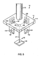
- the detector is connected to the spindle and has a mounting frame, a first detecting segment and a second detecting segment.
- the mounting frame is connected to the spindle and has a connecting rod, a bottom board and multiple mounting boards.
- the detecting segments are mounted on the mounting boards and each detecting segment has a light source and a sensor to receive light from the light source.
- the lens device is mounted securely on the turntable, extends into the detector between the mounting boards and has a supporting shaft and a spherical lens.
- the supporting shaft is mounted securely on the turntable.
- the spherical lens is mounted on an upper end of the supporting shaft to align light emitted from the light sources with the corresponding sensors via the spherical lens.
- the computer is electrically connected to the detector to receive signals outputted from the sensors of the detecting segments of the detector and has a signal processor to calculate and analyze received signals.
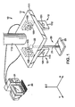
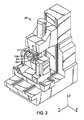
- a detecting assembly for a multi-axis machine tool 50 in accordance with the present invention comprises a detector 10, a lens device 20 and a computer 30.
- the multi-axis machine tool 50 has three linear axes (X-, Y and Z-axes), two rotation axes (A- and C-axes), a spindle 51 and a turntable 52.
- the spindle 51 is defined in the Z-axis of the multi-axis machine tool 50.
- the turntable 52 is defined below the spindle 51 and is rotates around the Z-axis of the multi-axis machine tool 50.
- the detector 10 is connected to the spindle 51 of the multi-axis machine tool 50 and has a mounting frame 11, a first detecting segment 12 and a second detecting segment 13.
- the mounting frame 11 is connected to the spindle 51 of the multi-axis machine tool 50 and has a connecting rod 113, a bottom board 111, two first mounting boards 112 and two second mounting boards 114.
- the connecting rod 113 is connected to the spindle 51 and has a connecting end and a forming end. The connecting end of the connecting rod 113 is inserted into the spindle 51.
- the bottom board 111 is formed on the forming end of the connecting rod 113 and has a bottom surface facing the turntable 52 of the multi-axis machine tool 50.
- the first mounting boards 112 are formed on and protrude from the bottom surface of the bottom board 111 and are arranged in a line parallel to the X-axis of the multi-axis machine tool 50, and the first mounting boards 112 have inner faces facing each other.
- the second mounting boards 114 are formed on and protrude from the bottom surface of the bottom board 111 and are arranged in a line parallel to the Y-axis of the multi-axis machine tool 50 and the second mounting boards 114 have inner faces facing each other.
- the first detecting segment 12 is mounted on the mounting frame 11 and has a first light source 121 and a first sensor 122.
- the first light source 121 is mounted on one of the first mounting boards 112 of the mounting frame 11.
- the first light source 121 emits a collimating beam, a focusing beam, a visible light or an invisible light.
- the first sensor 122 may be a photoelectric sensor and is mounted on the inner face of another first mounting board 112 that faces the first light source 121 to receive light from the light source and has a receiving surface 123.
- the receiving surface 123 is formed on the first sensor 122 perpendicular to the first light source 121.
- the second detecting segment 13 is mounted on the mounting frame 11 and has a second light source 131 and a second sensor 132.
- the second light source 131 is mounted on one of the second mounting boards 114 of the mounting frame 11.
- the second light source 131 emits a collimating beam, a focusing beam, a visible light or an invisible light.
- the second sensor 132 may be a photoelectric sensor and is mounted on the inner face of another second mounting board 114 that faces the second light source 131 to receive the light source and has a receiving surface 133.
- the receiving surface 133 is formed on the second sensor 132 perpendicular to the second light source 131.
- a second embodiment of the detecting assembly for a multi-axis machine tool 50 in accordance with the present invention further comprises two lenses 124, 134.
- One of the lenses 124, 134 is mounted between the first light source 121 and the first sensor 122 and the other lens 134 is mounted between the second light source 131 and the second sensor 132.
- the lens device 20 is mounted securely on the turntable 52 of the multi-axis machine tool 50, extends into the detector 10 between the mounting boards 112, 114 and has a supporting shaft 21 and a spherical lens 22.
- the supporting shaft 21 is mounted securely on the turntable 52 of the multi-axis machine tool 50 and has a lower end, an upper end and a magnet 23.
- the magnet 23 is mounted on the lower end of the supporting shaft 21 and is attracted to the turntable 52 of the multi-axis machine tool 50.
- the upper end of the supporting shaft 21 is extended into the detector 10 between the inner faces of the mounting boards 112, 114.
- the spherical lens 22 is mounted on the upper end of the supporting shaft 21 so the light sources 121, 131 of the detecting segments 12, 13 emit light to the corresponding sensors 122, 132 via the spherical lens 22.
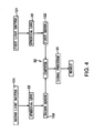
- the computer 30 is electrically connected to the detector 10 to receive signals outputted from the sensors 122, 132 of the detecting segments 12, 13 of the detector 10 and has a signal processor 31 to calculate and analyze received signals.
- the turntable 52 is moved along the X-axis and the Y-axis of the multi-axis machine tool 50 so the light sources 121, 131 emit light through the spherical lens 22 and into the receiving surfaces 123, 133 of the corresponding sensors 122, 132.
- the receiving surfaces 123, 133 will produce received signals corresponding to the emitting positions of the light sources 121, 131.
- the received signals will be sent to and calculated and analyzed by the signal processor 31 of the computer 30.
- the first light source 121 emits a light source to the first sensor 122 via the spherical lens 22 and the light source of the first light source 121 is parallel to the X-axis of the multi-axis machine tool 50.
- the first sensor 122 can detect signals of Y-axis (PSD 1y ) and Z-axis (PSD 1Z ).
- the second light source 131 emits a light source to the second sensor 132 via the spherical lens 22 and the light source of the second light source 131 is parallel to the Y-axis of the multi-axis machine tool 50.
- the second sensor 122 can detect a signal of X-axis (PSD 2x ) and Z-axis (PSD 2Z ).
- An offset of the center of the spherical lens 22 can be calculated by the equations as follows:
- a signal corresponds to the offset of the center of the spherical lens 22 will send to the multi-axis machine tool 50 to adjust the position of the turntable 52 along the X-axis and the Y-axis of the multi-axis machine tool 50. Therefore, the spherical lens 22 on the turntable 52 can be moved to let align the light sources 121, 131 and the spherical lens 22 for calibration.
- the detecting assembly in the present invention has two operating types, one of the operating types is fixing the detector 10 and moving the spherical lens 22 relative to the detector 10 to align the light sources 121, 131 through the spherical lens 22 with the corresponding the sensors 122, 132 to calculate the offset of the center of the spherical lens 22.
- the other operating type is fixing the spherical lens 22 and moving the detector 10 relative to the spherical lens 22 to align the light sources 121, 131 through the spherical lens 22 with the corresponding the sensors 122, 132 to calculate the offset of the center of the spherical lens 22.
- the errors of the multi-axis machine tool 50 can be analyzed by the signal processor 31 of the computer 30. Furthermore, the detector 10 also can be mounted on the turntable 52 and the lens device 20 can be connected to the spindle 51 of the multi-axis machine tool 50 to find the errors of the multi-axis machine tool 50.
- the detecting assembly for a multi-axis machine tool 50 uses the light sources 121, 131, the sensors 122, 132 and the spherical lens 22 to detect the offset of the center of the spherical lens 22 and to analyze the errors of the multi-axis machine tool 50 by the computer 30.
- the detector 10 needs to be connected with the spindle 51 of the multi-axis machine tool 50 and the lens device 20 mounted on the turntable 52. Then, the detecting assembly is completely assembled on the multi-axis machine tool 50 and this is convenient and timesaving.
Landscapes
- Engineering & Computer Science (AREA)
- Mechanical Engineering (AREA)
- Physics & Mathematics (AREA)
- Optics & Photonics (AREA)
- Length Measuring Devices By Optical Means (AREA)
- Machine Tool Sensing Apparatuses (AREA)
Claims (8)
- Ein Detektionsaufbau für eine Multi-Achsen Werkzeugmaschine (50), das drei lineare Achsen (X-, Y- und Z-Achsen), Multi-Rotationsachsen, eine Spindel (51) und einen Drehtisch (52) aufweist und dadurch gekennzeichnet ist, dass der Detektionsaufbau umfasst:Einen Detektor (10), der einen Montagerahmen (11) mit einer Bodenplatte (111), die eine Bodenoberfläche hat, aufweist;Zwei erste Montageplatten (112), die an der Bodenoberfläche der Bodenplatte (111) geformt sind und von dieser hervorstehen und in einer Linie parallel zu der X-Achse der Multi-Achsen Werkzeugmaschine (50) angeordnet sind, und jede der ersten Montageplatten (112) eine innere Fläche aufweist, die einander zugewandt sind; undZwei zweite Montageplatten (114), die an der Bodenoberfläche der Bodenplatte (111) geformt sind und von dieser hervorstehen und in einer Linie parallel zu der Y-Achse der Multi-Achsen Werkzeugmaschine (50) angeordnet sind, und jede der ersten Montageplatten (114) eine innere Fläche aufweist, die einander zugewandt sind;Ein erstes Detektierungssegment (12), das an dem Montagerahmen (11) montiert ist und eine erste Lichtquelle (121) aufweist, die an einer der ersten Montageplatten (112) des Montagerahmens (11) montiert ist; undEinen ersten Sensor (122), der an der Innenfläche der anderen ersten Montagesplatte (112) montiert ist, die der ersten Lichtquelle (121) zugewandt ist, um von der ersten Lichtquelle (121) emittiertes Licht zu empfangen, und der eine Empfängeroberfläche (123) aufweist, die an dem ersten Sensor (122) senkrecht zu der ersten Lichtquelle (121) geformt ist; undEin zweites Detektierungssegment (13), das an dem Montagerahmen (11) montiert ist und eine zweite Lichtquelle (131) aufweist, die an einer der zweiten Montageplatten (114) des Montagerahmens (11) montiert ist; undEinen zweiten Sensor (132), der an der Innenfläche der anderen zweiten Montagesplatte (114) montiert ist, die der ersten Lichtquelle (131) zugewandt ist, um von der zweiten Lichtquelle (131) emittiertes Licht zu empfangen, und der eine Empfängeroberfläche (133) aufweist, die an dem zweiten Sensor (132) senkrecht zu der ersten Lichtquelle (131) geformt ist;Eine Linsenvorrichtung (20), die sich in den Detektor (10) zwischen den Montageplatten (112, 114) erstreckt und eine sphärische Linse (22) aufweist, wobei die Lichtquellen (121, 131) des Detektionssegmentes (12, 13) Licht zu den korrespondierenden Sensoren (122, 132) über die sphärische Linse (22) emittieren; undEinen Computer (30), der elektrisch mit dem Detektor (10) verbundenen ist, um Signale zu empfangen, die von den Sensoren (122, 132) des Detektionssegmentes (12, 13) des Detektors (10) ausgegeben werden, und der einen Signalprozessor (31) aufweist, um die empfangenen Signale zu berechnen und zu analysieren.
- Detektionsaufbau nach Anspruch 1, wobei der Montagerahmen (11) eine an der Bodenplatte (111) geformte und von dieser hervorstehenden Verbindungsstange aufweist, um die Spindel (51) der Multi-Achsen Werkzeugmaschine (50) und die Verbindungsstange (113) zu verbinden, das ein formgebendes Ende, das an der Bodenplatte (111) gebildet ist, aufweist;
Und ein Verbindungsende, das geeignet ist, in die Spindel (51) einzusetzen und sich mit dieser zu verbinden;
Und die Linsenvorrichtung (20) einen Unterstützungsschaft (21) aufweist, der sich in den Detektor (10) zwischen den Montageplatten (112, 114) erstreckt, um die sphärische Linse (22) in dem Detektor (10) zu halten, und der ein unteres Ende aufweist, das geeignet ist, sicher an dem Drehtisch (52) der Multi-Achsen Werkzeugmaschine (50) zu montieren;
Ein sich in den Detektor (10) erstreckendes oberes Ende zwischen den inneren Flächen der Montageplatten (112, 114), um die sphärische Linse zu halten;
Und einen an dem unteren Ende des Unterstützungsschaftes (21) montierten Magneten (23), um den Drehtisch (52) der Multi-Achsen Werkzeugmaschine (50) anzuziehen. - Detektionsaufbau nach Anspruch 1 oder 2, wobei der Detektionsaufbau zwei Linsen (124, 134) aufweist, wobei eine der Linsen (124, 134) zwischen der ersten Lichtquelle (121) und dem ersten Lichtsensor (122) montiert ist und die andere Linse (134) zwischen der zweiten Lichtquelle (131) und dem zweiten Sensor (132) montiert ist.
- Detektionsaufbau nach Anspruch 3, wobei jeder Sensor (122, 132) ein photoelektrischer Sensor ist.
- Detektionsaufbau nach Anspruch 4, wobei jede Lichtquelle (121, 131) einen fokussierten Strahl emittiert.
- Detektionsaufbau nach Anspruch 4, wobei jede Lichtquelle (121, 131) einen kollimierten Strahl emittiert.
- Detektionsaufbau nach Anspruch 4 oder 5 oder 6, wobei jede Lichtquelle (121, 131) eine sichtbare Lichtquelle ist.
- Detektionsaufbau nach Anspruch 4 oder 5 oder 6, wobei jede Lichtquelle (121, 131) eine unsichtbare Lichtquelle ist.
Applications Claiming Priority (1)
| Application Number | Priority Date | Filing Date | Title |
|---|---|---|---|
| TW98145473A TW201121700A (en) | 2009-12-29 | 2009-12-29 | Measurement device for multi-axis machine tool. |
Publications (2)
| Publication Number | Publication Date |
|---|---|
| EP2340914A1 EP2340914A1 (de) | 2011-07-06 |
| EP2340914B1 true EP2340914B1 (de) | 2012-12-26 |
Family
ID=43778511
Family Applications (1)
| Application Number | Title | Priority Date | Filing Date |
|---|---|---|---|
| EP20100016091 Active EP2340914B1 (de) | 2009-12-29 | 2010-12-27 | Detektionsanordnung für ein Mehrachsen-Maschinenwerkzeug |
Country Status (3)
| Country | Link |
|---|---|
| EP (1) | EP2340914B1 (de) |
| JP (1) | JP5038481B2 (de) |
| TW (1) | TW201121700A (de) |
Families Citing this family (4)
| Publication number | Priority date | Publication date | Assignee | Title |
|---|---|---|---|---|
| TWI496651B (zh) * | 2013-01-15 | 2015-08-21 | Nat Univ Chung Hsing | 檢測裝置與使用其之檢測方法 |
| TWI632344B (zh) * | 2017-04-17 | 2018-08-11 | 國立虎尾科技大學 | 光學式轉軸多自由度誤差檢測裝置與方法(二) |
| TWI749961B (zh) | 2020-12-22 | 2021-12-11 | 雷應科技股份有限公司 | 刀具檢測器 |
| TWI785914B (zh) * | 2021-12-02 | 2022-12-01 | 財團法人工業技術研究院 | 雙旋轉軸的幾何誤差的獲取方法與獲取設備 |
Family Cites Families (4)
| Publication number | Priority date | Publication date | Assignee | Title |
|---|---|---|---|---|
| US6269284B1 (en) * | 1997-05-09 | 2001-07-31 | Kam C. Lau | Real time machine tool error correction using global differential wet modeling |
| US6775013B2 (en) * | 2001-03-07 | 2004-08-10 | Optodyne, Inc. | Method and apparatus for measuring displacement or motion error |
| DE102005008055B4 (de) * | 2005-02-22 | 2009-01-02 | Deckel Maho Pfronten Gmbh | Verfahren zum Vermessen einer programmgesteuerten Werkzeugmaschine |
| FR2928289B1 (fr) * | 2008-03-05 | 2010-05-07 | Peugeot Citroen Automobiles Sa | Procede de controle de la geometrie d'une machine a commande numerique pour l'usinage 5 axes. |
-
2009
- 2009-12-29 TW TW98145473A patent/TW201121700A/zh unknown
-
2010
- 2010-12-17 JP JP2010281741A patent/JP5038481B2/ja active Active
- 2010-12-27 EP EP20100016091 patent/EP2340914B1/de active Active
Also Published As
| Publication number | Publication date |
|---|---|
| TW201121700A (en) | 2011-07-01 |
| JP5038481B2 (ja) | 2012-10-03 |
| EP2340914A1 (de) | 2011-07-06 |
| TWI378843B (de) | 2012-12-11 |
| JP2011137812A (ja) | 2011-07-14 |
Similar Documents
| Publication | Publication Date | Title |
|---|---|---|
| US7852478B1 (en) | Detecting assembly for a multi-axis machine tool | |
| US9862097B2 (en) | Industrial robot system having sensor assembly | |
| US8116902B2 (en) | Method of detecting a dynamic path of a five-axis machine tool and dectecting assembly for the same | |
| US5798828A (en) | Laser aligned five-axis position measurement device | |
| US8659763B2 (en) | Method for machine measurement | |
| KR101159644B1 (ko) | 레이저 간섭계를 이용한 공작기계 인덱스 테이블의 기하학적 오차 측정장치 및 그 방법 | |
| EP3392609A1 (de) | Optische detektionsvorrichtung zur detektion eines fehlers des freiheitsgrades einer spindel und detektionsverfahren dafür | |
| US20110246115A1 (en) | Method for calculating probe mounting position in on-machine measuring device | |
| EP2340914B1 (de) | Detektionsanordnung für ein Mehrachsen-Maschinenwerkzeug | |
| CN114248154A (zh) | 五轴机床空间定位精度检测装置及方法 | |
| US10359266B2 (en) | Position measurement method of object in machine tool and position measurement system of the same | |
| CN115922439B (zh) | 数控五轴机床加工精度检测方法 | |
| JP4571256B2 (ja) | 逐次2点法による形状精度測定装置および逐次2点法による形状精度測定用レーザ変位計間隔測定方法 | |
| US8401691B2 (en) | Dynamic metrology methods and systems | |
| CN118417608A (zh) | 用于轮圈加工的机床以及保持装置 | |
| JP2008073813A (ja) | マシニングセンタによる加工方法 | |
| EP1457289A1 (de) | Vorrichtung zum Kontrollieren der Position einer Spindel in einer Werkzeugmaschine | |
| CN106392773A (zh) | 一种五轴联动机床主轴头姿态角测量装置及测量方法 | |
| CN2925775Y (zh) | 钻头立体测量划线仪 | |
| CN112325777B (zh) | 一种测量转轴六自由度几何误差的光学测量装置 | |
| TWI283616B (en) | A drilling and tapping measurement device by using laser and position sensors | |
| JP6969523B2 (ja) | 切削装置 | |
| KR20140081396A (ko) | 다축 공작 기계를 위한 무선 검출-보상 어셈블리 | |
| EP1566240A1 (de) | Ausrichtgerät | |
| JP2007271601A (ja) | 光学式測定器及び光学式測定方法 |
Legal Events
| Date | Code | Title | Description |
|---|---|---|---|
| PUAI | Public reference made under article 153(3) epc to a published international application that has entered the european phase |
Free format text: ORIGINAL CODE: 0009012 |
|
| AK | Designated contracting states |
Kind code of ref document: A1 Designated state(s): AL AT BE BG CH CY CZ DE DK EE ES FI FR GB GR HR HU IE IS IT LI LT LU LV MC MK MT NL NO PL PT RO RS SE SI SK SM TR |
|
| AX | Request for extension of the european patent |
Extension state: BA ME |
|
| 17P | Request for examination filed |
Effective date: 20110617 |
|
| GRAP | Despatch of communication of intention to grant a patent |
Free format text: ORIGINAL CODE: EPIDOSNIGR1 |
|
| GRAS | Grant fee paid |
Free format text: ORIGINAL CODE: EPIDOSNIGR3 |
|
| GRAA | (expected) grant |
Free format text: ORIGINAL CODE: 0009210 |
|
| AK | Designated contracting states |
Kind code of ref document: B1 Designated state(s): AL AT BE BG CH CY CZ DE DK EE ES FI FR GB GR HR HU IE IS IT LI LT LU LV MC MK MT NL NO PL PT RO RS SE SI SK SM TR |
|
| REG | Reference to a national code |
Ref country code: GB Ref legal event code: FG4D |
|
| REG | Reference to a national code |
Ref country code: CH Ref legal event code: EP |
|
| REG | Reference to a national code |
Ref country code: AT Ref legal event code: REF Ref document number: 590190 Country of ref document: AT Kind code of ref document: T Effective date: 20130115 |
|
| REG | Reference to a national code |
Ref country code: CH Ref legal event code: NV Representative=s name: FIAMMENGHI-FIAMMENGHI, CH |
|
| REG | Reference to a national code |
Ref country code: CH Ref legal event code: NV Representative=s name: FIAMMENGHI-FIAMMENGHI, CH |
|
| REG | Reference to a national code |
Ref country code: DE Ref legal event code: R096 Ref document number: 602010004248 Country of ref document: DE Effective date: 20130307 |
|
| PG25 | Lapsed in a contracting state [announced via postgrant information from national office to epo] |
Ref country code: LT Free format text: LAPSE BECAUSE OF FAILURE TO SUBMIT A TRANSLATION OF THE DESCRIPTION OR TO PAY THE FEE WITHIN THE PRESCRIBED TIME-LIMIT Effective date: 20121226 Ref country code: HR Free format text: LAPSE BECAUSE OF FAILURE TO SUBMIT A TRANSLATION OF THE DESCRIPTION OR TO PAY THE FEE WITHIN THE PRESCRIBED TIME-LIMIT Effective date: 20121226 Ref country code: FI Free format text: LAPSE BECAUSE OF FAILURE TO SUBMIT A TRANSLATION OF THE DESCRIPTION OR TO PAY THE FEE WITHIN THE PRESCRIBED TIME-LIMIT Effective date: 20121226 Ref country code: NO Free format text: LAPSE BECAUSE OF FAILURE TO SUBMIT A TRANSLATION OF THE DESCRIPTION OR TO PAY THE FEE WITHIN THE PRESCRIBED TIME-LIMIT Effective date: 20130326 Ref country code: SE Free format text: LAPSE BECAUSE OF FAILURE TO SUBMIT A TRANSLATION OF THE DESCRIPTION OR TO PAY THE FEE WITHIN THE PRESCRIBED TIME-LIMIT Effective date: 20121226 |
|
| REG | Reference to a national code |
Ref country code: AT Ref legal event code: MK05 Ref document number: 590190 Country of ref document: AT Kind code of ref document: T Effective date: 20121226 |
|
| REG | Reference to a national code |
Ref country code: LT Ref legal event code: MG4D |
|
| REG | Reference to a national code |
Ref country code: NL Ref legal event code: VDEP Effective date: 20121226 |
|
| PG25 | Lapsed in a contracting state [announced via postgrant information from national office to epo] |
Ref country code: LV Free format text: LAPSE BECAUSE OF FAILURE TO SUBMIT A TRANSLATION OF THE DESCRIPTION OR TO PAY THE FEE WITHIN THE PRESCRIBED TIME-LIMIT Effective date: 20121226 Ref country code: GR Free format text: LAPSE BECAUSE OF FAILURE TO SUBMIT A TRANSLATION OF THE DESCRIPTION OR TO PAY THE FEE WITHIN THE PRESCRIBED TIME-LIMIT Effective date: 20130327 Ref country code: SI Free format text: LAPSE BECAUSE OF FAILURE TO SUBMIT A TRANSLATION OF THE DESCRIPTION OR TO PAY THE FEE WITHIN THE PRESCRIBED TIME-LIMIT Effective date: 20121226 |
|
| PG25 | Lapsed in a contracting state [announced via postgrant information from national office to epo] |
Ref country code: CZ Free format text: LAPSE BECAUSE OF FAILURE TO SUBMIT A TRANSLATION OF THE DESCRIPTION OR TO PAY THE FEE WITHIN THE PRESCRIBED TIME-LIMIT Effective date: 20121226 Ref country code: BE Free format text: LAPSE BECAUSE OF FAILURE TO SUBMIT A TRANSLATION OF THE DESCRIPTION OR TO PAY THE FEE WITHIN THE PRESCRIBED TIME-LIMIT Effective date: 20121226 Ref country code: IS Free format text: LAPSE BECAUSE OF FAILURE TO SUBMIT A TRANSLATION OF THE DESCRIPTION OR TO PAY THE FEE WITHIN THE PRESCRIBED TIME-LIMIT Effective date: 20130426 Ref country code: MC Free format text: LAPSE BECAUSE OF NON-PAYMENT OF DUE FEES Effective date: 20121231 Ref country code: AT Free format text: LAPSE BECAUSE OF FAILURE TO SUBMIT A TRANSLATION OF THE DESCRIPTION OR TO PAY THE FEE WITHIN THE PRESCRIBED TIME-LIMIT Effective date: 20121226 Ref country code: BG Free format text: LAPSE BECAUSE OF FAILURE TO SUBMIT A TRANSLATION OF THE DESCRIPTION OR TO PAY THE FEE WITHIN THE PRESCRIBED TIME-LIMIT Effective date: 20130326 Ref country code: EE Free format text: LAPSE BECAUSE OF FAILURE TO SUBMIT A TRANSLATION OF THE DESCRIPTION OR TO PAY THE FEE WITHIN THE PRESCRIBED TIME-LIMIT Effective date: 20121226 Ref country code: ES Free format text: LAPSE BECAUSE OF FAILURE TO SUBMIT A TRANSLATION OF THE DESCRIPTION OR TO PAY THE FEE WITHIN THE PRESCRIBED TIME-LIMIT Effective date: 20130406 Ref country code: RS Free format text: LAPSE BECAUSE OF FAILURE TO SUBMIT A TRANSLATION OF THE DESCRIPTION OR TO PAY THE FEE WITHIN THE PRESCRIBED TIME-LIMIT Effective date: 20121226 Ref country code: SK Free format text: LAPSE BECAUSE OF FAILURE TO SUBMIT A TRANSLATION OF THE DESCRIPTION OR TO PAY THE FEE WITHIN THE PRESCRIBED TIME-LIMIT Effective date: 20121226 |
|
| PG25 | Lapsed in a contracting state [announced via postgrant information from national office to epo] |
Ref country code: RO Free format text: LAPSE BECAUSE OF FAILURE TO SUBMIT A TRANSLATION OF THE DESCRIPTION OR TO PAY THE FEE WITHIN THE PRESCRIBED TIME-LIMIT Effective date: 20121226 Ref country code: NL Free format text: LAPSE BECAUSE OF FAILURE TO SUBMIT A TRANSLATION OF THE DESCRIPTION OR TO PAY THE FEE WITHIN THE PRESCRIBED TIME-LIMIT Effective date: 20121226 Ref country code: PL Free format text: LAPSE BECAUSE OF FAILURE TO SUBMIT A TRANSLATION OF THE DESCRIPTION OR TO PAY THE FEE WITHIN THE PRESCRIBED TIME-LIMIT Effective date: 20121226 Ref country code: PT Free format text: LAPSE BECAUSE OF FAILURE TO SUBMIT A TRANSLATION OF THE DESCRIPTION OR TO PAY THE FEE WITHIN THE PRESCRIBED TIME-LIMIT Effective date: 20130426 |
|
| REG | Reference to a national code |
Ref country code: IE Ref legal event code: MM4A |
|
| PG25 | Lapsed in a contracting state [announced via postgrant information from national office to epo] |
Ref country code: IE Free format text: LAPSE BECAUSE OF NON-PAYMENT OF DUE FEES Effective date: 20121227 Ref country code: DK Free format text: LAPSE BECAUSE OF FAILURE TO SUBMIT A TRANSLATION OF THE DESCRIPTION OR TO PAY THE FEE WITHIN THE PRESCRIBED TIME-LIMIT Effective date: 20121226 |
|
| PLBE | No opposition filed within time limit |
Free format text: ORIGINAL CODE: 0009261 |
|
| STAA | Information on the status of an ep patent application or granted ep patent |
Free format text: STATUS: NO OPPOSITION FILED WITHIN TIME LIMIT |
|
| PG25 | Lapsed in a contracting state [announced via postgrant information from national office to epo] |
Ref country code: MT Free format text: LAPSE BECAUSE OF FAILURE TO SUBMIT A TRANSLATION OF THE DESCRIPTION OR TO PAY THE FEE WITHIN THE PRESCRIBED TIME-LIMIT Effective date: 20121226 Ref country code: CY Free format text: LAPSE BECAUSE OF FAILURE TO SUBMIT A TRANSLATION OF THE DESCRIPTION OR TO PAY THE FEE WITHIN THE PRESCRIBED TIME-LIMIT Effective date: 20121226 Ref country code: AL Free format text: LAPSE BECAUSE OF FAILURE TO SUBMIT A TRANSLATION OF THE DESCRIPTION OR TO PAY THE FEE WITHIN THE PRESCRIBED TIME-LIMIT Effective date: 20121226 |
|
| 26N | No opposition filed |
Effective date: 20130927 |
|
| REG | Reference to a national code |
Ref country code: FR Ref legal event code: ST Effective date: 20131107 |
|
| PG25 | Lapsed in a contracting state [announced via postgrant information from national office to epo] |
Ref country code: IT Free format text: LAPSE BECAUSE OF FAILURE TO SUBMIT A TRANSLATION OF THE DESCRIPTION OR TO PAY THE FEE WITHIN THE PRESCRIBED TIME-LIMIT Effective date: 20121226 |
|
| REG | Reference to a national code |
Ref country code: DE Ref legal event code: R097 Ref document number: 602010004248 Country of ref document: DE Effective date: 20130927 |
|
| PG25 | Lapsed in a contracting state [announced via postgrant information from national office to epo] |
Ref country code: FR Free format text: LAPSE BECAUSE OF NON-PAYMENT OF DUE FEES Effective date: 20130226 |
|
| PG25 | Lapsed in a contracting state [announced via postgrant information from national office to epo] |
Ref country code: TR Free format text: LAPSE BECAUSE OF FAILURE TO SUBMIT A TRANSLATION OF THE DESCRIPTION OR TO PAY THE FEE WITHIN THE PRESCRIBED TIME-LIMIT Effective date: 20121226 |
|
| PG25 | Lapsed in a contracting state [announced via postgrant information from national office to epo] |
Ref country code: SM Free format text: LAPSE BECAUSE OF FAILURE TO SUBMIT A TRANSLATION OF THE DESCRIPTION OR TO PAY THE FEE WITHIN THE PRESCRIBED TIME-LIMIT Effective date: 20121226 Ref country code: LU Free format text: LAPSE BECAUSE OF NON-PAYMENT OF DUE FEES Effective date: 20121227 |
|
| PG25 | Lapsed in a contracting state [announced via postgrant information from national office to epo] |
Ref country code: HU Free format text: LAPSE BECAUSE OF FAILURE TO SUBMIT A TRANSLATION OF THE DESCRIPTION OR TO PAY THE FEE WITHIN THE PRESCRIBED TIME-LIMIT Effective date: 20101227 |
|
| PG25 | Lapsed in a contracting state [announced via postgrant information from national office to epo] |
Ref country code: MK Free format text: LAPSE BECAUSE OF FAILURE TO SUBMIT A TRANSLATION OF THE DESCRIPTION OR TO PAY THE FEE WITHIN THE PRESCRIBED TIME-LIMIT Effective date: 20121226 |
|
| REG | Reference to a national code |
Ref country code: CH Ref legal event code: PL |
|
| REG | Reference to a national code |
Ref country code: CH Ref legal event code: AECN Free format text: LE BREVET A ETE REACTIVE SELON LA DEMANDE DE POURSUITE DE LA PROCEDURE DU 27.08.2020. Ref country code: CH Ref legal event code: NV Representative=s name: REUTELER AND CIE S.A., CH |
|
| PGFP | Annual fee paid to national office [announced via postgrant information from national office to epo] |
Ref country code: DE Payment date: 20241217 Year of fee payment: 15 |
|
| PGFP | Annual fee paid to national office [announced via postgrant information from national office to epo] |
Ref country code: GB Payment date: 20241230 Year of fee payment: 15 |
|
| PGFP | Annual fee paid to national office [announced via postgrant information from national office to epo] |
Ref country code: CH Payment date: 20250401 Year of fee payment: 15 |