EP2340901B9 - Method for making a cast component - Google Patents
Method for making a cast component Download PDFInfo
- Publication number
- EP2340901B9 EP2340901B9 EP10194254.8A EP10194254A EP2340901B9 EP 2340901 B9 EP2340901 B9 EP 2340901B9 EP 10194254 A EP10194254 A EP 10194254A EP 2340901 B9 EP2340901 B9 EP 2340901B9
- Authority
- EP
- European Patent Office
- Prior art keywords
- feeder
- casting
- core
- engine block
- mold
- Prior art date
- Legal status (The legal status is an assumption and is not a legal conclusion. Google has not performed a legal analysis and makes no representation as to the accuracy of the status listed.)
- Active
Links
- 238000000034 method Methods 0.000 title claims description 26
- 238000005266 casting Methods 0.000 claims description 83
- 229910001338 liquidmetal Inorganic materials 0.000 claims description 13
- 238000001816 cooling Methods 0.000 claims description 9
- 238000004519 manufacturing process Methods 0.000 claims description 8
- 235000011837 pasties Nutrition 0.000 claims 1
- 239000000463 material Substances 0.000 description 10
- 238000007711 solidification Methods 0.000 description 8
- 230000008023 solidification Effects 0.000 description 8
- XLYOFNOQVPJJNP-UHFFFAOYSA-N water Substances O XLYOFNOQVPJJNP-UHFFFAOYSA-N 0.000 description 5
- 239000007788 liquid Substances 0.000 description 4
- 208000015943 Coeliac disease Diseases 0.000 description 3
- 238000005192 partition Methods 0.000 description 2
- 239000004576 sand Substances 0.000 description 2
- 229910001060 Gray iron Inorganic materials 0.000 description 1
- 229910000831 Steel Inorganic materials 0.000 description 1
- 238000009825 accumulation Methods 0.000 description 1
- 239000003570 air Substances 0.000 description 1
- 239000012080 ambient air Substances 0.000 description 1
- 230000015572 biosynthetic process Effects 0.000 description 1
- 238000002485 combustion reaction Methods 0.000 description 1
- 238000010276 construction Methods 0.000 description 1
- 239000000112 cooling gas Substances 0.000 description 1
- 239000000110 cooling liquid Substances 0.000 description 1
- 238000005336 cracking Methods 0.000 description 1
- 230000001419 dependent effect Effects 0.000 description 1
- 238000011161 development Methods 0.000 description 1
- 230000018109 developmental process Effects 0.000 description 1
- 230000000694 effects Effects 0.000 description 1
- 230000002349 favourable effect Effects 0.000 description 1
- 239000012530 fluid Substances 0.000 description 1
- 230000005484 gravity Effects 0.000 description 1
- 238000005338 heat storage Methods 0.000 description 1
- 239000011344 liquid material Substances 0.000 description 1
- 238000003754 machining Methods 0.000 description 1
- 239000002184 metal Substances 0.000 description 1
- 229910052751 metal Inorganic materials 0.000 description 1
- 238000007493 shaping process Methods 0.000 description 1
- 239000010959 steel Substances 0.000 description 1
- 238000003860 storage Methods 0.000 description 1
Images

Classifications
-
- B—PERFORMING OPERATIONS; TRANSPORTING
- B22—CASTING; POWDER METALLURGY
- B22C—FOUNDRY MOULDING
- B22C9/00—Moulds or cores; Moulding processes
- B22C9/08—Features with respect to supply of molten metal, e.g. ingates, circular gates, skim gates
-
- B—PERFORMING OPERATIONS; TRANSPORTING
- B22—CASTING; POWDER METALLURGY
- B22C—FOUNDRY MOULDING
- B22C9/00—Moulds or cores; Moulding processes
- B22C9/10—Cores; Manufacture or installation of cores
- B22C9/108—Installation of cores
-
- B—PERFORMING OPERATIONS; TRANSPORTING
- B22—CASTING; POWDER METALLURGY
- B22D—CASTING OF METALS; CASTING OF OTHER SUBSTANCES BY THE SAME PROCESSES OR DEVICES
- B22D15/00—Casting using a mould or core of which a part significant to the process is of high thermal conductivity, e.g. chill casting; Moulds or accessories specially adapted therefor
- B22D15/02—Casting using a mould or core of which a part significant to the process is of high thermal conductivity, e.g. chill casting; Moulds or accessories specially adapted therefor of cylinders, pistons, bearing shells or like thin-walled objects
-
- B—PERFORMING OPERATIONS; TRANSPORTING
- B22—CASTING; POWDER METALLURGY
- B22D—CASTING OF METALS; CASTING OF OTHER SUBSTANCES BY THE SAME PROCESSES OR DEVICES
- B22D25/00—Special casting characterised by the nature of the product
Definitions
- the invention relates to a method for producing a casting, in particular an engine block, comprising the steps of: producing a feeder core, inserting the feeder core into a casting mold and filling the casting mold with a liquid metal.
- crankcases and engine blocks are manufactured in various casting processes known in the art.
- Highly stressed crankcases or engine blocks used in engines such as diesel engines or turbocharged supercharged engines are manufactured in low pressure, core packaged, or gravity casting. In these methods, the solidification of the liquid material from the cylinder head side to the crank chamber side or from the crank chamber side of the engine block to the cylinder head side.
- the US 1,670,725 shows a method and apparatus for casting wheel hubs.
- the JP 57 103 755 shows a method for producing cast components with a feeder core, in which the outlet opening of the feeder is optimized from the feeder core by suitable geometrical measures.
- crankcase side bearing block or the combustion chamber web on the cylinder head solidifies faster than the respective other, opposite end of the engine block by the described solidification course.
- the solidification time is significantly involved in achieving favorable material properties of the engine block.
- engine blocks or crankcases produced by the method according to the prior art are either cylinder headboards or high-strength storage chairs.
- Another disadvantage of the known methods is that the solidification of the tool from one end region to another end region leads to high solidification times and thus to long process times. Furthermore, high mold temperatures are required, resulting in a particularly high wear of the tool.
- the present invention has for its object to provide a method with improved properties, which overcomes the above-mentioned disadvantages of the prior art.
- a method for producing a casting comprises the steps of: producing a feeder core, inserting the feeder core into a casting mold and filling the casting mold with a liquid metal. Furthermore, the method may include the step of positioning the feeder core inside the mold. Such a positioning of the feeder core causes the feeding to take place from a central area during the production of the casting.
- the method may include the step of: creating a recess in the casting by positioning the feeder core at a predetermined position inside the casting mold. Due to the positioning of the feeder core in the interior of the casting mold and thus also in the interior of the cast part to be produced, the feeder core cools down last and thus maintains as long as possible a high component temperature. This allows the feeder to be kept in a liquid to semi-liquid or doughy state for a long time, thereby ensuring that the casting is fed with liquid metal during solidification.
- a predetermined position we enter Area preferred, which is arranged centrally in the longitudinal, transverse and vertical direction of the casting and thus corresponds to a central area.
- the method may be characterized in that, after complete filling of the casting mold with liquid metal, the casting is cooled substantially simultaneously, opposite outer regions to the inner region.
- edge regions of the casting which extend from the surface to the component center.
- the outer regions preferably correspond to an area where a cylinder head is connected, an area where a crankcase is connected to the engine block, or an area where the crankshaft is supported to the engine block.
- the method may be characterized in that the casting is removable from the mold when a feeder is inside the feeder core after cooling at least in a partially dough-like state.
- the method may be characterized in that the feeder is arranged in the interior of at least one cylinder of an engine block to be produced, wherein the feeder is connected to a predetermined area on an inner wall of the cylinder.
- the invention relates to a casting, in particular a motor block with at least one recess, which in the interior of the Casting is arranged and at least one feeder. Furthermore, the feeder can be provided in the interior of the recess.
- the recess may have an inner wall, wherein the inner wall is connected in at least one predetermined area with the feeder.
- FIGS. 1 to 3 show a casting 10 according to the invention, which is shown by way of example in the form of a cylinder block.
- FIG. 1 shows a plan view of a first outer region 12 of the casting 10.
- This first outer region 12 corresponds to an upper end portion of the cylinder block 10, on which a cylinder head of the engine can be mounted.
- the upper outer region 12 thus corresponds to the cylinder head web.
- two recesses 15 are shown by way of example and not by way of limitation. These recesses 15 are cylinders 15 in which the pistons of the engine are later installed. In the casting 10, these recesses 15 may be provided as through openings with a circular, oval or polygonal cross-section. Alternatively, in the casting 10 immediately after removal from a mold, the recesses 15 may be formed as blind holes with round, oval or polygonal cross-sectional shapes. In both the through-hole embodiment and the blind-hole embodiment, the recesses 15 may have a tapered, prismatic, or cylindrical shape from the cylinder head end to a crankshaft end of the engine block.
- each feeder 13 are shown, which are arranged substantially coaxially in the recesses 15.
- the feeders 13 are connected to the cylinder block 10 via feed connections 13a.
- the recesses 15 have an inner wall 15a, which tapers from the cylinder head side to the crankshaft side of the engine block 10 and in this direction has a tapered, circular cross-section.
- the feeder connections 13a are connected to the inner wall 15a of the recess 15 in a predetermined area 15b.
- the predetermined area 15b is located in the region of the casting longitudinal axis, which corresponds to the section line AA at the level of two tie rods 17, which are adjacent in the transverse direction of the engine block, as shown FIG. 1 is recognizable.
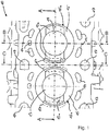
- FIG. 2 is a vertical direction of the casting 10 defined by the arrow Z.
- the above-mentioned predetermined areas of the memory connection 13b are in casting upright Z below water jackets 14, as shown FIG. 2 seen.
- the feeder connections 13a extend in the engine block longitudinal direction, namely below the deepest region of the water jackets 26.
- the water jackets form recesses in the engine block, which are used as cooling channels.
- these predetermined areas may also extend in the transverse direction of the cylinder block, i. in a direction corresponding to the section lines B-B and C-C.
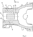
- the feeder connections 13a extend substantially perpendicular to the longitudinal direction of the engine block 10, between two longitudinally adjacent tie rods 17, and are connected below the water jacket cores 26 to an inner wall 15a of the recess 15. A diagonal orientation of the feeder connections 13a is also conceivable.
- the tie-rod regions 17 are regions of material accumulation used during the casting process for distributing liquid metal to achieve better filling of the casting mold 20. In these areas, which can thus be used as channels later holes are provided with threads to which the cylinder head of a motor is screwed.
- the casting mold 20 comprises at least two side parts 21 a and 21 b, a lower part or a base part 22 and a top part 23. These parts are shaping the outer casting contour and are preferably made of steel.
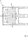
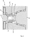
- a feeder core 24 is provided inside the casting mold 20, as shown FIG. 4 seen.
- the FIG. 4 represents a sectional view through a mold along the line BB of the casting 10 from FIG. 1 In other words, one would make the mold 20 for the production of the casting 10 from FIG. 1 Cut along the section BB, so you would make the presentation FIG. 4 receive.
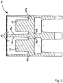
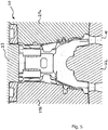
- the same applies to the presentation FIG. 5 with the difference that the FIG.
- FIG. 5 a sectional view along the interface CC FIG. 1 equivalent.
- the tool part is cut in a region between two cylinders adjacent to one another in the longitudinal direction of the engine block.
- the casting mold 20 has feeds 16 in the lower region. These inlets represent sprues 16, via which the liquid metal is introduced into the mold 20 during the casting process.
- FIG. 6 shows a sectional view along the section line AA FIG. 1 through the casting mold 20.
- the feeder cores 24 are arranged centrally in an inner region of the engine block, ie in the transverse direction, and are clamped between the upper part 23 and the lower part 22.
- the feeder cores 24 have passages 25 through which the liquid metal can flow into a cavity 27.
- the feeders 13 are formed during the casting process and the feed connections 13a are formed in the passages 25.
- the feeder core 24 is produced. This has a quill shape, with an inner cavity 27 and is preferably formed of sand.
- the mold 20 is assembled, wherein the side parts 21 a, 21 b, the lower part 22 and the upper part 23 are aligned and fixed in a predetermined arrangement to each other.
- the feeder cores 24 are attached at predetermined positions in the mold 20.
- Water jacket cores 26 are produced in parallel and likewise introduced into the casting mold 20.
- the water jacket cores 26 are, as well as the feeder cores, formed of sand and serve to hold in the later casting 10 openings that are used as cooling channels. These cooling channels are then flushed in the running engine with a fluid, preferably a cooling liquid or a cooling gas to keep the running engine at operating temperature.
- the casting mold 20 is filled with liquid metal in the subsequent step.
- the liquid metal enters the interior via the sprues 16, i. in the inner cavities of the mold 20 and is distributed in the mold 20, where it flows through the passages 25 into the cavity 27 of the feeder cores 24 and forms the feeder 13.
- the cooling takes place.
- the casting mold 20 is cooled substantially simultaneously from the upper outer region 12 and from the lower outer region 11.
- the cylinder head land area 12 and the bearing seat area 11 cool rapidly and thus obtain particularly high strength characteristics. Consequently, in the casting 10, a solidification direction or a course of solidification results, which runs from the cylinder head region 12 and the bearing block region 11, or the region at which the crankcase is screwed, to the center of the casting 10.
- the feeder 13 acts as a thermal heat storage and solidifies as the last portion of the casting.
- the casting 10 can also be removed more quickly from the casting mold 20. Since the surface or the outer edge regions are already cooled when the casting 10 is removed, the risk of cracking during removal from the mold 20 is reduced. The complete cooling of the casting 10, or the residual cooling of the feeder 13, can then take place in the ambient air.
- the method according to the invention provides a significantly shorter demolding time and thus a much shorter cycle time compared to the methods known from the prior art.
- the positioning of the feeders in a central region of the mold further results in the advantage that smaller feeders can be used so that the circulation material is reduced.
- the loop material is the material that must be removed from the casting immediately after the casting process, such as sprues, feeders, or machining allowances. These are usually melted down and reused. The smaller the feeders, the lower the circulation material in the process chain, which reduces the energy requirement of the process.
- the feeder core 24 and the water jacket cores 26 are removed and the feeder 13 and the feeder connections 13a are cut away. Even though reference has been made above to a feeder 13 and a feeder core 24, the same applies to embodiments in which a plurality of feeder cores are used.
- AlSi7, AlSi8, gray cast iron or any other metal is particularly suitable as material for the engine block or crankcase produced according to the invention.
- the casting process preferably takes place in the down process, wherein for the filling of the mold 20, in particular the furnace filling level, the component height of the casting mold and the relative arrangement of component and furnace are essential factors.
Description
Die Erfindung betrifft ein Verfahren zur Herstellung eines Gussteils, insbesondere eines Motorblocks, mit den Schritten Erzeugen: eines Speiserkerns, Einsetzen des Speiserkerns in eine Gussform und Befüllen der Gussform mit einem Flüssigmetall.The invention relates to a method for producing a casting, in particular an engine block, comprising the steps of: producing a feeder core, inserting the feeder core into a casting mold and filling the casting mold with a liquid metal.
Derzeit werden Kurbelgehäuse und Motorblöcke in verschiedenen Gießverfahren hergestellt, die aus dem Stand der Technik bekannt sind. Hochbeanspruchte Kurbelgehäuse bzw. Motorblöcke, die in Motoren, wie beispielsweise Dieselmotoren oder mittels Turboladern aufgeladenen Motoren Verwendung finden, werden im Niederdruckguss-, im Corepackage- oder im Schwerkraftgussverfahren hergestellt. Bei diesen Verfahren läuft die Erstarrung des flüssigen Materials von der Zylinderkopfseite zur Kurbelraumseite oder von der Kurbelraumseite des Motorblocks zur Zylinderkopfseite.Currently, crankcases and engine blocks are manufactured in various casting processes known in the art. Highly stressed crankcases or engine blocks used in engines such as diesel engines or turbocharged supercharged engines are manufactured in low pressure, core packaged, or gravity casting. In these methods, the solidification of the liquid material from the cylinder head side to the crank chamber side or from the crank chamber side of the engine block to the cylinder head side.
Die
Aus der
Aus der
Die
Solche Verfahren weisen jedoch den Nachteil auf, dass durch den beschriebenen Erstarrungsverlauf entweder der kurbelraumseitige Lagerstuhl oder der Brennraumsteg am Zylinderkopf schneller erstarrt als das jeweilige andere, gegenüberliegende Ende des Motorblocks. Die Erstarrungszeit ist maßgeblich beteiligt an der Erzielung günstiger Materialeigenschaften des Motorblocks. Dabei sind besonders gute Materialeigenschaften zur erzielen, je schneller das Werkstück erstarrt. Folglich weisen Motorblöcke bzw. Kurbelgehäuse, die mit dem Verfahren nach dem Stand der Technik hergestellt sind, entweder Zylinderkopfstege oder Lagerstühle mit hohen Festigkeitswerten auf. Ein weiterer Nachteil der bekannten Verfahren liegt darin, dass die Erstarrung des Werkzeuges von einem Endbereich zu einem anderen Endbereich hin zu hohen Erstarrungszeiten und damit zu langen Prozesszeiten führt. Ferner werden auch hohe Werkzeugtemperaturen benötigt, wodurch sich ein besonders hoher Verschleiß des Werkzeuges ergibt.However, such methods have the disadvantage that either the crankcase side bearing block or the combustion chamber web on the cylinder head solidifies faster than the respective other, opposite end of the engine block by the described solidification course. The solidification time is significantly involved in achieving favorable material properties of the engine block. Here are particularly good material properties to achieve, the faster the workpiece solidifies. Consequently, engine blocks or crankcases produced by the method according to the prior art are either cylinder headboards or high-strength storage chairs. Another disadvantage of the known methods is that the solidification of the tool from one end region to another end region leads to high solidification times and thus to long process times. Furthermore, high mold temperatures are required, resulting in a particularly high wear of the tool.
Die vorliegende Erfindung macht es sich zur Aufgabe, ein Verfahren anzugeben, mit verbesserten Eigenschaften, welche die oben genannten Nachteile des Standes der Technik überwindet.The present invention has for its object to provide a method with improved properties, which overcomes the above-mentioned disadvantages of the prior art.
Die Lösung der Aufgabe erfolgt mit den Merkmalen der unabhängigen Ansprüche. Bevorzugte Ausführungsformen und Weiterbildungen der Erfindung sind Gegenstand der Unteransprüche.The object is achieved by the features of the independent claims. Preferred embodiments and further developments of the invention are subject of the dependent claims.
Gemäß der Erfindung umfasst ein Verfahren zur Herstellung eines Gussteils, insbesondere eines Motorblocks, die Schritte: Erzeugen eines Speiserkerns, Einsetzen des Speiserkerns in eine Gussform und Befüllen der Gussform mit einem Flüssigmetall. Weiterhin kann das Verfahren den Schritt umfassen, dass der Speiserkern im Inneren der Gussform positioniert wird. Durch eine solche Positionierung des Speiserkerns erfolgt die Speisung während der Erzeugung des Gussteils aus einem mittleren Bereich heraus.According to the invention, a method for producing a casting, in particular an engine block, comprises the steps of: producing a feeder core, inserting the feeder core into a casting mold and filling the casting mold with a liquid metal. Furthermore, the method may include the step of positioning the feeder core inside the mold. Such a positioning of the feeder core causes the feeding to take place from a central area during the production of the casting.
Darüber hinaus kann das Verfahren den Schritt aufweisen: Erzeugen einer Ausnehmung in dem Gussteil durch die Positionierung des Speiserkerns an einer vorbestimmten Position im Inneren der Gussform. Durch die Positionierung des Speiserkerns im Inneren der Gussform und damit auch im Inneren des zu erzeugenden Gussteils kühlt der Speiserkern als letztes ab und behält somit möglichst lang eine hohe Bauteiltemperatur. Dadurch kann der Speiser lange in einem flüssigen bis semiflüssigen oder teigförmigen Zustand gehalten werden, wodurch sicherstellt wird, dass das Gussteil während der Erstarrung mit Flüssigmetall gespeist wird. Als vorbestimmte Position wir ein Bereich bevorzugt, der in Läng-, Quer- sowie Hochrichtung des Gussteils mittig angeordnet ist und somit einem zentralen Bereich entspricht.In addition, the method may include the step of: creating a recess in the casting by positioning the feeder core at a predetermined position inside the casting mold. Due to the positioning of the feeder core in the interior of the casting mold and thus also in the interior of the cast part to be produced, the feeder core cools down last and thus maintains as long as possible a high component temperature. This allows the feeder to be kept in a liquid to semi-liquid or doughy state for a long time, thereby ensuring that the casting is fed with liquid metal during solidification. As a predetermined position we enter Area preferred, which is arranged centrally in the longitudinal, transverse and vertical direction of the casting and thus corresponds to a central area.
Weiterhin kann das Verfahren dadurch gekennzeichnet sein, dass nach dem vollständigen Befüllen der Gussform mit flüssigem Metall das Gussteil im Wesentlichen zeitgleich, voneinander gegenüberliegenden Außenbereichen zum Innenbereich, abgekühlt wird. Hieraus ergibt sich der Vorteil, dass durch die starke Abkühlung der Außenbereiche diese gute Materialkennwerte, insbesondere hohe Festigkeitskennwerte, erreichen. Außenbereich sind im Sinnen der Erfindung als Randbereiche des Gussteils zu verstehen, die sich von der Oberfläche zum Bauteil Zentrum hin erstrecken. Wenn das Gussteil als ein Motorblock ausgebildet ist, entsprechen die Außenbereiche bevorzugt einem Bereich an dem ein Zylinderkopf angeschlossen wird, einem Bereich an dem ein Kurbelwellengehäuse an den Motorblock angeschlossen wird oder einem Bereich an dem die Kurbelwelle an dem Motorblock gelagert wird.Furthermore, the method may be characterized in that, after complete filling of the casting mold with liquid metal, the casting is cooled substantially simultaneously, opposite outer regions to the inner region. This results in the advantage that due to the strong cooling of the outer areas, these good material properties, in particular high strength characteristics, can be achieved. Outside are to be understood in the sense of the invention as edge regions of the casting, which extend from the surface to the component center. When the casting is formed as an engine block, the outer regions preferably correspond to an area where a cylinder head is connected, an area where a crankcase is connected to the engine block, or an area where the crankshaft is supported to the engine block.
Ferner kann das Verfahren dadurch gekennzeichnet sein, dass das Gussteil aus der Gussform entnehmbar ist, wenn sich ein Speiser im Inneren des Speiserkerns nach dem Abkühlen zumindest in einem teilweise teigförmigen Zustand befindet. Dies bietet den Vorteil, dass die Entformungszeit des Gussteils, d.h. die Zeit ab Gießstart bis zur Entnahme aus der Form reduziert wird und damit die Gesamttaktzeit des Gießprozesses erniedrigt wird.Further, the method may be characterized in that the casting is removable from the mold when a feeder is inside the feeder core after cooling at least in a partially dough-like state. This offers the advantage that the demolding time of the casting, i. the time from casting start is reduced until removal from the mold and thus the total cycle time of the casting process is lowered.
Weiterhin kann das Verfahren dadurch gekennzeichnet sein, dass der Speiser im Inneren mindestens eines Zylinders eines zu erzeugenden Motorblocks angeordnet ist, wobei der Speiser mit einem vorbestimmten Bereich an einer Innenwand des Zylinders verbunden ist.Furthermore, the method may be characterized in that the feeder is arranged in the interior of at least one cylinder of an engine block to be produced, wherein the feeder is connected to a predetermined area on an inner wall of the cylinder.
In einem weiteren Aspekt betrifft die Erfindung ein Gussteil, insbesondere einen Motorblock mit mindestens einer Ausnehmung, die im Inneren des Gussteils angeordnet ist und mindestens einem Speiser. Weiterhin kann der Speiser im Inneren der Ausnehmung vorgesehen sein.In a further aspect, the invention relates to a casting, in particular a motor block with at least one recess, which in the interior of the Casting is arranged and at least one feeder. Furthermore, the feeder can be provided in the interior of the recess.
Darüber hinaus kann die Ausnehmung eine Innenwand aufweisen, wobei die Innenwand in mindestens einem vorbestimmten Bereich mit dem Speiser verbunden ist.In addition, the recess may have an inner wall, wherein the inner wall is connected in at least one predetermined area with the feeder.
Nachfolgend ist ein besonders zu bevorzugendes Ausführungsbeispiel der Erfindung unter Bezugnahme auf Figuren näher erläutert. Dabei zeigen schematisch, beispielhaft und nicht einschränkend:
- Figur 1
- eine Draufsicht auf ein erfindungsgemäßes Gussteil;
- Figur 2
- eine Schnittansicht des erfindungsgemäßen Gussteils entlang der Schnittlinie B-B aus
Figur 1 ; - Figur 3
- eine Schnittansicht des erfindungsgemäßen Gussteils entlang der Schnittlinie A-A aus
Figur 1 ; - Figur 4
- eine Schnittansicht durch eine Gussform, zur Erstellung eines Gussteils nach
Figur 1 , entlang der Schnittlinie B-B ausFigur 1 ; - Figur 5
- einen Schnitt durch eine Gussform, zur Erstellung eines Gussteils nach
Figur 1 , entlang der Schnittlinie C-C ausFigur 1 ; und - Figur 6
- eine Schnittansicht durch eine Gussform, zur Herstellung eines Gussteils nach
Figur 1 , entlang der Schnittlinie A-A ausFigur 1 .
- FIG. 1
- a plan view of a casting according to the invention;
- FIG. 2
- a sectional view of the casting according to the invention along the section line BB
FIG. 1 ; - FIG. 3
- a sectional view of the casting according to the invention along the section line AA
FIG. 1 ; - FIG. 4
- a sectional view through a mold, for creating a casting after
FIG. 1 , along the section line BBFIG. 1 ; - FIG. 5
- a section through a mold to create a casting after
FIG. 1 , along the section line CC offFIG. 1 ; and - FIG. 6
- a sectional view through a mold, for producing a casting after
FIG. 1 , along the section line AAFIG. 1 ,
Die
In den Ausnehmungen 15 in
In
In einer weiteren, nicht dargestellten Ausführungsform der Erfindung, können diese vorbestimmten Bereiche sich auch in Querrichtung des Zylinderblocks erstrecken, d.h. in einer Richtung, die der Schnittlinien B-B und C-C entspricht. In dieser Ausführungsform verlaufen die Speiseranbindungen 13a im Wesentlichen senkrecht zur Längsrichtung des Motorblocks 10, zwischen zwei in Längsrichtung benachbarten Zugankern 17, und sind unterhalb der Wassermantelkerne 26 mit einer Innenwand 15a der Ausnehmung 15 verbunden. Eine diagonale Ausrichtung der Speiseranbindungen 13a ist ebenfalls denkbar.In a further, not shown embodiment of the invention, these predetermined areas may also extend in the transverse direction of the cylinder block, i. in a direction corresponding to the section lines B-B and C-C. In this embodiment, the feeder connections 13a extend substantially perpendicular to the longitudinal direction of the
In beiden Ausführungsformen stellen die Zugankerbereiche 17 Bereiche dar mit Materialanhäufung, die während des Gussprozesses verwendet werden zur Verteilung von Flüssigmetall, um eine bessere Füllung der Gussform 20 zu erreichen. In diesen Bereichen, die somit als Kanäle genützt werden können, werden später Bohrungen mit Gewinden vorgesehen, an die der Zylinderkopf eines Motors geschraubt wird.In both embodiments, the tie-
Im Folgenden soll nun der Aufbau einer Gussform 20 sowie das erfindungsgemäße Gießverfahren anhand der
Im Folgenden soll der Ablauf des erfindungsgemäßen Verfahrens beispielhaft erläutert werden. In einem ersten Schritt wird zuerst der Speiserkern 24 hergestellt. Dieser weist eine Pinolenform auf, mit einem inneren Hohlraum 27 und ist vorzugsweise aus Sand ausgebildet.In the following, the course of the method according to the invention will be explained by way of example. In a first step, first the
Anschließend wird die Gussform 20 zusammengesetzt, wobei die Seitenteile 21 a, 21 b, das Unterteil 22 und das Oberteil 23 in einer vorbestimmten Anordnung zueinander ausgerichtet und fixiert werden. Es bilden sich vorbestimmte Hohlräume in der Gussform 20, die die Form des späteren Gussteils 10 vorgeben. Dabei werden die Speiserkerne 24 an vorbestimmten Positionen in der Gussform 20 angebracht. Parallel dazu werden Wassermantelkerne 26 hergestellt und ebenfalls in die Gussform 20 eingebracht. Die Wassermantelkerne 26 sind, wie auch die Speiserkerne, aus Sand ausgebildet und dienen dazu, im späteren Gussteil 10 Öffnungen vorzuhalten, die als Kühlkanäle verwendet werden. Diese Kühlkanäle werden dann im laufenden Motor mit einem Fluid, vorzugsweise einer Kühlflüssigkeit oder auch einem Kühlgas durchspült, um den laufenden Motor auf Betriebstemperatur zu halten.Subsequently, the
Nachdem die Gussform 20 vollständig zusammengesetzt ist mit den darin angeordneten Speiserkernen 24 und den Wassermantelkernen 26, wird im darauffolgenden Schritt die Gussform 20 mit Flüssigmetall befüllt. Das Flüssigmetall tritt dabei über die Angüsse 16 in den Innenbereich, d.h. in die inneren Hohlräume der Gussform 20 ein und verteilt sich in der Gussform 20, wobei es über die Durchlässe 25 in den Hohlraum 27 der Speiserkerne 24 fließt und den Speiser 13 ausbildet.After the casting
Nachdem das Flüssigmetall sich vollständig in der Gussform 20 verteilt hat, und die Gussform 20 folglich vollständig gefüllt ist erfolgt die Abkühlung. Dabei wird im Wesentlichen zeitgleich vom oberen Außenbereich 12 und von dem unteren Außenbereich 11 die Gussform 20 abgekühlt. Dies hat zur Folge, dass der Zylinderkopfstegbereich 12 und der Lagerstuhlbereich 11 schnell abkühlen und dadurch besonders hohe Festigkeitskennwerte erhalten. Folglich ergibt sich in dem Gussteil 10 eine Erstarrungsrichtung bzw. ein Erstarrungsverlauf, der von dem Zylinderkopfbereich 12 und dem Lagerstuhlbereich 11, bzw. dem Bereich an dem das Kurbelgehäuse verschraubt wird, zur Mitte des Gussteils 10 verläuft. Mit anderen Worten, der Speiser 13 fungiert als thermischer Wärmespeicher und erstarrt als letzter Bereich des Gussteils.After the liquid metal has been completely distributed in the
Der Speiser 13, der sich in einem zentralen Bereich des Gussteils befindet, bleibt deswegen möglichst lange in einem flüssigen bzw. teigförmigen Zustand. Schrumpfungseffekte, die in den abgekühlten Bereichen des Gussteils entstehen, können dadurch verringert werden, da aus dem noch im Wesentlichen flüssigen Speiser 13 Material in diese Bereiche nachfließen kann. Folglich wird durch dieses Verfahren die Gefahr der Bildung von Lunkern oder Lufteinschlüssen erheblich reduziert. Zudem kann vorteilhafter Weise das Gussteil 10 auch schneller aus der Gussform 20 entfernt werden. Da die Oberfläche bzw. die äußeren Randbereiche bereits abgekühlt sind wenn das Gussteil 10 entnommen wird, wird die Gefahr von Rissbildung beim Entfernen aus der Gussform 20 verringert. Die vollständige Abkühlung des Gussteils 10, bzw. die Restabkühlung des Speisers 13, kann dann an der Umgebungsluft erfolgen. Folglich bietet das Verfahren gemäß der Erfindung eine erheblich kürzere Entformungszeit und damit auch eine wesentlich kürzere Taktzeit, verglichen mit den Verfahren die aus dem Stand der Technik bekannt sind. Aus der Positionierung der Speiser in einem zentralen Bereich der Gussform ergibt sich weiterhin Vorteil das kleinere Speiser verwendet werden können, so dass sich das Kreislaufmaterial reduziert. Das Kreislaufmaterial ist das Material das von dem Gussteil unmittelbar nach dem Gießprozess entfernt werden muss, wie beispielsweise Angüsse, Speiser oder Bearbeitungsaufmaße. Diese werden üblicherweise eingeschmolzen und wiederverwendet. Je kleiner die Speiser, desto geringer ist das Kreislaufmaterial in der Prozesskette wodurch der Energiebedarf des Prozesses reduziert wird.The
Nachdem das Gussteil 10 vollständig abgekühlt ist, werden der Speiserkern 24 und die Wassermantelkerne 26 entfernt und der Speiser 13 sowie die Speiseranbindungen 13a abgefräst bzw. herausgesägt. Selbst wenn im Vorgehenden auf einen Speiser 13 bzw. einen Speiserkern 24 Bezug genommen wurde, so gilt gesagtes auch für Ausführungsformen in denen mehrere Speiser bzw. Speiserkerne verwendet werden.After the casting 10 has cooled completely, the
Als Material für den gemäß der Erfindung erstellten Motorblock oder des Kurbelgehäuses kommt insbesondere AlSi7, AlSi8, Grauguss oder ein sonstiges Metall in Betracht. Der Gießprozess findet dabei vorzugsweise im Niedergussverfahren statt, wobei für die Füllung der Gussform 20, insbesondere der Ofenfüllstand, die Bauteilhöhe der Gussform sowie die relative Anordnung von Bauteil und Ofen wesentliche Faktoren sind.AlSi7, AlSi8, gray cast iron or any other metal is particularly suitable as material for the engine block or crankcase produced according to the invention. The casting process preferably takes place in the down process, wherein for the filling of the
Claims (6)
- A method for producing an engine block (10), comprising the steps:- producing a feeder core (24),- inserting the feeder core (24) into a casting mould (20),- filling the casting mould (20) with a liquid metal,characterised in that- the feeder core (24) is positioned in the interior of the casting mould (20), wherein a feeder (13) is provided in the feeder core (24) and the feeder (13) is arranged inside at least one cylinder (15) of the engine block (10), wherein the feeder (13) is connected to a predetermined region on an inner wall (15a) of the cylinder (10), the feeder core (24) has a sleeve form with an inner cavity (27), whereina feeder connection (13a) to the engine block (10) is provided at the height of the tie rod (17).
- A method for producing an engine block (10), comprising the steps:- producing a feeder core (24),- inserting the feeder core (24) into a casting mould (20),- filling the casting mould (20) with a liquid metal,characterised in that- the feeder core (24) is positioned in the interior of the casting mould (20), wherein a feeder (13) is provided in the feeder core (24) and the feeder (13) is arranged inside at least one cylinder (15) of the engine block (10), wherein the feeder (13) is connected to a predetermined region on an inner wall (15a) of the cylinder (10), the feeder core (24) has a sleeve form with an inner cavity (27), whereinthe feeder is connected (13b) below water jackets (14).
- A method according to claim 1, characterised in that
the feeder connection (13a) is provided between two adjacent tie rods (17). - A method according to claim 1 or claim 2, characterised in that- a recess is produced in the engine block (10), by the positioning of the feeder core (24) in a predetermined position in the interior of the casting mould (20).
- A method according to any one of the preceding claims, characterised in that- after the casting mould (24) has been completely filled with liquid metal, the engine block (10) is cooled substantially simultaneously from mutually opposite outer regions (11, 12) to the inner region.
- A method according to any one of the preceding claims, characterised in that- the engine block (10) can be removed from the casting mould when a feeder (13) in the interior of the feeder core (24) is at least in a partly pasty form after cooling.
Applications Claiming Priority (1)
| Application Number | Priority Date | Filing Date | Title |
|---|---|---|---|
| DE102009058730.6A DE102009058730B8 (en) | 2009-12-17 | 2009-12-17 | Method of manufacturing an engine block |
Publications (3)
| Publication Number | Publication Date |
|---|---|
| EP2340901A1 EP2340901A1 (en) | 2011-07-06 |
| EP2340901B1 EP2340901B1 (en) | 2017-03-15 |
| EP2340901B9 true EP2340901B9 (en) | 2017-11-01 |
Family
ID=43618638
Family Applications (1)
| Application Number | Title | Priority Date | Filing Date |
|---|---|---|---|
| EP10194254.8A Active EP2340901B9 (en) | 2009-12-17 | 2010-12-09 | Method for making a cast component |
Country Status (4)
| Country | Link |
|---|---|
| EP (1) | EP2340901B9 (en) |
| DE (1) | DE102009058730B8 (en) |
| HU (1) | HUE034264T2 (en) |
| PL (1) | PL2340901T3 (en) |
Families Citing this family (4)
| Publication number | Priority date | Publication date | Assignee | Title |
|---|---|---|---|---|
| CN103212669A (en) * | 2012-01-20 | 2013-07-24 | 天津市瑞普天晟汽车零部件制造有限公司 | Lost-foam casting model of engine cylinder body and casting method |
| DE102012101887B4 (en) | 2012-03-06 | 2018-04-19 | Ks Huayu Alutech Gmbh | Device for producing a cylinder crankcase in V-design |
| CN103521716B (en) * | 2013-10-11 | 2015-09-23 | 黄石新兴管业有限公司 | The casting method of a kind of high-quality ship use intermediate speed serial diesel engine front end casing |
| NO2756167T3 (en) * | 2014-01-29 | 2018-06-16 |
Family Cites Families (6)
| Publication number | Priority date | Publication date | Assignee | Title |
|---|---|---|---|---|
| US1670725A (en) * | 1926-05-28 | 1928-05-22 | Wanner Malleable Castings Comp | Method and apparatus for forming castings |
| JPS57103755A (en) * | 1980-12-18 | 1982-06-28 | Hitachi Metals Ltd | Mold |
| DE19803866A1 (en) * | 1998-01-31 | 1999-08-05 | Volkswagen Ag | Casting mold and process for making castings |
| ES2653521T3 (en) * | 2003-07-18 | 2018-02-07 | Man Truck & Bus Ag | Casting process for alternative piston combustion engine block |
| US7438117B2 (en) * | 2006-01-19 | 2008-10-21 | Gm Global Technology Operations, Inc. | Cylinder block casting bulkhead window formation |
| DE102008019200A1 (en) * | 2008-04-17 | 2009-10-22 | Honsel Ag | Method for casting and die casting of cylindrical light metal cylinder housing in a casting mold, comprises mounting a core for forming cylinder hollow area by internal cooled barrel in wall of the mold before filling the light metal melt |
-
2009
- 2009-12-17 DE DE102009058730.6A patent/DE102009058730B8/en active Active
-
2010
- 2010-12-09 PL PL10194254T patent/PL2340901T3/en unknown
- 2010-12-09 EP EP10194254.8A patent/EP2340901B9/en active Active
- 2010-12-09 HU HUE10194254A patent/HUE034264T2/en unknown
Also Published As
| Publication number | Publication date |
|---|---|
| EP2340901A1 (en) | 2011-07-06 |
| DE102009058730B4 (en) | 2021-03-25 |
| PL2340901T3 (en) | 2017-09-29 |
| EP2340901B1 (en) | 2017-03-15 |
| DE102009058730A1 (en) | 2011-06-22 |
| DE102009058730B8 (en) | 2021-05-20 |
| HUE034264T2 (en) | 2018-02-28 |
Similar Documents
| Publication | Publication Date | Title |
|---|---|---|
| EP2091678B1 (en) | Casting mould for casting a cast part and use of such a casting mould | |
| DE3322424C2 (en) | ||
| DE102014101080B3 (en) | Device for producing a cylinder crankcase in low-pressure or gravity casting | |
| EP1843029B1 (en) | Composite cylinder case | |
| EP2727668B1 (en) | Method for producing a cylinder crankcase and casting assembly for a cylinder crankcase | |
| EP0872295B1 (en) | Casting mould and method for the production of hollow castings and hollow castings | |
| DE112009000915B4 (en) | Method of die casting an aluminum or magnesium alloy article using a sacrificial sleeve | |
| EP2340901B9 (en) | Method for making a cast component | |
| DE102007014146A1 (en) | Die casting tool for manufacturing of cylinder crankcase, has salt core has wreath partially supported on ends of cylinder sleeve and core has vertically extending openings below cylinder head side end of cylinder sleeve | |
| EP1952914A2 (en) | Device and core for manufacturing a cylinder crank case | |
| WO2009112177A1 (en) | Cylinder crankcase, and method for the production thereof | |
| EP0933151B1 (en) | Mould for producing castings | |
| EP2636467B1 (en) | Device for manufacturing a cylinder crank case in V design | |
| DE102005051561B3 (en) | Producing cylinder cavity in cylinder crankcase, cast from light metal alloy in sand mold, by using cooled metal rod as core to give very low porosity cylinder bearing surface | |
| DE102018127350A1 (en) | CASTING FORMATION AND METHOD FOR PRODUCING METAL CASTING PARTS | |
| WO2015091217A1 (en) | Method for producing a piston for a combustion engine | |
| EP1498197B1 (en) | Casting process for reciprocating-piston combustion engine block | |
| WO2003076108A1 (en) | Method for casting cylinder crankcases and a core packet for casting cylinder crankcases, core box and core packet | |
| EP0893182B1 (en) | Production method for a cylinder liner of an internal combustion engine | |
| DE102004040539B4 (en) | Cylinder crankcase for a multi-cylinder reciprocating engine and method of manufacturing a cylinder crankcase for a multi-cylinder reciprocating engine | |
| DE102013105769A1 (en) | Apparatus and method for die casting a crankcase | |
| DE102007052498A1 (en) | Manufacturing forged piston for internal combustion engine with piston shaft and piston head, comprises inserting holder for insert parts into a casting mold, fixing the insert part in the holder by retaining means, and casting a cast part | |
| DE4415413A1 (en) | Casting process for the production of a combination of an engine block and a cylinder head for a double-piston engine and a mould for its production | |
| DE102009051269A1 (en) | Die casting method for producing engine blocks made of light metal for a liquid-cooled multi-cylinder combustion engine, comprises arranging a slider element in a die casting mold before filling the mold with light metal casting material | |
| DE102005019961A1 (en) | Production of cast parts in compound gas used in automobile production, e.g. for production of cylinder crankcases, comprises removal core medium in second casting process into cooling vessel in pressure casting machine |
Legal Events
| Date | Code | Title | Description |
|---|---|---|---|
| PUAI | Public reference made under article 153(3) epc to a published international application that has entered the european phase |
Free format text: ORIGINAL CODE: 0009012 |
|
| AK | Designated contracting states |
Kind code of ref document: A1 Designated state(s): AL AT BE BG CH CY CZ DE DK EE ES FI FR GB GR HR HU IE IS IT LI LT LU LV MC MK MT NL NO PL PT RO RS SE SI SK SM TR |
|
| AX | Request for extension of the european patent |
Extension state: BA ME |
|
| 17P | Request for examination filed |
Effective date: 20111109 |
|
| 17Q | First examination report despatched |
Effective date: 20131105 |
|
| RAP1 | Party data changed (applicant data changed or rights of an application transferred) |
Owner name: BAYERISCHE MOTOREN WERKE AKTIENGESELLSCHAFT |
|
| GRAP | Despatch of communication of intention to grant a patent |
Free format text: ORIGINAL CODE: EPIDOSNIGR1 |
|
| INTG | Intention to grant announced |
Effective date: 20161027 |
|
| GRAS | Grant fee paid |
Free format text: ORIGINAL CODE: EPIDOSNIGR3 |
|
| GRAA | (expected) grant |
Free format text: ORIGINAL CODE: 0009210 |
|
| AK | Designated contracting states |
Kind code of ref document: B1 Designated state(s): AL AT BE BG CH CY CZ DE DK EE ES FI FR GB GR HR HU IE IS IT LI LT LU LV MC MK MT NL NO PL PT RO RS SE SI SK SM TR |
|
| REG | Reference to a national code |
Ref country code: CH Ref legal event code: EP Ref country code: GB Ref legal event code: FG4D Free format text: NOT ENGLISH |
|
| REG | Reference to a national code |
Ref country code: IE Ref legal event code: FG4D Free format text: LANGUAGE OF EP DOCUMENT: GERMAN |
|
| REG | Reference to a national code |
Ref country code: AT Ref legal event code: REF Ref document number: 875021 Country of ref document: AT Kind code of ref document: T Effective date: 20170415 |
|
| REG | Reference to a national code |
Ref country code: DE Ref legal event code: R096 Ref document number: 502010013301 Country of ref document: DE |
|
| REG | Reference to a national code |
Ref country code: NL Ref legal event code: MP Effective date: 20170315 |
|
| REG | Reference to a national code |
Ref country code: LT Ref legal event code: MG4D |
|
| PG25 | Lapsed in a contracting state [announced via postgrant information from national office to epo] |
Ref country code: LT Free format text: LAPSE BECAUSE OF FAILURE TO SUBMIT A TRANSLATION OF THE DESCRIPTION OR TO PAY THE FEE WITHIN THE PRESCRIBED TIME-LIMIT Effective date: 20170315 Ref country code: GR Free format text: LAPSE BECAUSE OF FAILURE TO SUBMIT A TRANSLATION OF THE DESCRIPTION OR TO PAY THE FEE WITHIN THE PRESCRIBED TIME-LIMIT Effective date: 20170616 Ref country code: FI Free format text: LAPSE BECAUSE OF FAILURE TO SUBMIT A TRANSLATION OF THE DESCRIPTION OR TO PAY THE FEE WITHIN THE PRESCRIBED TIME-LIMIT Effective date: 20170315 Ref country code: NO Free format text: LAPSE BECAUSE OF FAILURE TO SUBMIT A TRANSLATION OF THE DESCRIPTION OR TO PAY THE FEE WITHIN THE PRESCRIBED TIME-LIMIT Effective date: 20170615 Ref country code: HR Free format text: LAPSE BECAUSE OF FAILURE TO SUBMIT A TRANSLATION OF THE DESCRIPTION OR TO PAY THE FEE WITHIN THE PRESCRIBED TIME-LIMIT Effective date: 20170315 |
|
| PG25 | Lapsed in a contracting state [announced via postgrant information from national office to epo] |
Ref country code: SE Free format text: LAPSE BECAUSE OF FAILURE TO SUBMIT A TRANSLATION OF THE DESCRIPTION OR TO PAY THE FEE WITHIN THE PRESCRIBED TIME-LIMIT Effective date: 20170315 Ref country code: BG Free format text: LAPSE BECAUSE OF FAILURE TO SUBMIT A TRANSLATION OF THE DESCRIPTION OR TO PAY THE FEE WITHIN THE PRESCRIBED TIME-LIMIT Effective date: 20170615 Ref country code: RS Free format text: LAPSE BECAUSE OF FAILURE TO SUBMIT A TRANSLATION OF THE DESCRIPTION OR TO PAY THE FEE WITHIN THE PRESCRIBED TIME-LIMIT Effective date: 20170315 Ref country code: LV Free format text: LAPSE BECAUSE OF FAILURE TO SUBMIT A TRANSLATION OF THE DESCRIPTION OR TO PAY THE FEE WITHIN THE PRESCRIBED TIME-LIMIT Effective date: 20170315 |
|
| PG25 | Lapsed in a contracting state [announced via postgrant information from national office to epo] |
Ref country code: NL Free format text: LAPSE BECAUSE OF FAILURE TO SUBMIT A TRANSLATION OF THE DESCRIPTION OR TO PAY THE FEE WITHIN THE PRESCRIBED TIME-LIMIT Effective date: 20170315 |
|
| PG25 | Lapsed in a contracting state [announced via postgrant information from national office to epo] |
Ref country code: RO Free format text: LAPSE BECAUSE OF FAILURE TO SUBMIT A TRANSLATION OF THE DESCRIPTION OR TO PAY THE FEE WITHIN THE PRESCRIBED TIME-LIMIT Effective date: 20170315 Ref country code: SK Free format text: LAPSE BECAUSE OF FAILURE TO SUBMIT A TRANSLATION OF THE DESCRIPTION OR TO PAY THE FEE WITHIN THE PRESCRIBED TIME-LIMIT Effective date: 20170315 Ref country code: CZ Free format text: LAPSE BECAUSE OF FAILURE TO SUBMIT A TRANSLATION OF THE DESCRIPTION OR TO PAY THE FEE WITHIN THE PRESCRIBED TIME-LIMIT Effective date: 20170315 Ref country code: ES Free format text: LAPSE BECAUSE OF FAILURE TO SUBMIT A TRANSLATION OF THE DESCRIPTION OR TO PAY THE FEE WITHIN THE PRESCRIBED TIME-LIMIT Effective date: 20170315 Ref country code: EE Free format text: LAPSE BECAUSE OF FAILURE TO SUBMIT A TRANSLATION OF THE DESCRIPTION OR TO PAY THE FEE WITHIN THE PRESCRIBED TIME-LIMIT Effective date: 20170315 |
|
| PG25 | Lapsed in a contracting state [announced via postgrant information from national office to epo] |
Ref country code: SM Free format text: LAPSE BECAUSE OF FAILURE TO SUBMIT A TRANSLATION OF THE DESCRIPTION OR TO PAY THE FEE WITHIN THE PRESCRIBED TIME-LIMIT Effective date: 20170315 Ref country code: PT Free format text: LAPSE BECAUSE OF FAILURE TO SUBMIT A TRANSLATION OF THE DESCRIPTION OR TO PAY THE FEE WITHIN THE PRESCRIBED TIME-LIMIT Effective date: 20170717 Ref country code: IS Free format text: LAPSE BECAUSE OF FAILURE TO SUBMIT A TRANSLATION OF THE DESCRIPTION OR TO PAY THE FEE WITHIN THE PRESCRIBED TIME-LIMIT Effective date: 20170715 |
|
| REG | Reference to a national code |
Ref country code: DE Ref legal event code: R097 Ref document number: 502010013301 Country of ref document: DE |
|
| REG | Reference to a national code |
Ref country code: FR Ref legal event code: PLFP Year of fee payment: 8 |
|
| PLBE | No opposition filed within time limit |
Free format text: ORIGINAL CODE: 0009261 |
|
| STAA | Information on the status of an ep patent application or granted ep patent |
Free format text: STATUS: NO OPPOSITION FILED WITHIN TIME LIMIT |
|
| PG25 | Lapsed in a contracting state [announced via postgrant information from national office to epo] |
Ref country code: DK Free format text: LAPSE BECAUSE OF FAILURE TO SUBMIT A TRANSLATION OF THE DESCRIPTION OR TO PAY THE FEE WITHIN THE PRESCRIBED TIME-LIMIT Effective date: 20170315 |
|
| 26N | No opposition filed |
Effective date: 20171218 |
|
| PG25 | Lapsed in a contracting state [announced via postgrant information from national office to epo] |
Ref country code: SI Free format text: LAPSE BECAUSE OF FAILURE TO SUBMIT A TRANSLATION OF THE DESCRIPTION OR TO PAY THE FEE WITHIN THE PRESCRIBED TIME-LIMIT Effective date: 20170315 |
|
| REG | Reference to a national code |
Ref country code: HU Ref legal event code: AG4A Ref document number: E034264 Country of ref document: HU |
|
| REG | Reference to a national code |
Ref country code: CH Ref legal event code: PL |
|
| REG | Reference to a national code |
Ref country code: IE Ref legal event code: MM4A |
|
| PG25 | Lapsed in a contracting state [announced via postgrant information from national office to epo] |
Ref country code: MT Free format text: LAPSE BECAUSE OF FAILURE TO SUBMIT A TRANSLATION OF THE DESCRIPTION OR TO PAY THE FEE WITHIN THE PRESCRIBED TIME-LIMIT Effective date: 20170315 Ref country code: LU Free format text: LAPSE BECAUSE OF NON-PAYMENT OF DUE FEES Effective date: 20171209 |
|
| REG | Reference to a national code |
Ref country code: BE Ref legal event code: MM Effective date: 20171231 |
|
| PG25 | Lapsed in a contracting state [announced via postgrant information from national office to epo] |
Ref country code: IE Free format text: LAPSE BECAUSE OF NON-PAYMENT OF DUE FEES Effective date: 20171209 |
|
| PG25 | Lapsed in a contracting state [announced via postgrant information from national office to epo] |
Ref country code: LI Free format text: LAPSE BECAUSE OF NON-PAYMENT OF DUE FEES Effective date: 20171231 Ref country code: BE Free format text: LAPSE BECAUSE OF NON-PAYMENT OF DUE FEES Effective date: 20171231 Ref country code: CH Free format text: LAPSE BECAUSE OF NON-PAYMENT OF DUE FEES Effective date: 20171231 |
|
| PG25 | Lapsed in a contracting state [announced via postgrant information from national office to epo] |
Ref country code: MC Free format text: LAPSE BECAUSE OF FAILURE TO SUBMIT A TRANSLATION OF THE DESCRIPTION OR TO PAY THE FEE WITHIN THE PRESCRIBED TIME-LIMIT Effective date: 20170315 |
|
| PG25 | Lapsed in a contracting state [announced via postgrant information from national office to epo] |
Ref country code: CY Free format text: LAPSE BECAUSE OF NON-PAYMENT OF DUE FEES Effective date: 20170315 |
|
| PG25 | Lapsed in a contracting state [announced via postgrant information from national office to epo] |
Ref country code: MK Free format text: LAPSE BECAUSE OF FAILURE TO SUBMIT A TRANSLATION OF THE DESCRIPTION OR TO PAY THE FEE WITHIN THE PRESCRIBED TIME-LIMIT Effective date: 20170315 |
|
| PG25 | Lapsed in a contracting state [announced via postgrant information from national office to epo] |
Ref country code: AL Free format text: LAPSE BECAUSE OF FAILURE TO SUBMIT A TRANSLATION OF THE DESCRIPTION OR TO PAY THE FEE WITHIN THE PRESCRIBED TIME-LIMIT Effective date: 20170315 |
|
| PGFP | Annual fee paid to national office [announced via postgrant information from national office to epo] |
Ref country code: PL Payment date: 20221201 Year of fee payment: 13 |
|
| PGFP | Annual fee paid to national office [announced via postgrant information from national office to epo] |
Ref country code: IT Payment date: 20221230 Year of fee payment: 13 |
|
| P01 | Opt-out of the competence of the unified patent court (upc) registered |
Effective date: 20230503 |
|
| PGFP | Annual fee paid to national office [announced via postgrant information from national office to epo] |
Ref country code: GB Payment date: 20231220 Year of fee payment: 14 |
|
| PGFP | Annual fee paid to national office [announced via postgrant information from national office to epo] |
Ref country code: TR Payment date: 20231201 Year of fee payment: 14 Ref country code: HU Payment date: 20231204 Year of fee payment: 14 Ref country code: FR Payment date: 20231220 Year of fee payment: 14 Ref country code: DE Payment date: 20231214 Year of fee payment: 14 Ref country code: AT Payment date: 20231214 Year of fee payment: 14 |
|
| PGFP | Annual fee paid to national office [announced via postgrant information from national office to epo] |
Ref country code: PL Payment date: 20231124 Year of fee payment: 14 |