EP2340468B1 - Appareil de terrain autonome - Google Patents
Appareil de terrain autonome Download PDFInfo
- Publication number
- EP2340468B1 EP2340468B1 EP09736198A EP09736198A EP2340468B1 EP 2340468 B1 EP2340468 B1 EP 2340468B1 EP 09736198 A EP09736198 A EP 09736198A EP 09736198 A EP09736198 A EP 09736198A EP 2340468 B1 EP2340468 B1 EP 2340468B1
- Authority
- EP
- European Patent Office
- Prior art keywords
- field device
- current
- control unit
- module
- resistor
- Prior art date
- Legal status (The legal status is an assumption and is not a legal conclusion. Google has not performed a legal analysis and makes no representation as to the accuracy of the status listed.)
- Active
Links
- 238000004891 communication Methods 0.000 claims description 26
- 238000000034 method Methods 0.000 claims description 13
- 238000005265 energy consumption Methods 0.000 claims description 2
- 231100001261 hazardous Toxicity 0.000 claims description 2
- 230000001105 regulatory effect Effects 0.000 claims description 2
- 230000003797 telogen phase Effects 0.000 claims description 2
- 230000005611 electricity Effects 0.000 claims 1
- 239000000446 fuel Substances 0.000 claims 1
- 238000005259 measurement Methods 0.000 description 7
- 230000005540 biological transmission Effects 0.000 description 5
- 238000005516 engineering process Methods 0.000 description 3
- 230000003044 adaptive effect Effects 0.000 description 2
- 230000001419 dependent effect Effects 0.000 description 2
- 238000011161 development Methods 0.000 description 2
- 238000012544 monitoring process Methods 0.000 description 2
- 230000008878 coupling Effects 0.000 description 1
- 238000010168 coupling process Methods 0.000 description 1
- 238000005859 coupling reaction Methods 0.000 description 1
- 238000001514 detection method Methods 0.000 description 1
- 239000002360 explosive Substances 0.000 description 1
- 239000007788 liquid Substances 0.000 description 1
- 238000004801 process automation Methods 0.000 description 1
- 238000004886 process control Methods 0.000 description 1
- 238000012800 visualization Methods 0.000 description 1
Images
Classifications
-
- G—PHYSICS
- G05—CONTROLLING; REGULATING
- G05B—CONTROL OR REGULATING SYSTEMS IN GENERAL; FUNCTIONAL ELEMENTS OF SUCH SYSTEMS; MONITORING OR TESTING ARRANGEMENTS FOR SUCH SYSTEMS OR ELEMENTS
- G05B19/00—Programme-control systems
- G05B19/02—Programme-control systems electric
- G05B19/04—Programme control other than numerical control, i.e. in sequence controllers or logic controllers
- G05B19/042—Programme control other than numerical control, i.e. in sequence controllers or logic controllers using digital processors
- G05B19/0423—Input/output
-
- G—PHYSICS
- G05—CONTROLLING; REGULATING
- G05B—CONTROL OR REGULATING SYSTEMS IN GENERAL; FUNCTIONAL ELEMENTS OF SUCH SYSTEMS; MONITORING OR TESTING ARRANGEMENTS FOR SUCH SYSTEMS OR ELEMENTS
- G05B2219/00—Program-control systems
- G05B2219/20—Pc systems
- G05B2219/25—Pc structure of the system
- G05B2219/25006—Interface connected to fieldbus
-
- G—PHYSICS
- G05—CONTROLLING; REGULATING
- G05B—CONTROL OR REGULATING SYSTEMS IN GENERAL; FUNCTIONAL ELEMENTS OF SUCH SYSTEMS; MONITORING OR TESTING ARRANGEMENTS FOR SUCH SYSTEMS OR ELEMENTS
- G05B2219/00—Program-control systems
- G05B2219/20—Pc systems
- G05B2219/25—Pc structure of the system
- G05B2219/25198—Brouter: transfers data from wireless to wired networks, router: wired to wired
-
- G—PHYSICS
- G05—CONTROLLING; REGULATING
- G05B—CONTROL OR REGULATING SYSTEMS IN GENERAL; FUNCTIONAL ELEMENTS OF SUCH SYSTEMS; MONITORING OR TESTING ARRANGEMENTS FOR SUCH SYSTEMS OR ELEMENTS
- G05B2219/00—Program-control systems
- G05B2219/20—Pc systems
- G05B2219/25—Pc structure of the system
- G05B2219/25282—Alternative energy for fieldbus devices
-
- G—PHYSICS
- G05—CONTROLLING; REGULATING
- G05B—CONTROL OR REGULATING SYSTEMS IN GENERAL; FUNCTIONAL ELEMENTS OF SUCH SYSTEMS; MONITORING OR TESTING ARRANGEMENTS FOR SUCH SYSTEMS OR ELEMENTS
- G05B2219/00—Program-control systems
- G05B2219/20—Pc systems
- G05B2219/25—Pc structure of the system
- G05B2219/25428—Field device
Definitions
- the invention relates to a self-sufficient field device of automation technology.
- Process variables are measured using measuring devices that each have at least one sensor and one transmitter.
- the measuring devices are level measuring devices, flowmeters, pressure and temperature measuring devices, pH redox potential measuring devices, conductivity measuring devices, etc., which record the corresponding process variables level, flow, pressure, temperature, pH or conductivity.
- actuators such as valves or pumps, through which the flow of a liquid in a pipe section or the level can be changed in a container.
- field devices are all devices that are used close to the process and that provide or process process-relevant information.
- field devices generally also refer to those units which are connected directly to a field bus and serve to communicate with the higher-level units, such as, for example, Remote I / Os, Gateways, Linking Devices and Wireless Adapters.
- Remote I / Os Remote I / Os
- Gateways Gateways
- Linking Devices and Wireless Adapters.
- a large number of such field devices are manufactured and distributed by the Endress + Hauser Group.
- field devices are usually connected to higher-level units via fieldbus systems, such as (Profibus®, Foundation Fieldbus®, HART®, etc.
- the higher-level units are control systems or control units, such as For example, a PLC (programmable logic controller) or a PLC (Programmable Logic Controller).
- the higher-level units serve, among other things, for process control, process visualization, process monitoring and commissioning of the field devices.
- the measured values acquired by the field devices, in particular by sensors are transmitted via the connected bus system to one or possibly also to a plurality of higher-level unit (s).
- data transmission from the higher-level unit via the bus system to the field devices is required; this is used in particular for configuring and parameterizing field devices or for diagnostic purposes.
- the field device is operated via the bus system from the higher-level unit.
- field devices are designed, for example, as radio field devices. These usually have a radio unit and a power source as integral components.
- the radio unit and the power source can be provided in the field device itself or in a radio module permanently connected to the field device.
- the power source enables a self-sufficient power supply of the field device.
- field devices without radio units - ie the base installed today in the field - are upgraded to a radio field device by the coupling of a wireless adapter, which has a radio unit.
- a corresponding wireless adapter is for example in the document WHERE 2005/103851 A1 described.
- the wireless adapter is detachably connected to a fieldbus communication interface of the field device. Via the fieldbus communication interface, the field device can send the data to be transmitted via the bus system to the wireless adapter, which then transmits them via radio to the destination.
- the wireless adapter can receive data via radio and forward it to the field device via the fieldbus communication interface.
- the supply of the field device with electrical power is then usually via a power supply unit, which is assigned to the wireless adapter.
- HART devices ie field devices that communicate with a higher-level control unit via the HART standard.
- adapters are used which implement the communication connection to the wireless network and also automatically record measured values from the connected field device cyclically.
- Suitable adapters have a self-sufficient power source, such as batteries, which supply both the adapter and the connected field device with energy.
- the adapter has a power supply stage which provides the required terminal voltage for the respective 4-20mA measuring and supply current. Due to the relatively high energy consumption of today's 4-20mA field devices, these are usually not constant but only supplied with power when needed.
- This clocked operation of the field device is also known as duty cycle operation. Such a duty cycle operation is covered by the document DE 10 2006 009979 A1 illustrated.
- a corresponding I / O module of a wireless adapter has various internal resistances in the measurement loop, which provide a current-dependent terminal voltage for the connected transmitter with a constant internal supply voltage.
- These resistors are e.g. an Ex-limiting resistor, a HART communication resistor or a measuring resistor for the analogue 4-20mA measuring current detection.
- the internal supply voltage of the power supply unit must be selected so that the defined terminal voltage of the field device is reached even at the highest occurring current.
- the maximum occurring current is the fault current, e.g. 22mA.
- the listed resistors are not necessarily required in every phase of operation, but today must always be taken into account when setting the supply voltage. Due to this fixed internal supply voltage, which is set to the worst case scenario, the available energy is not used efficiently: In many operating phases, the available energy is wasted to a not insignificant extent.
- the invention has for its object to operate a self-sufficient field device energy efficient.
- the field device is connected to an I / O module via two connection terminals, the I / O module being designed as a 4-20 mA / HART I / O module, wherein the I / O module is a controllable energy source is assigned, via which the field device is supplied with energy, wherein a current measuring unit is provided which determines the power provided by the power source, wherein in the I / O module internal resistances are provided, to each of which is dependent on the flowing stream Voltage drop occurs, and wherein a control unit is provided, which controls the power source so that at the terminals a predetermined terminal voltage is available to power the field device.
- the internal supply voltage is adaptively regulated to a minimum depending on the current current available to the field device. This minimizes the product of supply voltage and supply current.
- An advantageous embodiment of the field device provides that the control unit controls the energy source so that it dynamically regulates the clamping voltage as a function of the current flowing in each case so that the operation of the field device is guaranteed at all times.
- the clamping voltage can be adjusted so that as much energy as possible is saved.
- field devices typically require a much lower terminal voltage at high currents, e.g. 17V at 4mA and 11V at 20mA.
- the current measuring unit is preferably a current measuring resistor, via which the analog 4-20 mA signal representing the measured value is tapped.
- one of the internal resistors is a communication resistor via which the digital HART communication signal is tapped.
- one of the internal resistors is a current limiting resistor sized to meet the requirements for use of the field device in the hazardous area.
- the I / O module is an adapter with an associated energy source.
- the adapter is designed as a wireless adapter, which communicates via an associated radio unit with a higher-level control.
- a development of the self-sufficient field device provides that the predetermined terminal voltage is either adjustable or fixed.
- the field device is a measuring device for determining and / or monitoring a process variable, an actuator for influencing a process variable, a marking device, a remote I / O, a gateway or a linking device ,
- control unit operates the field device intermittently: In this case, the power supply is switched off or minimized during a rest phase; During an operating phase, the terminal voltage predetermined for the operation of the field device is made available.
- control unit selectively connects or disconnects the communication resistor and the current measuring resistor as required.
- control unit bridges the communication resistor and the current measuring resistor during the startup of the field device until the field device is ready for operation. This additionally increases the energy efficiency of the field device.
- the control unit permanently bridges the communication resistance. If the field device provides a digital communication signal on the basis of the HART protocol, it is proposed that the control unit permanently bypass the current measuring resistor.
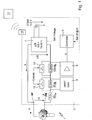
- FIG. 1 shows an embodiment of the field device according to the invention 1.
- the field device 1, an adaptive control of the power supply of the field device 1.
- internal measurement and / or communication resistances in the measuring branch of the I / O module - Rsense, Rcom - are selectively switched on or bridged as required, depending on the respective operating phase.
- the capacity of the power supply unit 5 which is in the case shown is a battery or a battery pack, claimed as little as possible.
- Fig. 1 Shown in Fig. 1 the terminal voltage Ut of the transmitter of the field device 1, the supply voltage Us of the power supply 7, the voltage UBatt of the power source 5 and the voltage drops Uex, Ucom and Usense on the resistors Rex, Rcom, Rsense.
- the Ex limiting resistors Rex typically have values in the range of a few 100 ohms, the HART communication resistor Rcom has at least 250 ohms, and the measuring resistor is between approx. 50 to 100 ohms.
- the voltage surges may be in the range of 6 volts for the Ex limit, 5.5 volts for the communication resistance Rcom and 1-2 volt for the sense resistance. If these voltage drops are added up, the supply voltage Us would have to be 12 V greater than the terminal voltage Ut. Even outside the potentially explosive area, where the resistance Rex can be omitted, the supply voltage Us would still have to be 6V greater than the terminal voltage Ut.
- the supply current It is minimal and thus is usually only 4mA, the difference between the supply voltage Us and the terminal voltage Ut still amounts to just under 2.4 volts.
- the in Fig. 1 shown controller or the control unit 9 of the I / O module 2 knows at any time the current operating phase of the connected field device 1 and the transmitter of the field device 1 and determines the current supply current It.
- the current during the startup phase for booting the field device. 1 is required, the control unit 9 is known.
- the current in the startup phase is set as a parameter.
- control unit 9 switches the measuring resistor Rsense and communication resistor Rcom in dependence on the selectively to each phase of operation of the field device 1, or it bridges one or both resistors; If one of the resistors or both is not needed during the current operating phase, then a corresponding bridging takes place.
- the resistors Rcom and Rsense are switched on or not.
- both resistors are bridged, for example, by switches 12, 13. This bridging continues until the transmitter determines the first regular reading.
- the communication resistor Rcom is bridged. In this case, the flowing measuring current It is measured across the measuring resistor Rsense.
- control unit 9 adaptively changes the required terminal voltage Ut by changing the supply voltage Us as a function of the measured current o.sub.I, depending on the respective operating phase of the transmitter of the field device 1 and depending on the switching state of the resistors Rsense, Rcom Rex changed.
Landscapes
- Physics & Mathematics (AREA)
- General Physics & Mathematics (AREA)
- Engineering & Computer Science (AREA)
- Automation & Control Theory (AREA)
- Arrangements For Transmission Of Measured Signals (AREA)
Claims (14)
- Appareil de terrain (1) autonome de la technique d'automatisation, qui est relié par l'intermédiaire de deux bornes de raccordement (3 et 4) avec un module E/S (2), le module E/S (2) étant conçu en tant que module E/S HART 4-20 mA, une source d'énergie (5, 7) étant attribuée au module E/S (2), source par l'intermédiaire de laquelle l'appareil de terrain (1) est alimenté en énergie, une unité de mesure de courant (6) étant prévue, laquelle détermine le courant mis à la disposition par la source d'énergie (5), des résistances internes (Rex, Rcom, Rsense) étant prévues dans le module E/S (2), aux bornes desquelles apparaît une chute de tension dépendant du courant (It) circulant, et une unité de commande (9) étant prévue pour commander la source d'énergie (5, 7) de telle manière qu'une tension de borne (Ut) prédéfinie, destinée à l'alimentation de l'appareil de terrain (1), soit disponible aux bornes de raccordement (3),
caractérisé en ce que l'unité de commande (9) commande la source d'énergie (5, 7) de telle manière que cette tension de borne (Ut) soit régulée de façon dynamique en fonction du courant (It) circulant, de telle sorte à garantir à tout moment le fonctionnement correct de l'appareil de terrain (1) avec une consommation minimale d'énergie. - Appareil de terrain selon la revendication 1, pour lequel il s'agit, concernant l'unité de mesure de courant (6), d'une résistance de mesure de courant (Rsense), par l'intermédiaire de laquelle le signal 4-20 mA analogique est prélevé.
- Appareil de terrain selon la revendication 1 ou 2, pour lequel il s'agit, concernant les résistances internes, d'une résistance de communication (Rcom), par l'intermédiaire de laquelle le signal de communication (8) numérique est prélevé.
- Appareil de terrain selon la revendication 1 ou 2, pour lequel il s'agit, concernant les résistances internes, d'une résistance limitatrice de courant (Rex), laquelle est dimensionnée de telle manière à répondre aux exigences relatives à une utilisation de l'appareil de terrain (1) dans une zone explosible.
- Appareil de terrain selon la revendication 1, pour lequel il s'agit, concernant le module E/S, d'un adaptateur avec une source d'énergie (5) attribuée.
- Appareil de terrain selon la revendication 1 ou 5, pour lequel il s'agit, concernant le module E/S, d'un adaptateur sans fil, qui communique par le biais d'une unité radio (19) avec un système de commande (11) maître ou un autre appareil de terrain radio.
- Appareil de terrain selon la revendication 1, pour lequel la tension de borne (Ut) prédéfinie est réglable ou prédéfinie de façon fixe.
- Appareil de terrain selon la revendication 1, pour lequel il s'agit, concernant l'appareil de terrain (1), d'un appareil de mesure destiné à ia détermination et/ou à la surveillance d'une grandeur process, d'un actionneur destiné à influencer une grandeur process, d'un appareil d'enregistrement, d'une E/S distante, d'une passerelle ou d'un dispositif de liaison.
- Appareil de terrain selon la revendication 1, pour lequel l'unité de commande (9) exploite de façon intermittente l'appareil de terrain (1) et coupe ou minimise l'alimentation en énergie pendant une phase de repos et qui, pendant une phase de fonctionnement, met à disposition la tension de borne (Ut) prédéfinie pour le fonctionnement de l'appareil de terrain (1).
- Appareil de terrain selon la revendication 1 ou 9, pour lequel l'unité de commande (9) met en/hors circuit, de façon sélective, la résistance de communication (Rcom) et la résistance de mesure de courant (Rsense).
- Appareil de terrain selon la revendication 1 ou 10, pour lequel l'unité de commande (9) court-circuite pendant le démarrage de l'appareil de terrain (1) la résistance de communication (Rcom) et la résistance de mesure de courant (Rsense), jusqu'à ce que l'appareil de terrain (1) soit opérationnel.
- Appareil de terrain selon la revendication 1 ou 3, pour lequel l'unité de commande (9) court-circuite durablement la résistance de communication (Rcom) lorsque l'appareil de terrain (1) met à disposition un signal 4-20 mA analogique.
- Appareil de terrain selon la revendication 1, pour lequel l'unité de commande (9) court-circuite durablement la résistance de mesure de courant (Rsense) lorsque l'appareil de terrain (1) met à disposition un signal de communication numérique sur la base du protocole HART.
- Appareil de terrain selon l'une ou plusieurs des revendications précédentes, pour lequel il s'agit, concernant la source d'énergie (5), d'une batterie, d'une pile à combustible, d'une photopile ou d'un accumulateur.
Applications Claiming Priority (2)
| Application Number | Priority Date | Filing Date | Title |
|---|---|---|---|
| DE102008043199A DE102008043199A1 (de) | 2008-10-27 | 2008-10-27 | Autarkes Feldgerät |
| PCT/EP2009/063181 WO2010049253A1 (fr) | 2008-10-27 | 2009-10-09 | Appareil de terrain autonome |
Publications (2)
| Publication Number | Publication Date |
|---|---|
| EP2340468A1 EP2340468A1 (fr) | 2011-07-06 |
| EP2340468B1 true EP2340468B1 (fr) | 2012-09-19 |
Family
ID=41278342
Family Applications (1)
| Application Number | Title | Priority Date | Filing Date |
|---|---|---|---|
| EP09736198A Active EP2340468B1 (fr) | 2008-10-27 | 2009-10-09 | Appareil de terrain autonome |
Country Status (5)
| Country | Link |
|---|---|
| US (1) | US9442477B2 (fr) |
| EP (1) | EP2340468B1 (fr) |
| CN (1) | CN102197346B (fr) |
| DE (1) | DE102008043199A1 (fr) |
| WO (1) | WO2010049253A1 (fr) |
Cited By (1)
| Publication number | Priority date | Publication date | Assignee | Title |
|---|---|---|---|---|
| EP3894970B1 (fr) * | 2018-12-11 | 2023-10-18 | Endress+Hauser SE+Co. KG | Adaptateur d'appareil de terrain pour la transmission sans fil de données |
Families Citing this family (14)
| Publication number | Priority date | Publication date | Assignee | Title |
|---|---|---|---|---|
| DE102010032831B4 (de) * | 2010-07-30 | 2015-08-20 | Abb Technology Ag | Feldgerät einer Prozessautomatisierungsanlage mit einer eigensicheren Stromversorgungseinrichtung |
| DE102010042717B4 (de) | 2010-10-20 | 2021-12-23 | Endress + Hauser Process Solutions Ag | Anordnung umfassend eine erste und eine zweite Funkeinheit sowie ein Feldgerät und ein Verfahren zum Betreiben derselben |
| US10716488B2 (en) | 2013-12-30 | 2020-07-21 | The University Of Manitoba | Imaging using gated elements |
| DE102014203429A1 (de) * | 2014-02-26 | 2015-08-27 | Siemens Aktiengesellschaft | Redundierbare Eingangsschaltung, Eingangsschaltungseinheit mit mindestens einer Eingangsschaltung und Verfahren zum Betrieb einer solchen Eingangsschaltungseinheit |
| US10197508B2 (en) | 2014-07-07 | 2019-02-05 | Univeristy Of Manitoba | Imaging using reconfigurable antennas |
| DE102014115248A1 (de) | 2014-10-20 | 2016-04-21 | Balluff Gmbh | Sensor-/Aktor-System und Verfahren zum Betreiben eines Sensor-/Aktor-Systems |
| DE102015105887A1 (de) * | 2015-04-17 | 2016-10-20 | Endress + Hauser Process Solutions Ag | Verfahren zum automatischen Hinzu- oder Wegschalten eines Kommunikationswiderstandes eines HART-Gerätes |
| EP3153938B1 (fr) * | 2015-10-06 | 2018-09-26 | VEGA Grieshaber KG | Dispositif de mesure |
| DE102016105362A1 (de) * | 2016-03-22 | 2017-09-28 | Endress+Hauser Gmbh+Co. Kg | Gehäusedeckel für ein Feldgerät der Automatisierungstechnik zum drahtlosen Übermitteln von Informationen |
| BE1025086B1 (nl) * | 2017-03-30 | 2018-10-29 | Smartlog N.V. | Doorsturen van data |
| DE102017114851A1 (de) * | 2017-07-04 | 2019-01-10 | Endress+Hauser SE+Co. KG | Feldgeräteadapter zur drahtlosen Datenübertragung |
| DE102018118706A1 (de) * | 2018-08-01 | 2020-02-06 | Endress+Hauser SE+Co. KG | Zweileiterfeldgerät der Automatisierungstechnik |
| DE102019120918B3 (de) | 2019-08-02 | 2020-12-31 | GFG Gesellschaft für Gerätebau mbH | Signalübertragungssystem |
| DE102021134390A1 (de) * | 2021-12-22 | 2023-06-22 | Endress+Hauser SE+Co. KG | Verfahren zur Regelung des Energieverbrauches eines Feldgeräts der Automatisierungstechnik |
Family Cites Families (17)
| Publication number | Priority date | Publication date | Assignee | Title |
|---|---|---|---|---|
| DE19723645B4 (de) * | 1997-06-05 | 2006-04-13 | Endress + Hauser Gmbh + Co. Kg | Anordnung zur Signalübertragung zwischen einer Geberstelle und einer Empfangsstelle |
| DE19925943A1 (de) * | 1999-06-08 | 2000-12-21 | Krohne Messtechnik Kg | Schaltungsanordnung zur Meßwerterfassung, -übertragung und -auswertung |
| DE10309125B4 (de) * | 2003-02-28 | 2014-01-02 | Endress + Hauser Gmbh + Co. Kg | Vorrichtung und Verfahren zur Spannungsstabilisierung für einen Zweidrahtfeldbus |
| DE102004020393A1 (de) * | 2004-04-23 | 2005-11-10 | Endress + Hauser Gmbh + Co. Kg | Funkmodul für Feldgeräte der Automatisierungstechnik |
| US7200503B2 (en) * | 2004-12-29 | 2007-04-03 | Endrss + Hauser Flowtec Ag | Field device electronics fed by an external electrical energy supply |
| DE102005027047A1 (de) * | 2005-06-10 | 2006-12-14 | Endress + Hauser Wetzer Gmbh + Co. Kg | Messumformerspeisegerät für die Prozessautomatisierungstechnik |
| DE102005063054A1 (de) * | 2005-12-29 | 2007-07-05 | Endress + Hauser Flowtec Ag | Schaltungsanordnung zur Versorgung eines Feldgerätes der Automatisierungstechnik |
| DE102006009979A1 (de) * | 2006-03-03 | 2007-09-06 | Siemens Ag | Einrichtung zur drahtlosen Kommunikation mit einem Feldgerät |
| US7630844B2 (en) * | 2006-07-03 | 2009-12-08 | Endress + Hauser Flowtec Ag | Field device electronics fed by an external electrical energy supply |
| US7844410B2 (en) * | 2006-07-03 | 2010-11-30 | Endress + Hauser Flowtec Ag | Field device electronics fed by an external electrical energy supply |
| DE102006062603A1 (de) * | 2006-12-29 | 2008-07-03 | Endress + Hauser Gmbh + Co. Kg | Verfahren zum Betreiben eines Feldgeräts in zwei Betriebszuständen |
| US20080174178A1 (en) * | 2007-01-22 | 2008-07-24 | Roland Jakobsson | Field bus interface |
| DE102007054923A1 (de) * | 2007-11-15 | 2009-05-20 | Endress + Hauser Process Solutions Ag | Verfahren zum Betreiben eines Feldgerätes |
| DE102007054924A1 (de) * | 2007-11-15 | 2009-05-20 | Endress + Hauser Process Solutions Ag | Verfahren zum Betreiben eines Feldgerätes, sowie Kommunikationseinheit und Feldgerät |
| DE102008054053B4 (de) * | 2008-10-30 | 2013-07-25 | Siemens Aktiengesellschaft | Feldgerät für die Prozessautomatisierung |
| DE102010040866A1 (de) * | 2010-09-16 | 2012-03-22 | Endress + Hauser Gmbh + Co. Kg | Feldgerät zur Bestimmung und/oder Überwachung einer chemischen oder physikalischen Prozessgröße in der Automatisierungstechnik |
| DE102011076708A1 (de) * | 2011-05-30 | 2012-12-06 | Endress + Hauser Process Solutions Ag | Funkeinheit mit einer Versorgungsschaltung zur Spannungsversorgung und Verfahren zum Betreiben einer solchen Funkeinheit |
-
2008
- 2008-10-27 DE DE102008043199A patent/DE102008043199A1/de not_active Withdrawn
-
2009
- 2009-10-09 WO PCT/EP2009/063181 patent/WO2010049253A1/fr not_active Ceased
- 2009-10-09 EP EP09736198A patent/EP2340468B1/fr active Active
- 2009-10-09 CN CN2009801427162A patent/CN102197346B/zh active Active
- 2009-10-09 US US12/451,934 patent/US9442477B2/en active Active
Cited By (1)
| Publication number | Priority date | Publication date | Assignee | Title |
|---|---|---|---|---|
| EP3894970B1 (fr) * | 2018-12-11 | 2023-10-18 | Endress+Hauser SE+Co. KG | Adaptateur d'appareil de terrain pour la transmission sans fil de données |
Also Published As
| Publication number | Publication date |
|---|---|
| EP2340468A1 (fr) | 2011-07-06 |
| WO2010049253A1 (fr) | 2010-05-06 |
| CN102197346A (zh) | 2011-09-21 |
| US9442477B2 (en) | 2016-09-13 |
| DE102008043199A1 (de) | 2010-04-29 |
| CN102197346B (zh) | 2013-12-11 |
| US20110148511A1 (en) | 2011-06-23 |
Similar Documents
| Publication | Publication Date | Title |
|---|---|---|
| EP2340468B1 (fr) | Appareil de terrain autonome | |
| EP1860513B1 (fr) | Circuit destiné à la transmission sécurisée d'une valeur de signal analogique | |
| EP2307934B1 (fr) | Interface universelle pour adaptateur sans fil | |
| DE102004050079B4 (de) | Feldmontiertes Zweileiter-Prozeßgerät | |
| EP2274656B1 (fr) | Appareil de mesure comportant une électronique de mesure et d'exploitation pour le contrôle d'un signal de mesure | |
| EP2220460B1 (fr) | Dispositif de champ pour l'instrumentation d'un processus | |
| DE102013103454A1 (de) | Messumformerspeisegerät, System zum Einsatz in der Automatisierungstechnik, sowie Verfahren zum Bedienen eines solchen Systems | |
| DE102007035710A1 (de) | Messumformer und Stellungsregler zum Anschließen an eine Zweileiter-Stromschleife sowie deren Verwendung | |
| DE102009047535B4 (de) | Verfahren zum Ermitteln einer Anschlusskonfiguration eines Feldgerätes an einem Wireless Adapter | |
| WO2018184766A1 (fr) | Appareil de terrain de la technique d'automatisation à alimentation électrique par câble ethernet | |
| EP3983853B1 (fr) | Appareil de terrain de la technique de l'automatisation | |
| WO2023066590A1 (fr) | Dispositif de terrain pour automatisation à sécurité intrinsèque | |
| WO2021213958A1 (fr) | Dispositif de terrain d'automatisation | |
| WO2021004753A1 (fr) | Procédé de fonctionnement d'un appareil de terrain dans le domaine de l'automatisation | |
| DE102011086054B4 (de) | System zur Sicherstellung der Verfügbarkeit eines Bussystems der Automatisierungstechnik | |
| DE102005043489B4 (de) | Automatisierungstechnische Einrichtung | |
| LU101865B1 (de) | Technik zum Verarbeiten und Austauschen von Signalen zwischen Feldgerät und Steuerung | |
| EP3830656B1 (fr) | Appareil de terrain bifilaire de la technique d'automatisation | |
| DE102005043488A1 (de) | Automatisierungstechnische Einrichtung | |
| DE102017101843A1 (de) | Übertragungssicheres Feldgerät | |
| EP4420208A1 (fr) | Dispositif de terrain pour automatisation à sécurité intrinsèque | |
| WO2025021405A1 (fr) | Adaptateur de dispositif de terrain pour transfert de données sans fil | |
| DE102019125150A1 (de) | Feldgerät |
Legal Events
| Date | Code | Title | Description |
|---|---|---|---|
| PUAI | Public reference made under article 153(3) epc to a published international application that has entered the european phase |
Free format text: ORIGINAL CODE: 0009012 |
|
| 17P | Request for examination filed |
Effective date: 20110228 |
|
| AK | Designated contracting states |
Kind code of ref document: A1 Designated state(s): AT BE BG CH CY CZ DE DK EE ES FI FR GB GR HR HU IE IS IT LI LT LU LV MC MK MT NL NO PL PT RO SE SI SK SM TR |
|
| AX | Request for extension of the european patent |
Extension state: AL BA RS |
|
| DAX | Request for extension of the european patent (deleted) | ||
| GRAP | Despatch of communication of intention to grant a patent |
Free format text: ORIGINAL CODE: EPIDOSNIGR1 |
|
| GRAS | Grant fee paid |
Free format text: ORIGINAL CODE: EPIDOSNIGR3 |
|
| GRAA | (expected) grant |
Free format text: ORIGINAL CODE: 0009210 |
|
| AK | Designated contracting states |
Kind code of ref document: B1 Designated state(s): AT BE BG CH CY CZ DE DK EE ES FI FR GB GR HR HU IE IS IT LI LT LU LV MC MK MT NL NO PL PT RO SE SI SK SM TR |
|
| REG | Reference to a national code |
Ref country code: GB Ref legal event code: FG4D Free format text: NOT ENGLISH |
|
| REG | Reference to a national code |
Ref country code: CH Ref legal event code: EP |
|
| REG | Reference to a national code |
Ref country code: IE Ref legal event code: FG4D Free format text: LANGUAGE OF EP DOCUMENT: GERMAN |
|
| REG | Reference to a national code |
Ref country code: AT Ref legal event code: REF Ref document number: 576312 Country of ref document: AT Kind code of ref document: T Effective date: 20121015 |
|
| REG | Reference to a national code |
Ref country code: DE Ref legal event code: R096 Ref document number: 502009004782 Country of ref document: DE Effective date: 20121115 |
|
| PG25 | Lapsed in a contracting state [announced via postgrant information from national office to epo] |
Ref country code: NO Free format text: LAPSE BECAUSE OF FAILURE TO SUBMIT A TRANSLATION OF THE DESCRIPTION OR TO PAY THE FEE WITHIN THE PRESCRIBED TIME-LIMIT Effective date: 20121219 Ref country code: HR Free format text: LAPSE BECAUSE OF FAILURE TO SUBMIT A TRANSLATION OF THE DESCRIPTION OR TO PAY THE FEE WITHIN THE PRESCRIBED TIME-LIMIT Effective date: 20120919 Ref country code: FI Free format text: LAPSE BECAUSE OF FAILURE TO SUBMIT A TRANSLATION OF THE DESCRIPTION OR TO PAY THE FEE WITHIN THE PRESCRIBED TIME-LIMIT Effective date: 20120919 Ref country code: LT Free format text: LAPSE BECAUSE OF FAILURE TO SUBMIT A TRANSLATION OF THE DESCRIPTION OR TO PAY THE FEE WITHIN THE PRESCRIBED TIME-LIMIT Effective date: 20120919 |
|
| REG | Reference to a national code |
Ref country code: NL Ref legal event code: VDEP Effective date: 20120919 |
|
| REG | Reference to a national code |
Ref country code: LT Ref legal event code: MG4D Effective date: 20120919 |
|
| PG25 | Lapsed in a contracting state [announced via postgrant information from national office to epo] |
Ref country code: LV Free format text: LAPSE BECAUSE OF FAILURE TO SUBMIT A TRANSLATION OF THE DESCRIPTION OR TO PAY THE FEE WITHIN THE PRESCRIBED TIME-LIMIT Effective date: 20120919 Ref country code: SE Free format text: LAPSE BECAUSE OF FAILURE TO SUBMIT A TRANSLATION OF THE DESCRIPTION OR TO PAY THE FEE WITHIN THE PRESCRIBED TIME-LIMIT Effective date: 20120919 Ref country code: GR Free format text: LAPSE BECAUSE OF FAILURE TO SUBMIT A TRANSLATION OF THE DESCRIPTION OR TO PAY THE FEE WITHIN THE PRESCRIBED TIME-LIMIT Effective date: 20121220 Ref country code: SI Free format text: LAPSE BECAUSE OF FAILURE TO SUBMIT A TRANSLATION OF THE DESCRIPTION OR TO PAY THE FEE WITHIN THE PRESCRIBED TIME-LIMIT Effective date: 20120919 |
|
| BERE | Be: lapsed |
Owner name: ENDRESS + HAUSER PROCESS SOLUTIONS A.G. Effective date: 20121031 |
|
| PG25 | Lapsed in a contracting state [announced via postgrant information from national office to epo] |
Ref country code: NL Free format text: LAPSE BECAUSE OF FAILURE TO SUBMIT A TRANSLATION OF THE DESCRIPTION OR TO PAY THE FEE WITHIN THE PRESCRIBED TIME-LIMIT Effective date: 20120919 Ref country code: EE Free format text: LAPSE BECAUSE OF FAILURE TO SUBMIT A TRANSLATION OF THE DESCRIPTION OR TO PAY THE FEE WITHIN THE PRESCRIBED TIME-LIMIT Effective date: 20120919 Ref country code: IS Free format text: LAPSE BECAUSE OF FAILURE TO SUBMIT A TRANSLATION OF THE DESCRIPTION OR TO PAY THE FEE WITHIN THE PRESCRIBED TIME-LIMIT Effective date: 20130119 Ref country code: CZ Free format text: LAPSE BECAUSE OF FAILURE TO SUBMIT A TRANSLATION OF THE DESCRIPTION OR TO PAY THE FEE WITHIN THE PRESCRIBED TIME-LIMIT Effective date: 20120919 Ref country code: RO Free format text: LAPSE BECAUSE OF FAILURE TO SUBMIT A TRANSLATION OF THE DESCRIPTION OR TO PAY THE FEE WITHIN THE PRESCRIBED TIME-LIMIT Effective date: 20120919 |
|
| PG25 | Lapsed in a contracting state [announced via postgrant information from national office to epo] |
Ref country code: SK Free format text: LAPSE BECAUSE OF FAILURE TO SUBMIT A TRANSLATION OF THE DESCRIPTION OR TO PAY THE FEE WITHIN THE PRESCRIBED TIME-LIMIT Effective date: 20120919 Ref country code: PL Free format text: LAPSE BECAUSE OF FAILURE TO SUBMIT A TRANSLATION OF THE DESCRIPTION OR TO PAY THE FEE WITHIN THE PRESCRIBED TIME-LIMIT Effective date: 20120919 Ref country code: MC Free format text: LAPSE BECAUSE OF NON-PAYMENT OF DUE FEES Effective date: 20121031 Ref country code: PT Free format text: LAPSE BECAUSE OF FAILURE TO SUBMIT A TRANSLATION OF THE DESCRIPTION OR TO PAY THE FEE WITHIN THE PRESCRIBED TIME-LIMIT Effective date: 20130121 |
|
| REG | Reference to a national code |
Ref country code: IE Ref legal event code: MM4A |
|
| PLBE | No opposition filed within time limit |
Free format text: ORIGINAL CODE: 0009261 |
|
| STAA | Information on the status of an ep patent application or granted ep patent |
Free format text: STATUS: NO OPPOSITION FILED WITHIN TIME LIMIT |
|
| PG25 | Lapsed in a contracting state [announced via postgrant information from national office to epo] |
Ref country code: BE Free format text: LAPSE BECAUSE OF NON-PAYMENT OF DUE FEES Effective date: 20121031 Ref country code: DK Free format text: LAPSE BECAUSE OF FAILURE TO SUBMIT A TRANSLATION OF THE DESCRIPTION OR TO PAY THE FEE WITHIN THE PRESCRIBED TIME-LIMIT Effective date: 20120919 Ref country code: BG Free format text: LAPSE BECAUSE OF FAILURE TO SUBMIT A TRANSLATION OF THE DESCRIPTION OR TO PAY THE FEE WITHIN THE PRESCRIBED TIME-LIMIT Effective date: 20121219 Ref country code: IE Free format text: LAPSE BECAUSE OF NON-PAYMENT OF DUE FEES Effective date: 20121009 |
|
| 26N | No opposition filed |
Effective date: 20130620 |
|
| PG25 | Lapsed in a contracting state [announced via postgrant information from national office to epo] |
Ref country code: IT Free format text: LAPSE BECAUSE OF FAILURE TO SUBMIT A TRANSLATION OF THE DESCRIPTION OR TO PAY THE FEE WITHIN THE PRESCRIBED TIME-LIMIT Effective date: 20120919 |
|
| REG | Reference to a national code |
Ref country code: DE Ref legal event code: R097 Ref document number: 502009004782 Country of ref document: DE Effective date: 20130620 |
|
| PG25 | Lapsed in a contracting state [announced via postgrant information from national office to epo] |
Ref country code: ES Free format text: LAPSE BECAUSE OF FAILURE TO SUBMIT A TRANSLATION OF THE DESCRIPTION OR TO PAY THE FEE WITHIN THE PRESCRIBED TIME-LIMIT Effective date: 20121230 |
|
| PG25 | Lapsed in a contracting state [announced via postgrant information from national office to epo] |
Ref country code: CY Free format text: LAPSE BECAUSE OF FAILURE TO SUBMIT A TRANSLATION OF THE DESCRIPTION OR TO PAY THE FEE WITHIN THE PRESCRIBED TIME-LIMIT Effective date: 20120919 Ref country code: MT Free format text: LAPSE BECAUSE OF FAILURE TO SUBMIT A TRANSLATION OF THE DESCRIPTION OR TO PAY THE FEE WITHIN THE PRESCRIBED TIME-LIMIT Effective date: 20120919 |
|
| PG25 | Lapsed in a contracting state [announced via postgrant information from national office to epo] |
Ref country code: TR Free format text: LAPSE BECAUSE OF FAILURE TO SUBMIT A TRANSLATION OF THE DESCRIPTION OR TO PAY THE FEE WITHIN THE PRESCRIBED TIME-LIMIT Effective date: 20120919 |
|
| PG25 | Lapsed in a contracting state [announced via postgrant information from national office to epo] |
Ref country code: SM Free format text: LAPSE BECAUSE OF FAILURE TO SUBMIT A TRANSLATION OF THE DESCRIPTION OR TO PAY THE FEE WITHIN THE PRESCRIBED TIME-LIMIT Effective date: 20120919 Ref country code: LU Free format text: LAPSE BECAUSE OF NON-PAYMENT OF DUE FEES Effective date: 20121009 |
|
| REG | Reference to a national code |
Ref country code: CH Ref legal event code: PL |
|
| PG25 | Lapsed in a contracting state [announced via postgrant information from national office to epo] |
Ref country code: CH Free format text: LAPSE BECAUSE OF NON-PAYMENT OF DUE FEES Effective date: 20131031 Ref country code: HU Free format text: LAPSE BECAUSE OF FAILURE TO SUBMIT A TRANSLATION OF THE DESCRIPTION OR TO PAY THE FEE WITHIN THE PRESCRIBED TIME-LIMIT Effective date: 20091009 Ref country code: LI Free format text: LAPSE BECAUSE OF NON-PAYMENT OF DUE FEES Effective date: 20131031 |
|
| PG25 | Lapsed in a contracting state [announced via postgrant information from national office to epo] |
Ref country code: MK Free format text: LAPSE BECAUSE OF FAILURE TO SUBMIT A TRANSLATION OF THE DESCRIPTION OR TO PAY THE FEE WITHIN THE PRESCRIBED TIME-LIMIT Effective date: 20120919 |
|
| REG | Reference to a national code |
Ref country code: FR Ref legal event code: PLFP Year of fee payment: 7 |
|
| REG | Reference to a national code |
Ref country code: AT Ref legal event code: MM01 Ref document number: 576312 Country of ref document: AT Kind code of ref document: T Effective date: 20141009 |
|
| PG25 | Lapsed in a contracting state [announced via postgrant information from national office to epo] |
Ref country code: AT Free format text: LAPSE BECAUSE OF NON-PAYMENT OF DUE FEES Effective date: 20141009 |
|
| PG25 | Lapsed in a contracting state [announced via postgrant information from national office to epo] |
Ref country code: IT Free format text: LAPSE BECAUSE OF FAILURE TO SUBMIT A TRANSLATION OF THE DESCRIPTION OR TO PAY THE FEE WITHIN THE PRESCRIBED TIME-LIMIT Effective date: 20131009 |
|
| REG | Reference to a national code |
Ref country code: FR Ref legal event code: PLFP Year of fee payment: 8 |
|
| PGRI | Patent reinstated in contracting state [announced from national office to epo] |
Ref country code: IT Effective date: 20170105 |
|
| REG | Reference to a national code |
Ref country code: FR Ref legal event code: PLFP Year of fee payment: 9 |
|
| REG | Reference to a national code |
Ref country code: FR Ref legal event code: PLFP Year of fee payment: 10 |
|
| P01 | Opt-out of the competence of the unified patent court (upc) registered |
Effective date: 20230601 |
|
| PGFP | Annual fee paid to national office [announced via postgrant information from national office to epo] |
Ref country code: DE Payment date: 20241021 Year of fee payment: 16 |
|
| PGFP | Annual fee paid to national office [announced via postgrant information from national office to epo] |
Ref country code: GB Payment date: 20241022 Year of fee payment: 16 |
|
| PGFP | Annual fee paid to national office [announced via postgrant information from national office to epo] |
Ref country code: FR Payment date: 20241021 Year of fee payment: 16 |
|
| PGFP | Annual fee paid to national office [announced via postgrant information from national office to epo] |
Ref country code: IT Payment date: 20241025 Year of fee payment: 16 |