EP2340377B1 - Brake disc arrangement for disc brakes - Google Patents
Brake disc arrangement for disc brakes Download PDFInfo
- Publication number
- EP2340377B1 EP2340377B1 EP09764827A EP09764827A EP2340377B1 EP 2340377 B1 EP2340377 B1 EP 2340377B1 EP 09764827 A EP09764827 A EP 09764827A EP 09764827 A EP09764827 A EP 09764827A EP 2340377 B1 EP2340377 B1 EP 2340377B1
- Authority
- EP
- European Patent Office
- Prior art keywords
- friction ring
- brake disc
- connection element
- disc arrangement
- connecting element
- Prior art date
- Legal status (The legal status is an assumption and is not a legal conclusion. Google has not performed a legal analysis and makes no representation as to the accuracy of the status listed.)
- Not-in-force
Links
Images


Classifications
-
- F—MECHANICAL ENGINEERING; LIGHTING; HEATING; WEAPONS; BLASTING
- F16—ENGINEERING ELEMENTS AND UNITS; GENERAL MEASURES FOR PRODUCING AND MAINTAINING EFFECTIVE FUNCTIONING OF MACHINES OR INSTALLATIONS; THERMAL INSULATION IN GENERAL
- F16D—COUPLINGS FOR TRANSMITTING ROTATION; CLUTCHES; BRAKES
- F16D65/00—Parts or details
- F16D65/02—Braking members; Mounting thereof
- F16D65/12—Discs; Drums for disc brakes
- F16D65/123—Discs; Drums for disc brakes comprising an annular disc secured to a hub member; Discs characterised by means for mounting
-
- F—MECHANICAL ENGINEERING; LIGHTING; HEATING; WEAPONS; BLASTING
- F16—ENGINEERING ELEMENTS AND UNITS; GENERAL MEASURES FOR PRODUCING AND MAINTAINING EFFECTIVE FUNCTIONING OF MACHINES OR INSTALLATIONS; THERMAL INSULATION IN GENERAL
- F16D—COUPLINGS FOR TRANSMITTING ROTATION; CLUTCHES; BRAKES
- F16D65/00—Parts or details
- F16D65/02—Braking members; Mounting thereof
- F16D2065/13—Parts or details of discs or drums
- F16D2065/1304—Structure
- F16D2065/1316—Structure radially segmented
-
- F—MECHANICAL ENGINEERING; LIGHTING; HEATING; WEAPONS; BLASTING
- F16—ENGINEERING ELEMENTS AND UNITS; GENERAL MEASURES FOR PRODUCING AND MAINTAINING EFFECTIVE FUNCTIONING OF MACHINES OR INSTALLATIONS; THERMAL INSULATION IN GENERAL
- F16D—COUPLINGS FOR TRANSMITTING ROTATION; CLUTCHES; BRAKES
- F16D65/00—Parts or details
- F16D65/02—Braking members; Mounting thereof
- F16D2065/13—Parts or details of discs or drums
- F16D2065/1304—Structure
- F16D2065/1328—Structure internal cavities, e.g. cooling channels
-
- F—MECHANICAL ENGINEERING; LIGHTING; HEATING; WEAPONS; BLASTING
- F16—ENGINEERING ELEMENTS AND UNITS; GENERAL MEASURES FOR PRODUCING AND MAINTAINING EFFECTIVE FUNCTIONING OF MACHINES OR INSTALLATIONS; THERMAL INSULATION IN GENERAL
- F16D—COUPLINGS FOR TRANSMITTING ROTATION; CLUTCHES; BRAKES
- F16D65/00—Parts or details
- F16D65/02—Braking members; Mounting thereof
- F16D2065/13—Parts or details of discs or drums
- F16D2065/134—Connection
- F16D2065/1344—Connection permanent, e.g. by casting
-
- F—MECHANICAL ENGINEERING; LIGHTING; HEATING; WEAPONS; BLASTING
- F16—ENGINEERING ELEMENTS AND UNITS; GENERAL MEASURES FOR PRODUCING AND MAINTAINING EFFECTIVE FUNCTIONING OF MACHINES OR INSTALLATIONS; THERMAL INSULATION IN GENERAL
- F16D—COUPLINGS FOR TRANSMITTING ROTATION; CLUTCHES; BRAKES
- F16D65/00—Parts or details
- F16D65/02—Braking members; Mounting thereof
- F16D2065/13—Parts or details of discs or drums
- F16D2065/134—Connection
- F16D2065/1356—Connection interlocking
- F16D2065/136—Connection interlocking with relative movement radially
-
- F—MECHANICAL ENGINEERING; LIGHTING; HEATING; WEAPONS; BLASTING
- F16—ENGINEERING ELEMENTS AND UNITS; GENERAL MEASURES FOR PRODUCING AND MAINTAINING EFFECTIVE FUNCTIONING OF MACHINES OR INSTALLATIONS; THERMAL INSULATION IN GENERAL
- F16D—COUPLINGS FOR TRANSMITTING ROTATION; CLUTCHES; BRAKES
- F16D2250/00—Manufacturing; Assembly
- F16D2250/0007—Casting
Description
Die vorliegende Erfindung betrifft eine Bremsscheibenanordnung für Scheibenbremsen, beispielsweise von Landfahrzeugen (wie Personenkraftwagen, Lastkraftwagen, Nutzfahrzeugen oder Anhängern) sowie ein Verfahren zur Herstellung einer Bremsscheibenanordnung für Scheibenbremsen, ebenfalls insbesondere für Landfahrzeuge.The present invention relates to a disc brake assembly for disc brakes, such as land vehicles (such as passenger cars, trucks, commercial vehicles or trailers) and a method for producing a brake disc assembly for disc brakes, also particularly for land vehicles.
Bremsscheibenanordnungen der in Rede stehenden Art sind aus dem Stand der Technik bekannt. So offenbart beispielsweise die
Die
Die
Es ist somit Aufgabe der vorliegenden Erfindung, eine Bremsscheibenanordnung für Scheibenbremsen, insbesondere für Landfahrzeuge, sowie ein Verfahren zur Herstellung einer Bremsscheibenanordnung für Scheibenbremsen, insbesondere für Landfahrzeuge, vorzusehen, mittels welchen die Betriebssicherheit der Bremsscheibenanordnung verbessert und der Produktionsprozess vereinfacht sowie die Produktionskosten verringert werden können.It is therefore an object of the present invention to provide a brake disc assembly for disc brakes, especially for land vehicles, and a method for producing a brake disc assembly for disc brakes, especially for land vehicles, by means of which the reliability of Improved brake disc assembly and the production process can be simplified and the production costs can be reduced.
Diese Aufgabe wird durch eine Bremsscheibenanordnung für Scheibenbremsen, insbesondere für Landfahrzeuge, mit den Merkmalen des Anspruchs 1 sowie durch ein Verfahren zur Herstellung einer Bremsscheibenanordnung für Scheibenbremsen, insbesondere für Landfahrzeuge, mit den Merkmalen des Anspruchs 13 gelöst. Bevorzugte Ausführungsformen sind Gegenstand der abhängigen Ansprüche.This object is achieved by a disc brake assembly for disc brakes, in particular for land vehicles, with the features of claim 1 and by a method for producing a brake disc assembly for disc brakes, in particular for land vehicles, having the features of claim 13. Preferred embodiments are subject of the dependent claims.
Erfindungsgemäß ist eine Bremsscheibenanordnung für Scheibenbremsen, insbesondere für Landfahrzeuge, vorgesehen, umfassend einen Reibring, einen Anbindungsadapter zur Anbindung der Bremsscheibenanordnung an eine Radnabe, und zumindest ein Verbindungselement zur Verbindung von Reibring und Anbindungsadapter, wobei der Anbindungsadapter einen Befestigungsbereich aufweist, in welchem das Verbindungselement ortsfest befestigt ist, und wobei der Reibring einen Aufnahmebereich aufweist, in welchem das Verbindungselement derart aufgenommen ist, dass der Reibring auf bzw. in Bezug zu dem Verbindungselement radial beweglich ist. Die Bremsscheibenanordnung ist somit zweckmäßigerweise für Bremsscheiben vorgesehen, deren Reibring entweder massiv (das heißt ohne Belüftungskanäle bzw. Zirkulationsraum) oder als innenbelüfteter Reibring (mit Zirkulationsraum bzw. Belüftungskammern) ausgebildet ist. Die Bremsscheibenanordnung dient insbesondere der Anordnung an Landfahrzeugen, wie beispielsweise Pkw, Lkw, Anhänger, Züge oder Ähnlichem, soll jedoch nicht auf die vorgenannte Aufzählung beschränkt sein. Die Bremsscheibenanordnung ist ausgelegt, mit dem Rad oder einer Radnabe mittelbar oder unmittelbar befestigt zu werden, sodass diese mit dem Rad umläuft. An den Reibring können zum Abbremsen des Rades von beiden Seiten Bremsbeläge gepresst werden, welche in einem Bremssattel vorgesehen sind, der den Reibring umspannt. Die Bremsscheibenanordnung weist weiterhin zweckmäßigerweise einen Anbindungsadapter auf, welcher ausgelegt ist, die Bremsscheibenanordnung an eine Radnabe anzubinden. Die Anbindung kann hierbei mittelbar über zwischengeschaltete Elemente oder unmittelbar an die Radnabe erfolgen. Es versteht sich, dass der Anbindungsadapter einen topfförmigen Abschnitt aufweisen kann, welcher mit dem Rad oder der Radnabe verbunden ist. Ebenfalls kann der Anbindungsadapter Teil der Radnabe selbst sein. Weiterhin vorgesehen ist zumindest ein Verbindungselement zur Verbindung von Reibring und Anbindungsadapter. Das Verbindungselement ist somit ausgelegt, Reibring und Anbindungsadapter derart miteinander zu verbinden, dass diese axial (das heißt in Richtung der Rotationsachse der Bremsscheibenanordnung gesehen) und in umfänglicher Rotationsrichtung der Bremsscheibenanordnung nicht oder nur geringfügig zueinander beweglich sind, um Kräfte von dem Reibring auf den Anbindungsadapter zu übertragen. Reibring und Anbindungsadapter sind somit derart als getrennte Teile voneinander ausgebildet, dass sie im Wesentlichen durch einen Ringspalt voneinander getrennt sind und untereinander lediglich durch das zumindest eine Verbindungselement miteinander verbunden sind, von welchem ein erstes Ende bzw. ein erster Bereich mit dem Anbindungsadapter in Eingriff steht und von welchem ein zweites Ende bzw. zweiter Bereich mit dem Reibring in Eingriff steht. Hierfür weist der Anbindungsadapter einen Befestigungsbereich auf, in welchem das Verbindungselement ortsfest befestigt ist. Der Befestigungsbereich im Anwendungsadapter kann insbesondere als sich radial zur Rotationsachse der Bremsscheibenanordnung erstreckender Rücksprung in dem Anbindungsadapter ausgebildet sein. Das erste Ende des Verbindungselements ist in dem Befestigungsbereich des Anbindungsadapters derart ortsfest befestigt, dass - selbst bei großer Temperatureinwirkung - eine (vorzugsweise radiale) Relativbewegung von Verbindungselement zu Anbindungsadapter nicht möglich ist. Zweckmäßigerweise weist der Reibring einen Aufnahmebereich auf, in welchem das Verbindungselement derart aufgenommen ist, dass der Reibring auf bzw. in Bezug zu dem Verbindungselement radial beweglich ist. Der Aufnahmebereich des Reibrings kann als sich vom Innenumfang desselben radial in diesen hinein erstreckender Rücksprung ausgebildet sein. Hierin ist der zweite Bereich bzw. das zweite Ende bzw. gegenüberliegende Bereich bzw. Ende des Verbindungselements derart aufgenommen bzw. eingebettet, dass eine Relativbewegung zwischen dem Verbindungselement und dem Reibring in Radialrichtung der Bremsscheibenanordnung möglich ist. In anderen Worten sind Verbindungselement und Reibring derart miteinander verbunden, dass eine Bewegung zwischen Verbindungselement (und somit Anbindungsadapter) und Reibring in axialer Richtung oder umfänglicher Rotationsrichtung der Bremsscheibenanordnung nicht oder nur geringfügig zugelassen wird. Jedoch ist es dem Reibring möglich, in radialer Richtung der Bremsscheibenanordnung bzw. in Längsrichtung bzw. parallel bzw. entlang der Längsachse des Verbindungselements zu gleiten bzw. sich zu bewegen. Dieser Effekt wird insbesondere während des Bremsvorgangs aufgrund der unterschiedlichen Temperaturniveaus in der Bremsscheibenanordnung ermöglicht bzw. verstärkt. Hierbei weist der Reibring die größte Temperatur auf, gefolgt von der Temperatur des Verbindungselements und des Anbindungsadapters, wobei die Temperatur des Anbindungsadapters am geringsten ist. Infolgedessen dehnt sich der Reibring stärker als das Verbindungselement aus, so dass im Aufnahmebereich ein Spalt zwischen dem zweiten Ende des Verbindungselements und dem Reibring auftritt, welcher ein freies Gleiten bzw. eine Bewegung in radialer Richtung zulässt. Da das Verbindungselement wärmer als der Anbindungsadapter ist, dehnt sich dieses im Befestigungsbereich stärker als der Anbindungsadapter aus, so dass die Verbindung zwischen dem Verbindungselement und Anbindungsadapter aufgrund von einem erhöhten Presssitz während des Bremsvorgangs noch stärker wird. Besonders vorteilhafterweise ist das Verbindungselement aus einem anderen Material als der Anbindungsadapter und der Reibring ausgebildet. Besonders zweckmäßigerweise ist der Reibring aus einem Gussmaterial, wie Grauguss, oder einem Keramikwerkstoff hergestellt. Der Anbindungsadapter kann ebenfalls aus einem Gussmaterial hergestellt sein, vorzugsweise Grauguss, und ist besonders vorteilhafterweise aus dem gleichen Material wie der Reibring hergestellt. Das Verbindungselement ist zweckmäßigerweise aus Stahl oder Ähnlichem ausgebildet. Durch die erfindungsgemäße Bremsscheibenanordnung wird somit sichergestellt, dass sich der - sehr heiße - Reibring radial frei ausdehnen kann und somit ein Aufschirmen vermieden wird, wodurch die Betriebssicherheit der Bremsscheibenanordnung deutlich verbessert werden kann. Zweckmäßigerweise ist eine Vielzahl von vorzugsweise gleichmäßig über den Umfang des Anbindungsadapters angeordneten Verbindungselementen vorgesehen. Hierbei können die Verbindungselemente entlang des Außenumfangs des Anbindungsadapters bzw. Innenumfangs des Reibrings angeordnet sein. Um Kräfte optimal zwischen Reibring und Anbindungsadapter verteilen zu können, ist es besonders bevorzugt, wenn die Vielzahl der Verbindungselemente gleichmäßig in umfänglicher Richtung verteilt ist. Besonders zweckmäßigerweise sind acht bis zwölf Verbindungselemente vorgesehen. Besonders vorzugsweise sind zehn Verbindungselemente vorgesehen. Bei Kraftfahrzeugen ist es besonders vorteilhaft, wenn die gleiche Anzahl wie Befestigungselemente für Räder oder ein Vielfaches davon vorgesehen sind, d. h. bei beispielsweise fünf Radbolzen, fünf, zehn oder fünfzehn Verbindungselemente.According to the invention, a brake disc arrangement for disc brakes, in particular for land vehicles, is provided, comprising a friction ring, a connection adapter for connecting the brake disc arrangement to a wheel hub, and at least one connecting element for connecting friction ring and connection adapter, wherein the connection adapter has a fastening region in which the connecting element is stationary is fixed, and wherein the friction ring has a receiving area in which the connecting element is received such that the friction ring is on or in relation to the connecting element radially movable. The brake disk assembly is thus expediently provided for brake disks whose friction ring is formed either solid (that is, without ventilation channels or circulation space) or as an internally ventilated friction ring (with circulation space or ventilation chambers). The brake disk assembly is used in particular the arrangement of land vehicles, such as cars, trucks, trailers, trains or the like, but should not be limited to the above list. The brake disc assembly is designed to be directly or indirectly attached to the wheel or hub so that it rotates with the wheel. On the friction ring brake pads can be pressed to brake the wheel from both sides, which are provided in a caliper that spans the friction ring. The brake disk assembly further expediently has a connection adapter, which is designed to connect the brake disk assembly to a wheel hub. The connection can hereby indirectly via intermediate elements or directly to the Wheel hub done. It is understood that the connection adapter may have a pot-shaped portion which is connected to the wheel or the wheel hub. Also, the connection adapter may be part of the wheel hub itself. Also provided is at least one connecting element for connecting the friction ring and the connection adapter. The connecting element is thus designed to connect the friction ring and the connection adapter with one another in such a way that they are not or only slightly movable relative to one another in the circumferential direction of rotation of the brake disk arrangement (in the direction of the axis of rotation of the brake disk arrangement) in order to move forces from the friction ring to the connection adapter transferred to. Friction ring and connection adapters are thus formed as separate parts from each other, that they are substantially separated by an annular gap and are interconnected only by the at least one connecting element, of which a first end or a first region is in engagement with the connection adapter and of which a second end or second region is engaged with the friction ring. For this purpose, the connection adapter has a fastening region in which the connecting element is fixed in place. The attachment area in the application adapter can be designed, in particular, as a recess extending radially to the axis of rotation of the brake disk arrangement in the connection adapter. The first end of the connecting element is fixed in a fixed manner in the fastening region of the connection adapter such that a (preferably radial) relative movement of the connecting element to the connection adapter is not possible, even if the temperature is high. Expediently, the friction ring has a receiving region in which the connecting element is received in such a way that the friction ring is radially movable on or in relation to the connecting element. The receiving region of the friction ring can be configured as a recess extending radially from the inner circumference of the latter. Herein, the second region or the second end or opposite region or end of the connecting element is received or embedded such that a relative movement between the connecting element and the friction ring in the radial direction of the brake disc assembly is possible. In other words Connecting element and friction ring connected to each other such that a movement between the connecting element (and thus connection adapter) and friction ring in the axial direction or circumferential direction of rotation of the brake disc assembly is not or only slightly allowed. However, it is possible for the friction ring to slide or to move in the radial direction of the brake disk arrangement or in the longitudinal direction or parallel or along the longitudinal axis of the connecting element. This effect is enabled or enhanced, in particular, during the braking process on account of the different temperature levels in the brake disk arrangement. Here, the friction ring has the highest temperature, followed by the temperature of the connecting element and the connection adapter, wherein the temperature of the connection adapter is the lowest. As a result, the friction ring expands more than the connecting element, so that in the receiving area, a gap between the second end of the connecting element and the friction ring occurs, which allows free sliding or movement in the radial direction. Since the connecting element is warmer than the connecting adapter, it expands more strongly in the fastening area than the connecting adapter, so that the connection between the connecting element and connecting adapter becomes even stronger due to an increased interference fit during the braking process. Particularly advantageously, the connecting element is formed from a different material than the connection adapter and the friction ring. Particularly suitably, the friction ring is made of a cast material, such as gray cast iron, or a ceramic material. The connection adapter may also be made of a cast material, preferably gray cast iron, and is most advantageously made of the same material as the friction ring. The connecting element is expediently made of steel or the like. The brake disk assembly according to the invention thus ensures that the - very hot - friction ring can expand radially freely and thus shielding is avoided, whereby the reliability of the brake disk assembly can be significantly improved. Conveniently, a plurality of preferably uniformly arranged over the circumference of the connection adapter connecting elements is provided. Here, the connecting elements along the outer periphery of the Connection adapter or inner circumference of the friction ring may be arranged. In order to be able to optimally distribute forces between the friction ring and the connection adapter, it is particularly preferred if the plurality of connection elements is distributed uniformly in the circumferential direction. Particularly expediently, eight to twelve connecting elements are provided. Particularly preferably, ten connecting elements are provided. In motor vehicles, it is particularly advantageous if the same number as fasteners for wheels or a multiple thereof are provided, ie, for example, five wheel bolts, five, ten or fifteen fasteners.
Vorzugsweise sind der Reibring und der Anbindungsadapter im Wesentlichen konzentrisch zueinander um die Rotationsachse der Bremsscheibenanordnung angeordnet. In anderen Worten sind Reibring und Anbindungsadapter derart zueinander angeordnet, dass der Reibring den Anbindungsadapter zumindest teilweise umgibt bzw. umschließt. Besonders vorzugsweise sind der Aufnahmebereich des Reibrings und der Befestigungsbereich des Anbindungsadapters im Wesentlichen auf einer senkrecht zur Rotationsachse der Bremsscheibenanordnung gelegenen Ebene angeordnet. In anderen Worten können der Aufnahmebereich des Reibrings und ein korrespondierender Befestigungsbereich des Anbindungsadapters entlang einer radialen Linie der Bremsscheibenanordnung angeordnet sein.Preferably, the friction ring and the connection adapter are arranged substantially concentrically with each other about the axis of rotation of the brake disk assembly. In other words, the friction ring and the connection adapter are arranged relative to one another such that the friction ring at least partially surrounds or surrounds the connection adapter. Particularly preferably, the receiving region of the friction ring and the attachment region of the attachment adapter are arranged substantially on a plane perpendicular to the axis of rotation of the brake disc assembly plane. In other words, the receiving region of the friction ring and a corresponding fastening region of the connection adapter can be arranged along a radial line of the brake disk arrangement.
Vorzugsweise ist das Verbindungselement als länglicher Körper ausgebildet, dessen Längsachse vorzugsweise senkrecht zur Rotationsachse der Bremsscheibenanordnung steht. Es versteht sich, dass das Verbindungselement jedoch nicht zwingend eine Länge aufweisen muss, die größer als die Erstreckung in Querschnittsrichtung ist. Die Längsachse des Verbindungselements ist vorzugsweise senkrecht zur Rotationsachse der Bremsscheibenanordnung. In anderen Worten steht die Längsachse des Verbindungselements im Wesentlichen parallel zu einer radialen Linie der Bremsscheibenanordnung oder fluchet bzw. stimmt mit dieser überein.Preferably, the connecting element is designed as an elongate body whose longitudinal axis is preferably perpendicular to the axis of rotation of the brake disc assembly. It is understood, however, that the connecting element does not necessarily have to have a length which is greater than the extent in the cross-sectional direction. The longitudinal axis of the connecting element is preferably perpendicular to the axis of rotation of the brake disc assembly. In other words, the longitudinal axis of the connecting element is substantially parallel to a radial line of the brake disc assembly or cursing or agrees with this.
Besonders vorteilhafterweise ist das Verbindungselement zumindest teilweise als zylindrischer Körper ausgebildet, der vorzugsweise einen runden, besonders vorzugsweise kreisrunden Querschnitt aufweist. Das Verbindungselement ist somit entlang seiner Längsachse bzw. Längserstreckung zumindest teilweise, vorzugsweise vollständig als zylindrischer Körper ausgebildet. Hierbei kann das Verbindungselement einen runden, zweckmäßigerweise kreisrunden Querschnitt aufweisen. Der Querschnitt steht hierbei im Wesentlichen senkrecht zur Längsachse bzw. Längserstreckung des Verbindungselements. Infolgedessen kann das Verbindungselement im Querschnitt eine ovale oder kreisrunde Form aufweisen. Besonders vorteilhaft ist die kreisrunde Querschnittsform des Verbindungselements, zumindest im Bereich der Anordnung desselben im Reibring und dem Anbindungsadapter, da hierdurch die Montage bei einem mehrstufigen Gussverfahren vereinfacht werden kann. Es versteht sich, dass das Verbindungselement im Querschnitt auch eine beliebig andere eckige Konfiguration besitzen kann, beispielsweise viereckig, rautenförmig, dreieckig oder vieleckig.Particularly advantageously, the connecting element is at least partially formed as a cylindrical body, which preferably has a round, particularly preferably circular cross-section. The connecting element is thus at least partially, preferably completely, formed as a cylindrical body along its longitudinal axis or longitudinal extent. Here, the connecting element may have a round, expediently circular cross-section. The cross section is in this case substantially perpendicular to the longitudinal axis or longitudinal extension of the connecting element. As a result, the connecting element may have an oval or circular shape in cross section. Particularly advantageous is the circular cross-sectional shape of the connecting element, at least in the region of the same arrangement in the friction ring and the connection adapter, since this assembly can be simplified in a multi-stage casting process. It is understood that the connecting element in cross-section may also have any other angular configuration, for example, quadrangular, diamond-shaped, triangular or polygonal.
Zweckmäßigerweise ist das Verbindungselement zumindest teilweise als sich zum Reibring verjüngender Körper ausgebildet. Das Verbindungselement kann somit entlang seiner gesamten Längserstreckung oder nur entlang eines Teilbereichs als sich zum Reibring hin verjüngender bzw. konischer Körper ausgebildet sein. In anderen Worten verjüngt sich das Verbindungselement ausgehend vom Anbindungsadapter in Richtung des Reibrings. Die Verjüngung kann besonders vorteilhafterweise konstant bzw. linear verjüngend ausgebildet sein. Es versteht sich, dass die Querschnittsabnahme in Längsrichtung des Verbindungselements auch nicht konstant bzw. nicht linear vorgesehen sein kann. Hierbei kann die Verjüngung auch lediglich im Bereich der Anbindung an den Reibring vorgesehen sein. Beispielsweise kann sich an den sich verjüngenden Bereich, welcher im Bereich der Anbindung an den Reibring vorgesehen ist, ein zylindrischer Bereich mit konstantem Querschnitt anschließen, der vorzugsweise von einem sich wiederum verjüngenden Bereich zu dem Anbindungsadapter hin gefolgt ist, so dass sich eine Art Doppelkonus ergibt.Conveniently, the connecting element is at least partially designed as a body tapering towards the friction ring. The connecting element can thus be designed along its entire longitudinal extension or only along a partial region as a tapering or conical body towards the friction ring. In other words, the connecting element tapers starting from the connection adapter in the direction of the friction ring. The taper may be formed particularly advantageously constant or linearly tapered. It is understood that the cross-section decrease in the longitudinal direction of the connecting element can not be provided constant or non-linear. In this case, the taper can also be provided only in the region of the connection to the friction ring. For example, adjoin the tapered region, which is provided in the region of the connection to the friction ring, a cylindrical region with a constant cross-section, which is preferably followed by a re-tapering region to the connection adapter out, so that there is a kind of double cone ,
In einer bevorzugten Ausführungsform ist das Verbindungselement als Hohlkörper ausgebildet. Das Verbindungselement kann somit entweder als massiver Körper oder als Hohlkörper ausgebildet sein. Bei einer hohlen Ausbildung des Verbindungselements ist dieses zweckmäßigerweise als Art Buchse oder Hülse ausgebildet und weist somit ein Durchgangsloch entlang der Längserstreckung des Verbindungselements auf.In a preferred embodiment, the connecting element is designed as a hollow body. The connecting element can thus be designed either as a solid body or as a hollow body. In a hollow design of the connecting element this is expediently designed as a type of bush or sleeve and thus has a through hole along the longitudinal extent of the connecting element.
Zweckmäßigerweise weist das Verbindungselement zumindest einen sich in Richtung dessen Längsachse erstreckenden Rücksprung auf, welcher in einem Bodenabschnitt des Verbindungselements endet. Der Rücksprung kann somit als Ausnehmung oder Vertiefung ausgebildet sein, so dass das Verbindungselement besonders vorteilhafterweise becherförmig ausgebildet ist. Der Querschnitt - senkrecht zur Längsachse des Verbindungselements gesehen - kann beliebig ausgestaltet sein, weist jedoch besonders vorteilhafterweise die gleiche Querschnittskonfiguration auf, wie der Außenquerschnitt des Verbindungselements. Besonders zweckmäßigerweise ist der Querschnitt des Rücksprungs rund, insbesondere kreisförmig ausgebildet. Das Querschnittsflächenverhältnis des Rücksprungs zu dem Verbindungselement (Querschnittsfläche des Verbindungselements inklusive Rücksprung) beträgt etwa mindestens 0,25, vorzugsweise etwa mindestens 0,4 und besonders vorzugsweise etwa mindestens 0,6. Die Tiefe des Rücksprungs (in Richtung der Längsachse gesehen) beträgt vorteilhafterweise etwa zumindest 0,35, vorzugsweise etwa zumindest 0,6 und besonders vorzugsweise etwa zumindest 0,85 der gesamten Längserstreckung des Verbindungselements. In einer vorteilhaften Ausbildung ist die (in Richtung der Längsachse gesehen) Dicke des Bodenabschnitts etwa gleich der Wandstärke der Mantelfläche des Verbindungselements ausgebildet.Conveniently, the connecting element has at least one recess extending in the direction of its longitudinal axis, which ends in a bottom section of the connecting element. The recess can thus be formed as a recess or depression, so that the connecting element is particularly advantageously formed cup-shaped. The cross-section - seen perpendicular to the longitudinal axis of the connecting element - may be configured as desired, but particularly advantageously has the same cross-sectional configuration as the outer cross section of the connecting element. Particularly expediently, the cross section of the recess is round, in particular circular. The cross-sectional area ratio of the recess to the connecting element (cross-sectional area of the connecting element including return) is about at least 0.25, preferably about at least 0.4 and more preferably about at least 0.6. The depth of the recess (viewed in the direction of the longitudinal axis) is advantageously approximately at least 0.35, preferably approximately at least 0.6 and particularly preferably approximately at least 0.85 of the entire longitudinal extension of the connecting element. In an advantageous embodiment, the (seen in the direction of the longitudinal axis) thickness of the bottom portion is formed approximately equal to the wall thickness of the lateral surface of the connecting element.
Vorteilhafterweise ist das Verbindungselement derart angeordnet, dass sich der Rücksprung zu dem Reibring oder dem Anbindungsadapter hin öffnet. In anderen Worten erstreckt sich der Rücksprung von dem Reibring aus in das Verbindungselement hinein bzw. von dem Anbindungsadapter aus in das Verbindungselement hinein. Bei einer Konfiguration, bei welcher sich der Rücksprung zu dem Anbindungsadapter hin öffnet, kann der Rücksprung vollständig durch das Material des Anbindungsadapters gefüllt sein. Alternativ kann der Rücksprung nicht vom Material des Anbindungsadapters ausgefüllt sein, wobei besonders zweckmäßigerweise eine radiale Durchgangsöffnung zu dem Innenumfang des Anbindungsadapters vorgesehen ist. Weiterhin alternativ kann sich das Material des Anbindungsadapters zumindest teilweise in den Rücksprung hinein erstrecken. Entsprechende Alternativlösungen können bei einer Öffnung des Rücksprungs zu dem Reibring hin vorgesehen sein, so dass das Material des Reibrings sich zweckmäßigerweise nicht in den Rücksprung hinein erstreckt, wobei in einer derartigen Ausführungsform besonders vorteilhafterweise eine Zirkulationsverbindung zwischen dem Zirkulationsraum des Reibrings und dem Rücksprung vorgesehen ist. Durch diese Konfiguration wird eine optimierte Kühlung der Bremsscheibe aufgrund der Oberflächenvergrößerung an den Verbindungselementen ermöglicht.Advantageously, the connecting element is arranged such that the return to the friction ring or the connection adapter opens. In other words, the recess extends from the friction ring into the connection element or into the connection element from the connection adapter. In a configuration in which the Return to the connection adapter opens, the return may be completely filled by the material of the connection adapter. Alternatively, the return can not be filled by the material of the connection adapter, wherein a radial passage opening to the inner circumference of the connection adapter is particularly expediently provided. Furthermore, alternatively, the material of the connection adapter may extend at least partially into the recess. Appropriate alternative solutions may be provided at an opening of the return to the friction ring, so that the material of the friction ring expediently does not extend into the recess, wherein in such an embodiment, a circulation connection between the circulation space of the friction ring and the return is particularly advantageously provided. This configuration enables optimized cooling of the brake disc due to the increase in surface area of the connecting elements.
Besonders vorteilhafterweise weist das Verbindungselement zwei Rücksprünge auf, welche sich von den gegenüberliegenden Stirnseiten des Verbindungselements in dieses hinein erstrecken. Die beiden Rücksprünge sind somit im Wesentlichen gegenüberliegend angeordnet. Hierbei können die Rücksprünge in einem gemeinsamen Bodenabschnitt enden. Die Rücksprünge können hinsichtlich ihrer Tiefe und ihres Querschnitts identisch ausgebildet sein, vorteilhafterweise sind diese jedoch verschiedenartig ausgebildet, so dass sich der von dem Reibring ausgehende Rücksprung tiefer in das Verbindungselement hinein erstreckt als der von dem Anbindungsadapter ausgehende zweite Rücksprung.Particularly advantageously, the connecting element has two recesses which extend from the opposite end faces of the connecting element into this. The two recesses are thus arranged substantially opposite each other. Here, the recesses may end in a common bottom portion. The recesses may be formed identical in terms of their depth and cross-section, but advantageously they are designed differently, so that the outgoing from the friction ring recess extends deeper into the connecting element in than the emanating from the connection adapter second return.
Vorzugsweise ist der Bodenabschnitt in dem Bereich des Verbindungselements vorgesehen, der dem zwischen Reibring und Anbindungsadapter bestehenden Spalt entspricht, wobei der Bodenabschnitt vorzugsweise zumindest teilweise - in radialer Richtung der Bremsscheibenanordnung gesehen - mit jeweiligen Randbereichen des Reibrings und Anbindungsadapters überlappt. In anderen Worten kann das Verbindungselement in dem Bereich des Spalts bzw. Ringspalts zwischen Reibring und Anbindungsadapter im Wesentlichen massiv ausgebildet sein, wobei sich der massive Bereich des Verbindungselements zweckmäßigerweise noch etwas bzw. geringfügig in radialer Richtung der Bremsscheibenanordnung gesehen in den Reibring und den Anbindungsadapter hinein erstreckt. Hierdurch wird sichergestellt, dass der Bereich des Verbindungselements, welcher den größten Scherkräften ausgesetzt ist, stabil genug ausgebildet ist, wobei aufgrund der Rücksprünge der Materialeinsatz reduziert werden kann und der Temperatureintrag in die Radnabe minimiert werden kann, indem eine größere Oberfläche zur Wärmeabfuhr bereitgestellt ist.Preferably, the bottom portion is provided in the region of the connecting element which corresponds to the existing between friction ring and connection adapter gap, the bottom portion preferably at least partially - seen in the radial direction of the brake disk assembly - overlaps with respective edge regions of the friction ring and connection adapter. In other words, the connecting element in the region of the gap or annular gap between the friction ring and connection adapter substantially solid be, with the solid portion of the connecting element expediently still something or slightly in the radial direction of the brake disc assembly extends seen in the friction ring and the connection adapter inside. This ensures that the area of the connecting element which is subjected to the greatest shearing forces is made stable enough, whereby due to the recesses the material input can be reduced and the temperature input into the wheel hub can be minimized by providing a larger surface area for heat removal.
In einer nicht erfindungsgemnäβen Ausführungsform weist der Bodenabschnitt des Verbindungselements eine sich vorzugsweise im Wesentlichen in Richtung der Längsachse erstreckende Durchgangsöffnung auf, so dass vorzugsweise eine Verbindung zwischen dem durch den Rücksprung gebildeten Raum und dem Innenumfang.des Anbindungsadapters und/oder einem Zirkulationsraum des Reibrings vorgesehen ist. Die Durchgangsöffnung kann eine beliebige Querschnittskonfiguration aufweisen. Zweckmäßigerweise ist das Querschnittsflächenverhältnis der Durchgangsöffnung zu dem Verbindungselement etwa <0,25, vorzugsweise etwa <0,15 und besonders vorzugsweise etwa <0,08.In an embodiment not according to the invention, the bottom section of the connecting element has a passage opening preferably extending essentially in the direction of the longitudinal axis, so that preferably a connection is provided between the space formed by the recess and the inner circumference of the connection adapter and / or a circulation space of the friction ring , The passage opening may have any cross-sectional configuration. Conveniently, the cross-sectional area ratio of the passage opening to the connecting element is approximately <0.25, preferably approximately <0.15 and particularly preferably approximately <0.08.
Zweckmäßigerweise weist der Anbindungsadapter eine radiale Ausnehmung auf, die sich vom Innenumfang des Anbindungsadapters zu dessen Befestigungsbereich erstreckt, in welchem das Verbindungselement befestigt ist. Die Ausnehmung erstreckt sich somit im Wesentlichen entlang einer radialen Richtung bzw. Linie in Bezug auf die Rotationsachse der Bremsscheibenanordnung. Die Ausnehmung kann hierbei eine beliebige Querschnittsform aufweisen, ist jedoch zweckmäßigerweise rund bzw. kreisrund ausgebildet. Hierbei kann die Ausnehmung in Bezug auf den Hohlraum des Verbindungselements konzentrisch ausgebildet sein. Durch eine derartige Ausnehmung wird zweckmäßigerweise der Wärmehaushalt des Reibrings verbessert bzw. das Temperaturniveau in dem Verbindungselements während des Bremsvorgangs niedriger gehalten, da Luft darin zirkulieren kann.Expediently, the connection adapter has a radial recess which extends from the inner circumference of the connection adapter to its attachment region in which the connection element is fastened. The recess thus extends substantially along a radial direction or line with respect to the axis of rotation of the brake disk assembly. The recess may in this case have an arbitrary cross-sectional shape, but is expediently round or circular. In this case, the recess may be formed concentrically with respect to the cavity of the connecting element. By means of such a recess, the heat balance of the friction ring is expediently improved or the temperature level in the connecting element during the braking process is kept lower, since air can circulate therein.
Weiterhin zweckmäßig ist der Reibring als innenbelüfteter Reibring ausgebildet, wobei vorzugsweise der Hohlraum des als Hohlkörper ausgebildeten Verbindungselements mit dem Zirkulationsraum des Reibrings in Verbindung steht. Ein innenbelüfteter Reibring besteht zweckmäßigerweise aus zwei ringförmigen Scheiben, welche durch Stege derart miteinander verbunden sind, dass zwischen den beiden Scheiben ein Zirkulationsraum entsteht. Dieser steht zweckmäßigerweise mit dem Hohlraum des als Hohlkörper ausgebildeten Verbindungselements derart in Verbindung, dass Luft durch den Hohlraum des Verbindungselements in den Zirkulationsraum strömen kann. Hierdurch wird der Abtransport von Wärme aus sämtlichen Bauteilen der Bremsscheibenanordnung zusätzlich verbessert.Further suitably, the friction ring is formed as an internally ventilated friction ring, wherein preferably the cavity of the connecting element formed as a hollow body is in communication with the circulation space of the friction ring. An internally ventilated friction ring expediently consists of two annular disks which are interconnected by webs such that a circulation space is created between the two disks. This is suitably connected to the cavity of the connecting element formed as a hollow body in such a way that air can flow through the cavity of the connecting element in the circulation space. As a result, the removal of heat from all components of the brake disc assembly is further improved.
Bevorzugterweise weist das Verbindungselement einen vorzugsweise mit Rück - oder Vorsprüngen versehenen Verankerungsbereich auf, um einen Eingriff mit dem Befestigungsbereich des Anbindungsadapters bereit zu stellen. Hierdurch wird bei einem Eingießen des Verbindungselements in dem Anbindungsadapter bzw. einem Umgießen des Anbindungsadapters um das erste Ende des Verbindungselements die ortsfeste Verbindung desselben an dem Anbindungsadapter aufgrund des Formschlusses weiter verbessert.Preferably, the connecting element has a preferably provided with back - or projections anchoring area to provide an engagement with the mounting portion of the connection adapter. In this way, when the connecting element is poured into the connection adapter or encapsulation of the connection adapter around the first end of the connection element, the stationary connection thereof to the connection adapter is further improved due to the positive connection.
Weiterhin erfindungsgemäß ist ein Verfahren zur Herstellung einer Bremsscheibenanordnung für Scheibenbremsen, insbesondere für Landfahrzeuge, vorgesehen, bei welcher ein Reibring und ein Anbindungsadapter durch einen Ringspalt voneinander getrennt sind und über zumindest ein Verbindungselement, dessen eines Ende in einem Befestigungsbereich des Anbindungsadapters ortsfest und dessen anderes Ende radial beweglich in einem Aufnahmebereich des Reibrings aufgenommen ist, miteinander verbunden sind, umfassend die Schritte: Herstellen eines Gießkems, Anordnen des Gießkerns in einer Gussform derart, dass eine erste Kammer entsprechend dem Reibring und eine zweite Kammer entsprechend dem Anbindungsadapter gebildet wird, Anordnen von zumindest einem Verbindungselement in einem die beiden Kammern verbindenden Raum und Einfüllen von geschmolzenem Metall in die Gussform.Furthermore, according to the invention, a method for producing a brake disc assembly for disc brakes, in particular for land vehicles, provided in which a friction ring and a connection adapter are separated by an annular gap and at least one connecting element, one end of which is fixed in a mounting region of the connection adapter and the other end is radially movably received in a receiving region of the friction ring, comprising the steps of: producing a Gießkems, arranging the Gießkerns in a mold such that a first chamber corresponding to the friction ring and a second chamber is formed according to the connection adapter, arranging at least a connecting element in a space connecting the two chambers and filling of molten metal in the mold.
Das erfindungsgemäße Verfahren zur Herstellung der Bremsscheibenanordnung kann in Abhängigkeit der verwendeten Materialien verschiedene Verfahrensschritte aufweisen.The method according to the invention for producing the brake disk arrangement can have different method steps depending on the materials used.
Bei einer innenbelüfteten Bremsscheibe, bei welcher der Reibring und Anbindungsadapter (Adapter) aus dem identischen Material ausgebildet sind, sind folgende Verfahrensschritte vorteilhafterweise vorgesehen:
- Die Verbindungselemente werden bei der Kemherstellung in den Kern eingebunden und damit vorpositioniert.
- Das Kempaket mit den Verbindungselementen wird ggf. mit einer Schlichte versehen, um ein anschließendes Verschmelzen des Reibrings mit den Befestigungselementen zu vermeiden.
- Das Kempaket mit den Verbindungselementen wird in eine Gussform, vorzugsweise Sandform, eingelegt.
- Anschließend werden Reibring und Adapter in einem Gießschritt zusammen hergestellt sowie entgratet und gesäubert
- Abschließend mechanische Bearbeitung der gesamten Bremsscheibe (Reibring und Adapter).
- The connecting elements are integrated into the core during core manufacturing and thus pre-positioned.
- The Kempaket with the fasteners is optionally provided with a size to avoid subsequent fusion of the friction ring with the fasteners.
- The Kempaket with the fasteners is placed in a mold, preferably sand mold.
- Subsequently, friction ring and adapter are produced together in a casting step and deburred and cleaned
- Finally mechanical machining of the entire brake disc (friction ring and adapter).
Bei einer innenbelüfteten Bremsscheibe, bei welcher der Reibring und der Anbindungsadapter (Adapter) aus unterschiedlichen Materialien ausgebildet sind, können besonders vorteilhafterweise folgende Verfahrensschritte vorgesehen sein:
- Wird der Reibring zeitlich vor dem Adapter gegossen (z.B. wenn der Adapter aus Aluminium mit einem niedrigeren Schmelzpunkt hergestellt wird), werden die Verbindungselemente bei der Kemherstellung in den Kern eingebunden und damit vorpositioniert.
- Das Kernpaket mit den Verbindungselementen wird ggf. mit einer Schlichte versehen, um ein anschließendes Verschmelzen des Reibrings mit den Befestigungselementen zu vermeiden.
- Das Kempaket mit den Verbindungselementen wird in eine Gussform, vorzugsweise Sandform, eingelegt.
- Anschließend wird der Reibring gegossen, vorzugsweise im Sandgussverfahren.
- Der Reibring wird nach dem Gießprozess entgratet und gesäubert.
- Der gegossene unbearbeitete Reibring einschließlich der Verbindungselemente wird in die Gussform, vorzugsweise Sandguss, für den Adapter eingelegt. Da Adapter und die Verbindungselemente zueinander nicht beweglich sein müssen, kann das Aufbringen einer zusätzlichen Schlichte vor dem Gießen des Adapters ggf. entfallen.
- Anschließend wird der Adapter gegossen sowie entgratet und gesäubert.
- Abschließend mechanische Bearbeitung der gesamten Bremsscheibe (Reibring und Adapter).
- Wird der Adapter zeitlich vor dem Reibring gegossen, werden die Verbindungselemente in die Gussform, vorzugsweise Sandguss, für den Adapter eingelegt.
- Der Adapter wird gegossen und anschließend entgratet und gesäubert.
- Der Adapter mit den Verbindungselementen wird bei der Kemherstellung für den Lüftkanal der Bremsscheibe in den Kern integriert.
- Das Kernpaket mit Adapter und den Verbindungselementen wird ggf. mit einer Schlichte versehen, um ein anschließendes Verschmelzen des Reibrings mit den Befestigungselementen zu vermeiden.
- Das Kernpaket mit Adapter und den Verbindungselementen wird in eine Gussform, vorzugsweise Sandguss, für den Reibring eingelegt.
- Anschließend wird der Reibring gegossen, vorzugsweise im Sandgussverfahren, und entgratet und gesäubert.
- Abschließend mechanische Bearbeitung der gesamten Bremsscheibe (Reibring und Adapter).
- If the friction ring is poured in time before the adapter (for example, if the adapter is made of aluminum with a lower melting point), the connecting elements are incorporated in the core during the core manufacturing and thus pre-positioned.
- The core package with the connecting elements is optionally provided with a size to avoid subsequent fusion of the friction ring with the fasteners.
- The Kempaket with the fasteners is placed in a mold, preferably sand mold.
- Subsequently, the friction ring is cast, preferably in the sand casting process.
- The friction ring is deburred and cleaned after the casting process.
- The cast untreated friction ring including the connecting elements is inserted into the mold, preferably sand casting, for the adapter. Since the adapter and the connecting elements need not be mutually movable, the application of an additional size before the casting of the adapter may be omitted.
- Then the adapter is poured and deburred and cleaned.
- Finally mechanical machining of the entire brake disc (friction ring and adapter).
- If the adapter is poured in time before the friction ring, the connecting elements are inserted into the mold, preferably sand casting, for the adapter.
- The adapter is cast and then deburred and cleaned.
- The adapter with the connecting elements is integrated into the core during core manufacturing for the venting channel of the brake disc.
- The core package with adapter and the connecting elements is optionally provided with a size to avoid subsequent fusion of the friction ring with the fasteners.
- The core package with adapter and the connecting elements is placed in a mold, preferably sand casting, for the friction ring.
- Subsequently, the friction ring is cast, preferably in the sand casting process, and deburred and cleaned.
- Finally mechanical machining of the entire brake disc (friction ring and adapter).
Sollte die Bremsscheibe massiv ausgebildet sein, so ist die Herstellung wie oben angegeben anwendbar, jedoch ist es nicht notwendig, einen Kern vorzusehen.If the brake disk is to be solid, then the manufacture is applicable as stated above, but it is not necessary to provide a core.
Es versteht sich, dass sämtliche weiteren Merkmale und Vorteile der erfindungsgemäßen Bremsscheibenanordnung ebenfalls in den erfindungsgemäßen Verfahren zur Herstellung einer Bremsscheibenanordnung Anwendung finden können.It is understood that all further features and advantages of the brake disk assembly according to the invention can also be used in the method according to the invention for producing a brake disk assembly.
Weitere Vorteile und Merkmale der vorliegenden Erfindung ergeben sich aus der nachfolgenden Beschreibung von bevorzugten, beispielhaften Ausführungsformen mit Bezug auf die beigefügten Figuren, wobei einzelne Merkmale von einzelnen Ausführungsformen zu neuen Ausführungsformen kombiniert werden können. Es zeigen:
-
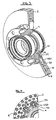
Fig. 1 teilweise geschnittene Drauf- und Seitenansichten sowie eine teilweise geschnittene perspektivische Ansicht einer ersten bevorzugten beispielhaften Ausführungsform der erfindungsgemäßen Bremsscheibenanordnung; -
Fig. 2 teilweise geschnittene Drauf- und Seitenansichten sowie eine teilweise geschnittene perspektivische Ansicht einer zweiten bevorzugten beispielhaften Ausführungsform der erfindungsgemäßen Bremsscheibenanordnung; -
Fig. 3 eine geschnittene perspektivische Ansicht einer dritten bevorzugten, beispielhaften Ausführungsform der erfindungsgemäßen Bremsscheibenanordnung; -
Fig. 4 eine geschnittene Seitenansicht einer vierten bevorzugten Ausführungsform der erfindungsgemäßen Bremsscheibenanordnung; -
Fig. 5 eine teilweise geschnittene Seitenansicht einer fünften bevorzugten Ausführungsform der erfindungsgemäßen Bremsscheibenanordnung; -
Fig. 6 eine geschnittene Seitenansicht einer sechsten bevorzugten Ausführungsform der erfindungsgemäßen Bremsscheibenanordnung; -
Figur 7 eine geschnittene Seitenansicht einer weiteren bevorzugten Ausführungsform der erfindungsgemäßen Bremsscheibenanordnung; -
Figur 8 -
Fig. 9 verschiedene Draufsichten und Querschnittsansichten von beispielhaften Ausführungsformen des erfindungsgemäßen Verbindungselements.
-
Fig. 1 partially sectioned top and side views and a partially sectioned perspective view of a first preferred exemplary embodiment of the brake disc assembly according to the invention; -
Fig. 2 partially sectioned top and side views and a partially sectioned perspective view of a second preferred exemplary embodiment of the brake disc assembly according to the invention; -
Fig. 3 a sectional perspective view of a third preferred exemplary embodiment of the brake disc assembly according to the invention; -
Fig. 4 a sectional side view of a fourth preferred embodiment of the brake disc assembly according to the invention; -
Fig. 5 a partially sectioned side view of a fifth preferred embodiment of the brake disc assembly according to the invention; -
Fig. 6 a sectional side view of a sixth preferred embodiment of the brake disc assembly according to the invention; -
FIG. 7 a sectional side view of another preferred embodiment of the brake disc assembly according to the invention; -
FIG. 8 a sectional side view of another preferred embodiment of the brake disc assembly according to the invention; -
Fig. 9 various plan views and cross-sectional views of exemplary embodiments of the connecting element according to the invention.
Die in
Der Reibring 2 ist in der dargestellten Ausführungsform als innenbelüfteter Reibring ausgebildet und besteht somit aus zwei ringförmigen Scheiben, welche über eine Vielzahl von Stegen 8 derart miteinander verbunden sind, dass ein Zirkulationsraum 10 entsteht. Es versteht sich, dass der Reibring 2 ebenfalls als massiver Körper ohne Zirkulationsraum ausgebildet sein kann.The
Zur Aufnahme des Verbindungselements 6 weist der Reibring 2 einen Aufnahmebereich 12 auf. Der Aufnahmebereich 12 erstreckt sich von dem Innenumfang U des Reibrings in radialer Richtung Y der Bremsscheibenanordnung in den Reibring 2 hinein.For receiving the connecting
Der Anbindungsadapter 4 ist ringförmig dargestellt und kann integraler Bestandteil einer Radnabe sein. Der Anbindungsadapter 4 dient jedoch zumindest zur mittelbaren oder unmittelbaren Anbindung der Bremsscheibenanordnung an die Radnabe oder das Rad. Zur Befestigung des Verbindungselements 6 in dem Anbindungsadapter 4 weist dieser einen Befestigungsbereich 14 auf. Der Befestigungsbereich 14 erstreckt sich vom Außenumfang V des Anbindungsadapters 4 in radialer Richtung Y in diesen hinein.The
Reibring und Anbindungsadapter sind mittels eines Gießverfahrens hergestellt, beispielsweise aus Grauguss. Besonders vorteilhafterweise bestehen Reibring 2 und Anbindungsadapter 4 aus dem gleichen Material.Friction ring and connection adapters are produced by means of a casting process, for example, gray cast iron. Particularly advantageously,
In der dargestellten Ausführungsform ist eine Vielzahl von Verbindungselementen 6 vorgesehen. Die Verbindungselemente 6 dienen zur Verbindung von Reibring 2 und Anbindungsadapter 4. Hierfür sind die Verbindungselemente 6 in dem Anbindungsadapter 4 derart ortsfest befestigt, dass diese in Bezug auf den Anbindungsadapter 4 zumindest in radialer Richtung Y nicht beweglich sind. Insbesondere ist ein erstes Ende 16 des Verbindungselements 6 starr in dem Anbindungsadapter 4 eingebettet. Das gegenüberliegende bzw. entgegengesetzte zweite Ende 18 des Verbindungselements 6 ist derart in dem Aufnahmebereich 12 des Reibrings 2 aufgenommen, dass der Reibring 2 auf dem bzw. in Bezug auf das Verbindungselement 6 radial beweglich ist. Infolgedessen kann sich der Reibring 2 während des Bremsens aufgrund der hohen Temperatur ungehindert ausdehnen, da er auf den Verbindungselementen 6 frei radial beweglich gelagert ist.In the illustrated embodiment, a plurality of connecting
Dies wird aufgrund der verschiedenen Ausdehnungskoeffizienten von Reibring 2, Anbindungsadapter 4 und Verbindungselement 6 zusätzlich begünstigt. So weist der Reibring 2 während des Bremsens die höchste Temperatur T1 auf, gefolgt von der Temperatur T2 des Verbindungselements 6, und wiederum gefolgt von der Temperatur T3 des Anbindungsadapters 4, welche kleiner als die Temperaturen T1 und T2 ist. Infolgedessen dehnt sich der Reibring 2 während des Bremsens am meisten aus, so dass ein kleiner Spalt zwischen dem Verbindungselement 6 und dem Reibring 2 entsteht. Da das Verbindungselement 6 jedoch eine höhere Temperatur T2 als der Anbindungsadapter 4 aufweist, dehnt sich dieses im Verhältnis zum Anbindungsadapter 4 stärker aus, so dass ein Presssitz zwischen dem ersten Ende 16 des Verbindungselements 6 und dem Befestigungsbereich 14 des Anbindungsadapters 4 geschaffen wird.This is additionally favored due to the different expansion coefficients of
In
In dem Befestigungsbereich 14 sind Verbindungselemente 60 vorgesehen, die als Hohlkörper mit einem sich in radialer Richtung Y erstreckenden Hohlraum 22 ausgebildet sind. Am zweiten Ende 18 des Verbindungselements 60 endet der Hohlraum 22 derart in dem Aufnahmebereich 12 des Reibrings, dass er mit dem Zirkulationsraum 10 in Verbindung steht. Hierdurch wird ermöglicht, dass Luft zwischen dem Nabeninneren durch die Ausnehmung 20 und den Hohlraum 22 in den Zirkulationsraum 10 strömen kann, wodurch die Betriebssicherheit aufgrund des optimierten Wärmehaushalts der Bremsscheibenanordnung nochmals verbessert werden kann.In the
In
In
In
In
Der Bodenabschnitt 32 des Verbindungselements 6, 60, 160, 260 kann derart vorgesehen sein, dass diese in(radialer) Höhe bzw. Abschnitt des zwischen dem Reibring 2 und Anbindungsadapter 4 ausgebildeten Spalts vorgesehen bzw. angeordnet ist. Besonders vorteilhafterweise ragt der Bodenabschnitt noch etwas (in radialer Richtung) in die jeweiligen Randbereiche des Reibrings 2 und Anbindungsadapters 4 hinein, so dass ein Verbindungselement geschaffen wird, welches besonders sicher gegen Abscherung ausgebildet ist.The
In
In
In
In einer alternativen Ausführungsform kann das Verbindungselement 6, 60 sich zu seinem zweiten Ende 18 hin verjüngend ausgebildet sein, wobei die eingangs erwähnten Querschnittskonfigurationen ebenfalls möglich sind. Schließlich können die verschiedensten Varianten miteinander kombiniert werden, so dass beispielsweise ein Verbindungselement vorgesehen werden kann, dessen beiden Ende 16, 18 sich verjüngend ausgebildet sind.In an alternative embodiment, the connecting
- 22
- Reibringfriction ring
- 44
- Anbindungsadapterconnection adapter
- 66
- Verbindungselementconnecting element
- 88th
- Stegweb
- 1010
- Zirkulationsraumcirculation space
- 1212
- Aufnahmebereichreception area
- 1414
- Befestigungsbereichfastening area
- 1616
- erstes Endefirst end
- 1818
- zweites Endesecond end
- 2020
- Ausnehmungrecess
- 2222
- Hohlraumcavity
- 3030
- erster Rücksprungfirst return
- 3232
- Bodenabschnittbottom section
- 3434
- DurchgangsöffnungThrough opening
- 3636
- zweiter Rücksprungsecond return
- 6060
- Verbindungselementconnecting element
- 160160
- Verbindungselementconnecting element
- 260260
- Verbindungselementconnecting element
- UU
- Innenumfanginner circumference
- VV
- Außenumfangouter periphery
- WW
- Innenumfanginner circumference
- XX
- Rotationsachseaxis of rotation
- YY
- radiale Richtungradial direction
- ZZ
- Längsachselongitudinal axis
Claims (13)
- Brake disc arrangement for disc brakes, in particular for land vehicles, comprising
a friction ring (2),
an attachment adapter (4) for attaching the brake disc arrangement to a wheel hub, and
at least one connection element (6; 60) for connecting the friction ring (2) and the attachment adapter (4),
wherein the attachment adapter (4) comprises a fastening area (14) in which the connection element (6; 60; 160; 260) is stationarily fixed,
wherein the friction ring (2) comprises a receptacle area (12) in which the connection element (6; 60) is accommodated such that the friction ring (2) is radially movable relative to the connection element (6; 60),
characterized in that
the connection element (160; 260) comprises at least one recess (30; 36) extending in the direction of the longitudinal axis (Z) thereof, which recess ends in a bottom section (32) of the connection element (160; 260). - Brake disc arrangement according to claim 1, wherein the friction ring (2) and the attachment adapter (4) are arranged essentially concentrically to one another around the axis of rotation of the brake disc arrangement and
wherein the receptacle area (12) of the friction ring (2) and the fastening area (14) of the attachment adapter (4) are arranged essentially in a plane perpendicular to the axis of rotation (X) of the brake disc arrangement. - Brake disc arrangement according to any one of the preceding claims, wherein the connection element (6; 60; 160; 260) is designed as an elongate body, the longitudinal axis (Z) of which is perpendicular to the axis of rotation (X) of the brake disc arrangement.
- Brake disc arrangement according to any one of the preceding claims, wherein the connection element (6; 60) is designed at least partially as a cylindrical body.
- Brake disc arrangement according to any one of the preceding claims, wherein the connection element (6; 60; 160; 260) at least partially is designed as a body tapering towards the friction ring (2).
- Brake disc arrangement according to any one of the preceding claims, wherein the connection element (60; 160; 260) is designed as a hollow body.
- Brake disc arrangement according to any one of the preceding claims, wherein the connection element (160; 260) is arranged such that the recess (30; 36) opens towards the friction ring (2) or the attachment adapter (4).
- Brake disc arrangement according to any one of the preceding claims, wherein the connection element (160; 260) comprises two recesses (30; 36) which project into the connection element (160; 260) from its two opposite end faces.
- Brake disc arrangement according to any one of the preceding claims, wherein the bottom section (32) is provided in that area of the connection element (160; 260) which corresponds to the gap existing between the friction ring (2) and the attachment adapter (4), and wherein the bottom section (32) - in the radial direction of the brake disc arrangement - preferably at least partially overlaps with the respective edge regions of the friction ring (2) and the attachment adapter (4).
- Brake disc arrangement according to any one of the preceding claims, wherein the attachment adapter (4) comprises a radial opening (20), which extends from the inner circumference (W) of the attachment adapter (4) to its fastening area (14), in which the connection element (6; 60; 160; 260) is fastened.
- Brake disc arrangement according to any one of the preceding claims, wherein the friction ring (2) is designed as an internally ventilated friction ring, and wherein the hollow space (22) of the connection element (60; 160; 260), which is formed as a hollow body, communicates with the circulation space (10) of the friction ring (2).
- Brake disc arrangement according to any one of the preceding claims, wherein the connection element (6; 60; 160; 260) comprises an anchoring area which is provided with recesses or projections in order to allow for an engagement with the fastening area (14) of the attachment adapter (4).
- Method of manufacturing a brake disc arrangement for disc brakes, in particular for land vehicles, in which a friction ring (2) and an attachment adapter (4) are separated from one another by a ring gap and connected to one another by at least one connection element (6; 60; 160; 260), one end (16) of which is accommodated stationarily in a fastening area (19) of the attachment adapter (4), and the other end (18) of which is accommodated radially movable in a receptacle area (12) of the friction ring (2), comprising the following steps:- manufacturing a foundry core,- arranging the foundry core in a casting mold such that a first chamber corresponding to the friction ring (2) and a second chamber corresponding to the attachment adapter (4) is formed,- arranging at least one connection element (6; 60; 160; 260) in a room connecting both chambers, and wherein the connection element (160; 260) comprises at least one recess (30; 36) extending in the direction of the longitudinal axis (Z) thereof, which recess ends in a bottom section (32) of the connection element (160; 260), and- filling molten metal into the casting mold.
Applications Claiming Priority (2)
| Application Number | Priority Date | Filing Date | Title |
|---|---|---|---|
| DE200810044339 DE102008044339B4 (en) | 2008-12-04 | 2008-12-04 | Brake disc arrangement for disc brakes |
| PCT/EP2009/066416 WO2010063831A1 (en) | 2008-12-04 | 2009-12-04 | Brake disc arrangement for disc brakes |
Publications (2)
| Publication Number | Publication Date |
|---|---|
| EP2340377A1 EP2340377A1 (en) | 2011-07-06 |
| EP2340377B1 true EP2340377B1 (en) | 2013-02-27 |
Family
ID=41582183
Family Applications (1)
| Application Number | Title | Priority Date | Filing Date |
|---|---|---|---|
| EP09764827A Not-in-force EP2340377B1 (en) | 2008-12-04 | 2009-12-04 | Brake disc arrangement for disc brakes |
Country Status (6)
| Country | Link |
|---|---|
| US (1) | US8967339B2 (en) |
| EP (1) | EP2340377B1 (en) |
| CN (1) | CN102239345B (en) |
| BR (1) | BRPI0922704A2 (en) |
| DE (1) | DE102008044339B4 (en) |
| WO (1) | WO2010063831A1 (en) |
Families Citing this family (18)
| Publication number | Priority date | Publication date | Assignee | Title |
|---|---|---|---|---|
| DE102010024389A1 (en) * | 2010-06-19 | 2011-12-22 | Audi Ag | Connecting device between friction ring and pot of a brake disc |
| DE102011104066A1 (en) * | 2011-06-11 | 2012-03-22 | Daimler Ag | Disk brake for motor vehicle, has friction ring and wheel hub connected together in circumferential direction by safety element, which transfers torque between ring and hub, where safety element is accommodated in openings of ring and hub |
| KR20130064304A (en) * | 2011-12-08 | 2013-06-18 | 현대자동차주식회사 | Brake disk |
| DE102012205410B4 (en) * | 2012-04-03 | 2016-03-17 | Saf-Holland Gmbh | Brake disc arrangement for disc brakes |
| CN102966689B (en) * | 2012-12-27 | 2016-01-20 | 郑州精益达汽车零部件有限公司 | Automotive brake disc |
| DE102013002300B3 (en) * | 2013-02-08 | 2014-07-17 | Audi Ag | Brake disc for a disc brake of a motor vehicle |
| MX365070B (en) | 2013-07-19 | 2019-05-22 | Hendrickson Usa Llc | Improved disc brake rotor for heavy-duty vehicles. |
| US10267370B2 (en) | 2016-02-09 | 2019-04-23 | Saf-Holland, Inc. | Disc brake rotor adapter |
| US10100888B2 (en) * | 2016-05-16 | 2018-10-16 | Shimano Inc. | Bicycle disc brake rotor |
| DE102016115996A1 (en) * | 2016-08-29 | 2018-03-01 | Knorr-Bremse Systeme für Schienenfahrzeuge GmbH | Wave brake disk for a rail vehicle |
| DE102016122321B4 (en) | 2016-11-21 | 2019-04-25 | Shw Automotive Gmbh | brake disc |
| IT201700107187A1 (en) * | 2017-09-25 | 2019-03-25 | Freni Brembo Spa | BRAKING DEVICE |
| US10830295B2 (en) | 2018-07-20 | 2020-11-10 | Bendix Spicer Foundation Brake Llc | Brake disc mounting arrangement |
| US10704628B2 (en) | 2018-07-20 | 2020-07-07 | Bendix Spicer Foundation Brake Llc | Brake disc mounting arrangement |
| US10837509B2 (en) | 2018-07-20 | 2020-11-17 | Bendix Spicer Foundation Brake Llc | Brake disc mounting arrangement |
| PL3712459T3 (en) * | 2019-02-08 | 2021-12-06 | SHW Brake Systems GmbH | Brake disc |
| JP7267051B2 (en) * | 2019-03-22 | 2023-05-01 | サンスター技研株式会社 | brake disc |
| US20230012996A1 (en) * | 2021-07-19 | 2023-01-19 | Poli S.R.L. | Brake system and method |
Family Cites Families (18)
| Publication number | Priority date | Publication date | Assignee | Title |
|---|---|---|---|---|
| CH407673A (en) | 1962-02-14 | 1966-02-15 | Knorr Bremse Gmbh | Brake disc for disc brakes |
| DE2510640A1 (en) | 1975-03-12 | 1976-09-23 | Knorr Bremse Gmbh | BRAKE DISC FOR DISC BRAKES OF RAIL VEHICLES |
| EP0198217A1 (en) | 1985-04-18 | 1986-10-22 | Allied Corporation | Disc brake rotor |
| DE69409988T2 (en) * | 1993-02-10 | 1998-12-17 | Yutaka Giken Co Ltd | Floating brake disc |
| DE4437331C2 (en) * | 1994-07-26 | 1999-01-07 | Bergische Stahlindustrie | Vented split shaft brake disc |
| DE19929390B4 (en) * | 1999-06-28 | 2004-05-06 | Otto Sauer Achsenfabrik Keilberg | Brake disc arrangement |
| ES2161678T3 (en) * | 2000-03-09 | 2001-12-16 | Freni Brembo Spa | VENTILATED DISC FOR A DISC BRAKE. |
| DE10103639B4 (en) | 2001-01-27 | 2004-07-29 | Audi Ag | Ventilated brake disc |
| DE10142806B4 (en) * | 2001-08-31 | 2005-02-10 | Audi Ag | brake disc |
| DE10322454A1 (en) | 2002-06-12 | 2004-02-26 | Continental Teves Ag & Co. Ohg | Brake disc has friction ring which at least in region of corresponding holes for engagement of protrusions on holding section is formed from brittle material, and sleeve-form intermediate elements are fitted in holes in friction ring |
| DE10227529B4 (en) * | 2002-06-20 | 2010-04-01 | Daimler Ag | Method for producing a brake disk and brake disk |
| DE102004008958B4 (en) * | 2004-02-24 | 2017-08-31 | Volkswagen Ag | Method for producing a brake disk, brake disk and connecting element |
| JP4424259B2 (en) * | 2005-06-06 | 2010-03-03 | 日産自動車株式会社 | 2 piece rotor |
| DE102006043945A1 (en) * | 2006-09-14 | 2008-03-27 | Schwäbische Hüttenwerke Automotive GmbH & Co. KG | Ventilated brake disc |
| DE102007001211B4 (en) * | 2007-01-05 | 2009-06-10 | Knorr-Bremse Systeme für Nutzfahrzeuge GmbH | Brake disk / hub connection |
| DE102007013512A1 (en) | 2007-03-21 | 2008-09-25 | Audi Ag | Brake disc for a disc brake of a vehicle and method for producing such a brake disc |
| DE102008042173A1 (en) * | 2008-09-17 | 2010-03-18 | Robert Bosch Gmbh | brake disc |
| JP2010106916A (en) * | 2008-10-29 | 2010-05-13 | Advics Co Ltd | Disk rotor |
-
2008
- 2008-12-04 DE DE200810044339 patent/DE102008044339B4/en active Active
-
2009
- 2009-12-04 BR BRPI0922704A patent/BRPI0922704A2/en not_active IP Right Cessation
- 2009-12-04 WO PCT/EP2009/066416 patent/WO2010063831A1/en active Application Filing
- 2009-12-04 EP EP09764827A patent/EP2340377B1/en not_active Not-in-force
- 2009-12-04 CN CN200980145311.4A patent/CN102239345B/en not_active Expired - Fee Related
- 2009-12-04 US US13/130,695 patent/US8967339B2/en not_active Expired - Fee Related
Also Published As
| Publication number | Publication date |
|---|---|
| DE102008044339B4 (en) | 2012-01-26 |
| CN102239345B (en) | 2015-02-04 |
| CN102239345A (en) | 2011-11-09 |
| EP2340377A1 (en) | 2011-07-06 |
| US8967339B2 (en) | 2015-03-03 |
| BRPI0922704A2 (en) | 2016-01-05 |
| WO2010063831A1 (en) | 2010-06-10 |
| DE102008044339A1 (en) | 2010-06-10 |
| US20110278115A1 (en) | 2011-11-17 |
Similar Documents
| Publication | Publication Date | Title |
|---|---|---|
| EP2340377B1 (en) | Brake disc arrangement for disc brakes | |
| EP0403799B1 (en) | Brake disc for disc brakes | |
| DE19649919C2 (en) | Brake members made of composite casting, namely brake drum, brake disc or the like, and composite casting method for the production of brake members | |
| EP3033540B1 (en) | Brake disc for a vehicle | |
| EP2834533B1 (en) | Brake disc arrangement for disc brakes | |
| EP1972823B1 (en) | Brake disc for a disc brake of a vehicle and method for manufacturing such a brake disk | |
| EP3712459B1 (en) | Brake disc | |
| EP2553290B1 (en) | Brake disc | |
| DE4430957A1 (en) | Brake caliper for disc brake | |
| EP1802411A1 (en) | Casting die and method for producing cast workpieces consisting of light metal alloys | |
| DE19807184C1 (en) | Brake disk for commercial vehicle | |
| DE102009013358A1 (en) | Brake disk for vehicle, has friction ring with opening, and pot molded at friction ring, where friction ring is provided with two ring elements with front ends connected with each other by bar that is projected into opening | |
| EP2100051B1 (en) | Brake disk for a disk brake | |
| DE102016202543A1 (en) | Method for producing a brake caliper of a vehicle | |
| EP0241767B1 (en) | Disc brake device | |
| EP3844416B1 (en) | Brake disc for a disc brake | |
| EP3170678B1 (en) | Wheel hub | |
| DE102016103396B4 (en) | Disc brake pad and brake pad set | |
| EP3449148B1 (en) | Brake disc for a vehicle | |
| EP2519756B1 (en) | Brake calliper for a vehicle brake system and method and device for producing a brake calliper | |
| EP1903248A1 (en) | Brake disc | |
| WO2020156920A1 (en) | Method for producing a cast vehicle wheel | |
| WO2020035618A1 (en) | Assembled brake disc, and method for producing a brake disc of this type | |
| DE3536465C2 (en) | ||
| AT510752A1 (en) | BRAKE DISC DEVICE |
Legal Events
| Date | Code | Title | Description |
|---|---|---|---|
| PUAI | Public reference made under article 153(3) epc to a published international application that has entered the european phase |
Free format text: ORIGINAL CODE: 0009012 |
|
| 17P | Request for examination filed |
Effective date: 20110408 |
|
| AK | Designated contracting states |
Kind code of ref document: A1 Designated state(s): AT BE BG CH CY CZ DE DK EE ES FI FR GB GR HR HU IE IS IT LI LT LU LV MC MK MT NL NO PL PT RO SE SI SK SM TR |
|
| AX | Request for extension of the european patent |
Extension state: AL BA RS |
|
| DAX | Request for extension of the european patent (deleted) | ||
| 17Q | First examination report despatched |
Effective date: 20120319 |
|
| GRAP | Despatch of communication of intention to grant a patent |
Free format text: ORIGINAL CODE: EPIDOSNIGR1 |
|
| GRAS | Grant fee paid |
Free format text: ORIGINAL CODE: EPIDOSNIGR3 |
|
| GRAA | (expected) grant |
Free format text: ORIGINAL CODE: 0009210 |
|
| AK | Designated contracting states |
Kind code of ref document: B1 Designated state(s): AT BE BG CH CY CZ DE DK EE ES FI FR GB GR HR HU IE IS IT LI LT LU LV MC MK MT NL NO PL PT RO SE SI SK SM TR |
|
| REG | Reference to a national code |
Ref country code: GB Ref legal event code: FG4D Free format text: NOT ENGLISH |
|
| REG | Reference to a national code |
Ref country code: CH Ref legal event code: EP |
|
| REG | Reference to a national code |
Ref country code: AT Ref legal event code: REF Ref document number: 598682 Country of ref document: AT Kind code of ref document: T Effective date: 20130315 |
|
| REG | Reference to a national code |
Ref country code: IE Ref legal event code: FG4D Free format text: LANGUAGE OF EP DOCUMENT: GERMAN |
|
| REG | Reference to a national code |
Ref country code: DE Ref legal event code: R096 Ref document number: 502009006390 Country of ref document: DE Effective date: 20130425 |
|
| REG | Reference to a national code |
Ref country code: NL Ref legal event code: T3 |
|
| REG | Reference to a national code |
Ref country code: SE Ref legal event code: TRGR |
|
| REG | Reference to a national code |
Ref country code: LT Ref legal event code: MG4D |
|
| PG25 | Lapsed in a contracting state [announced via postgrant information from national office to epo] |
Ref country code: LT Free format text: LAPSE BECAUSE OF FAILURE TO SUBMIT A TRANSLATION OF THE DESCRIPTION OR TO PAY THE FEE WITHIN THE PRESCRIBED TIME-LIMIT Effective date: 20130227 Ref country code: BG Free format text: LAPSE BECAUSE OF FAILURE TO SUBMIT A TRANSLATION OF THE DESCRIPTION OR TO PAY THE FEE WITHIN THE PRESCRIBED TIME-LIMIT Effective date: 20130527 Ref country code: NO Free format text: LAPSE BECAUSE OF FAILURE TO SUBMIT A TRANSLATION OF THE DESCRIPTION OR TO PAY THE FEE WITHIN THE PRESCRIBED TIME-LIMIT Effective date: 20130527 Ref country code: ES Free format text: LAPSE BECAUSE OF FAILURE TO SUBMIT A TRANSLATION OF THE DESCRIPTION OR TO PAY THE FEE WITHIN THE PRESCRIBED TIME-LIMIT Effective date: 20130607 Ref country code: IS Free format text: LAPSE BECAUSE OF FAILURE TO SUBMIT A TRANSLATION OF THE DESCRIPTION OR TO PAY THE FEE WITHIN THE PRESCRIBED TIME-LIMIT Effective date: 20130627 |
|
| PG25 | Lapsed in a contracting state [announced via postgrant information from national office to epo] |
Ref country code: LV Free format text: LAPSE BECAUSE OF FAILURE TO SUBMIT A TRANSLATION OF THE DESCRIPTION OR TO PAY THE FEE WITHIN THE PRESCRIBED TIME-LIMIT Effective date: 20130227 Ref country code: SI Free format text: LAPSE BECAUSE OF FAILURE TO SUBMIT A TRANSLATION OF THE DESCRIPTION OR TO PAY THE FEE WITHIN THE PRESCRIBED TIME-LIMIT Effective date: 20130227 Ref country code: PT Free format text: LAPSE BECAUSE OF FAILURE TO SUBMIT A TRANSLATION OF THE DESCRIPTION OR TO PAY THE FEE WITHIN THE PRESCRIBED TIME-LIMIT Effective date: 20130627 Ref country code: GR Free format text: LAPSE BECAUSE OF FAILURE TO SUBMIT A TRANSLATION OF THE DESCRIPTION OR TO PAY THE FEE WITHIN THE PRESCRIBED TIME-LIMIT Effective date: 20130528 Ref country code: PL Free format text: LAPSE BECAUSE OF FAILURE TO SUBMIT A TRANSLATION OF THE DESCRIPTION OR TO PAY THE FEE WITHIN THE PRESCRIBED TIME-LIMIT Effective date: 20130227 Ref country code: FI Free format text: LAPSE BECAUSE OF FAILURE TO SUBMIT A TRANSLATION OF THE DESCRIPTION OR TO PAY THE FEE WITHIN THE PRESCRIBED TIME-LIMIT Effective date: 20130227 |
|
| PG25 | Lapsed in a contracting state [announced via postgrant information from national office to epo] |
Ref country code: HR Free format text: LAPSE BECAUSE OF FAILURE TO SUBMIT A TRANSLATION OF THE DESCRIPTION OR TO PAY THE FEE WITHIN THE PRESCRIBED TIME-LIMIT Effective date: 20130227 |
|
| PG25 | Lapsed in a contracting state [announced via postgrant information from national office to epo] |
Ref country code: EE Free format text: LAPSE BECAUSE OF FAILURE TO SUBMIT A TRANSLATION OF THE DESCRIPTION OR TO PAY THE FEE WITHIN THE PRESCRIBED TIME-LIMIT Effective date: 20130227 Ref country code: RO Free format text: LAPSE BECAUSE OF FAILURE TO SUBMIT A TRANSLATION OF THE DESCRIPTION OR TO PAY THE FEE WITHIN THE PRESCRIBED TIME-LIMIT Effective date: 20130227 Ref country code: SK Free format text: LAPSE BECAUSE OF FAILURE TO SUBMIT A TRANSLATION OF THE DESCRIPTION OR TO PAY THE FEE WITHIN THE PRESCRIBED TIME-LIMIT Effective date: 20130227 Ref country code: DK Free format text: LAPSE BECAUSE OF FAILURE TO SUBMIT A TRANSLATION OF THE DESCRIPTION OR TO PAY THE FEE WITHIN THE PRESCRIBED TIME-LIMIT Effective date: 20130227 Ref country code: CZ Free format text: LAPSE BECAUSE OF FAILURE TO SUBMIT A TRANSLATION OF THE DESCRIPTION OR TO PAY THE FEE WITHIN THE PRESCRIBED TIME-LIMIT Effective date: 20130227 |
|
| PG25 | Lapsed in a contracting state [announced via postgrant information from national office to epo] |
Ref country code: CY Free format text: LAPSE BECAUSE OF FAILURE TO SUBMIT A TRANSLATION OF THE DESCRIPTION OR TO PAY THE FEE WITHIN THE PRESCRIBED TIME-LIMIT Effective date: 20130227 |
|
| PG25 | Lapsed in a contracting state [announced via postgrant information from national office to epo] |
Ref country code: IT Free format text: LAPSE BECAUSE OF FAILURE TO SUBMIT A TRANSLATION OF THE DESCRIPTION OR TO PAY THE FEE WITHIN THE PRESCRIBED TIME-LIMIT Effective date: 20130227 |
|
| PLBE | No opposition filed within time limit |
Free format text: ORIGINAL CODE: 0009261 |
|
| STAA | Information on the status of an ep patent application or granted ep patent |
Free format text: STATUS: NO OPPOSITION FILED WITHIN TIME LIMIT |
|
| 26N | No opposition filed |
Effective date: 20131128 |
|
| REG | Reference to a national code |
Ref country code: DE Ref legal event code: R097 Ref document number: 502009006390 Country of ref document: DE Effective date: 20131128 |
|
| BERE | Be: lapsed |
Owner name: SAF-HOLLAND G.M.B.H. Effective date: 20131231 |
|
| REG | Reference to a national code |
Ref country code: SE Ref legal event code: EUG |
|
| REG | Reference to a national code |
Ref country code: CH Ref legal event code: PL |
|
| PG25 | Lapsed in a contracting state [announced via postgrant information from national office to epo] |
Ref country code: MC Free format text: LAPSE BECAUSE OF FAILURE TO SUBMIT A TRANSLATION OF THE DESCRIPTION OR TO PAY THE FEE WITHIN THE PRESCRIBED TIME-LIMIT Effective date: 20130227 Ref country code: SE Free format text: LAPSE BECAUSE OF NON-PAYMENT OF DUE FEES Effective date: 20131205 Ref country code: LU Free format text: LAPSE BECAUSE OF FAILURE TO SUBMIT A TRANSLATION OF THE DESCRIPTION OR TO PAY THE FEE WITHIN THE PRESCRIBED TIME-LIMIT Effective date: 20131204 |
|
| REG | Reference to a national code |
Ref country code: IE Ref legal event code: MM4A |
|
| PG25 | Lapsed in a contracting state [announced via postgrant information from national office to epo] |
Ref country code: LI Free format text: LAPSE BECAUSE OF NON-PAYMENT OF DUE FEES Effective date: 20131231 Ref country code: CH Free format text: LAPSE BECAUSE OF NON-PAYMENT OF DUE FEES Effective date: 20131231 Ref country code: IE Free format text: LAPSE BECAUSE OF NON-PAYMENT OF DUE FEES Effective date: 20131204 Ref country code: BE Free format text: LAPSE BECAUSE OF NON-PAYMENT OF DUE FEES Effective date: 20131231 |
|
| PG25 | Lapsed in a contracting state [announced via postgrant information from national office to epo] |
Ref country code: SM Free format text: LAPSE BECAUSE OF FAILURE TO SUBMIT A TRANSLATION OF THE DESCRIPTION OR TO PAY THE FEE WITHIN THE PRESCRIBED TIME-LIMIT Effective date: 20130227 |
|
| PG25 | Lapsed in a contracting state [announced via postgrant information from national office to epo] |
Ref country code: HU Free format text: LAPSE BECAUSE OF FAILURE TO SUBMIT A TRANSLATION OF THE DESCRIPTION OR TO PAY THE FEE WITHIN THE PRESCRIBED TIME-LIMIT; INVALID AB INITIO Effective date: 20091204 Ref country code: MK Free format text: LAPSE BECAUSE OF FAILURE TO SUBMIT A TRANSLATION OF THE DESCRIPTION OR TO PAY THE FEE WITHIN THE PRESCRIBED TIME-LIMIT Effective date: 20130227 |
|
| PG25 | Lapsed in a contracting state [announced via postgrant information from national office to epo] |
Ref country code: MT Free format text: LAPSE BECAUSE OF FAILURE TO SUBMIT A TRANSLATION OF THE DESCRIPTION OR TO PAY THE FEE WITHIN THE PRESCRIBED TIME-LIMIT Effective date: 20130227 |
|
| REG | Reference to a national code |
Ref country code: FR Ref legal event code: PLFP Year of fee payment: 7 |
|
| REG | Reference to a national code |
Ref country code: AT Ref legal event code: MM01 Ref document number: 598682 Country of ref document: AT Kind code of ref document: T Effective date: 20141204 |
|
| PG25 | Lapsed in a contracting state [announced via postgrant information from national office to epo] |
Ref country code: AT Free format text: LAPSE BECAUSE OF NON-PAYMENT OF DUE FEES Effective date: 20141204 |
|
| REG | Reference to a national code |
Ref country code: FR Ref legal event code: PLFP Year of fee payment: 8 |
|
| REG | Reference to a national code |
Ref country code: FR Ref legal event code: PLFP Year of fee payment: 9 |
|
| PGFP | Annual fee paid to national office [announced via postgrant information from national office to epo] |
Ref country code: NL Payment date: 20181217 Year of fee payment: 10 |
|
| PGFP | Annual fee paid to national office [announced via postgrant information from national office to epo] |
Ref country code: DE Payment date: 20191018 Year of fee payment: 11 |
|
| PGFP | Annual fee paid to national office [announced via postgrant information from national office to epo] |
Ref country code: FR Payment date: 20191218 Year of fee payment: 11 |
|
| PGFP | Annual fee paid to national office [announced via postgrant information from national office to epo] |
Ref country code: TR Payment date: 20191129 Year of fee payment: 11 |
|
| PGFP | Annual fee paid to national office [announced via postgrant information from national office to epo] |
Ref country code: GB Payment date: 20191220 Year of fee payment: 11 |
|
| REG | Reference to a national code |
Ref country code: NL Ref legal event code: MM Effective date: 20200101 |
|
| PG25 | Lapsed in a contracting state [announced via postgrant information from national office to epo] |
Ref country code: NL Free format text: LAPSE BECAUSE OF NON-PAYMENT OF DUE FEES Effective date: 20200101 |
|
| REG | Reference to a national code |
Ref country code: DE Ref legal event code: R119 Ref document number: 502009006390 Country of ref document: DE |
|
| GBPC | Gb: european patent ceased through non-payment of renewal fee |
Effective date: 20201204 |
|
| PG25 | Lapsed in a contracting state [announced via postgrant information from national office to epo] |
Ref country code: FR Free format text: LAPSE BECAUSE OF NON-PAYMENT OF DUE FEES Effective date: 20201231 |
|
| PG25 | Lapsed in a contracting state [announced via postgrant information from national office to epo] |
Ref country code: GB Free format text: LAPSE BECAUSE OF NON-PAYMENT OF DUE FEES Effective date: 20201204 Ref country code: DE Free format text: LAPSE BECAUSE OF NON-PAYMENT OF DUE FEES Effective date: 20210701 |
|
| PG25 | Lapsed in a contracting state [announced via postgrant information from national office to epo] |
Ref country code: TR Free format text: LAPSE BECAUSE OF NON-PAYMENT OF DUE FEES Effective date: 20201204 |