EP3033540B1 - Brake disc for a vehicle - Google Patents
Brake disc for a vehicle Download PDFInfo
- Publication number
- EP3033540B1 EP3033540B1 EP14738528.0A EP14738528A EP3033540B1 EP 3033540 B1 EP3033540 B1 EP 3033540B1 EP 14738528 A EP14738528 A EP 14738528A EP 3033540 B1 EP3033540 B1 EP 3033540B1
- Authority
- EP
- European Patent Office
- Prior art keywords
- brake disc
- friction ring
- hat
- rivets
- brake
- Prior art date
- Legal status (The legal status is an assumption and is not a legal conclusion. Google has not performed a legal analysis and makes no representation as to the accuracy of the status listed.)
- Active
Links
- 229910000831 Steel Inorganic materials 0.000 claims description 22
- 239000010959 steel Substances 0.000 claims description 22
- 239000000463 material Substances 0.000 claims description 14
- 238000000034 method Methods 0.000 claims description 6
- 229910000639 Spring steel Inorganic materials 0.000 claims description 5
- 229910052751 metal Inorganic materials 0.000 claims description 4
- 239000002184 metal Substances 0.000 claims description 4
- 238000004519 manufacturing process Methods 0.000 claims description 3
- 239000007769 metal material Substances 0.000 claims description 3
- 229910001060 Gray iron Inorganic materials 0.000 description 5
- 229910052782 aluminium Inorganic materials 0.000 description 2
- XAGFODPZIPBFFR-UHFFFAOYSA-N aluminium Chemical compound [Al] XAGFODPZIPBFFR-UHFFFAOYSA-N 0.000 description 2
- 239000002131 composite material Substances 0.000 description 2
- 238000009826 distribution Methods 0.000 description 2
- 238000009434 installation Methods 0.000 description 2
- 238000005304 joining Methods 0.000 description 2
- 238000003754 machining Methods 0.000 description 2
- 230000036316 preload Effects 0.000 description 2
- CWYNVVGOOAEACU-UHFFFAOYSA-N Fe2+ Chemical compound [Fe+2] CWYNVVGOOAEACU-UHFFFAOYSA-N 0.000 description 1
- FYYHWMGAXLPEAU-UHFFFAOYSA-N Magnesium Chemical compound [Mg] FYYHWMGAXLPEAU-UHFFFAOYSA-N 0.000 description 1
- 238000005266 casting Methods 0.000 description 1
- 238000010276 construction Methods 0.000 description 1
- 238000001816 cooling Methods 0.000 description 1
- 238000005260 corrosion Methods 0.000 description 1
- 230000007797 corrosion Effects 0.000 description 1
- 230000001419 dependent effect Effects 0.000 description 1
- 238000005553 drilling Methods 0.000 description 1
- 238000001125 extrusion Methods 0.000 description 1
- 230000002349 favourable effect Effects 0.000 description 1
- 238000005242 forging Methods 0.000 description 1
- 239000003562 lightweight material Substances 0.000 description 1
- 229910052749 magnesium Inorganic materials 0.000 description 1
- 239000011777 magnesium Substances 0.000 description 1
- -1 magnesium) Chemical class 0.000 description 1
- 150000002739 metals Chemical class 0.000 description 1
- 229910052755 nonmetal Inorganic materials 0.000 description 1
- 230000000284 resting effect Effects 0.000 description 1
- 238000003466 welding Methods 0.000 description 1
Images


Classifications
-
- F—MECHANICAL ENGINEERING; LIGHTING; HEATING; WEAPONS; BLASTING
- F16—ENGINEERING ELEMENTS AND UNITS; GENERAL MEASURES FOR PRODUCING AND MAINTAINING EFFECTIVE FUNCTIONING OF MACHINES OR INSTALLATIONS; THERMAL INSULATION IN GENERAL
- F16D—COUPLINGS FOR TRANSMITTING ROTATION; CLUTCHES; BRAKES
- F16D65/00—Parts or details
- F16D65/02—Braking members; Mounting thereof
- F16D65/12—Discs; Drums for disc brakes
- F16D65/123—Discs; Drums for disc brakes comprising an annular disc secured to a hub member; Discs characterised by means for mounting
-
- F—MECHANICAL ENGINEERING; LIGHTING; HEATING; WEAPONS; BLASTING
- F16—ENGINEERING ELEMENTS AND UNITS; GENERAL MEASURES FOR PRODUCING AND MAINTAINING EFFECTIVE FUNCTIONING OF MACHINES OR INSTALLATIONS; THERMAL INSULATION IN GENERAL
- F16D—COUPLINGS FOR TRANSMITTING ROTATION; CLUTCHES; BRAKES
- F16D65/00—Parts or details
- F16D65/02—Braking members; Mounting thereof
- F16D65/12—Discs; Drums for disc brakes
- F16D65/125—Discs; Drums for disc brakes characterised by the material used for the disc body
-
- F—MECHANICAL ENGINEERING; LIGHTING; HEATING; WEAPONS; BLASTING
- F16—ENGINEERING ELEMENTS AND UNITS; GENERAL MEASURES FOR PRODUCING AND MAINTAINING EFFECTIVE FUNCTIONING OF MACHINES OR INSTALLATIONS; THERMAL INSULATION IN GENERAL
- F16D—COUPLINGS FOR TRANSMITTING ROTATION; CLUTCHES; BRAKES
- F16D65/00—Parts or details
- F16D65/02—Braking members; Mounting thereof
- F16D65/12—Discs; Drums for disc brakes
- F16D65/127—Discs; Drums for disc brakes characterised by properties of the disc surface; Discs lined with friction material
-
- F—MECHANICAL ENGINEERING; LIGHTING; HEATING; WEAPONS; BLASTING
- F16—ENGINEERING ELEMENTS AND UNITS; GENERAL MEASURES FOR PRODUCING AND MAINTAINING EFFECTIVE FUNCTIONING OF MACHINES OR INSTALLATIONS; THERMAL INSULATION IN GENERAL
- F16D—COUPLINGS FOR TRANSMITTING ROTATION; CLUTCHES; BRAKES
- F16D65/00—Parts or details
- F16D65/02—Braking members; Mounting thereof
- F16D2065/13—Parts or details of discs or drums
- F16D2065/134—Connection
- F16D2065/1392—Connection elements
Definitions
- Brake disks are components of a brake system for motor vehicles which are mounted coaxially with a wheel and which have a friction ring and a brake disk chamber.
- the brake disk chamber is used to fasten the brake disk to a wheel hub, while the friction ring is brought into tribological contact with the brake linings of the brake system during the braking process.
- the kinetic energy of the motor vehicle is dissipated in the form of frictional heat and the vehicle is braked.
- Friction rings are therefore usually made as cast components, in particular in GG-15 or GG-25.
- Such friction rings are often designed in the form of internally ventilated friction rings, that is, they are provided with channels or bores through which air flows in order to improve the dissipation of heat from the friction ring.
- Such a brake disc in which the (usually connected) friction ring (s) are manufactured separately from the brake disc chamber and then suitably connected to it, has the advantage that the friction ring (s) on the one hand and the brake disc chamber on the other hand are made up of the most favorable for the respective requirements Materials can be made. In this way, for example, on the one hand, a weight saving can be achieved and, on the other hand, an advantageous decoupling between the friction ring and the brake disk chamber is possible.
- the EP 1 260 728 A1 describes a two-part brake disc with a screw connection, in which radial depressions are formed in a holding part at its fastening points, which form space for screw heads. These troughs stiffen the holding part, which is decoupled from the friction ring by means of a low connection preload.
- the brake disc chamber which is essentially shaped as usual, has a circular-cylindrical jacket with respect to the axis of rotation of the disc brake, in which openings or at least sections with reduced wall thickness are provided.
- This brake disc chamber has a certain elasticity that is conducive to an essentially unhindered thermal expansion of the friction ring, ie the unavoidable thermal expansion of the friction ring is not significantly hindered by the brake disc chamber, so that no stresses are built up and undesirable deformations of the friction ring are excluded.
- a higher-strength steel material or the like is proposed as the material for the brake disc chamber. This known construction requires a relatively large amount of installation space in the radial direction, which is why it can only be used with larger brake disk dimensions (diameters)
- the object of the present invention is to avoid this disadvantage, that is to say to provide a brake disc, especially for smaller motor vehicles, in which the space requirement for the connection of the brake disc to the wheel hub can be kept low by a suitable connection of the friction ring and the brake disc chamber.
- the object is achieved according to the invention with the features of claim 1. Further refinements of the invention emerge from the dependent claims.
- a brake disc for a disc brake which consists of a brake disc chamber and at least one friction ring connected to this by means of rivets, the casing of the brake disc chamber being provided with sections with reduced wall thickness and / or openings, these being located on the outer circumference of the brake disc chamber casing are axially directed material recesses that are used to / for at least partial placement of the rivets.
- the rivets can thus be pulled as close as possible to the casing of the brake disc chamber and at least partially protrude into the axially directed recesses, rivets preferably (also) extending in the axial direction, ie parallel to the axis of rotation of the brake disc. That has The advantage that the brake disc chamber, made for example from a light metal, has a friction ring in the axial direction, for example made of gray cast iron, due to the material recesses on the jacket of the brake disk chamber can be riveted in such a way that the installation space required for the rivet in the radial direction is significantly reduced.
- a connection area between the brake disk chamber and the friction ring with small or minimized dimensions in the radial direction can thus be represented so that the diameter of the brake disk chamber can be kept small and, as a result, a smaller brake disk can be represented.
- the shape of the axially aligned recesses is preferably adapted to the rivet, each recess not having to completely accommodate the associated rivet; rather, it is sufficient if the respective rivet only partially protrudes into the associated recess. This is because the recesses must not be made too large either, so that the brake disk chamber or its casing is not weakened too intensely.
- the recess can be designed for an essentially circular-cylindrical rivet, for example in the form of a "semicircular cylinder", the cylinder axis of which lies in the area of the outer side of the brake disc chamber shell, which is cylindrical, ignoring these recesses, and is parallel, just like the longitudinal axis of the rivet extends to the axis of rotation of the brake disc.
- the term "placement" used which is used by the recesses for the rivets, is not only to be understood as the final state with the rivets installed, but also the assembly process of the rivets, ie the recesses in question serve or at least can serve to be able to assemble the rivet.
- the brake disc chamber is made of light metal or steel or a non-metal material, that is, higher-strength, high-strength light metals (including magnesium), or a high-strength, thin-walled sheet steel or aluminum and other non-ferrous materials are preferably used as materials for the pot. or non-metallic materials in question.
- the brake disk chamber can therefore be produced, for example, by a casting process or a forging process or by extrusion.
- a radial steel ring is provided in the contact area between the brake disk chamber and the wheel resting against it, or if the chamber consists of a correspondingly resistant one light material is made. Said steel ring can be inserted or cast into a recess in the brake disk chamber in order to avoid a steel wheel that might otherwise be incorporated into the material of the brake disk chamber when the vehicle is in motion.
- the friction ring and the brake disk chamber can advantageously be centered with respect to one another via the rivets and / or via appropriately provided centering lugs.
- the friction ring can have at least one fastening extension directed inward from the friction surface, to which an edge or collar of the brake disk chamber shell can be connected by axially directed rivets.
- the joint between the friction ring and the brake disk chamber can advantageously be designed as a press fit or shrink fit or as an integral or form-fitting connection.
- the connection between the brake disc chamber and the friction ring is represented by a rivet connection, i.e. rivets are used.
- the wobble riveting process can be used, for example.
- Knurled and / or compressed and / or stepped rivets (with a press fit) can be used to generate the greatest possible freedom from play and thus a quasi-absolute form fit between the brake disk chamber and the friction ring or the friction disk.
- an annular steel band can be provided which is attached between the rivet locking heads and the connection surface of the friction ring. This measure advantageously results in a planar force distribution or force introduction into the friction ring via the steel strip. If elevations are incorporated into the surface of the friction ring between the individual rivet closing heads, so that the steel band, for example designed as a spring steel ring, is tensioned in a wavy manner due to these elevations or level differences, a certain preload, similar to a screw connection, can thereby be generated. Alternatively, the steel band or the spring steel ring itself can be designed in a correspondingly undulating manner.
- Such a pre-tensioning increases the stability of the riveted connection, it being possible for a comparable measure to be provided with other connecting means and contributes to the distribution of the stresses that arise during operation.
- a screw connection for the connecting means
- suitable washers made of steel or spring steel, e.g. in the form of a disc spring
- the rivet closing head or the like
- the friction ring can absorb the stresses that arise during riveting.
- the same would also be possible on the collar of the brake disc chamber.
- the brake disk chamber can have a centering (“centering shoulder”) in the form of a protruding collar, which simplifies the (pre) joining.
- the brake disc chamber can be (pre) connected to the friction ring in this centering area by means of friction welding.
- the pot is fixed to the brake disc and the (pre) joining for the manufacturing process, in which the rivets are fixed between the friction ring and the brake disc pot, as well as for a preceding, in particular machining, manufacturing step in which the said material recesses for at least partial placement the rivet can be made, for example, by drilling, is significantly simplified.
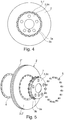
- the brake disc 1 shown in the figures consists of a brake disc chamber 3 and a friction ring 2 and is provided (as usual) for mounting on a wheel hub (not shown) in order to rotate with it about the axis of rotation D during operation.
- the one-piece internally cooled friction ring 2 made of gray cast iron consists of two friction disks 2 ', 2 "with cooling air ducts 2' '' in between and connecting them 'extends in the radial direction R (with respect to the axis of rotation D) with what is known as a fastening extension 9 by a certain (small) amount further towards the axis of rotation D than the other friction disk 2 ′′ which is further away from the brake disk chamber 3 in the axial direction.
- the brake disk chamber 3 is in the form of rivets (for this is also used with the reference number 5) connected to the friction disk 2 'and thus to the friction ring 2.
- the present speaks of a connection between the brake disk chamber 3 and the friction ring 2.
- Recesses 7, into which the rivets 5 protrude, into which the rivets 5 are at least partially placed, are made in the jacket 3a of the brake disk chamber 3 and to a small extent also in the bottom 3c of the brake disk chamber 3, evenly distributed over the circumference of the brake disk chamber 3.
- Each of these recesses 7, which are also referred to as sections 7 with reduced wall thickness and can also be designed in the form of a breakthrough, extends in the axial direction in order to at least partially not only receive, but also set, ie how visible to be able to assemble in the axial direction.
- these recesses 7 have the shape of a semicircular cylinder and are, for example, made in the jacket 3a of the brake disk chamber 3 by machining in such a way that this jacket 3a is weakened in the area of these recesses 7 is, but on the inside, ie viewed from the axis of rotation D, still forms a closed wall.
- the recesses 7 can also be placed closer to the axis of rotation D, so that the jacket 3a actually has openings when viewed in the radial direction R via these recesses 7.
- openings in the form of bores are also provided in the collar 3b of the jacket 3a, quasi as a continuation to the recesses 7, through which the rivets 5 are inserted.
- the recesses 7 are provided on the outer circumference of the brake disc chamber shell 3a, so that the rivets 5 are visible on the one hand when viewed from the outside in the radial direction R, but on the other hand, according to the invention, due to these recesses 7, they are arranged (placed) closer to the axis of rotation D can be as if these recesses 7 were not present. As already explained at the beginning, this enables a brake disk 3 to be shown with a relatively small diameter, in that the recesses 7 not only partially accommodate the rivets 5, but also enable them to be installed.
- the recesses 7 are designed at least approximately or essentially in the form of a semicircle cylinder, the center plane of the said full cylinder containing the longitudinal axis of a full cylinder from which the respective semicircle cylinder is formed, practically a tangential plane on the surface of the shell 3a of the brake disc chamber 3 is.
- the jacket 3a can be concave between two adjacent recesses 7 when viewed from the outside toward the axis of rotation R in the radial direction R, so that the jacket 3a has an approximately uniform wall thickness when viewed integrated over the circumference, taking the recesses 7 into account.
- the otherwise essentially cylindrical brake disk chamber shell 3a is connected to the friction ring 2 by means of rivets 5 using a wobble riveting process via its already mentioned collar 3b protruding from its end facing away from the bottom 3c of the pot 3, whereby - as already explained -
- These rivets 5 are placed as close as possible to the brake disk chamber jacket 3a, more precisely even at least partially in the brake disk chamber jacket 3a, due to the recesses 7 in the jacket 3a.
- a centering lug 8 on the collar 3b of the The brake disk chamber 3 centers the brake disk chamber 3 with respect to the friction ring 2 or the friction disk 2 '(or vice versa), and more precisely with respect to the attachment extension thereof.
- the two separately manufactured components of the brake disc chamber 3 and friction ring 2 can also be centered on each other via the rivet 5 itself or via a joint between the friction ring 2 and the brake disc chamber 3, which is designed as a press fit or shrink fit or as a material connection.
- annular steel band 4 which rests on the inside of the friction disk 2 'below the closing heads of all rivets 5.
- This steel band 4 or a corresponding spring steel ring were explained in more detail before the description of the figures.
Landscapes
- Engineering & Computer Science (AREA)
- General Engineering & Computer Science (AREA)
- Mechanical Engineering (AREA)
- Braking Arrangements (AREA)
Description
Die Erfindung betrifft eine Verbund-Bremsscheibe für ein Kraftfahrzeug, nach dem Oberbegriff des ersten Anspruchs. Bremsscheiben sind mit einem Rad koaxial montierte Bestandteile eines Bremssystems für Kraftfahrzeuge, welche einen Reibring und einen Bremsscheibentopf aufweisen. Der Bremsscheibentopf dient dabei der Befestigung der Bremsscheibe an einer Radnabe, während der Reibring während des Bremsvorganges in tribologischen Kontakt mit den Bremsbelägen des Bremssystems gebracht wird. Hierdurch wird die kinetische Energie des Kraftfahrzeuges in Form von Reibungswärme abgebaut, das Fahrzeug wird abgebremst.The invention relates to a composite brake disc for a motor vehicle according to the preamble of the first claim. Brake disks are components of a brake system for motor vehicles which are mounted coaxially with a wheel and which have a friction ring and a brake disk chamber. The brake disk chamber is used to fasten the brake disk to a wheel hub, while the friction ring is brought into tribological contact with the brake linings of the brake system during the braking process. As a result, the kinetic energy of the motor vehicle is dissipated in the form of frictional heat and the vehicle is braked.
Solche Bremsscheiben können ein- oder mehrteilig gefertigt werden, wobei die größten Beanspruchungen an das Material des Reibringes gerichtet sind. Reibringe werden daher in der Regel als Gussbauteile, insbesondere in GG-15 oder GG-25, ausgeführt. Zur Abfuhr der beim Bremsvorgang entstehenden Wärme aus dem Reibring sind solche Reibringe häufig in Form innenbelüfteter Reibringe gestaltet, das heißt, sie sind mit Kanälen oder Bohrungen versehen, welche mit Luft durchströmt sind, um so die Wärmeabfuhr aus dem Reibring zu verbessern. Eine solche Bremsscheibe, bei welcher der oder die (üblicherweise zusammenhängenden) Reibringe getrennt vom Bremsscheibentopf gefertigt werden und danach mit diesem geeignet verbunden werden hat den Vorteil, dass der/die Reibring(e) einerseits und der Bremsscheibentopf andererseits aus den für die jeweiligen Anforderungen günstigsten Materialien gefertigt sein können. Hierdurch kann beispielsweise zum einen eine Gewichtsersparnis erzielt werden, und zum anderen ist damit eine vorteilhafte Entkoppelung zwischen dem Reibring und dem Bremsscheibentopf möglich.Such brake disks can be manufactured in one or more parts, with the greatest stresses being directed to the material of the friction ring. Friction rings are therefore usually made as cast components, in particular in GG-15 or GG-25. To dissipate the heat generated during braking from the friction ring, such friction rings are often designed in the form of internally ventilated friction rings, that is, they are provided with channels or bores through which air flows in order to improve the dissipation of heat from the friction ring. Such a brake disc, in which the (usually connected) friction ring (s) are manufactured separately from the brake disc chamber and then suitably connected to it, has the advantage that the friction ring (s) on the one hand and the brake disc chamber on the other hand are made up of the most favorable for the respective requirements Materials can be made. In this way, for example, on the one hand, a weight saving can be achieved and, on the other hand, an advantageous decoupling between the friction ring and the brake disk chamber is possible.
Die
Dokument
Diesen Nachteil zu vermeiden, ist Aufgabe der vorliegenden Erfindung, also eine Bremsschreibe insbesondere für kleinere Kraftfahrzeuge bereit zu stellen, bei welcher durch eine geeignete Verbindung von Reibring und Bremsscheibentopf der Platzbedarf für die Anbindung der Bremsscheibe an der Radnabe gering gehalten werden kann. Die Aufgabe wird erfindungsgemäß mit den Merkmalen des Anspruchs 1 gelöst. Weitere Ausgestaltungen der Erfindung ergeben sich aus den abhängigen Ansprüchen.The object of the present invention is to avoid this disadvantage, that is to say to provide a brake disc, especially for smaller motor vehicles, in which the space requirement for the connection of the brake disc to the wheel hub can be kept low by a suitable connection of the friction ring and the brake disc chamber. The object is achieved according to the invention with the features of
Nach der Erfindung ist eine Bremsscheibe für eine Scheibenbremse, die aus einem Bremsscheibentopf und wenigstens einem mit diesem über Niete verbundenen Reibring besteht, wobei der Mantel des Bremsscheibentopfs mit Abschnitten mit reduzierter Wandstärke und/oder Durchbrüchen versehen ist, wobei diese am Außenumfang des Bremsscheibentopfmantels befindliche und axial gerichtete Materialaussparungen sind, die der/zur zumindest teilweisen Platzierung der Niete dienen.According to the invention is a brake disc for a disc brake, which consists of a brake disc chamber and at least one friction ring connected to this by means of rivets, the casing of the brake disc chamber being provided with sections with reduced wall thickness and / or openings, these being located on the outer circumference of the brake disc chamber casing are axially directed material recesses that are used to / for at least partial placement of the rivets.
Erfindungsgemäß können damit die Niete möglichst nahe an den Mantel des Bremsscheibentopfes herangezogen werden, und hierbei in die axial gerichteten Aussparungen zumindest anteilig hineinragen, wobei sich Niete vorzugsweise (ebenfalls) in axialer Richtung, d.h. parallel zur Drehachse der Bremsscheibe erstrecken. Das hat den Vorteil, dass der bspw. aus einem Leichtmetall gefertigte Bremsscheibentopf in axialer Richtung mit einem beispielsweise in Grauguß ausgeführten Reibring aufgrund der Material-Ausparungen am Mantel des Bremsscheibentopfes so vernietet werden kann, dass der für die Niete in Radialrichtung benötigte Bauraum deutlich reduziert ist. Damit ist ein Verbindungsbereich zwischen Bremsscheibentopf und Reibring mit geringer bzw. minimierter Abmessung in Radialrichtung darstellbar, so der Durchmesser des Bremsscheibentopfes gering gehalten werden kann und als Folge hiervon eine kleinere Bremsscheibe darstellbar ist. Die axial ausgerichteten Aussparungen sind in ihrer Formgebung vorzugsweise an die Niete angepasst, wobei jede Aussparung den zugehörigen Niet nicht vollständig aufnehmen muss; vielmehr ist es ausreichend, wenn der jeweilige Niet nur teilweise in die zugehörige Aussparung hineinragt. Die Aussparungen dürfen nämlich auch nicht zu groß gestaltet sein, damit der Bremsscheibentopf bzw. dessen Mantels nicht zu intensiv geschwächt wird. In diesem Sinne kann die Aussparung beispielsweise für einen im wesentlichen kreiszylindrischen Niet beispielsweise in Form eines "Halbkreis-Zylinders" ausgebildet sein, dessen Zylinderachse im Bereich der unter Vernachlässigung dieser Aussparungen zylindrischen Außenseite des Bremsscheibentopf-Mantels liegt und sich ebenso wie die Längsachse des Niets parallel zur Drehachse der Bremsscheibe erstreckt. Der Vollständigkeit halber sei erwähnt, dass unter dem verwendeten Begriff "Platzierung", welcher die Aussparungen für die Niete dienen, nicht nur der Endzustand mit montierten Nieten zu verstehen ist, sondern auch der Montagevorgang der Niete, d.h. die besagten Aussparungen dienen dazu oder können zumindest dazu dienen, die Niete montieren zu können.According to the invention, the rivets can thus be pulled as close as possible to the casing of the brake disc chamber and at least partially protrude into the axially directed recesses, rivets preferably (also) extending in the axial direction, ie parallel to the axis of rotation of the brake disc. That has The advantage that the brake disc chamber, made for example from a light metal, has a friction ring in the axial direction, for example made of gray cast iron, due to the material recesses on the jacket of the brake disk chamber can be riveted in such a way that the installation space required for the rivet in the radial direction is significantly reduced. A connection area between the brake disk chamber and the friction ring with small or minimized dimensions in the radial direction can thus be represented so that the diameter of the brake disk chamber can be kept small and, as a result, a smaller brake disk can be represented. The shape of the axially aligned recesses is preferably adapted to the rivet, each recess not having to completely accommodate the associated rivet; rather, it is sufficient if the respective rivet only partially protrudes into the associated recess. This is because the recesses must not be made too large either, so that the brake disk chamber or its casing is not weakened too intensely. In this sense, the recess can be designed for an essentially circular-cylindrical rivet, for example in the form of a "semicircular cylinder", the cylinder axis of which lies in the area of the outer side of the brake disc chamber shell, which is cylindrical, ignoring these recesses, and is parallel, just like the longitudinal axis of the rivet extends to the axis of rotation of the brake disc. For the sake of completeness, it should be mentioned that the term "placement" used, which is used by the recesses for the rivets, is not only to be understood as the final state with the rivets installed, but also the assembly process of the rivets, ie the recesses in question serve or at least can serve to be able to assemble the rivet.
Bevorzugte Ausführungen der Erfindung sehen vor, dass der Bremsscheibentopf aus Leichtmetall oder aus Stahl oder aus einem Nichtmetallwerkstoff besteht, das heißt als Materialien für den Topf kommen vorzugsweise höherfeste hochfeste Leichtmetalle (u.a. Magnesium), oder ein hochfestes, dünnwandiges Stahlblech oder Aluminium und andere Nichteisen- bzw. Nichtmetallwerkstoffe in Frage. Der Bremsscheibentopf ist daher bspw. durch ein Gussverfahren oder ein Schmiedeverfahren oder durch Fließpressen herstellbar. Bei Verwendung eines erfindungsgemäßen in einem Leichtbaumaterial ausgeführten Bremsscheibentopfes ist neben Aluminiumrädern ein Einsatz von Stahlrädern möglich. Dabei ist es vorteilhaft, wenn ein radialer Stahlring im Kontaktbereich zwischen dem Bremsscheibentopf und dem an diesem anliegenden Rad vorgesehen ist oder wenn der Topf aus einem entsprechend widerstandsfähigen leichten Werkstoff hergestellt ist. Der genannte Stahlring kann dabei in eine Vertiefung des Bremsscheibentopfes eingesetzt oder eingegossen sein, um ein ansonsten möglicherweise erfolgendes Einarbeiten eines Stahlrades in das Material des Bremsscheibentopfes im Fahrbetrieb des Fahrzeugs zu vermeiden.Preferred embodiments of the invention provide that the brake disc chamber is made of light metal or steel or a non-metal material, that is, higher-strength, high-strength light metals (including magnesium), or a high-strength, thin-walled sheet steel or aluminum and other non-ferrous materials are preferably used as materials for the pot. or non-metallic materials in question. The brake disk chamber can therefore be produced, for example, by a casting process or a forging process or by extrusion. When using a brake disk chamber according to the invention embodied in a lightweight material, there is an insert in addition to aluminum wheels of steel wheels possible. It is advantageous if a radial steel ring is provided in the contact area between the brake disk chamber and the wheel resting against it, or if the chamber consists of a correspondingly resistant one light material is made. Said steel ring can be inserted or cast into a recess in the brake disk chamber in order to avoid a steel wheel that might otherwise be incorporated into the material of the brake disk chamber when the vehicle is in motion.
Der Reibring und der Bremsscheibentopf können vorteilhafterweise über die Niete und/oder über geeignet vorgesehene Zentrieransätze zueinander zentriert sein. Dabei kann der Reibring wenigstens einen von der Reibfläche nach innen gerichteten Befestigungsfortsatz aufweisen, mit dem ein Rand oder Kragen des Bremsscheibentopfmantels durch axial gerichtete Niete verbindbar ist.The friction ring and the brake disk chamber can advantageously be centered with respect to one another via the rivets and / or via appropriately provided centering lugs. The friction ring can have at least one fastening extension directed inward from the friction surface, to which an edge or collar of the brake disk chamber shell can be connected by axially directed rivets.
Die Fügestelle zwischen Reibring und Bremsscheibentopf kann vorteilhafterweise als Press- oder Schrumpfsitz oder als stoffschlüssige oder formschlüssige Verbindung ausgebildet sein. Die Verbindung zwischen Bremsscheibentopf und Reibring wird über eine Nietverbindungen dargestellt, d.h. es kommen Niete zum Einsatz. Um dabei die Flächenpressung der Niete auch auf dem Graugussmaterial des Reibrings möglichst gering zu halten kann beispielsweise mit dem Taumel-Niet-Verfahren gefertigt werden. Um eine größtmögliche Spielfreiheit und somit quasi absoluten Formschluss zwischen dem Bremsscheibentopf und dem Reibring bzw. der Reibscheibe zu generieren, können gerändelte und/oder gestauchte und/oder gestufte Nieten (mit Presssitz) zum Einsatz kommen.The joint between the friction ring and the brake disk chamber can advantageously be designed as a press fit or shrink fit or as an integral or form-fitting connection. The connection between the brake disc chamber and the friction ring is represented by a rivet connection, i.e. rivets are used. In order to keep the surface pressure of the rivets on the gray cast iron material of the friction ring as low as possible, the wobble riveting process can be used, for example. Knurled and / or compressed and / or stepped rivets (with a press fit) can be used to generate the greatest possible freedom from play and thus a quasi-absolute form fit between the brake disk chamber and the friction ring or the friction disk.
Um ein Ausbrechen der Nietverbindung aus dem Grauguss des Reibrings zu vermeiden, kann ein ringförmiges Stahlband vorgesehen sein, das zwischen den NietSchließköpfen und der Anbindungsfläche des Reibrings angebracht ist. Vorteilhafterweise kommt es durch diese Maßnahme zu einer flächigen Kraftverteilung bzw. Krafteinleitung über das Stahlband in den Reibring. Sind zwischen den einzelnen Nietschließköpfen Erhöhungen in die Oberfläche des Reibrings eingearbeitet, sodass das bspw. als Federstahlring ausgebildete Stahlband aufgrund dieser Erhöhungen bzw. Niveauunterschiede wellig verspannt wird, kann dadurch eine gewisse Vorspannung, ähnlich einer Schraubverbindung erzeugt werden. Alternativ kann das Stahlband bzw. der Federstahlring selbst entsprechend wellenförmig ausgebildet sein. Eine solche Vorspannung erhöht die Standfestigkeit der Niet-Verbindung, wobei eine vergleichbare Maßnahme auch mit anderen Verbindungsmitteln vorgesehen sein kann, und trägt zur Verteilung der im Betrieb entstehenden Spannungen bei. Alternativ ist auch eine Schraubverbindung (für das Verbindungsmittel) denkbar. Um ein Ausbrechen oder Risse im Grauguss des Reibrings aufgrund der Kräfte beim Nieten zu verhindern, können auch geeignete Unterlagscheiben (in Stahl bzw. Federstahl, bspw. in Form einer Tellerfeder) zwischen dem Nietschließkopf (oder dgl.) und dem Reibring vorgesehen sein, um die beim Nieten entstehenden Spannungen abzufangen. Selbstverständlich wäre entsprechendes auch am Kragen des Bremsscheibentopfes möglich.In order to prevent the rivet connection from breaking out of the gray cast iron of the friction ring, an annular steel band can be provided which is attached between the rivet locking heads and the connection surface of the friction ring. This measure advantageously results in a planar force distribution or force introduction into the friction ring via the steel strip. If elevations are incorporated into the surface of the friction ring between the individual rivet closing heads, so that the steel band, for example designed as a spring steel ring, is tensioned in a wavy manner due to these elevations or level differences, a certain preload, similar to a screw connection, can thereby be generated. Alternatively, the steel band or the spring steel ring itself can be designed in a correspondingly undulating manner. Such a pre-tensioning increases the stability of the riveted connection, it being possible for a comparable measure to be provided with other connecting means and contributes to the distribution of the stresses that arise during operation. Alternatively a screw connection (for the connecting means) is also conceivable. In order to prevent breaking out or cracks in the gray cast iron of the friction ring due to the forces during riveting, suitable washers (made of steel or spring steel, e.g. in the form of a disc spring) can be provided between the rivet closing head (or the like) and the friction ring to absorb the stresses that arise during riveting. Of course, the same would also be possible on the collar of the brake disc chamber.
Des Weiteren kann der Bremsscheibentopf über eine Zentrierung ("Zentrieransatz") in Form eines überstehenden Bundes verfügen, welcher das (Vor-)Fügen vereinfacht. Zusätzlich und zur Verbesserung der Anlagefläche und Tragfläche und zur Verringerung von (Spalt-)Korrosion kann der Bremsscheibentopf mit dem Reibring in diesem Zentrierungsbereich über Reibschweißen (vor)verbunden werden. Hierbei wird der Topf mit der Bremsscheibe fixiert und das (Vor)Fügen für den Herstell-Prozess, in welchem die Niete zwischen Reibring und Bremsscheibentopf fixiert werden, sowie für einen vorhergehenden insbesondere spanenden Herstellschritt, in welchem die besagten Material-Aussparungen zur zumindest teilweisen Platzierung der Niete beispielsweise durch Bohren hergestellt werden, wesentlich vereinfacht.Furthermore, the brake disk chamber can have a centering (“centering shoulder”) in the form of a protruding collar, which simplifies the (pre) joining. In addition, and to improve the contact surface and bearing surface and to reduce (crevice) corrosion, the brake disc chamber can be (pre) connected to the friction ring in this centering area by means of friction welding. Here, the pot is fixed to the brake disc and the (pre) joining for the manufacturing process, in which the rivets are fixed between the friction ring and the brake disc pot, as well as for a preceding, in particular machining, manufacturing step in which the said material recesses for at least partial placement the rivet can be made, for example, by drilling, is significantly simplified.
Im Folgenden wird die Erfindung anhand eines Ausführungsbeispiels weiter erläutert. Erfindungswesentlich können sämtliche näher beschriebenen Merkmale sein und es zeigt
- Fig.1
- eine erfindungsgemäße Bremsscheibe in räumlicher Darstellung mit Blick auf den Bremsscheibentopf,
- Fig.2
- die Bremsscheibe nach
Figur 1Figur 1 - Fig.3
- einen vergrößerten Teilschnitt gemäß
Fig.2 einer Bremsscheibe ohne das Stahlband ausFig.2 - Fig.4
- die Aufsicht auf die Topf-Seite der Bremsscheibe, sowie
- Fig.5
- eine Explosionsdarstellung der Bremsscheibe mit Stahlband (gemäß
Fig.2 )
- Fig. 1
- a brake disc according to the invention in a spatial representation with a view of the brake disc chamber,
- Fig. 2
- the brake disc after
Figure 1 in section (the section plane contains the axis of rotation), oppositeFigure 1 rotated around a vertical axis lying in the plane of the drawing, with a steel band lying under the rivet closing heads, - Fig. 3
- an enlarged partial section according to
Fig. 2 a brake disc without the steel bandFig. 2 - Fig. 4
- the top view of the pot-side of the brake disc, as well
- Fig. 5
- an exploded view of the brake disc with steel band (according to
Fig. 2 )
Die in den Figuren dargestellte Bremsscheibe 1 besteht aus einem Bremsscheibentopf 3 und einem Reibring 2 und ist (wie üblich) für die Montage an einer nicht gezeigten Radnabe vorgesehen, um mit dieser im Betrieb um die Drehachse D zu rotieren. Der einstückige innengekühlte und in Grauguss gefertigte Reibring 2 besteht aus zwei Reibscheiben 2', 2" mit dazwischen liegenden und diese miteinander verbindenden Kühlluftführungen 2'''. Die in Axialrichtung, d.h. in Richtung der Drehachse D betrachtet näher am Bremsscheibentopf 3 liegende ringförmige Reibscheibe 2' erstreckt sich in Radialrichtung R (bezüglich der Drehachse D) betrachtet mit einem sog. Befestigungsfortsatz 9 um ein gewisses (geringes) Maß weiter zur Drehachse D hin als die andere in Axialrichtung weiter vom Bremsscheibentopf 3 entfernte Reibscheibe 2".The
Im Überlappungsbereich zwischen dem genannten Befestigungsfortsatz 9 der Reibscheibe 2' und einem vom freien Ende des bezüglich der Drehachse D kreiszylindrischen Mantels 3a des Bremsscheibentopfes 3 in Radialrichtung R abstehenden Kragen 3b ist der Bremsscheibentopf 3 über sich in Axialrichtung erstreckende Verbindungselemente 5 in Form von Nieten (für diese wird ebenfalls die Bezugsziffer 5 verwendet) mit der Reibscheibe 2' und somit mit dem Reibring 2 verbunden. In diesem Sinne wird vorliegend (und insbesondere in der Beschreibungseinleitung) von einer Verbindung zwischen dem Bremsscheibentopf 3 und dem Reibring 2 gesprochen.In the overlap area between the above-mentioned
In den Mantel 3a des Bremsscheibentopfes 3 sowie in geringem Umfang auch in den Boden 3c des Bremsscheibentopfes 3 sind gleichmäßig über dem Umfang des Bremsscheibentopfes 3 verteilt Aussparungen 7 eingebracht, in welche die Niete 5 hineinragen, d.h. in denen die Niete 5 zumindest anteilig platziert sind. Jede dieser Aussparungen 7, welche auch als Abschnitte 7 mit reduzierter Wandstärke bezeichnet werden und auch in Form eines Durchbruchs gestaltet sein kann, erstreckt sich in Axialrichtung, um den jeweils zugehörigen ebenso orientierten Niet 5 zumindest teilweise nicht nur aufnehmen, sondern auch setzen, d.h. wie ersichtlich in Axialrichtung montieren zu können. Dabei besitzen diese Aussparungen 7 vorliegend die Form eines Halbkreis-Zylinders und sind bspw. durch spanende Bearbeitung solchermaßen in den Mantel 3a des Bremsscheibentopfes 3 eingebracht, dass dieser Mantel 3a im Bereich dieser Aussparungen 7 zwar geschwächt ist, jedoch innen, d.h. von der Drehachse D aus betrachtet noch eine geschlossene Wand bildet. Alternativ können die Aussparungen 7 jedoch auch näher zur Drehachse D hin platziert sein, so dass der Mantel 3a über diese Aussparungen 7 in Radialrichtung R betrachtet tatsächlich Durchbrüche aufweist. Selbstverständlich sind auch im Kragen 3b des Mantels 3a Durchbrüche in Form von Bohrungen quasi als Fortsetzung zu den Aussparungen 7 vorgesehen, durch welche die Niete 5 hindurch gesteckt sind. Wesentlich ist, dass die Aussparungen 7 am Außenumfang des Bremsscheibentopf-Mantels 3a vorgesehen sind, so dass die Niete 5 zwar einerseits von außen her in Radialrichtung R betrachtet sichtbar sind, aber andererseits erfindungsgemäß aufgrund dieser Aussparungen 7 näher zur Drehachse D hin angeordnet (platziert) sein können, als wenn diese Aussparungen 7 nicht vorhanden wären. Dies ermöglicht - wie eingangs bereits erläutert - die Darstellung einer Bremsscheibe 3 mit relativ geringem Durchmesser, indem die besagten Aussparungen 7 die Niete 5 nicht nur teilweise aufnehmen, sondern auch deren Montage ermöglichen.
Bereits erwähnt wurde, dass die Aussparungen 7 zumindest annähernd bzw. im wesentlichen in Form eines Halbkreis-Zylinders gestaltet sind, wobei die die Längsachse eines Vollzylinders, aus dem der jeweilige Halbkreis-Zylinder gebildet ist, enthaltende Mittenebene des genannten Vollzylinders praktisch eine Tangential-Ebene an die Oberfläche des Mantels 3a des Bremsscheibentopfes 3 ist. Wie insbesondere aus
Der ansonsten im Wesentlichen zylindrische Bremsscheibentopf-Mantel 3a ist über seinen bereits genannten und von seinem dem Boden 3c des Topfes 3 abgewandten Ende abragenden Kragen 3b mittels Nieten 5 unter Anwendung eines Taumel-Niet-Verfahrens mit dem Reibring 2 verbunden, wobei - wie bereits erläutert - diese Nieten 5 aufgrund der Aussparungen 7 im Mantel 3a möglichst nahe am Bremsscheibentopf-Mantel 3a, genauer sogar zumindest teilweise im Bremsscheibentopf-Mantel 3a platziert sind. Ein Zentrieransatz 8 am Kragen 3b des Bremsscheibentopfs 3 zentriert den Bremsscheibentopf 3 bezüglich des Reibrings 2 bzw. der Reibscheibe 2' (bzw. umgekehrt), und genauer bezüglich deren Befestigungsfortsatz. Es können die beiden separat gefertigten Bauteile Bremsscheibentopf 3 und Reibring 2 aber auch über die Niete 5 selbst zueinander zentriert sein oder über eine Fügestelle zwischen dem Reibring 2 und dem Bremsscheibentopf 3, die als Press- oder Schrumpfsitz oder als stoffschlüssige Verbindung ausgebildet ist.The otherwise essentially cylindrical brake
Sowohl in
Claims (11)
- Brake disc (1) for a disc brake, which brake disc (1) consists of a brake disc hat (3) and at least one friction ring (2) which is connected to the said brake disc hat (3) via rivets (5), the shell (3a) of the brake disc hat (3) being provided with sections (7) with a reduced wall thickness and/or apertures, characterized in that the latter are material cut-outs (7) which are situated on the outer circumference of the brake disc hat shell (3a), are oriented axially, and serve for the at least partial positioning of the rivets (5).
- Brake disc (1) according to Claim 1, characterized in that the brake disc hat (3) consists of light metal or of steel or of a non-metallic material.
- Brake disc (1) according to Claim 1 or 2, characterized in that the friction ring (2) and the brake disc hat (3) are centred with respect to one another via the rivets (5) and/or via at least one centring lug (8).
- Brake disc (1) according to one of Claims 1 to 3, characterized in that the friction ring (2) has at least one fastening projection (9) which is directed inwards from the friction face and to which a collar (3b) of the brake disc hat shell (3a) is connected by way of axially directed rivets (5).
- Brake disc (1) according to one of Claims 1 to 4, characterized in that a joint between the friction ring (2) and the brake disc hat (3) is configured as a press or shrink fit or as an integrally joined or positively locking connection.
- Brake disc (1) according to one of Claims 1 to 5, characterized in that a steel ring is inserted or cast into a depression of the brake disc hat (3) in the region of contact points of the wheel rim with the brake disc hat (3).
- Brake disc (1) according to one of Claims 1 to 6, characterized in that the brake disc hat (3) and the friction ring (2) are connected by means of a wobble riveting method.
- Brake disc according to Claim 7, characterized in that knurled and/or upset and/or stepped rivets (5) are provided for the production of a play-free positively locking connection.
- Brake disc (1) according to one of Claims 1 to 6, characterized in that an annular steel band is situated between rivet closing heads and the attachment face of the friction ring (2).
- Brake disc (1) according to one of the preceding claims, characterized in that the friction ring (2) has elevations in the axial direction between the rivet closing heads, in order that the steel band is braced in an undulating manner on account of the level differences; as an alternative, an undulating steel ring.
- Brake disc (1) according to one of the preceding claims, characterized in that shims made from spring steel are provided on the rivets.
Priority Applications (1)
| Application Number | Priority Date | Filing Date | Title |
|---|---|---|---|
| PL14738528T PL3033540T3 (en) | 2013-08-13 | 2014-07-11 | Brake disc for a vehicle |
Applications Claiming Priority (2)
| Application Number | Priority Date | Filing Date | Title |
|---|---|---|---|
| DE102013215997.8A DE102013215997B4 (en) | 2013-08-13 | 2013-08-13 | Brake disc for a vehicle |
| PCT/EP2014/064989 WO2015022126A1 (en) | 2013-08-13 | 2014-07-11 | Brake disc for a vehicle |
Publications (2)
| Publication Number | Publication Date |
|---|---|
| EP3033540A1 EP3033540A1 (en) | 2016-06-22 |
| EP3033540B1 true EP3033540B1 (en) | 2021-04-14 |
Family
ID=51176391
Family Applications (1)
| Application Number | Title | Priority Date | Filing Date |
|---|---|---|---|
| EP14738528.0A Active EP3033540B1 (en) | 2013-08-13 | 2014-07-11 | Brake disc for a vehicle |
Country Status (7)
| Country | Link |
|---|---|
| US (1) | US11346415B2 (en) |
| EP (1) | EP3033540B1 (en) |
| CN (2) | CN105408653A (en) |
| DE (1) | DE102013215997B4 (en) |
| ES (1) | ES2872327T3 (en) |
| PL (1) | PL3033540T3 (en) |
| WO (1) | WO2015022126A1 (en) |
Families Citing this family (19)
| Publication number | Priority date | Publication date | Assignee | Title |
|---|---|---|---|---|
| US8671949B2 (en) | 2009-06-23 | 2014-03-18 | 3M Innovative Properties Company | Headgear-earwear assembly and a method of assembling same |
| DE102015006077A1 (en) | 2015-05-09 | 2016-11-10 | Daimler Ag | motor vehicle |
| EP3350467B1 (en) * | 2015-09-16 | 2019-11-06 | Performance Friction Corporation | Floating rotor disc/hub with rentention ring fastener |
| DE102015226450A1 (en) * | 2015-12-22 | 2017-06-22 | Bayerische Motoren Werke Aktiengesellschaft | Internally ventilated brake disc |
| DE102015226451A1 (en) * | 2015-12-22 | 2017-06-22 | Bayerische Motoren Werke Aktiengesellschaft | Brake disc for a vehicle |
| DE102015226449A1 (en) * | 2015-12-22 | 2017-06-22 | Bayerische Motoren Werke Aktiengesellschaft | Brake disc for vehicles |
| DE102016212715A1 (en) * | 2016-07-13 | 2018-01-18 | Robert Bosch Gmbh | Carrier cup for a brake disc, brake disc device |
| DE102016122321B4 (en) * | 2016-11-21 | 2019-04-25 | Shw Automotive Gmbh | brake disc |
| JP6912578B2 (en) * | 2016-12-22 | 2021-08-04 | リサーチ インスティチュート オブ インダストリアル サイエンス アンド テクノロジー | Brake disc and its manufacturing method |
| DE102017112856A1 (en) * | 2017-06-12 | 2018-12-13 | Knorr-Bremse Systeme für Nutzfahrzeuge GmbH | Brake disc and disc brake |
| DE102018212864A1 (en) * | 2017-08-02 | 2019-02-07 | Robert Bosch Gmbh | Brake disc and method for producing a brake disc |
| DE102018212862A1 (en) | 2017-08-02 | 2019-02-07 | Robert Bosch Gmbh | Brake disc and method for producing a brake disc |
| JP6946973B2 (en) * | 2017-11-24 | 2021-10-13 | トヨタ自動車株式会社 | Brake discs and how to make them |
| ES1228145Y (en) | 2018-03-14 | 2019-07-02 | Edertek S Coop | Brake disc for vehicle disc brakes |
| CN108425972B (en) * | 2018-03-23 | 2023-08-04 | 烟台胜地汽车零部件制造有限公司 | Brake composite disc and processing method thereof |
| CN108253046B (en) * | 2018-03-27 | 2023-08-04 | 烟台胜地汽车零部件制造有限公司 | Lightweight composite brake disc and processing method thereof |
| PL3712459T3 (en) | 2019-02-08 | 2021-12-06 | SHW Brake Systems GmbH | Brake disc |
| DE102019112203A1 (en) * | 2019-05-09 | 2020-11-12 | Bayerische Motoren Werke Aktiengesellschaft | Vehicle brake disc |
| DE102019113487A1 (en) * | 2019-05-21 | 2020-11-26 | Erdrich Umformtechnik Gmbh | Brake disc |
Citations (1)
| Publication number | Priority date | Publication date | Assignee | Title |
|---|---|---|---|---|
| WO2003062661A1 (en) * | 2001-12-28 | 2003-07-31 | Freni Brembo S.P.A. | Braking band for a sliding disc brake |
Family Cites Families (50)
| Publication number | Priority date | Publication date | Assignee | Title |
|---|---|---|---|---|
| US2384297A (en) * | 1942-06-29 | 1945-09-04 | Bendix Aviat Corp | Brake |
| US2375566A (en) * | 1943-12-13 | 1945-05-08 | American Chain & Cable Co | Rotor disk for brakes |
| DE1600149A1 (en) * | 1966-12-23 | 1970-02-05 | Teves Gmbh Alfred | Brake disc for disc brakes |
| US3724614A (en) * | 1971-06-09 | 1973-04-03 | Bendix Corp | Compression fastener |
| FR2606106B1 (en) * | 1986-10-29 | 1989-03-10 | Bendix France | MULTIPLE DISC BRAKE |
| JPH0249394Y2 (en) * | 1987-05-21 | 1990-12-26 | ||
| DE4446017C2 (en) | 1994-12-22 | 1999-07-08 | Porsche Ag | Two-piece brake disc, especially internally ventilated brake disc |
| DE19537808C2 (en) * | 1995-10-11 | 2002-04-25 | Fag Automobiltechnik Ag | Wheel bearing |
| IT1288720B1 (en) * | 1996-10-01 | 1998-09-24 | Skf Ind Spa | HUB OR WHEEL HUB ASSEMBLY THAT ALLOWS A BETTER ASSEMBLY AND DISASSEMBLY OF A BRAKING ORGAN. |
| EP0872658A1 (en) | 1997-04-19 | 1998-10-21 | Dr.Ing.h.c. F. Porsche Aktiengesellschaft | Brake disc, in particular internally ventilated brake disc |
| EP0872659B1 (en) * | 1997-04-19 | 2004-09-01 | Dr.Ing.h.c. F. Porsche Aktiengesellschaft | Brake disc, in particular internally ventilated brake disc |
| DE19747111A1 (en) * | 1997-10-24 | 1999-05-12 | Knorr Bremse Systeme | Brake disc for disc brakes |
| DE19839763B4 (en) * | 1998-09-02 | 2006-06-29 | Knorr-Bremse Systeme für Nutzfahrzeuge GmbH | brake disc |
| DE19859840B4 (en) | 1998-12-23 | 2006-01-12 | Daimlerchrysler Ag | brake unit |
| IT1310879B1 (en) * | 1999-07-20 | 2002-02-22 | Danieli Off Mecc | LAMINATION CAGE FOR FLAT PRODUCTS AND METHOD FOR THE PLANARITY CONTROL OF THESE PRODUCTS |
| US6604613B2 (en) * | 2000-03-24 | 2003-08-12 | Performance Friction Corporation | Brake hub with floating rotor and mounting flange allowing simplified rotor removal and replacement |
| DE10028958B4 (en) * | 2000-06-16 | 2013-07-25 | Faiveley Transport Remscheid Gmbh | Brake disc for a disc brake |
| DE10032972B4 (en) | 2000-07-06 | 2004-04-15 | Bayerische Motoren Werke Ag | Composite brake disc for a vehicle disc brake |
| DE10046705C1 (en) * | 2000-09-21 | 2002-07-25 | Knorr Bremse Systeme | Brake disc / hub connection for vehicle disc brakes |
| DE10056161A1 (en) * | 2000-11-13 | 2002-05-29 | Knorr Bremse Systeme | Brake disc and process for its manufacture |
| EP1385706B1 (en) * | 2001-04-30 | 2005-01-26 | KNORR-BREMSE SYSTEME FÜR NUTZFAHRZEUGE GmbH | Wheel hub |
| DE10125116A1 (en) | 2001-05-23 | 2002-11-28 | Daimler Chrysler Ag | Two-piece brake disc with screw connection |
| EP1395760B1 (en) * | 2001-06-13 | 2004-08-25 | Freni Brembo S.p.A. | Composite disk for a disk brake |
| ATE300434T1 (en) * | 2001-11-27 | 2005-08-15 | Freni Brembo Spa | WHEEL HOLDER FOR VEHICLES WITH DISC BRAKES |
| DE10260467A1 (en) * | 2002-12-21 | 2004-07-08 | Fag Kugelfischer Ag | Wheel bearing with brake disc |
| GB0300983D0 (en) * | 2003-01-16 | 2003-02-19 | A P Racing Ltd | Brake disc |
| DE10357374A1 (en) * | 2003-12-09 | 2005-07-14 | Knorr-Bremse Systeme für Nutzfahrzeuge GmbH | Disc brake, in particular with electromotive adjusting device, and method for controlling such disc brakes |
| JP2005180482A (en) * | 2003-12-16 | 2005-07-07 | Ntn Corp | Rolling bearing |
| JP2006037993A (en) | 2004-07-22 | 2006-02-09 | Aisin Takaoka Ltd | Disc rotor |
| WO2006108080A2 (en) * | 2005-04-01 | 2006-10-12 | Performance Friction Corporation | Integrated direct drive brake and hub package |
| DE102005023380B3 (en) * | 2005-05-17 | 2006-10-19 | Knorr-Bremse Systeme für Nutzfahrzeuge GmbH | Brakes Disc/hub connection consists of periphery support element and brake disc hub which has an intermediate element located between hub and disc and protruding from an intermediate chamber |
| JP5123853B2 (en) * | 2005-08-08 | 2013-01-23 | アーノルド ワグナー | Disc brake with brake disc ring formed from a brittle material and vehicle fitted with one or more disc brakes of this kind |
| DE202005013569U1 (en) | 2005-08-29 | 2005-12-08 | S. Dunkes Gmbh Maschinenfabrik | Multi-position rivet hammer has three-dimensionally curved plane swing mount presentation frame |
| WO2007041518A2 (en) * | 2005-09-30 | 2007-04-12 | Performance Friction Corporation | Brake rotor and abs tone ring attachment assembly that promotes in plane uniform torque transfer distribution |
| US7654365B2 (en) | 2006-02-21 | 2010-02-02 | Lamb Roger A | Two-piece floating disc brake assembly |
| DE102007011743A1 (en) | 2007-03-10 | 2008-09-11 | Audi Ag | Spring element for composite brake discs |
| FR2927678B1 (en) * | 2008-02-14 | 2010-06-11 | Roulements Soc Nouvelle | BEARING BEARING WITH DIFFERENTIAL RIGIDITY OF DEFORMED INSTRUMENT ZONES |
| US7780243B2 (en) * | 2008-03-03 | 2010-08-24 | Consolidated Metco, Inc. | Wheel hub |
| EP2280836A2 (en) * | 2008-04-15 | 2011-02-09 | The Timken Company | Hub and brake rotor assembly |
| DE102008051598A1 (en) | 2008-10-14 | 2010-04-22 | Daimler Ag | Brake disk has brake disk enclosure and friction ring which are connected with each other by rivet joint, where projection of friction ring has two surfaces at distance to friction surfaces of ring in axial direction |
| JP5428505B2 (en) * | 2009-04-30 | 2014-02-26 | サンスター技研株式会社 | Floating brake disc assembly method |
| US8287052B2 (en) * | 2009-12-28 | 2012-10-16 | Kic Holdings, Inc. | Wheel hub having improved stress distribution |
| US8950556B2 (en) * | 2011-03-31 | 2015-02-10 | Gunite Corporation | Disk brake hub assembly |
| US20120247884A1 (en) * | 2011-03-31 | 2012-10-04 | Root Jeffrey T | Disk brake hub assembly |
| CN202071957U (en) * | 2011-06-02 | 2011-12-14 | 重庆帝冠机械制造有限公司 | Front disc brake hub of three-wheel motorcycle |
| DE102011084946A1 (en) * | 2011-10-21 | 2013-04-25 | Bayerische Motoren Werke Aktiengesellschaft | Automotive brake disc |
| DE202011052267U1 (en) * | 2011-12-12 | 2013-03-13 | Faiveley Transport Witten Gmbh | Built shaft brake disk |
| US9079241B2 (en) * | 2012-06-07 | 2015-07-14 | Akebono Brake Corporation | Multi-plane brake rotor hat holes and method of making the same |
| JP6082588B2 (en) * | 2012-12-20 | 2017-02-15 | 株式会社ジェイテクト | Vehicle bearing device |
| US9970488B2 (en) * | 2015-04-30 | 2018-05-15 | Ace Manufacturing And Parts Co. | Clutch disc with resiliently deformable damping web and method of manufacturing same |
-
2013
- 2013-08-13 DE DE102013215997.8A patent/DE102013215997B4/en active Active
-
2014
- 2014-07-11 CN CN201480041411.3A patent/CN105408653A/en active Pending
- 2014-07-11 WO PCT/EP2014/064989 patent/WO2015022126A1/en active Application Filing
- 2014-07-11 PL PL14738528T patent/PL3033540T3/en unknown
- 2014-07-11 EP EP14738528.0A patent/EP3033540B1/en active Active
- 2014-07-11 CN CN202011477468.1A patent/CN112648314B/en active Active
- 2014-07-11 ES ES14738528T patent/ES2872327T3/en active Active
-
2016
- 2016-02-12 US US15/042,361 patent/US11346415B2/en active Active
Patent Citations (1)
| Publication number | Priority date | Publication date | Assignee | Title |
|---|---|---|---|---|
| WO2003062661A1 (en) * | 2001-12-28 | 2003-07-31 | Freni Brembo S.P.A. | Braking band for a sliding disc brake |
Also Published As
| Publication number | Publication date |
|---|---|
| US11346415B2 (en) | 2022-05-31 |
| PL3033540T3 (en) | 2021-11-15 |
| US20160160948A1 (en) | 2016-06-09 |
| CN112648314A (en) | 2021-04-13 |
| DE102013215997A1 (en) | 2015-02-19 |
| EP3033540A1 (en) | 2016-06-22 |
| CN112648314B (en) | 2023-04-28 |
| ES2872327T3 (en) | 2021-11-02 |
| CN105408653A (en) | 2016-03-16 |
| WO2015022126A1 (en) | 2015-02-19 |
| DE102013215997B4 (en) | 2022-06-30 |
Similar Documents
| Publication | Publication Date | Title |
|---|---|---|
| EP3033540B1 (en) | Brake disc for a vehicle | |
| EP3394470B1 (en) | Brake disk for vehicles | |
| DE102007015510B4 (en) | Vehicle disc brake with integrated drum brake and method for its production | |
| EP3874176B1 (en) | Brake dust particle filter, brake caliper and disk brake assembly | |
| DE102008044339A1 (en) | Brake disc arrangement for disc brakes | |
| EP3055584B1 (en) | Brake caliper for a disk brake | |
| EP2611625A1 (en) | Wheel assembly for motor vehicles | |
| DE102008047190B4 (en) | brake disc | |
| DE102014017715A1 (en) | Pneumatically or electromechanically actuated disc brake for commercial vehicles | |
| EP3394468B1 (en) | Brake disc for a vehicle | |
| EP1355075B1 (en) | Assembled brake disc for a vehicle disc brake | |
| DE102007061439A1 (en) | Brake disc for a motor vehicle | |
| DE102018202671B4 (en) | Brake disc chamber with integrated auxiliary brake | |
| WO2018073000A1 (en) | Composite brake disc and disc brake | |
| EP3510299B1 (en) | Disc brake caliper | |
| EP2644927A1 (en) | Disc brake for a commercial vehicle | |
| DE102010004866A1 (en) | Retaining arrangement of a brake disc on a wheel hub of a motor vehicle | |
| DE102018220763A1 (en) | Wheel drum brake device | |
| EP3662175B1 (en) | Brake disc and method for producing a brake disc | |
| DE102010010145B4 (en) | brake disc | |
| DE102010060197A1 (en) | Brake disc used for brake assembly of motor vehicle e.g. car, has acoustic-decoupling unit that is inserted into brake disc, for reducing vibration-induced noises | |
| DE102019112203A1 (en) | Vehicle brake disc | |
| EP1645768B1 (en) | Carbon ceramic brake disc | |
| DE102019103801A1 (en) | Assembled brake disc and method of making such a brake disc | |
| DE10107983A1 (en) | Internally ventilated, cast brake disc |
Legal Events
| Date | Code | Title | Description |
|---|---|---|---|
| PUAI | Public reference made under article 153(3) epc to a published international application that has entered the european phase |
Free format text: ORIGINAL CODE: 0009012 |
|
| 17P | Request for examination filed |
Effective date: 20151130 |
|
| AK | Designated contracting states |
Kind code of ref document: A1 Designated state(s): AL AT BE BG CH CY CZ DE DK EE ES FI FR GB GR HR HU IE IS IT LI LT LU LV MC MK MT NL NO PL PT RO RS SE SI SK SM TR |
|
| AX | Request for extension of the european patent |
Extension state: BA ME |
|
| DAX | Request for extension of the european patent (deleted) | ||
| STAA | Information on the status of an ep patent application or granted ep patent |
Free format text: STATUS: EXAMINATION IS IN PROGRESS |
|
| 17Q | First examination report despatched |
Effective date: 20200622 |
|
| GRAP | Despatch of communication of intention to grant a patent |
Free format text: ORIGINAL CODE: EPIDOSNIGR1 |
|
| STAA | Information on the status of an ep patent application or granted ep patent |
Free format text: STATUS: GRANT OF PATENT IS INTENDED |
|
| INTG | Intention to grant announced |
Effective date: 20201204 |
|
| GRAS | Grant fee paid |
Free format text: ORIGINAL CODE: EPIDOSNIGR3 |
|
| GRAA | (expected) grant |
Free format text: ORIGINAL CODE: 0009210 |
|
| STAA | Information on the status of an ep patent application or granted ep patent |
Free format text: STATUS: THE PATENT HAS BEEN GRANTED |
|
| AK | Designated contracting states |
Kind code of ref document: B1 Designated state(s): AL AT BE BG CH CY CZ DE DK EE ES FI FR GB GR HR HU IE IS IT LI LT LU LV MC MK MT NL NO PL PT RO RS SE SI SK SM TR |
|
| REG | Reference to a national code |
Ref country code: GB Ref legal event code: FG4D Free format text: NOT ENGLISH |
|
| REG | Reference to a national code |
Ref country code: CH Ref legal event code: EP |
|
| REG | Reference to a national code |
Ref country code: DE Ref legal event code: R096 Ref document number: 502014015484 Country of ref document: DE |
|
| REG | Reference to a national code |
Ref country code: IE Ref legal event code: FG4D Free format text: LANGUAGE OF EP DOCUMENT: GERMAN |
|
| REG | Reference to a national code |
Ref country code: AT Ref legal event code: REF Ref document number: 1382657 Country of ref document: AT Kind code of ref document: T Effective date: 20210515 |
|
| REG | Reference to a national code |
Ref country code: LT Ref legal event code: MG9D |
|
| REG | Reference to a national code |
Ref country code: NL Ref legal event code: MP Effective date: 20210414 |
|
| PG25 | Lapsed in a contracting state [announced via postgrant information from national office to epo] |
Ref country code: HR Free format text: LAPSE BECAUSE OF FAILURE TO SUBMIT A TRANSLATION OF THE DESCRIPTION OR TO PAY THE FEE WITHIN THE PRESCRIBED TIME-LIMIT Effective date: 20210414 Ref country code: LT Free format text: LAPSE BECAUSE OF FAILURE TO SUBMIT A TRANSLATION OF THE DESCRIPTION OR TO PAY THE FEE WITHIN THE PRESCRIBED TIME-LIMIT Effective date: 20210414 Ref country code: NL Free format text: LAPSE BECAUSE OF FAILURE TO SUBMIT A TRANSLATION OF THE DESCRIPTION OR TO PAY THE FEE WITHIN THE PRESCRIBED TIME-LIMIT Effective date: 20210414 Ref country code: FI Free format text: LAPSE BECAUSE OF FAILURE TO SUBMIT A TRANSLATION OF THE DESCRIPTION OR TO PAY THE FEE WITHIN THE PRESCRIBED TIME-LIMIT Effective date: 20210414 Ref country code: BG Free format text: LAPSE BECAUSE OF FAILURE TO SUBMIT A TRANSLATION OF THE DESCRIPTION OR TO PAY THE FEE WITHIN THE PRESCRIBED TIME-LIMIT Effective date: 20210714 |
|
| REG | Reference to a national code |
Ref country code: ES Ref legal event code: FG2A Ref document number: 2872327 Country of ref document: ES Kind code of ref document: T3 Effective date: 20211102 |
|
| PG25 | Lapsed in a contracting state [announced via postgrant information from national office to epo] |
Ref country code: GR Free format text: LAPSE BECAUSE OF FAILURE TO SUBMIT A TRANSLATION OF THE DESCRIPTION OR TO PAY THE FEE WITHIN THE PRESCRIBED TIME-LIMIT Effective date: 20210715 Ref country code: IS Free format text: LAPSE BECAUSE OF FAILURE TO SUBMIT A TRANSLATION OF THE DESCRIPTION OR TO PAY THE FEE WITHIN THE PRESCRIBED TIME-LIMIT Effective date: 20210814 Ref country code: LV Free format text: LAPSE BECAUSE OF FAILURE TO SUBMIT A TRANSLATION OF THE DESCRIPTION OR TO PAY THE FEE WITHIN THE PRESCRIBED TIME-LIMIT Effective date: 20210414 Ref country code: PT Free format text: LAPSE BECAUSE OF FAILURE TO SUBMIT A TRANSLATION OF THE DESCRIPTION OR TO PAY THE FEE WITHIN THE PRESCRIBED TIME-LIMIT Effective date: 20210816 Ref country code: NO Free format text: LAPSE BECAUSE OF FAILURE TO SUBMIT A TRANSLATION OF THE DESCRIPTION OR TO PAY THE FEE WITHIN THE PRESCRIBED TIME-LIMIT Effective date: 20210714 Ref country code: RS Free format text: LAPSE BECAUSE OF FAILURE TO SUBMIT A TRANSLATION OF THE DESCRIPTION OR TO PAY THE FEE WITHIN THE PRESCRIBED TIME-LIMIT Effective date: 20210414 Ref country code: SE Free format text: LAPSE BECAUSE OF FAILURE TO SUBMIT A TRANSLATION OF THE DESCRIPTION OR TO PAY THE FEE WITHIN THE PRESCRIBED TIME-LIMIT Effective date: 20210414 |
|
| REG | Reference to a national code |
Ref country code: DE Ref legal event code: R097 Ref document number: 502014015484 Country of ref document: DE |
|
| PG25 | Lapsed in a contracting state [announced via postgrant information from national office to epo] |
Ref country code: RO Free format text: LAPSE BECAUSE OF FAILURE TO SUBMIT A TRANSLATION OF THE DESCRIPTION OR TO PAY THE FEE WITHIN THE PRESCRIBED TIME-LIMIT Effective date: 20210414 Ref country code: SK Free format text: LAPSE BECAUSE OF FAILURE TO SUBMIT A TRANSLATION OF THE DESCRIPTION OR TO PAY THE FEE WITHIN THE PRESCRIBED TIME-LIMIT Effective date: 20210414 Ref country code: SM Free format text: LAPSE BECAUSE OF FAILURE TO SUBMIT A TRANSLATION OF THE DESCRIPTION OR TO PAY THE FEE WITHIN THE PRESCRIBED TIME-LIMIT Effective date: 20210414 Ref country code: DK Free format text: LAPSE BECAUSE OF FAILURE TO SUBMIT A TRANSLATION OF THE DESCRIPTION OR TO PAY THE FEE WITHIN THE PRESCRIBED TIME-LIMIT Effective date: 20210414 Ref country code: CZ Free format text: LAPSE BECAUSE OF FAILURE TO SUBMIT A TRANSLATION OF THE DESCRIPTION OR TO PAY THE FEE WITHIN THE PRESCRIBED TIME-LIMIT Effective date: 20210414 Ref country code: EE Free format text: LAPSE BECAUSE OF FAILURE TO SUBMIT A TRANSLATION OF THE DESCRIPTION OR TO PAY THE FEE WITHIN THE PRESCRIBED TIME-LIMIT Effective date: 20210414 |
|
| PLBE | No opposition filed within time limit |
Free format text: ORIGINAL CODE: 0009261 |
|
| STAA | Information on the status of an ep patent application or granted ep patent |
Free format text: STATUS: NO OPPOSITION FILED WITHIN TIME LIMIT |
|
| REG | Reference to a national code |
Ref country code: CH Ref legal event code: PL |
|
| 26N | No opposition filed |
Effective date: 20220117 |
|
| PG25 | Lapsed in a contracting state [announced via postgrant information from national office to epo] |
Ref country code: MC Free format text: LAPSE BECAUSE OF FAILURE TO SUBMIT A TRANSLATION OF THE DESCRIPTION OR TO PAY THE FEE WITHIN THE PRESCRIBED TIME-LIMIT Effective date: 20210414 |
|
| REG | Reference to a national code |
Ref country code: BE Ref legal event code: MM Effective date: 20210731 |
|
| PG25 | Lapsed in a contracting state [announced via postgrant information from national office to epo] |
Ref country code: LI Free format text: LAPSE BECAUSE OF NON-PAYMENT OF DUE FEES Effective date: 20210731 Ref country code: CH Free format text: LAPSE BECAUSE OF NON-PAYMENT OF DUE FEES Effective date: 20210731 |
|
| PG25 | Lapsed in a contracting state [announced via postgrant information from national office to epo] |
Ref country code: IS Free format text: LAPSE BECAUSE OF FAILURE TO SUBMIT A TRANSLATION OF THE DESCRIPTION OR TO PAY THE FEE WITHIN THE PRESCRIBED TIME-LIMIT Effective date: 20210814 Ref country code: LU Free format text: LAPSE BECAUSE OF NON-PAYMENT OF DUE FEES Effective date: 20210711 Ref country code: AL Free format text: LAPSE BECAUSE OF FAILURE TO SUBMIT A TRANSLATION OF THE DESCRIPTION OR TO PAY THE FEE WITHIN THE PRESCRIBED TIME-LIMIT Effective date: 20210414 |
|
| PG25 | Lapsed in a contracting state [announced via postgrant information from national office to epo] |
Ref country code: IE Free format text: LAPSE BECAUSE OF NON-PAYMENT OF DUE FEES Effective date: 20210711 Ref country code: BE Free format text: LAPSE BECAUSE OF NON-PAYMENT OF DUE FEES Effective date: 20210731 |
|
| REG | Reference to a national code |
Ref country code: AT Ref legal event code: MM01 Ref document number: 1382657 Country of ref document: AT Kind code of ref document: T Effective date: 20210711 |
|
| PG25 | Lapsed in a contracting state [announced via postgrant information from national office to epo] |
Ref country code: AT Free format text: LAPSE BECAUSE OF NON-PAYMENT OF DUE FEES Effective date: 20210711 |
|
| PG25 | Lapsed in a contracting state [announced via postgrant information from national office to epo] |
Ref country code: HU Free format text: LAPSE BECAUSE OF FAILURE TO SUBMIT A TRANSLATION OF THE DESCRIPTION OR TO PAY THE FEE WITHIN THE PRESCRIBED TIME-LIMIT; INVALID AB INITIO Effective date: 20140711 |
|
| P01 | Opt-out of the competence of the unified patent court (upc) registered |
Effective date: 20230427 |
|
| PG25 | Lapsed in a contracting state [announced via postgrant information from national office to epo] |
Ref country code: CY Free format text: LAPSE BECAUSE OF FAILURE TO SUBMIT A TRANSLATION OF THE DESCRIPTION OR TO PAY THE FEE WITHIN THE PRESCRIBED TIME-LIMIT Effective date: 20210414 |
|
| PGFP | Annual fee paid to national office [announced via postgrant information from national office to epo] |
Ref country code: IT Payment date: 20230731 Year of fee payment: 10 Ref country code: GB Payment date: 20230724 Year of fee payment: 10 Ref country code: ES Payment date: 20230821 Year of fee payment: 10 |
|
| PGFP | Annual fee paid to national office [announced via postgrant information from national office to epo] |
Ref country code: PL Payment date: 20230706 Year of fee payment: 10 Ref country code: FR Payment date: 20230724 Year of fee payment: 10 Ref country code: DE Payment date: 20230711 Year of fee payment: 10 |
|
| PG25 | Lapsed in a contracting state [announced via postgrant information from national office to epo] |
Ref country code: MK Free format text: LAPSE BECAUSE OF FAILURE TO SUBMIT A TRANSLATION OF THE DESCRIPTION OR TO PAY THE FEE WITHIN THE PRESCRIBED TIME-LIMIT Effective date: 20210414 |