EP1355075B1 - Assembled brake disc for a vehicle disc brake - Google Patents
Assembled brake disc for a vehicle disc brake Download PDFInfo
- Publication number
- EP1355075B1 EP1355075B1 EP03004698A EP03004698A EP1355075B1 EP 1355075 B1 EP1355075 B1 EP 1355075B1 EP 03004698 A EP03004698 A EP 03004698A EP 03004698 A EP03004698 A EP 03004698A EP 1355075 B1 EP1355075 B1 EP 1355075B1
- Authority
- EP
- European Patent Office
- Prior art keywords
- brake
- projection
- brake disc
- wall
- disc
- Prior art date
- Legal status (The legal status is an assumption and is not a legal conclusion. Google has not performed a legal analysis and makes no representation as to the accuracy of the status listed.)
- Expired - Lifetime
Links
Images
Classifications
-
- F—MECHANICAL ENGINEERING; LIGHTING; HEATING; WEAPONS; BLASTING
- F16—ENGINEERING ELEMENTS AND UNITS; GENERAL MEASURES FOR PRODUCING AND MAINTAINING EFFECTIVE FUNCTIONING OF MACHINES OR INSTALLATIONS; THERMAL INSULATION IN GENERAL
- F16D—COUPLINGS FOR TRANSMITTING ROTATION; CLUTCHES; BRAKES
- F16D65/00—Parts or details
- F16D65/02—Braking members; Mounting thereof
- F16D65/12—Discs; Drums for disc brakes
- F16D65/123—Discs; Drums for disc brakes comprising an annular disc secured to a hub member; Discs characterised by means for mounting
-
- F—MECHANICAL ENGINEERING; LIGHTING; HEATING; WEAPONS; BLASTING
- F16—ENGINEERING ELEMENTS AND UNITS; GENERAL MEASURES FOR PRODUCING AND MAINTAINING EFFECTIVE FUNCTIONING OF MACHINES OR INSTALLATIONS; THERMAL INSULATION IN GENERAL
- F16D—COUPLINGS FOR TRANSMITTING ROTATION; CLUTCHES; BRAKES
- F16D65/00—Parts or details
- F16D65/02—Braking members; Mounting thereof
- F16D65/10—Drums for externally- or internally-engaging brakes
-
- F—MECHANICAL ENGINEERING; LIGHTING; HEATING; WEAPONS; BLASTING
- F16—ENGINEERING ELEMENTS AND UNITS; GENERAL MEASURES FOR PRODUCING AND MAINTAINING EFFECTIVE FUNCTIONING OF MACHINES OR INSTALLATIONS; THERMAL INSULATION IN GENERAL
- F16D—COUPLINGS FOR TRANSMITTING ROTATION; CLUTCHES; BRAKES
- F16D65/00—Parts or details
- F16D65/02—Braking members; Mounting thereof
- F16D2065/13—Parts or details of discs or drums
- F16D2065/1304—Structure
- F16D2065/1316—Structure radially segmented
-
- F—MECHANICAL ENGINEERING; LIGHTING; HEATING; WEAPONS; BLASTING
- F16—ENGINEERING ELEMENTS AND UNITS; GENERAL MEASURES FOR PRODUCING AND MAINTAINING EFFECTIVE FUNCTIONING OF MACHINES OR INSTALLATIONS; THERMAL INSULATION IN GENERAL
- F16D—COUPLINGS FOR TRANSMITTING ROTATION; CLUTCHES; BRAKES
- F16D65/00—Parts or details
- F16D65/02—Braking members; Mounting thereof
- F16D2065/13—Parts or details of discs or drums
- F16D2065/134—Connection
- F16D2065/1376—Connection inner circumference
-
- F—MECHANICAL ENGINEERING; LIGHTING; HEATING; WEAPONS; BLASTING
- F16—ENGINEERING ELEMENTS AND UNITS; GENERAL MEASURES FOR PRODUCING AND MAINTAINING EFFECTIVE FUNCTIONING OF MACHINES OR INSTALLATIONS; THERMAL INSULATION IN GENERAL
- F16D—COUPLINGS FOR TRANSMITTING ROTATION; CLUTCHES; BRAKES
- F16D65/00—Parts or details
- F16D65/02—Braking members; Mounting thereof
- F16D2065/13—Parts or details of discs or drums
- F16D2065/134—Connection
- F16D2065/1392—Connection elements
Definitions
- the invention relates to a composite brake disc for a vehicle disc brake with a brake disk pot on which a brake disc friction ring or a driver carrying the friction ring or rings away from the Friction ring level is attached via a suitable projection, to which the itself extending substantially parallel to the brake disc axis of rotation annular projection viewed in the radial direction preferably within the possibly slightly weakened in this attachment area Wall of the brake disc pot is and rivets or similar fasteners provided between the pot wall and the projection are.
- a suitable projection to which the itself extending substantially parallel to the brake disc axis of rotation annular projection viewed in the radial direction preferably within the possibly slightly weakened in this attachment area Wall of the brake disc pot is and rivets or similar fasteners provided between the pot wall and the projection are.
- Composite brake discs per se are at least in the printed version
- the technique known and drawn in different embodiments characterized by the advantage that the brake disc friction ring on the one hand, on which is known to the friction linings of the disc brake for Concern be brought, and the so-called brake disk pot on the other hand, with which the disc brake on a wheel or the like.
- the brake disc friction ring on the one hand on which is known to the friction linings of the disc brake for Concern be brought, and the so-called brake disk pot on the other hand, with which the disc brake on a wheel or the like.
- a Weight savings can be achieved, and on the other hand is thus an advantageous Decoupling between the friction ring and the brake disc hub possible.
- At least on mass-produced passenger cars due to the required deceleration from partially high speeds high Requirements are made on the brake disc, such have Composite brake discs not yet enforced.
- the joining area bw. the joint between the Projection and the brake disk pot as a press or shrink fit form, but increase additional, substantially in the radial direction (with respect to the brake disc axis of rotation) provided connecting elements, which are, for example, to rivets, but also to screws or The like can act, the security of this network.
- these fasteners may be arranged to perform the function of Do not disturb the projection inner wall as the contact surface of a drum brake.
- the fasteners as a whole are for this in the radial direction as far outside, i. from the brake disc rotation axis arranged away the brake pads of the drum brake when Actuating the same, i. when applied to the inner wall of the projection, can not come into contact with these fasteners.
- this can be a head part or the like.
- the connecting elements be sunk at least substantially in the wall of the projection, so For example, a rivet head or a screw head or the like, so that the Brake element or the brake lining of the drum brake to the projection wall can be created without this - if the brake disc and thus the brake drum rotates - in contact with the connecting elements get.
- the connecting element still has a certain residual wall thickness of the Projection is required, so can a headboard or the like.
- the fasteners mechanically removed after the connection has been made or be formed, that the rotation axis facing inner wall the projection in each case easily as a contact surface of a drum brake can act.
- the pot wall i. the wall or the Mantel of the brake disk hub in the so-called. Attachment area in which the Connection with the so-called. Projection of the friction ring or said Friction ring driver is made to be at least slightly weakened can, to create a certain elasticity, but this is no feature required for the function of the present invention.
- the so-called projection does not have to be over its entire axial length a closed circular ring or closed circular cylinder form, but can certainly at least partially in the circumferential direction juxtaposed and separated from each other Projections or tongues or the like., Which is why the projection in previous text was described as "substantially annular”. It should also be mentioned that the substantially annular projection in Although radial direction preferably viewed within the wall or the Jacket of the brake disk pot is, but alternatively also in the radial direction from the outside can rest against the pot wall.
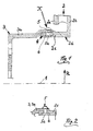
- Figure 1 shows a partial section of a composite brake disc according to the invention and Figure 2 in the form of a section X of Figure 1 shows a slight modification thereof.
- the so-called projection branches off from one of the friction rings of the brake disk, alternatively, however, the so-called projection can also be a component of a so-called driver, on which in turn the friction ring or a plurality of friction rings is fastened ,
- the reference numeral 1 is now the axis of rotation of the composite brake disc referred to, consisting of a friction ring 2 and a brake disc pot. 3 is composed.
- this joint 4 is characterized formed that from the inner periphery of the friction ring 2 with respect to the Rotary axis 1 circular cylindrical and thus to this parallel projection 2c protrudes, on which the brake disk cup 3 with a ring section his coat 3a rests.
- the joint 4, i. the connection between the jacket 3a of the brake disk hub 3 and the projection 2c the friction ring 2 formed as a press or shrink fit.
- all the exemplary embodiments are a ventilated friction ring 2 with a front annular disc 2a and a rear annular disc 2b, however, the present invention also in a massive (single) friction ring is implemented.
- the lead 2c from the rear (right) washer 2b to a sufficiently wide Friction surface 2 d to create on the inner wall of this projection 2 c, which then especially for a duo-servo parking brake, generally for one Drum brake, can be used.
- this depression 6, which in a further development as with respect to the axis of rotation 1 circumferential groove can be formed, a Range of increased elasticity, as well as a range of increased elasticity on Jacket 3a of the brake disk hub 3 is present near the joint 4, where the Jacket 3a has a reduced wall thickness. Because of these elasticities In particular, thermal stresses can be different Thermal expansion coefficients of the individual components of the composite brake disc result, at least partially compensated, as well as this principle already in the cited DE 100 32 972 A1 is described.
- the brake disk hub 3 in a high-strength light metal alloy (eg. AlSi7Mg), while the friction ring 2 with the projection 2c in a suitable casting material can be executed.
- a high-strength light metal alloy eg. AlSi7Mg
- the friction ring 2 with the projection 2c in a suitable casting material can be executed.
- the lead 2c is a component of a driver carrying the friction ring (s)
- a suitable steel in question It is still on it pointed out that a variety of details in particular constructive nature quite different from the embodiment shown be designed can, without leaving the content of the claims.
Description
Die Erfindung betrifft eine Verbund-Bremsscheibe für eine Fahrzeug-Scheibenbremse mit einem Bremsscheibentopf, an dem ein Bremsscheiben-Reibring oder ein den oder die Reibringe tragender Mitnehmer abseits der Reibring-Ebene über einen geeigneten Vorsprung befestigt ist, wozu der sich parallel zur Bremsscheiben-Drehachse erstreckende im wesentlichen ringförmige Vorsprung in Radialrichtung betrachtet bevorzugt innerhalb der in diesem Befestigungsbereich gegebenenfalls geringfügig geschwächten Wand des Bremsscheibentopfes liegt und Nieten oder ähnliche Verbindungselemente zwischen der Topfwand und dem Vorsprung vorgesehen sind. Zum technischen Umfeld wird auf die DE 100 32 972 A1 verwiesen.The invention relates to a composite brake disc for a vehicle disc brake with a brake disk pot on which a brake disc friction ring or a driver carrying the friction ring or rings away from the Friction ring level is attached via a suitable projection, to which the itself extending substantially parallel to the brake disc axis of rotation annular projection viewed in the radial direction preferably within the possibly slightly weakened in this attachment area Wall of the brake disc pot is and rivets or similar fasteners provided between the pot wall and the projection are. For the technical environment reference is made to DE 100 32 972 A1.
Verbund-Bremsscheiben an sich sind zumindest im druckschriftlichen Stand der Technik in unterschiedlichen Ausführungsarten bekannt und zeichnen sich durch den Vorteil aus, dass der Bremsscheiben-Reibring einerseits, auf welchem bekanntermaßen die Reibbeläge der Scheibenbremse zum Anliegen gebracht werden, und der sog. Bremsscheibentopf andererseits, mit welchen die Scheibenbremse an einem Radträger oder dgl. des Fahrzeugs befestigt wird, aus für die jeweiligen Anforderungen günstigen Materialien gefertigt sein können. Hierdurch kann bspw. zum einen eine Gewichtsersparnis erzielt werden, und zum anderen ist damit eine vorteilhafte Entkoppelung zwischen dem Reibring und dem Bremsscheibentopf möglich. Zumindest an Großserien-Personenkraftwagen, bei denen aufgrund der erforderlichen Abbremsung aus teilweise hohen Geschwindigkeiten hohe Anforderungen an die Bremsscheibe gestellt werden, haben sich solche Verbund-Bremsscheiben noch nicht durchgesetzt. Gleiches gilt für Verbund-Bremsscheiben mit sog. Mitnehmern, die die eigentlichen Reibringe tragen, und für die ein Beispiel in der (nicht vorveröffentlichten) deutschen Patentanmeldung 101 04 039.3 gezeigt ist.Composite brake discs per se are at least in the printed version The technique known and drawn in different embodiments characterized by the advantage that the brake disc friction ring on the one hand, on which is known to the friction linings of the disc brake for Concern be brought, and the so-called brake disk pot on the other hand, with which the disc brake on a wheel or the like. Of the Vehicle is fastened, favorable for the respective requirements Materials can be made. As a result, for example, on the one hand a Weight savings can be achieved, and on the other hand is thus an advantageous Decoupling between the friction ring and the brake disc hub possible. At least on mass-produced passenger cars, due to the required deceleration from partially high speeds high Requirements are made on the brake disc, such have Composite brake discs not yet enforced. The same applies to composite brake discs with so-called carriers, which carry the actual friction rings, and for the example in the (not previously published) German patent application 101 04 039.3 is shown.
In der eingangs genannten DE 100 32 972 ist eine Verbund-Bremsscheibe nach dem Oberbegriff des Anspruchs 1 aufgezeigt, die die wesentlichen Anforderungen in nahezu optimaler Weise erfüllen kann, jedoch ist diese bekannte Verbund-Bremsscheibe optimal für diejenigen Räder eines Fahrzeugs geeignet, an denen lediglich eine Betriebsbremse (in Form der Scheibenbremse) angreift. Für eine weitere Hilfsbremse, die bevorzugt auch als Feststellbremse fungieren kann, und die üblicherweise in Form einer Trommelbremse ausgebildet ist, ist die bekannte Verbund-Bremsscheibe wegen des Fehlens einer ausreichend breiten Anlauffläche für die Bremsbeläge einer Trommelbremse weniger geeignet. Theoretisch könnte zwar auch die Innenwand des Bremsscheibentopfes als Anlauffläche einer Trommelbremse fungieren, jedoch ist dies dann ausgeschlossen, wenn der Bremsscheibentopf in einer Leichtmetall-Legierung ausgeführt ist, was unter Gewichts-Gesichtspunkten nicht nur vorteilhaft ist, sondern insbesondere dann, wenn eine höherfeste Leichtmetall-Legierung zum Einsatz kommt, unter Festigkeits-Gesichtspunkten auch möglich ist.In the aforementioned DE 100 32 972 is a composite brake disc according to the preamble of claim 1, showing the essential Meet requirements in almost optimal way, but this is known compound brake disc optimal for those wheels one Suitable vehicles, where only a service brake (in the form of Disc brake) attacks. For another auxiliary brake, the preferred too can act as a parking brake, and usually in the form of a Drum brake is formed, the known compound brake disc because of the lack of a sufficiently wide contact surface for the brake pads a drum brake less suitable. Theoretically, too the inner wall of the brake disk hub as a contact surface of a drum brake However, this is then ruled out when the disc brake cup executed in a light metal alloy, which is under Weight aspects is not only advantageous, but in particular when a higher strength light metal alloy is used, under strength aspects is also possible.
Hiermit soll nun eine Verbundbremsscheibe nach dem Oberbegriff des Anspruchs 1 aufgezeigt werden, die nicht nur als Scheibenbremse, sondern auch als Trommelbremse fungieren kann, und somit bspw. für eine Duo-Servo-Bremse an der Hinterachse von Personenkraftwagen eingesetzt werden kann (= Aufgabe der vorliegenden Erfindung). Herewith, a composite brake disk according to the preamble of Claim 1 are shown, not only as a disc brake, but can also act as a drum brake, and thus, for example, for a duo servo brake used on the rear axle of passenger cars can be (= object of the present invention).
Die Lösung dieser Aufgabe ist dadurch gekennzeichnet, dass die (genannten) Verbindungselemente (zwischen dem Bremsscheibentopf und dem Vorsprung des Reibrings bzw. Mitnehmers) in Radialrichtung derart weit außen liegen, dass die der Drehachse zugewandte Innenwand des Vorsprungs als Anlauffläche einer Trommelbremse fungieren kann. Vorteilhafte Aus- und Weiterbildungen sind Inhalt der Unteransprüche.The solution to this problem is characterized in that the (mentioned) Connecting elements (between the brake disc chamber and the Projection of the friction ring or driver) in the radial direction so far lie outside, that the axis of rotation facing inner wall of the projection can act as a contact surface of a drum brake. advantageous Training and further education are content of the dependent claims.
Erfindungsgemäß übernimmt der sog. Vorsprung eines Reibrings oder Reibring-Mitnehmers, an dem (im Hinblick auf die mechanische und thermische Bremsscheibenbelastung wie in der eingangs genannten Schrift angegeben besonders günstig) der Bremsscheibentopf befestigt ist, gleichzeitig die Funktion einer Anlauffläche für eine Trommelbremse, d.h. der sog. Vorsprung fungiert gleichzeitig als Bremstrommel. Dabei ist es durchaus denkbar, dass der Vorsprung in Axialrichtung betrachtet lediglich einen Teilbereich der Bremstrommel bildet, wenn auch an der Innenseite des sich in Axialrichtung an die Innenwand des Vorsprungs anschließenden Topfwand (des Bremsscheibentopfes) die Reibbeläge der Trommelbremse zum Anliegen gebracht werden können. Letzteres ist jedoch evtl. weniger günstig, wenn der Bremsscheibentopf in einer bevorzugt höherfesten Leichtmetall-Legierung ausgeführt ist, jedoch ist die vorliegende Erfindung - obwohl ein derartiges Material unbestreitbare Vorzüge hat - nicht auf ein solches Bremsscheibentopf-Material beschränkt.According to the invention takes over the so-called. Projection of a friction ring or Friction ring driver on which (in terms of mechanical and thermal brake disk load as in the above-mentioned document specified particularly favorable) the brake disc hub is attached, at the same time the function of a stop surface for a drum brake, i. of the so-called projection also acts as a brake drum. It is quite conceivable that the projection viewed in the axial direction only one Part of the brake drum forms, although on the inside of itself in the axial direction of the inner wall of the projection adjoining pot wall (brake disc cup) the friction linings of the drum brake to Concerns can be brought. The latter may be less favorable if the brake disk pot in a preferably higher-strength light metal alloy is executed, however, the present invention - although a Such material has indisputable merits - not on such Brake disc pot material limited.
Wie in der bereits genannten DE 100 32 972 A1 angegeben, kann es ausreichend sein, den Fügebereich bw. die Fügestelle zwischen dem Vorsprung und dem Bremsscheibentopf als Press- oder Schrumpfsitz auszubilden, jedoch erhöhen zusätzliche, im wesentlichen in Radialrichtung (bezüglich der Bremsscheiben-Drehachse) vorgesehene Verbindungselemente, bei denen es sich bspw. um Nieten, aber auch um Schrauben oder dgl. handeln kann, die Sicherheit dieses Verbundes. Dann jedoch sollten diese Verbindungselemente so angeordnet sein, dass sie die Funktion der Vorsprung-Innenwand als Anlauffläche einer Trommelbremse nicht stören. Allgemein betrachtet sind also die Verbindungselemente als Ganzes hierfür in Radialrichtung soweit außen, d.h. von der Bremsscheiben-Drehachse entfernt angeordnet, dass die Bremsbeläge der Trommelbremse beim Betätigen derselben, d.h. beim Anlegen an die Innenwand des Vorsprungs, mit diesen Verbindungselementen nicht in Kontakt kommen können.As stated in the already mentioned DE 100 32 972 A1, it can be sufficient, the joining area bw. the joint between the Projection and the brake disk pot as a press or shrink fit form, but increase additional, substantially in the radial direction (with respect to the brake disc axis of rotation) provided connecting elements, which are, for example, to rivets, but also to screws or The like can act, the security of this network. Then, however, should these fasteners may be arranged to perform the function of Do not disturb the projection inner wall as the contact surface of a drum brake. Generally speaking, therefore, the fasteners as a whole are for this in the radial direction as far outside, i. from the brake disc rotation axis arranged away the brake pads of the drum brake when Actuating the same, i. when applied to the inner wall of the projection, can not come into contact with these fasteners.
Konkret kann hierfür ein Kopfteil oder dgl. der Verbindungselemente zumindest im wesentlichen in der Wand des Vorsprungs versenkt sein, so bspw. ein Nietkopf oder ein Schraubenkopf oder ähnliches, so dass das Bremselement oder der Bremsbelag der Trommelbremse an die Vorsprung-Wand angelegt werden kann, ohne hierbei - wenn die Bremsscheibe und somit die Bremstrommel rotiert - in Kontakt mit den Verbindungselementen zu kommen. Sollte dieses Versenken in der Wand des Vorsprungs nicht soweit wie eigentlich erforderlich möglich sein, da für die Funktionserfüllung des Verbindungselementes noch eine gewisse Rest-Wandstärke des Vorsprungs benötigt wird, so kann ein Kopfteil oder dgl. der Verbindungselemente nach Herstellen der Verbindung soweit mechanisch abgetragen oder umgeformt werden, dass die der Drehachse zugewandte Innenwand des Vorsprungs in jedem Fall problemlos als Anlauffläche einer Trommelbremse fungieren kann.Specifically, this can be a head part or the like. Of the connecting elements be sunk at least substantially in the wall of the projection, so For example, a rivet head or a screw head or the like, so that the Brake element or the brake lining of the drum brake to the projection wall can be created without this - if the brake disc and thus the brake drum rotates - in contact with the connecting elements get. Should not this sinking in the wall of the tab as far as actually necessary to be possible, there for the function fulfillment the connecting element still has a certain residual wall thickness of the Projection is required, so can a headboard or the like. The fasteners mechanically removed after the connection has been made or be formed, that the rotation axis facing inner wall the projection in each case easily as a contact surface of a drum brake can act.
Es sei noch darauf hingewiesen, dass die Topfwand, d.h. die Wand bzw. der Mantel des Bremsscheibentopfes im sog. Befestigungsbereich, in dem die Verbindung mit dem sog. Vorsprung des Reibringes oder des genannten Reibring-Mitnehmers hergestellt ist, zumindest geringfügig geschwächt sein kann, um eine gewisse Elastizität zu schaffen, jedoch handelt es sich hierbei um kein für die Funktion der vorliegenden Erfindung erforderliches Merkmal. Auch muss der sog. Vorsprung nicht über seiner gesamten axialen Länge einen geschlossenen Kreisring bzw. geschlossenen kreisförmigen Zylinder bilden, sondern kann durchaus zumindest abschnittsweise in Umfangsrichtung nebeneinander angeordnete und dabei voneinander getrennte Vorsprünge oder Zungen oder dgl. aufweisen, weshalb der Vorsprung im vorangegangenen Text als "im wesentlichen ringförmig" beschrieben wurde. Ferner sei noch erwähnt, dass der im wesentlichen ringförmige Vorsprung in Radialrichtung betrachtet zwar bevorzugt innerhalb der Wand oder dem Mantel des Bremsscheibentopfes liegt, alternativ jedoch auch in Radialrichtung von außen an der Topfwand anliegen kann.It should be noted that the pot wall, i. the wall or the Mantel of the brake disk hub in the so-called. Attachment area in which the Connection with the so-called. Projection of the friction ring or said Friction ring driver is made to be at least slightly weakened can, to create a certain elasticity, but this is no feature required for the function of the present invention. Also, the so-called projection does not have to be over its entire axial length a closed circular ring or closed circular cylinder form, but can certainly at least partially in the circumferential direction juxtaposed and separated from each other Projections or tongues or the like., Which is why the projection in previous text was described as "substantially annular". It should also be mentioned that the substantially annular projection in Although radial direction preferably viewed within the wall or the Jacket of the brake disk pot is, but alternatively also in the radial direction from the outside can rest against the pot wall.
Im folgenden wird die Erfindung anhand eines bevorzugten Ausführungsbeispieles weiter erläutert, wobei die beigefügte Figur 1 einen Teil-Schnitt einer erfindungsgemäßen Verbund-Bremsscheibe und Figur 2 in Form eines Ausschnitts X aus Fig.1 eine geringfügige Abwandlung hiervon zeigt. Dabei sei ausdrücklich darauf hingewiesen, dass zwar hier der sog. Vorsprung von einem der Reibringe der Bremsscheibe abzweigt, dass alternativ jedoch der sog. Vorsprung auch ein Bestandteil eines sog. Mitnehmers sein kann, an dem wiederum der Reibring oder mehrere Reibringe befestigt ist/sind.In the following the invention with reference to a preferred embodiment will be further explained, wherein the accompanying Figure 1 shows a partial section of a composite brake disc according to the invention and Figure 2 in the form of a section X of Figure 1 shows a slight modification thereof. It should be expressly pointed out that although here the so-called projection branches off from one of the friction rings of the brake disk, alternatively, however, the so-called projection can also be a component of a so-called driver, on which in turn the friction ring or a plurality of friction rings is fastened ,
Mit der Bezugsziffer 1 ist nun die Drehachse der Verbund-Bremsscheibe
bezeichnet, die aus einem Reibring 2 sowie einem Bremsscheibentopf 3
zusammengesetzt ist. In einer sog. Fügestelle 4 sind diese beiden Elemente
miteinander verbunden. Wie ersichtlich ist diese Fügestelle 4 dadurch
gebildet, dass vom Innenumfang des Reibringes 2 ein bezüglich der
Drehachse 1 kreiszylindrischer und somit zu dieser paralleler Vorsprung 2c
abragt, auf welchem der Bremsscheibentopf 3 mit einem Ringabschnitt
seines Mantels 3a aufliegt. Dabei ist die Fügestelle 4, d.h. die Verbindung
zwischen dem Mantel 3a des Bremsscheibentopfes 3 und dem Vorsprung 2c
des Reibringes 2 als Preß- oder Schrumpfsitz ausgebildet.The reference numeral 1 is now the axis of rotation of the composite brake disc
referred to, consisting of a
Wie ersichtlich handelt es sich bei sämtlichen Ausführungsbeispielen um
einen belüfteten Reibring 2 mit einer vorderen Ringscheibe 2a und einer
hinteren Ringscheibe 2b, wobei die vorliegende Erfindung jedoch ebenso bei
einem massiven (einzigen) Reibring umsetzbar ist. Hier ragt der Vorsprung
2c von der hinteren (rechten) Ringscheibe 2b ab, um eine ausreichend breite
Reibfläche 2d an der Innenwand dieses Vorsprungs 2c zu schaffen, die dann
insbesondere für eine Duo-Servo-Feststellbremse, allgemein für eine
Trommelbremse, herangezogen werden kann.As can be seen, all the exemplary embodiments are
a ventilated
Wie ersichtlich ist die als Preß- oder Schrumpfsitz ausgebildete Fügestelle 4
durch zumindest ein, insbesondere jedoch mehrere über dem Umfang
verteilt angeordnete, im wesentlichen senkrecht zur Drehachse 1 (d.h. in
Radialrichtung R) ausgerichtete(s) Verbindungselement(e) 5 gesichert, das
bzw. die hier in Form eines Nietes ausgebildet ist/sind, das/die aber auch als
Schraube oder in ähnlicher Weise wirkend ausgebildet sein kann.As can be seen, the formed as a press or
Wie ersichtlich ist es praktisch kaum möglich, bei Einhaltung einer üblichen
bzw. kleinstmöglichen Bauraum-Breite eine ausreichend breite Reibfläche 2d
(in Richtung der Drehachse 1 gemessen) für eine Trommelbremse zu
erhalten, ohne dass in dieser Reibfläche 2d das oder die Verbindungselement(e)
5 zum Liegen kommt/kommen. Um zu verhindern, dass diese
Verbindungselemente 5 gravierende Störstellen für den auf der Reibfläche
2d anliegenden Bremsbelag der Trommelbremse bilden, liegen diese in
Radialrichtung R betrachtet soweit außen als möglich, d.h. von der Drehachse
1 beabstandet, was dadurch erreicht ist, dass ein Kopfteil 5a jedes
Verbindungselements 5 in der Wand des Vorsprungs 2c bzw. in einer darin
eingebrachten Einsenkung 6 versenkt ist.As can be seen, it is practically impossible, while maintaining a common
or smallest possible space width a sufficiently
Vorteilhafterweise bildet diese Einsenkung 6, die in einer Weiterbildung als
bezüglich der Drehachse 1 umlaufende Nut ausgebildet sein kann, einen
Bereich erhöhter Elastizität, ebenso wie ein Bereich erhöhter Elastizität am
Mantel 3a des Bremsscheibentopfs 3 nahe der Fügestelle 4 vorliegt, wo der
Mantel 3a eine verringerte Wandstärke besitzt. Aufgrund dieser Elastizitäten
können insbesondere thermische Spannungen, die aus unterschiedlichen
Wärmeausdehnungskoeffizienten der einzelnen Bestandteile des Verbundbremsscheibe
resultieren, zumindest teilweise kompensiert werden, so wie
dies grundsätzlich bereits in der mehrfach genannten DE 100 32 972 A1
beschrieben ist.Advantageously, this
Zurückkommend auf die Verbindungselemente 5 bzw. deren Anordnung
solchermaßen, dass sie keine Störstelle in der Reibfläche 2d bzw. Anlauffläche
der Trommelbremse bilden ist es möglich, das innenliegende, d.h. im
Bereich der Reibfläche 2d liegende Kopfteil 5a jedes Verbindungselements
nach dem Herstellen dieser Verbindung (d.h. nach dem Einsetzen des
Verbindungselements 5) soweit mechanisch abzutragen oder umzuformen,
dass die der Drehachse 1 zugewandte Innenwand 2d (bzw. Reibfläche 2d)
des Vorsprungs 2c als Anlauffläche einer Trommelbremse fungieren kann.Coming back to the connecting
Zur Gewichtsreduktion der erfindungsgemäßen Verbund-Bremsscheibe kann
der Bremsscheibentopf 3 in einer höherfesten Leichtmetall-Legierung (bspw.
AlSi7Mg) ausgeführt sein, während der Reibring 2 mit dem Vorsprung 2c in
einem geeigneten Gussmaterial ausgeführt sein kann. Wenn der Vorsprung
2c ein Bestandteil eines den oder die Reibring(e) tragenden Mitnehmers ist,
kommt hierfür auch ein geeigneter Stahl in Frage. Dabei sei noch darauf
hingewiesen, dass eine Vielzahl von Details insbesondere konstruktiver Art
durchaus abweichend vom gezeigten Ausführungsbeispiel gestaltet sein
kann, ohne den Inhalt der Patentansprüche zu verlassen.For weight reduction of the composite brake disc according to the invention can
the
Claims (4)
- A composite brake disc for a motor vehicle disc brake comprising a brake disc chamber (3) to which a brake disc friction ring (2) or an entrainment member carrying the friction ring or rings is fastened at a distance from the friction ring plane via a suitable projection (2c), for which purpose the substantially annular projection (2c), which extends parallel to the axis of rotation (1) of the brake disc, is preferably located, viewed in the radial direction (R), inside the wall (casing 3a) of the brake disc chamber and rivets or similar connecting elements (5) are provided between the chamber wall (casing 3a) and the projection (2c), characterised in that the connecting elements (5) are located sufficiently far out in the radial direction (R) that the internal wall (2d) of the projection (2c) that faces the axis of rotation (1) may act as the stop face of a drum brake.
- A composite brake disc according to claim 1, characterised in that a head part (5a) or the like of the connecting elements (5) is sunk at least substantially in the wall of the projection (2c).
- A composite brake disc according to either claim 1 or claim 2, characterised in that, after the connection has been produced, a head part (5a) or the like of the connecting elements (5) is mechanically excavated or shaped to the extent that the internal wall (2d) of the projection (2c) that faces the axis of rotation (1) may act as the stop face of a drum brake.
- A composite brake disc according to any one of the preceding claims, characterised in that the brake disc chamber (3) is made of a light metal alloy of relatively high strength and the friction ring (2) comprising the projection (2c) is made of a casting material or the entrainment member comprising the projection (2c) is made of steel.
Applications Claiming Priority (2)
| Application Number | Priority Date | Filing Date | Title |
|---|---|---|---|
| DE10217616 | 2002-04-19 | ||
| DE10217616A DE10217616A1 (en) | 2002-04-19 | 2002-04-19 | Composite brake disc for a vehicle disc brake |
Publications (3)
| Publication Number | Publication Date |
|---|---|
| EP1355075A2 EP1355075A2 (en) | 2003-10-22 |
| EP1355075A3 EP1355075A3 (en) | 2004-06-30 |
| EP1355075B1 true EP1355075B1 (en) | 2005-05-25 |
Family
ID=28458936
Family Applications (1)
| Application Number | Title | Priority Date | Filing Date |
|---|---|---|---|
| EP03004698A Expired - Lifetime EP1355075B1 (en) | 2002-04-19 | 2003-03-04 | Assembled brake disc for a vehicle disc brake |
Country Status (2)
| Country | Link |
|---|---|
| EP (1) | EP1355075B1 (en) |
| DE (2) | DE10217616A1 (en) |
Cited By (2)
| Publication number | Priority date | Publication date | Assignee | Title |
|---|---|---|---|---|
| DE202016102524U1 (en) | 2016-04-27 | 2016-06-23 | Fritz Winter Eisengiesserei Gmbh & Co. Kg | Brake disc for a vehicle |
| DE102017207139A1 (en) | 2017-04-27 | 2018-10-31 | Robert Bosch Gmbh | Brake disc assembly for a disc brake of a motor vehicle, method |
Families Citing this family (11)
| Publication number | Priority date | Publication date | Assignee | Title |
|---|---|---|---|---|
| WO2007049312A1 (en) * | 2005-10-28 | 2007-05-03 | Brembo Ceramic Brake Systems S.P.A. | Parking brake |
| DE102007053576B4 (en) * | 2007-11-09 | 2017-08-03 | Dr. Ing. H.C. F. Porsche Aktiengesellschaft | braking device |
| KR20100035258A (en) * | 2008-09-26 | 2010-04-05 | 주식회사 데크 | Dih structure brake disk with drum for parking brake and disk roter for disc brake formed integrally |
| DE102010037123B4 (en) * | 2010-08-23 | 2020-08-06 | Leiber Group Gmbh & Co. Kg Aluminium Umform- Und Bearbeitungstechnik | Brake system with a brake disc chamber, a drum and at least one friction ring as a brake disc and method for manufacturing |
| DE102013002300B3 (en) * | 2013-02-08 | 2014-07-17 | Audi Ag | Brake disc for a disc brake of a motor vehicle |
| DE102015110104A1 (en) * | 2015-06-24 | 2016-12-29 | Dr. Ing. H.C. F. Porsche Aktiengesellschaft | Brake disc device for a vehicle |
| US9982732B2 (en) | 2015-08-04 | 2018-05-29 | Gri Engineering & Development, Llc | Vehicle brake rotor and method of making same |
| DE102018212862A1 (en) | 2017-08-02 | 2019-02-07 | Robert Bosch Gmbh | Brake disc and method for producing a brake disc |
| DE102018009194A1 (en) * | 2018-11-22 | 2020-05-28 | Zf Active Safety Gmbh | Brake disc for a vehicle disc brake |
| DE102019213751A1 (en) | 2019-01-11 | 2020-07-16 | Continental Teves Ag & Co. Ohg | Built composite brake drum for a motor vehicle |
| GB2583525A (en) * | 2019-05-03 | 2020-11-04 | Eurac Ltd | Brake disks |
Family Cites Families (7)
| Publication number | Priority date | Publication date | Assignee | Title |
|---|---|---|---|---|
| US4854423A (en) * | 1988-07-26 | 1989-08-08 | Kelsey Hayes Company | Hydraulic disc brake drum-in-hat parking brake assembly |
| US5385216A (en) * | 1993-06-04 | 1995-01-31 | The Budd Company | Composite rear brake disc and drum |
| DE4419757A1 (en) * | 1994-06-06 | 1995-12-07 | Teves Gmbh Alfred | Brake disc with friction ring and sheet metal holding dish |
| DE19652464A1 (en) * | 1996-12-17 | 1998-06-18 | Bayerische Motoren Werke Ag | Compound brake disc |
| EP1128084A3 (en) * | 2000-02-23 | 2003-10-29 | Bayerische Motoren Werke Aktiengesellschaft | Method for manufacturing a brake disc |
| DE10032972B4 (en) * | 2000-07-06 | 2004-04-15 | Bayerische Motoren Werke Ag | Composite brake disc for a vehicle disc brake |
| DE10104039A1 (en) * | 2001-01-31 | 2002-08-01 | Bayerische Motoren Werke Ag | Multiple-section brake disc esp. for motor vehicles has two friction rings of steel or ceramics, and drive plate, spacers, and fasteners of steel, carbon, or alloys |
-
2002
- 2002-04-19 DE DE10217616A patent/DE10217616A1/en not_active Withdrawn
-
2003
- 2003-03-04 DE DE50300567T patent/DE50300567D1/en not_active Expired - Lifetime
- 2003-03-04 EP EP03004698A patent/EP1355075B1/en not_active Expired - Lifetime
Cited By (5)
| Publication number | Priority date | Publication date | Assignee | Title |
|---|---|---|---|---|
| DE202016102524U1 (en) | 2016-04-27 | 2016-06-23 | Fritz Winter Eisengiesserei Gmbh & Co. Kg | Brake disc for a vehicle |
| WO2017186867A1 (en) | 2016-04-27 | 2017-11-02 | Fritz Winter Eisengiesserei Gmbh & Co. Kg | Brake disc for a vehicle |
| DE102016107823A1 (en) | 2016-04-27 | 2017-11-02 | Fritz Winter Eisengiesserei Gmbh & Co. Kg | Brake disc for a vehicle |
| DE102017207139A1 (en) | 2017-04-27 | 2018-10-31 | Robert Bosch Gmbh | Brake disc assembly for a disc brake of a motor vehicle, method |
| WO2018197321A1 (en) | 2017-04-27 | 2018-11-01 | Robert Bosch Gmbh | Brake disc assembly for a disc brake of a motor vehicle, and method |
Also Published As
| Publication number | Publication date |
|---|---|
| EP1355075A2 (en) | 2003-10-22 |
| DE50300567D1 (en) | 2005-06-30 |
| DE10217616A1 (en) | 2003-11-06 |
| EP1355075A3 (en) | 2004-06-30 |
Similar Documents
| Publication | Publication Date | Title |
|---|---|---|
| DE19581383B4 (en) | Method for mounting a lockable clutch for a hydrodynamic transmission, in particular for motor vehicles, corresponding lockable clutch and hydrodynamic transmission with such a lockable clutch | |
| EP3033540B1 (en) | Brake disc for a vehicle | |
| DE10032972B4 (en) | Composite brake disc for a vehicle disc brake | |
| EP2553290B1 (en) | Brake disc | |
| EP1355075B1 (en) | Assembled brake disc for a vehicle disc brake | |
| EP3212433B1 (en) | Vehicle wheel having a connection between a wheel rim and a wheel disc and method for the production thereof | |
| DE102008044136A1 (en) | Wheel carrier of a motor vehicle | |
| EP1426644B1 (en) | Assembled brake disc for a vehicle disc brake | |
| DE102014017715A1 (en) | Pneumatically or electromechanically actuated disc brake for commercial vehicles | |
| DE102009010747A1 (en) | Brake disk for use in disk brake of brake system of passenger car, has friction ring with opening, and cup rolling in opening, where lug is provided at edge of cup, and recess is provided at edge of friction ring | |
| DE102017116681B3 (en) | brake disc | |
| EP3394468B1 (en) | Brake disc for a vehicle | |
| DE102016225155A1 (en) | Wheel bearing unit and wheel carrier | |
| EP2507530B1 (en) | Wheel assembly | |
| DE10254110B4 (en) | Brake disc with a friction ring made of a substantially non-metallic material | |
| DE102010004866A1 (en) | Retaining arrangement of a brake disc on a wheel hub of a motor vehicle | |
| EP3795853B1 (en) | Rail wheel comprising a brake disc with a segmented friction ring | |
| DE19858243B4 (en) | Brake disc for disc brakes | |
| EP1335144B1 (en) | Brake support assembly | |
| DE102016107823A1 (en) | Brake disc for a vehicle | |
| DE102019103801A1 (en) | Assembled brake disc and method of making such a brake disc | |
| DE102008031709A1 (en) | Disk brake arrangement for vehicle, particularly for commercial motor vehicle, has disk brake with brake carrier and axial side carrier element, particularly knuckle or brake flange | |
| DE102021213374B4 (en) | Disc brake system with one-sided pressurization | |
| EP1162384A2 (en) | Vehicle brake disc with friction ring and hub part made from different materials | |
| DE19723036A1 (en) | Drum for brake on automobile, includes housing |
Legal Events
| Date | Code | Title | Description |
|---|---|---|---|
| PUAI | Public reference made under article 153(3) epc to a published international application that has entered the european phase |
Free format text: ORIGINAL CODE: 0009012 |
|
| AK | Designated contracting states |
Kind code of ref document: A2 Designated state(s): AT BE BG CH CY CZ DE DK EE ES FI FR GB GR HU IE IT LI LU MC NL PT RO SE SI SK TR |
|
| AX | Request for extension of the european patent |
Extension state: AL LT LV MK |
|
| PUAL | Search report despatched |
Free format text: ORIGINAL CODE: 0009013 |
|
| AK | Designated contracting states |
Kind code of ref document: A3 Designated state(s): AT BE BG CH CY CZ DE DK EE ES FI FR GB GR HU IE IT LI LU MC NL PT RO SE SI SK TR |
|
| AX | Request for extension of the european patent |
Extension state: AL LT LV MK |
|
| 17P | Request for examination filed |
Effective date: 20040714 |
|
| GRAP | Despatch of communication of intention to grant a patent |
Free format text: ORIGINAL CODE: EPIDOSNIGR1 |
|
| GRAS | Grant fee paid |
Free format text: ORIGINAL CODE: EPIDOSNIGR3 |
|
| AKX | Designation fees paid |
Designated state(s): DE FR GB IT |
|
| GRAA | (expected) grant |
Free format text: ORIGINAL CODE: 0009210 |
|
| AK | Designated contracting states |
Kind code of ref document: B1 Designated state(s): DE FR GB IT |
|
| REG | Reference to a national code |
Ref country code: GB Ref legal event code: FG4D Free format text: NOT ENGLISH |
|
| GBT | Gb: translation of ep patent filed (gb section 77(6)(a)/1977) |
Effective date: 20050525 |
|
| REG | Reference to a national code |
Ref country code: IE Ref legal event code: FG4D Free format text: LANGUAGE OF EP DOCUMENT: GERMAN |
|
| REF | Corresponds to: |
Ref document number: 50300567 Country of ref document: DE Date of ref document: 20050630 Kind code of ref document: P |
|
| ET | Fr: translation filed | ||
| PLBE | No opposition filed within time limit |
Free format text: ORIGINAL CODE: 0009261 |
|
| STAA | Information on the status of an ep patent application or granted ep patent |
Free format text: STATUS: NO OPPOSITION FILED WITHIN TIME LIMIT |
|
| 26N | No opposition filed |
Effective date: 20060228 |
|
| REG | Reference to a national code |
Ref country code: FR Ref legal event code: PLFP Year of fee payment: 14 |
|
| REG | Reference to a national code |
Ref country code: FR Ref legal event code: PLFP Year of fee payment: 15 |
|
| REG | Reference to a national code |
Ref country code: FR Ref legal event code: PLFP Year of fee payment: 16 |
|
| PGFP | Annual fee paid to national office [announced via postgrant information from national office to epo] |
Ref country code: GB Payment date: 20220324 Year of fee payment: 20 Ref country code: DE Payment date: 20220316 Year of fee payment: 20 |
|
| PGFP | Annual fee paid to national office [announced via postgrant information from national office to epo] |
Ref country code: FR Payment date: 20220323 Year of fee payment: 20 |
|
| PGFP | Annual fee paid to national office [announced via postgrant information from national office to epo] |
Ref country code: IT Payment date: 20220331 Year of fee payment: 20 |
|
| REG | Reference to a national code |
Ref country code: DE Ref legal event code: R071 Ref document number: 50300567 Country of ref document: DE |
|
| REG | Reference to a national code |
Ref country code: GB Ref legal event code: PE20 Expiry date: 20230303 |
|
| PG25 | Lapsed in a contracting state [announced via postgrant information from national office to epo] |
Ref country code: GB Free format text: LAPSE BECAUSE OF EXPIRATION OF PROTECTION Effective date: 20230303 |
|
| P01 | Opt-out of the competence of the unified patent court (upc) registered |
Effective date: 20230427 |