EP2340344B1 - Vorrichtung mit wenigstens einem integrierten scharnier aus verbundmaterial mit einer ununterbrochenen verbundverstärkung - Google Patents
Vorrichtung mit wenigstens einem integrierten scharnier aus verbundmaterial mit einer ununterbrochenen verbundverstärkung Download PDFInfo
- Publication number
- EP2340344B1 EP2340344B1 EP09752409.4A EP09752409A EP2340344B1 EP 2340344 B1 EP2340344 B1 EP 2340344B1 EP 09752409 A EP09752409 A EP 09752409A EP 2340344 B1 EP2340344 B1 EP 2340344B1
- Authority
- EP
- European Patent Office
- Prior art keywords
- flexible
- stiff
- portions
- hinge
- composite material
- Prior art date
- Legal status (The legal status is an assumption and is not a legal conclusion. Google has not performed a legal analysis and makes no representation as to the accuracy of the status listed.)
- Active
Links
Images


Classifications
-
- E—FIXED CONSTRUCTIONS
- E05—LOCKS; KEYS; WINDOW OR DOOR FITTINGS; SAFES
- E05D—HINGES OR SUSPENSION DEVICES FOR DOORS, WINDOWS OR WINGS
- E05D1/00—Pinless hinges; Substitutes for hinges
- E05D1/02—Pinless hinges; Substitutes for hinges made of one piece
-
- A—HUMAN NECESSITIES
- A45—HAND OR TRAVELLING ARTICLES
- A45C—PURSES; LUGGAGE; HAND CARRIED BAGS
- A45C13/00—Details; Accessories
- A45C13/005—Hinges
-
- B—PERFORMING OPERATIONS; TRANSPORTING
- B64—AIRCRAFT; AVIATION; COSMONAUTICS
- B64G—COSMONAUTICS; VEHICLES OR EQUIPMENT THEREFOR
- B64G1/00—Cosmonautic vehicles
- B64G1/22—Parts of, or equipment specially adapted for fitting in or to, cosmonautic vehicles
- B64G1/222—Parts of, or equipment specially adapted for fitting in or to, cosmonautic vehicles for deploying structures between a stowed and deployed state
- B64G1/2221—Parts of, or equipment specially adapted for fitting in or to, cosmonautic vehicles for deploying structures between a stowed and deployed state characterised by the manner of deployment
- B64G1/2222—Folding
-
- B—PERFORMING OPERATIONS; TRANSPORTING
- B29—WORKING OF PLASTICS; WORKING OF SUBSTANCES IN A PLASTIC STATE IN GENERAL
- B29C—SHAPING OR JOINING OF PLASTICS; SHAPING OF MATERIAL IN A PLASTIC STATE, NOT OTHERWISE PROVIDED FOR; AFTER-TREATMENT OF THE SHAPED PRODUCTS, e.g. REPAIRING
- B29C53/00—Shaping by bending, folding, twisting, straightening or flattening; Apparatus therefor
- B29C53/02—Bending or folding
- B29C53/04—Bending or folding of plates or sheets
- B29C53/06—Forming folding lines by pressing or scoring
- B29C53/063—Forming folding lines by pressing or scoring combined with folding
- B29C53/066—Forming folding lines by pressing or scoring combined with folding and joining the sides of the folding line, e.g. "Abkantschweissen"
-
- E—FIXED CONSTRUCTIONS
- E05—LOCKS; KEYS; WINDOW OR DOOR FITTINGS; SAFES
- E05D—HINGES OR SUSPENSION DEVICES FOR DOORS, WINDOWS OR WINGS
- E05D11/00—Additional features or accessories of hinges
- E05D11/06—Devices for limiting the opening movement of hinges
-
- E—FIXED CONSTRUCTIONS
- E05—LOCKS; KEYS; WINDOW OR DOOR FITTINGS; SAFES
- E05D—HINGES OR SUSPENSION DEVICES FOR DOORS, WINDOWS OR WINGS
- E05D9/00—Flaps or sleeves specially designed for making from particular material, e.g. hoop-iron, sheet metal, plastics
- E05D9/005—Flaps or sleeves specially designed for making from particular material, e.g. hoop-iron, sheet metal, plastics from plastics
-
- E—FIXED CONSTRUCTIONS
- E05—LOCKS; KEYS; WINDOW OR DOOR FITTINGS; SAFES
- E05F—DEVICES FOR MOVING WINGS INTO OPEN OR CLOSED POSITION; CHECKS FOR WINGS; WING FITTINGS NOT OTHERWISE PROVIDED FOR, CONCERNED WITH THE FUNCTIONING OF THE WING
- E05F1/00—Closers or openers for wings, not otherwise provided for in this subclass
- E05F1/08—Closers or openers for wings, not otherwise provided for in this subclass spring-actuated, e.g. for horizontally sliding wings
- E05F1/10—Closers or openers for wings, not otherwise provided for in this subclass spring-actuated, e.g. for horizontally sliding wings for swinging wings, e.g. counterbalance
- E05F1/12—Mechanisms in the shape of hinges or pivots, operated by springs
-
- E—FIXED CONSTRUCTIONS
- E05—LOCKS; KEYS; WINDOW OR DOOR FITTINGS; SAFES
- E05Y—INDEXING SCHEME ASSOCIATED WITH SUBCLASSES E05D AND E05F, RELATING TO CONSTRUCTION ELEMENTS, ELECTRIC CONTROL, POWER SUPPLY, POWER SIGNAL OR TRANSMISSION, USER INTERFACES, MOUNTING OR COUPLING, DETAILS, ACCESSORIES, AUXILIARY OPERATIONS NOT OTHERWISE PROVIDED FOR, APPLICATION THEREOF
- E05Y2800/00—Details, accessories and auxiliary operations not otherwise provided for
- E05Y2800/20—Combinations of elements
- E05Y2800/205—Combinations of elements forming a unit
-
- Y—GENERAL TAGGING OF NEW TECHNOLOGICAL DEVELOPMENTS; GENERAL TAGGING OF CROSS-SECTIONAL TECHNOLOGIES SPANNING OVER SEVERAL SECTIONS OF THE IPC; TECHNICAL SUBJECTS COVERED BY FORMER USPC CROSS-REFERENCE ART COLLECTIONS [XRACs] AND DIGESTS
- Y10—TECHNICAL SUBJECTS COVERED BY FORMER USPC
- Y10T—TECHNICAL SUBJECTS COVERED BY FORMER US CLASSIFICATION
- Y10T403/00—Joints and connections
- Y10T403/45—Flexibly connected rigid members
-
- Y—GENERAL TAGGING OF NEW TECHNOLOGICAL DEVELOPMENTS; GENERAL TAGGING OF CROSS-SECTIONAL TECHNOLOGIES SPANNING OVER SEVERAL SECTIONS OF THE IPC; TECHNICAL SUBJECTS COVERED BY FORMER USPC CROSS-REFERENCE ART COLLECTIONS [XRACs] AND DIGESTS
- Y10—TECHNICAL SUBJECTS COVERED BY FORMER USPC
- Y10T—TECHNICAL SUBJECTS COVERED BY FORMER US CLASSIFICATION
- Y10T428/00—Stock material or miscellaneous articles
- Y10T428/17—Three or more coplanar interfitted sections with securing means
-
- Y—GENERAL TAGGING OF NEW TECHNOLOGICAL DEVELOPMENTS; GENERAL TAGGING OF CROSS-SECTIONAL TECHNOLOGIES SPANNING OVER SEVERAL SECTIONS OF THE IPC; TECHNICAL SUBJECTS COVERED BY FORMER USPC CROSS-REFERENCE ART COLLECTIONS [XRACs] AND DIGESTS
- Y10—TECHNICAL SUBJECTS COVERED BY FORMER USPC
- Y10T—TECHNICAL SUBJECTS COVERED BY FORMER US CLASSIFICATION
- Y10T428/00—Stock material or miscellaneous articles
- Y10T428/19—Sheets or webs edge spliced or joined
-
- Y—GENERAL TAGGING OF NEW TECHNOLOGICAL DEVELOPMENTS; GENERAL TAGGING OF CROSS-SECTIONAL TECHNOLOGIES SPANNING OVER SEVERAL SECTIONS OF THE IPC; TECHNICAL SUBJECTS COVERED BY FORMER USPC CROSS-REFERENCE ART COLLECTIONS [XRACs] AND DIGESTS
- Y10—TECHNICAL SUBJECTS COVERED BY FORMER USPC
- Y10T—TECHNICAL SUBJECTS COVERED BY FORMER US CLASSIFICATION
- Y10T428/00—Stock material or miscellaneous articles
- Y10T428/24—Structurally defined web or sheet [e.g., overall dimension, etc.]
- Y10T428/2419—Fold at edge
- Y10T428/24198—Channel-shaped edge component [e.g., binding, etc.]
-
- Y—GENERAL TAGGING OF NEW TECHNOLOGICAL DEVELOPMENTS; GENERAL TAGGING OF CROSS-SECTIONAL TECHNOLOGIES SPANNING OVER SEVERAL SECTIONS OF THE IPC; TECHNICAL SUBJECTS COVERED BY FORMER USPC CROSS-REFERENCE ART COLLECTIONS [XRACs] AND DIGESTS
- Y10—TECHNICAL SUBJECTS COVERED BY FORMER USPC
- Y10T—TECHNICAL SUBJECTS COVERED BY FORMER US CLASSIFICATION
- Y10T428/00—Stock material or miscellaneous articles
- Y10T428/24—Structurally defined web or sheet [e.g., overall dimension, etc.]
- Y10T428/2419—Fold at edge
- Y10T428/24215—Acute or reverse fold of exterior component
- Y10T428/24231—At opposed marginal edges
- Y10T428/2424—Annular cover
- Y10T428/24248—One piece
Definitions
- the invention relates to a device comprising at least one non-articulated integrated hinge comprising at least one integrated flexible portion between two portions, said rigid portions, which are more rigid than each flexible portion, at least in flexion around an axis parallel to or coincident with a theoretical axis of pivoting of the hinge thus formed.
- Each rigid portion is formed of composite material, said rigid composite material, each flexible portion connecting said rigid portions.
- composite material denotes any heterogeneous synthetic solid material comprising at least one reinforcing structure, formed of at least a first material, and adapted to give mainly mechanical strength properties to said composite material, this reinforcement structure being associated with at least one other part, called matrix, formed in at least one second polymer material having mechanical properties different from those of the reinforcing structure.
- this term covers composite materials traditionally constituted by a reinforcing structure formed of sheets, strips or fiber fabrics (whose function is to transmit the stresses at least in longitudinal traction (in the direction of the fibers), and in general also the longitudinal compressive stresses), this reinforcing structure being embedded in a matrix of polymeric material (whose function is to confer the general shape and the dimensions of the material, to support the reinforcement structure and to resist in transverse compression ( orthogonally to the fibers of the reinforcement structure)).
- multilayer materials such as those traditionally described as complex or laminates
- a central core formed of one or more layers, for example metal (s) and / or rigid synthetic material in traction
- reinforcement structure capable of transmitting stresses at least in longitudinal traction (in any direction parallel to the plane of each layer constituting this soul) interposed between two thicknesses (themselves each formed of one or more layers) of polymeric materials, these two thicknesses acting matrix.
- Integrated non-articulated hinges for example of the so-called hinge-film type, have been known for a long time and are the subject of numerous applications, particularly in the field of packaging. They generally consist of a local reduction in thickness of a bending elastic material to form a softer portion between two more rigid portions of this material.
- Such known hinges do not have sufficient mechanical characteristics in certain applications, for example in the spatial field. In addition, they are generally reserved for the use of a homogeneous thermoplastic synthetic material.
- US 7354033 discloses an elastically non-articulated monolithic hinge device between two portions of a flat or curved (tiled) "spring-type”"spring-type” spring-shaped “spring-type” spring-loaded “spring-steel” or “composite-type” springboard strip of cuproberilium alloy or composite material, or other.
- the hinge is formed of a portion of a second material more flexible than that forming the spring strip, for example a shape memory alloy, a steel, a beryllium copper alloy.
- the hinge is formed of a portion made of the same material as that of the spring strip, but in a smaller thickness, in the manner of the film hinges.
- the third embodiment is similar to the second and furthermore has lateral reinforcements of shape memory alloy.
- the first embodiment poses the problem of the reliable manufacture of the junction between the hinge portion and the portions forming the strip. Indeed, the discontinuity of materials necessarily present at this junction leads to the risk of failure and manufacturing difficulties. In particular, in the space and aeronautical field, the strength and reliability of such a junction with mechanical, thermo-mechanical and vibratory stresses in the long term is difficult to certify.
- thickness reduction are limited to the use of a composite material compatible with the expected flexibility at the reduced thickness hinge portion.
- a composite material whose matrix is rigid and / or low deformation before fracture (taking into account the deformation in bending required at the radius of curvature), non-flexible, even fragile for example polymethacrylate or ceramic.
- the invention aims to overcome these disadvantages.
- the invention therefore aims in particular to provide a device comprising at least one integral hinge not articulated between rigid portions that can be formed of any composite material, including non-flexible matrix at least in certain direction (s), the hinge may have properties adapted to the intended application, with a simple and perfectly reliable manufacture of the junction between the flexible portion hinge and the more rigid portions it connects.
- the invention also aims to propose such a device that can be the subject of numerous variants, and compatible with many applications, including in the space and aeronautics.
- the invention also aims at providing such a device which, in addition, can be made to have improved resistance in longitudinal compression in the deployed state.
- the invention also aims at providing such a device which can be compatible with a certain flexibility in bending of said rigid portions and / or of the hinge thus formed, in a plane of bending containing the axis theoretical pivoting of the hinge or parallel to this axis, that is to say around bending axes orthogonal to the axis of the hinge.
- a device according to the invention is also characterized in that at least one flexible portion extends over only a portion of the thickness and / or of said junction width of said rigid portions, and in that said rigid portions are extended towards each other along at least one other part of this thickness and / or of this joining width so as to present songs which are facing each other in the state deployed in which) the rigid portions and each flexible portion are in extension of each other, and can thus withstand a compressive force passing through the hinge.
- the device according to the invention has improved characteristics in longitudinal compression in the deployed state.
- said opposite edges are adapted to block the device in the deployed state by prohibiting the folding of the hinge in one direction and allowing folding of the hinge only in the other direction.
- said opposite edges are adapted to allow folding of the hinge in both directions.
- the production and integration of at least one flexible portion forming a hinge between the two rigid portions is particularly simple and reliable, the connection between these different portions being ensured by each bonding layer of the reinforcement frame.
- the matrix of the flexible portion may be adapted to have suitable mechanical properties depending on the application, and this completely independent of the (s) composite (s) composite (s) constituting the portions rigid. It is thus possible in particular to vary the elasticity properties (in particular by choosing a suitable Young's modulus material), the dimensions and ranges of admissible deformations of each flexible portion. In particular, it is possible to perfectly control, in particular to minimize, the bending stresses of the hinge thus obtained.
- the device according to the invention can be designed to have a very small footprint, and in particular a low angle of folding (which can be equal to 0 °) and a small radius of curvature of the flexible portion to the folded state.
- a device according to the invention can also be adapted to be able to transmit torsional forces in the folded state of the hinge, about an axis orthogonal to the axis of pivoting of the hinge. Such torsional stiffness in the folded state makes it possible, for example, to stabilize the device, in particular when launching a space system in which it is incorporated (for example solar panels folded in accordion).
- the flexible portion may, in an alternative embodiment, be formed solely of said reinforcement of reinforcement formed of one or more bonding layers, that is to say one or more layer (s) common to the reinforcing structures of the composite material (s) rigid (s) rigid portions.
- said flexible material constituting the flexible portion exclusively consists of said reinforcing reinforcement, and is therefore free of matrix.
- the device according to the invention then consists of two rigid portions of composite material (s) connected to each other by at least a common portion of their reinforcing structures.
- the rigid parts are formed of composite materials which consist of multilayer complexes, for example in the form of a reinforcing structure constituting a central core, this reinforcement structure being covered on each of its main faces of at least one polymer film.
- the flexible portion may be formed only of a portion of the central core connecting the two rigid portions.
- said flexible material forming said flexible portion also comprises a matrix within which the reinforcement armature extends. Said flexible material is then also a flexible composite material
- This matrix of said flexible composite material is formed of a material different from the material constituting the matrix of each rigid composite material constituting each rigid portion.
- this matrix of said flexible composite material is formed of a material which is more flexible in bending (that is to say of lower Young's modulus and of greater flexural strain before breaking) than the material constituting the matrix of the rigid composite material of each rigid portion.
- This matrix of the flexible composite material is flexibly flexible and chosen, as well as the reinforcing reinforcement, so that said flexible portion is itself flexible in bending and forms an integrated hinge connecting the rigid portions.
- At least one bonding layer may have at least one tensile member extending longitudinally continuously continuously and uninterrupted within said rigid portions and said flexible portion.
- said member is selected from the group consisting of monofilaments, cables, bundles, fabrics, nonwovens, strips, sheets, mattresses and sheets and multilayered complexes.
- each bonding layer may be chosen from the group consisting of woven synthetic fiber plies, non-woven synthetic fiber plies, monodirectional or not, mattresses, woven synthetic web plies, web plies synthetic nonwovens, sheets of synthetic materials, sheets of metallic materials, multilayer complexes comprising several layers, each layer being in one of these materials.
- each tie layer is based on synthetic fibers selected from the group consisting of glass fibers; carbon fibers; metallic fibers, whiskers (metal whiskers); boron fibers; beryllium fibers; ceramic fibers (Al2O3, SiC, Si3N4, BeO ...); asbestos fibers; cellulosic fibers; polymer fibers: in particular aromatic or non-aromatic polyamide fibers, polyester fibers, oriented or non-oriented polyethylene fibers, PBO fibers: poly (benzoxazole), chlorofibers, acrylic fibers, polypropylene fibers, polyurethane fibers, aramid fibers; and their mixtures.
- synthetic fibers selected from the group consisting of glass fibers; carbon fibers; metallic fibers, whiskers (metal whiskers); boron fibers; beryllium fibers; ceramic fibers (Al2O3, SiC, Si3N4, BeO ...); asbestos fibers; cellulosic fibers; polymer fibers: in particular aromatic or non-ar
- each layer of the reinforcing structure of the rigid composite material forming said rigid portions extends continuously between the rigid portions so as to form a bonding layer.
- the entirety of the reinforcing structure of the composite material (s) rigid (s) is used to form, at least partly, the reinforcing reinforcement of a flexible portion.
- the reinforcing reinforcement of the flexible material of each flexible portion consists solely of at least one bonding layer (of the reinforcing structure of the rigid portions).
- the reinforcing structure of the rigid portions and the reinforcing reinforcement of the flexible composite material are identical, the rigid and flexible composite materials having a common reinforcement, only the dies being different.
- said rigid portions and each flexible portion have similar thicknesses. It is indeed a particular advantage of a device according to the invention that it can be realized so that each flexible portion has a thickness similar to that of the rigid portions, that is to say without requiring a reduction of thickness.
- a device according to the invention is characterized in that said rigid portions have similar thicknesses and in that it has, in the expanded state, a similar thickness between said rigid portions.
- a device according to the invention has a continuity of thickness in the deployed state between the rigid portions.
- a device according to the invention can equally well be realized with a reduction in thickness of each flexible portion, or more generally of the connection between the two rigid portions, if such a reduction in thickness. is considered necessary or advantageous.
- the mechanical properties of each flexible portion can be easily adapted, regardless of the thickness required, without being imposed by the mechanical properties of the rigid portions.
- a thickness portion of the reinforcing structure of said rigid portions extends continuously between said rigid portions so as to act as a bonding layer (s), the other part of the reinforcing structure of said rigid portions being interrupted between the two rigid portions.
- the rigid parts are extended towards one another in the part of their thickness where the reinforcement structure is interrupted so as to present songs facing each other in the deployed state and likely to form a longitudinal compression abutment giving the device improved resistance in longitudinal compression.
- the matrix of said flexible composite material is chosen from flexible and ductile organic matrices with high flexural deformation at break.
- the matrix of said flexible composite material is formed of at least one material selected from the group consisting of natural rubbers (NR); elastomers (especially the following elastomers: polyacrylate (ACM), polyesterurethane (AU), bromobutyl rubber (BIIR), polybutadiene (BR), chlorobutyl rubber (CIIR), chlorinated polyethylene (CM), homopolymer epichlorohydrin (CO), copolymer of polyesteramide (CPA), polyester-glycol copolymer (CPE), polychloroprene (CR), chlorosulfonated polyethylene (CSM), copolymer of ethylene and methyl acrylate (EAM), copolymer of epichlorohydrin and oxide of ethylene (ECO), terpolymer of ethylene of propylene and a diene (EPDM), copolymer of ethylene and propylene (EPM), polyetherurethane (EU), copolymer of ethylene and vinyl acetate (EVM or EVA
- the material constituting the matrix of said flexible composite material may be formed of any other material meeting the flexibility and deformation requirements of the flexible connection to be obtained, and may also be loaded with or without particles capable of conferring on it any appropriate complementary property (for example magnetic particles, electrical, thermal ).
- this material may be in monolithic form, or in the form of a foam, or in the form of a multilayer complex, or the like.
- the matrix of said flexible composite material is a multilayer complex of polymeric films chosen from the group comprising: polyolefins - in particular polyethylenes, polypropylenes, acrylics, aromatic polyamides or not, polyimides (Kapton) aromatic or not, polyesters, PBO: poly (benzoxazole), poly (arylene ether benzimidazole) (TOR), polyurethanes, PVC (polyvinyl chloride).
- a flexible portion may or may not extend over the entire width of the junction of the rigid portions, that is to say throughout the space that extends between the ends (including songs in look at the deployed state) rigid portions to connect.
- the junction width is the dimension considered in the direction corresponding to the theoretical axis of pivoting of the hinge formed by each flexible portion.
- a device according to the invention comprises a flexible portion extending continuously along said entire width of junction of said rigid portions.
- a device according to the invention comprises a plurality of distinct flexible portions separated from each other, distributed in the width of junction between said rigid portions, and separated from each other; the width (dimension parallel to the theoretical axis of pivoting of the hinge) of each flexible portion being less than said joint width.
- each flexible portion must be adapted to form a hinge between the two rigid portions, which assumes in particular the appropriate dimensions and shapes of this flexible portion, according to the dimensions and shapes of the ends facing the rigid portions.
- each flexible portion must allow the passage, between the two rigid portions, of a plane containing said theoretical axis of pivoting.
- the facing ends of the two rigid portions must be spaced from each other, in particular by each flexible portion, by a distance sufficient to allow the flexion of each flexible portion, in particular to allow the passage of a plane containing said theoretical axis of pivoting between these two ends.
- a device according to the invention may advantageously comprise added inserts on each rigid portion (for example by gluing, molding (separated or simultaneous with that of the rigid portions), or fusion with the matrix of the rigid portions), said gaskets being arranged so as to have faces coming into contact with each other - in particular edges facing the deployed state - capable of making stops for transmitting longitudinal compression forces and / or torsion through the hinge unfolded and / or limiting in one direction the angular extent of deployment of the hinge thus formed.
- each flexible portion may have extremely diverse shapes and dimensions, almost without limitation, since the connection between the rigid portions may be formed by each bonding layer and by each flexible portion as mentioned above.
- each flexible portion is formed of a homogeneous block of flexible composite material interposed between the two rigid portions, all forming a monolithic single piece.
- these flexible portions may be formed of the same flexible composite material - in particular with the same flexible matrix - or, on the contrary, with different flexible composite materials-in particular different flexible matrices. .
- each rigid portion is generally strip-shaped and each flexible portion is also generally strip-shaped. It may be flat bands (plates or pads), or on the contrary more or less left or curved bands type "carpentier joint".
- the rigid portions are bent in the same direction about an axis substantially orthogonal to the theoretical axis of pivoting of the hinge formed by each flexible portion.
- each rigid portion is in the general shape of spring strip bent along a longitudinal axis (that is to say so as to form a device type "seal of carpentier ),
- each flexible portion is also in the general shape of bent band along the same axis.
- the two rigid portions may be identical or not, formed of the same rigid composite material, or conversely each in a rigid composite material, the two rigid composite materials being different.
- the strips constituting the rigid portions may be flexible transversely, that is to say around their longitudinal axis orthogonal to the theoretical axis of pivoting of the hinge thus formed.
- the rigid portions may be more flexible in bending about this longitudinal axis than in bending in the plane containing this longitudinal axis.
- a device may be formed of any mechanical structure incorporating at least one integrated hinge between two rigid portions of composite material (s), or be integrated in such a structure or in a more complex assembly. It may be for example a deployable space system mast folded to the ground and elastically deploying after launch in space; or a structural part of a land, sea, air or space vehicle (for example to form a leaf hinge or cover made of composite material), furniture or other domestic, sports or leisure equipment or machinery; or else a packaging made of composite material; or any other structure.
- the rigid portions can be integrated in any structure or more complex assembly (honeycomb panels, ribbed panels, ).
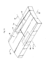
- the device according to the invention comprises two rigid plates 10 formed of rigid composite material, and each having an end edge facing the other plate 10, the end edges in view of the two plates being connected by a softer portion 11 of flexible composite material forming a hinge between the two plates 10 and connecting them.
- the edges facing the plates 10 are plane faces parallel to each other.
- the invention applies equally well to form a flexible hinge between two rigid parts having ends facing one another of different shapes, more or less complex, and the shapes and dimensions of the flexible portion that the connecting must be adapted to allow forming a flexible hinge, particularly in particular to allow pivoting in bending about a theoretical pivot axis interposed between the two ends of the rigid parts.
- the ends of the plates 10 connected by the flexible portion 11 must be spaced from each other by a distance sufficient to allow the passage of said theoretical axis of pivoting, so as to allow the bending of the soft portion 11. This is especially true if these opposite ends are tormented forms.
- each wafer 10 comprises a reinforcing structure 12 which, in the example shown, comprises a plurality of layers parallel to each other and to the main plane of the wafer, spaced from each other and embedded in a matrix 14. These are for example layers of synthetic fibers, including carbon fibers, woven or non-woven or simply deposited in parallel bundles, plies or adjacent strips, pre-impregnated or not.
- the reinforcing structure 12 comprises in any case at least one series of fibers or other tensile members extending longitudinally continuously and uninterruptedly between the two plates 10 and in the flexible portion 11.
- each of the layers of the reinforcing structure 12 of each wafer 10 is extended within the flexible portion 11 and thus constitutes a bonding layer 13 between the two wafers 10, the reinforcing structure 12 also forming the reinforcing reinforcement of the flexible portion 11.
- the reinforcing reinforcement of the flexible composite material constituting the flexible portion 11 consists solely of the reinforcing structure 12.
- the reinforcement 12, composite materials respectively constituting the two rigid plates 10 and the flexible portion 11 allows to connect the two plates 10 together, and allows to connect the flexible portion 11 to each of the two plates 10, which ensures reliably and simply the tensile strength of the hinge thus formed, and facilitates and accelerates its manufacture.
- the reinforcement being common between the plates 10 and the flexible portion 11, all of these different portions can be manufactured simultaneously.
- the rigid composite material forming the wafers 10 (which may be the same for the two wafers 10 or on the contrary different from one wafer to the other) is different from the flexible composite material forming the flexible portion 11, and these materials Rigid (s) and flexible composites differ by matrix at wherein the reinforcement 12, 13 extends.
- the matrix 14 of each rigid composite material constituting a wafer 10 is more rigid than the matrix 19 of the flexible composite material constituting the flexible portion 11.
- the matrix 19 of the flexible composite material is also chosen so as to give the flexible portion 11 the properties flexural flexibility sought.
- the matrix 14 of the rigid composite material is in turn chosen according to the mechanical properties required for the wafers 10, according to their application.
- these two matrices 14, 19 are chosen so as to be compatible with each other, at least during the manufacture of the device according to the invention.
- the two matrices 14, 19 belong to the same chemical family so that they can be implemented by similar manufacturing processes.
- the matrix 14 of each rigid composite material is chosen from thermoplastic polymers: polyethylenes, polystyrenes, polyether ketones; or thermosetting: polyester resins, epoxy resins, phenolic resins, polyimide resins, cyanate ester resins and melamine resins; and the matrix 19 of the flexible composite material is chosen from natural rubbers, silicone elastomers, polyurethane elastomers, polychloroprene elastomers, polyethylenes, polystyrenes, resins, resins charged with magnetic particles, synthetic foams.
- thermoplastic polymers polyethylenes, polystyrenes, polyether ketones
- thermosetting polyester resins, epoxy resins, phenolic resins, polyimide resins, cyanate ester resins and melamine resins
- the matrix 19 of the flexible composite material is chosen from natural rubbers, silicone elastomers, polyurethane elastomers, polychloroprene elastomers, polyethylenes, polysty
- the plates 10 and the flexible portion 11 are formed with the same thickness, and with the same width.
- the flexible portion 11 extends in width over the entire width of the wafers 10, the two wafers 10 themselves having the same width.
- the thickness of the device on the invention is substantially constant in the deployed state.
- the mechanical characteristics of the reinforcement 12, 13 and the matrix 19 of the flexible composite material are chosen so as to allow the hinge thus formed to function, that is to say by allowing a flexion which, for example, is 180.degree. °.
- the second embodiment differs from the first on the one hand in that the plates 10 are bent both in the same direction around a longitudinal axis 23 substantially orthogonal to the theoretical pivot axis 22 of the hinge formed between them, so as to form a type device called "carpentier joint", and, secondly, by the fact that the hinge is formed not of a single flexible portion, but of a plurality of lateral flexible portions separated from each other -especially, in the example shown, two end flexible portions 11a, 11b separated end one the other- by a median portion 15 where the two plates 10 are extended towards each other so as to have side edges 16 which extend transversely and are opposite one another in the deployed state (in which the plates 10 and the flexible portions 11a, 11b are in longitudinal extension of each other, the hinge being unfolded as shown in FIGS. Figures 1a and 1b ).
- the slight bending of the plates 10 and the flexible portions 11a, 11b is visible figure 1c and 1d .
- the invention thus makes it possible to obtain a hinge which is flexible around the longitudinal axis 23 of the plates 10, that is to say in a plane of bending containing the theoretical axis of pivoting 22 and not passing through the platelets 10 (perpendicular to the longitudinal axis 23 of the wafers 10 when this longitudinal axis 23 exists), and is therefore compatible with this transverse flexibility of the wafers 10.
- the device according to the invention therefore allows for a simple, reliable, and compatible with a space environment, a structure with spontaneous elastic deployment of type "carpentier joint".
- the device according to the invention has a small footprint, in particular with a small radius of curvature of the flexible portion in the folded state and a folding angle which can be small (up to 0 °) .
- the invention also makes it possible to control and minimize the bending stresses of the hinge thus formed.
- a device according to the invention makes it possible to transmit torsional forces in the folded state of the hinge, about an axis at least substantially orthogonal to the plane of the plates 10. This torsional stiffness in the folded state makes it possible to stabilize the device, in particular at the launch of a space system in which it is incorporated (for example solar panels folded accordion).
- the two flexible portions 11a, 11b of lateral ends are made of a flexible composite material which is also suitable for their allow to undergo not only the bending deformation corresponding to the folding and unfolding of the hinge, but also a slight bending deformation of the theoretical axis of pivoting of the hinge, imposed by the slightly curved shape of the plates 10, during bending of the hinge thus formed.
- the plurality of flexible portions 11a, 11b interposed between the two plates 10 facilitates this slight deformation.
- the extensions of the wafers 10 in the middle portion 15 between the flexible portions 11a, 11b forming end edges 16 are normally separated by a slot 17 of small width when the device is in the deployed state.
- the end edges 16 act as longitudinal axial stop allowing in particular the device according to the invention to withstand the possible longitudinal compressive stresses and orthogonal torsion moments of the wafers, and to transmit such constraints.
- the edges 16 are, however, adapted to allow the pivoting of the hinge by bending the flexible portions 11a and 11b. To do this, as shown figure 1b they have, for example, rounded edges 24 on the side of the desired direction of rotation.
- this second embodiment can itself be subject to many variations with regard to the number and arrangement of the flexible portions. For example, it is possible to provide a single median flexible portion interposed between two lateral extensions of the rigid portions.
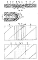
- the third embodiment shown on the Figures 2a to 2d differs from the first embodiment in that the flexible portion 11 forming hinge between the two plates 10 does not extend over the entire thickness of the plates 10 but only over a portion of this thickness, from one of the main faces of the plates 10.
- the flexible portion 11 forming hinge between the two plates 10 does not extend over the entire thickness of the plates 10 but only over a portion of this thickness, from one of the main faces of the plates 10.
- the latter are extended so as to also form end edges extending transversely and facing each other in the deployed state so as to act as longitudinal compression abutment.
- the edges 20 extend along the entire width of the plates 10 and also block the device according to the invention in the deployed state by prohibiting the folding of the hinge in one direction, while allowing the folding of the hinge only in the other meaning as represented figure 2b .
- the device In the deployed state, the device still has a substantially constant thickness between the two plates 10 and at the hinge thus formed.
- the layers forming the reinforcing structure 12 of the rigid plates 10 is extended in the flexible portion 11 and between the two plates 10 so as to act as bonding layers between these different portions 10, 11.
- the layers of the reinforcing structure 12 in the thickness portion corresponding to the end edges 20 are on the contrary interrupted, the matrix 14 of the plates 10 is extended to each of the end edges 20.
- the matrix 19 of the flexible composite material constituting the flexible portion 11 extends only over a portion of the thickness facing the plates 10.
- the fourth embodiment shown on the Figures 3a to 3d is not part of the invention and differs from the third embodiment in that the extensions forming the edges 20 opposite the deployed state are replaced by a plurality of shims 18 superimposed on the flexible portion 11 and glued to this last to complete the thickness between the plates 10, the different shims 18 adjoining each other so as to act as abutment in longitudinal compression in the deployed state ( Figures 3a and 3c ).
- the shims 18 extend according to the width of the wafers 10 parallel to one another and also make it possible to block the device according to the invention in the deployed state by preventing the folding of the hinge in one direction, and by allowing the folding of the hinge only in the other direction as shown on the figure 3b .
- the shims 18 can be made of any material rigid in compression, for example in the same material as the matrix 14 of the rigid composite material constituting at least one of the wafers 10.
- the invention can be the subject of many different embodiments with respect to the various embodiments shown in the figures and described above solely by way of examples, which can be combined in whole or in part.
- reinforcing structures and / or reinforcement reinforcements heterogeneous that is to say formed of several layers or other different elements, for example one or more layer (s) of woven fibers, a or several multilayer (s) metal (s), one or more ply (s) of fibers ...
- the matrices forming the composite materials may be heterogeneous within the thickness and / or the width of rigid and flexible portions.
- each flexible hinge portion may have specific additional reinforcement elements that are specific to it, in addition to each bonding layer formed by a layer of the reinforcement structure of the rigid portions connected by this flexible portion.
- the thickness of each rigid portion and that of each flexible portion is not necessarily the same, and all conceivable embodiments are possible.
- the two rigid portions to be joined are not necessarily strictly identical but may on the contrary be different both in their shapes and in their dimensions ...
- the plates 10 can be bent (tiled) in the same direction (or in the opposite direction) around a substantially orthogonal longitudinal axis to the theoretical pivot axis of the hinge, as in the second embodiment described above.
- the ends of the plates connected by each flexible portion are not necessarily plane songs parallel to each other as in the embodiments shown, but may have different shapes, more tormented.
- the two ends of the plates connected by each flexible portion are not necessarily of the same shape or strictly the same dimensions.
- the two opposite ends of the plates connected by each flexible portion must however be spaced from each other by a distance sufficient to allow the flexion of each flexible portion.
- the invention can also be the subject of many different applications to achieve a reliable flexible hinge without friction at a lower cost.
- a device according to the invention is advantageously applicable to achieve a foldable (deployable) or collapsible (retractable) structure on a space system, for example a deployable mast after launch.
Landscapes
- Engineering & Computer Science (AREA)
- Remote Sensing (AREA)
- Aviation & Aerospace Engineering (AREA)
- Mechanical Engineering (AREA)
- Laminated Bodies (AREA)
- Hinges (AREA)
- Casings For Electric Apparatus (AREA)
- Structure Of Printed Boards (AREA)
- Electric Cable Arrangement Between Relatively Moving Parts (AREA)
Claims (13)
- Vorrichtung, umfassend mindestens einen flexiblen Abschnitt (11), der zwischen zwei Abschnitten integriert ist, genannt starre Abschnitte (10), starrer als jeder flexible Abschnitt (11), wobei jeder starre Abschnitt (10) aus Verbundmaterial gebildet ist, genannt starres Verbundmaterial, wobei der flexible Abschnitt (11) die starren Abschnitte (10) verbindet und ausgelegt ist, um zwischen ihnen ein flexibles Scharnier zu bilden, wobei jeder starre Abschnitt (10) mindestens eine Verstärkungsstruktur (12) eines starren Verbundmaterials, aus dem er besteht, umfasst, dazu ausgelegt, um diesem starren Verbundmaterial eine Widerstandskraft mindestens bei der längs gerichteten Traktion zu verleihen, und eine Matrix (14), innerhalb der sich die Verstärkungsstruktur (12) erstreckt, wobei jeder flexible Abschnitt (11) aus Folgendem gebildet ist:- mindestens einem Material, genannt flexibles Material, ausgewählt aus der Gruppe, bestehend aus Materialien, genannt flexible Verbundmaterialien, umfassend:- eine Verstärkungseinlage, umfassend mindestens eine Schicht, genannt Verbindungsschicht (13), einer Verstärkungsstruktur, die dem/den starren Verbundmaterial(ien) gemeinsam ist, die jeden starren Abschnitt (10) bilden, wobei sich jede Verbindungsschicht (13) anschließend und gemeinsam zwischen den starren Abschnitten (10) erstreckt und ausgelegt ist, um flexibel sein zu können, und- eine Matrix, innerhalb der sich die Verstärkungsstruktur erstreckt, wobei diese Matrix (19) selbst aus einem flexibleren Material als demjenigen gebildet ist, das eine Matrix (14) aus starrem Verbundmaterial jedes starren Abschnitts (10) bildet,- mindestens eine Verbindungsschicht (13) einer Verstärkungsstruktur, die dem/den starren Verbundmaterial(ien) gemeinsam ist, die jeden starren Abschnitt (10) bilden, wobei sich jede Verbindungsschicht (13) anschließend und gemeinsam zwischen den starren Abschnitten (10) erstreckt und ausgelegt ist, um flexibel sein zu können, dadurch gekennzeichnet, dass- sie Kanten (16, 20) gegenüber dem geöffneten Zustand aufweist, in dem die starren Abschnitte (10) und jeder flexible Abschnitt (11) aneinander verlängern, wobei die einander gegenüber liegenden Kanten (16, 20) im geöffneten Zustand angeordnet sind, um bei einem längs gerichtetem Zusammendrücken als Anschlag dienen zu können, und gleichzeitig ein Zusammenklappen des so gebildeten Scharniers mindestens in eine Richtung ausgehend vom geöffneten Zustand zu ermöglichen,- mindesten ein flexibler Abschnitt (11) sich nur auf einem Teil der Dicke und/oder der Verbindungsbreite der starren Abschnitte (10) erstreckt, und dadurch, dass die starren Abschnitte (10) zueinander verlängert sind, gemäß mindestens einem weiteren Teil dieser Dicke und/oder dieser Verbindungsbreite, um die einander gegenüber liegenden Kanten (16, 20) im offenen Zustand aufzuweisen.- die Kannten (16, 20) Stirnseiten aufweisen, die miteinander in Kontakt kommen und dazu ausgelegt sind, Anschläge zu bilden, die ermöglichen, längs gerichtete Zusammendrück- und/oder Torsionskräfte über das auseinander geklappte Scharnier auszuüben und/oder in einer Richtung die Winkelamplitude der Öffnung des so gebildeten Scharniers begrenzen.
- Vorrichtung nach Anspruch 1, dadurch gekennzeichnet, dass mindestens eine Verbindungsschicht (13) mindestens ein Element aufweist, das in der Traktion widerstandsfähig ist, das sich in der Länge kontinuierlich und auf ununterbrochene Weise und innerhalb der starren (10) Abschnitte und jedes flexiblen Abschnitts (11) erstreckt.
- Vorrichtung nach einem der Ansprüche 1 oder 2, dadurch gekennzeichnet, dass das Element ausgewählt ist aus der Gruppe, bestehend aus Monodrähten, Kabeln, Bündeln, Geweben, Nicht-Geweben, Streifen, Matten, Polstern, Blättern und vielschichtigen Komplexen.
- Vorrichtung nach einem der Ansprüche 1 bis 3, dadurch gekennzeichnet, dass jede Verbindungsschicht (13) ausgewählt ist aus der Gruppe bestehend aus Matten aus gewebten synthetischen Fasern, Matten aus nicht gewebten synthetischen Fasern, Polstern, Matten aus gewebten synthetischen Streifen, Matten aus nicht gewebten synthetischen Streifen, Blättern aus synthetischen Materialien, Blättern aus metallischen Materialien, vielschichtigen Komplexen, umfassend mehrere Schichten, wobei jede Schicht aus einem dieser Materialien besteht.
- Vorrichtung nach einem der Ansprüche 1 bis 4, dadurch gekennzeichnet, dass sich jede Schicht der Verstärkungsstruktur (12) des starren Verbundmaterials, das die starren Abschnitte (10) bildet, kontinuierlich zwischen den starren Abschnitten (10) derart erstreckt, dass es eine Verbindungsschicht bildet.
- Vorrichtung nach einem der Ansprüche 1 bis 5, dadurch gekennzeichnet, dass die starren Abschnitte (10) und jeder flexible Abschnitt (11) ähnliche Dicken aufweisen.
- Vorrichtung nach einem der Ansprüche 1 bis 6, dadurch gekennzeichnet, dass sich nur ein Teil der Verstärkungsstruktur (12) der starren Abschnitte (10) kontinuierlich zwischen den starren Abschnitten (10) derart erstreckt, dass er als Verbindungsschicht(en) dient, wobei der andere Teil der Verstärkungsstruktur (12) der starren Abschnitte (10) zwischen den zwei starren Abschnitten (10) unterbrochen ist.
- Vorrichtung nach einem der Ansprüche 1 bis 7, dadurch gekennzeichnet, dass die Verstärkungseinlage des flexiblen Materials nur aus mindestens einer Verbindungsschicht (13) besteht.
- Vorrichtung nach einem der Ansprüche 1 bis 8, dadurch gekennzeichnet, dass die Matrix (19) des flexiblen Verbundmaterials aus einem Material gebildet ist, ausgewählt aus der Gruppe, bestehend aus Naturkautschuk (NR), Elastomeren, Polyethylenharzen, Polystyrenharzen; Polyethylenschäumen; Polystyrenschäumen; Polyurethanschäumen.
- Vorrichtung nach einem der Ansprüche 1 bis 9, dadurch gekennzeichnet, dass sie einen flexiblen Abschnitt (11) umfasst, der sich kontinuierlich auf der gesamten Verbindungsbreite der starren Abschnitte (10) erstreckt.
- Vorrichtung nach einem der Ansprüche 1 bis 10, dadurch gekennzeichnet, dass sie mehrere verschiedene und voneinander getrennte flexible Abschnitte (11) umfasst, die auf der Verbindungsbreite zwischen den starren Abschnitten (10) verteilt sind.
- Vorrichtung nach einem der Ansprüche 1 bis 11, dadurch gekennzeichnet, dass sie Beläge umfasst, die auf jedem starren Abschnitt überhöht aufgesetzt sind, wobei die Beläge derart angeordnet sind, dass sie Kanten aufweisen, die miteinander in Kontakt kommen und ausgelegt sind, um Anschläge zu bilden, die ermöglichen, längs gerichtete Zusammendrück- und/oder Torsionskräfte über das auseinander geklappte Scharnier auszuüben und/oder in einer Richtung die Winkelamplitude der Öffnung des so gebildeten Scharniers zu begrenzen.
- Vorrichtung nach einem der Ansprüche 1 bis 12, dadurch gekennzeichnet, dass jeder starre Abschnitt (10) die allgemeine Form einer Streifenfeder aufweist, die gemäß einer Längsachse gebogen ist, und jeder flexible Abschnitt (11) auch die allgemeine Form eines Streifens aufweist, der gemäß der gleichen Achse gebogen ist.
Applications Claiming Priority (2)
| Application Number | Priority Date | Filing Date | Title |
|---|---|---|---|
| FR0805302A FR2936551B1 (fr) | 2008-09-26 | 2008-09-26 | Dispositif comportant au moins une charniere integree en materiau composite a renfort de liaison ininterrompu. |
| PCT/FR2009/051817 WO2010034946A1 (fr) | 2008-09-26 | 2009-09-24 | Dispositif comportant au moins une charnière intégrée en matériau composite à renfort de liaison ininterrompu |
Publications (2)
| Publication Number | Publication Date |
|---|---|
| EP2340344A1 EP2340344A1 (de) | 2011-07-06 |
| EP2340344B1 true EP2340344B1 (de) | 2014-06-18 |
Family
ID=40532648
Family Applications (1)
| Application Number | Title | Priority Date | Filing Date |
|---|---|---|---|
| EP09752409.4A Active EP2340344B1 (de) | 2008-09-26 | 2009-09-24 | Vorrichtung mit wenigstens einem integrierten scharnier aus verbundmaterial mit einer ununterbrochenen verbundverstärkung |
Country Status (5)
| Country | Link |
|---|---|
| US (1) | US8999474B2 (de) |
| EP (1) | EP2340344B1 (de) |
| ES (1) | ES2498092T3 (de) |
| FR (1) | FR2936551B1 (de) |
| WO (1) | WO2010034946A1 (de) |
Families Citing this family (31)
| Publication number | Priority date | Publication date | Assignee | Title |
|---|---|---|---|---|
| US9551499B1 (en) * | 2006-10-20 | 2017-01-24 | Omni Containment Systems, Llc | Hinge assembly for supporting a fan on a roof |
| DE102010017822A1 (de) * | 2010-04-20 | 2011-10-20 | Airbus Operations Gmbh | Flugzeuginnenausstattungsbauteil und Flugzeuginnenausstattungsbauteilsystem |
| KR101834468B1 (ko) * | 2010-05-18 | 2018-03-05 | 아리아 엔터프라이시스, 인크. | 휴대용 컴팩트 접이식 가구 부품들 |
| CN107741823B (zh) | 2010-05-21 | 2021-11-26 | 诺基亚技术有限公司 | 用于控制设备的显示器输出的方法、设备和计算机程序 |
| EP2511323A1 (de) * | 2011-04-12 | 2012-10-17 | Södra Skogsägarna Ekonomiska Förening | Verbundwerkstoff und Verfahren zur Herstellung eines solchen Verbundwerkstoffs |
| US9823707B2 (en) | 2012-01-25 | 2017-11-21 | Nokia Technologies Oy | Contortion of an electronic apparatus |
| ITMI20120604A1 (it) * | 2012-04-13 | 2013-10-14 | Automobili Lamborghini Spa | Cerniera in materiale composito e processo per la sua fabbricazione |
| US9823696B2 (en) * | 2012-04-27 | 2017-11-21 | Nokia Technologies Oy | Limiting movement |
| US9205629B2 (en) | 2013-03-15 | 2015-12-08 | Ann Livingston-Peters | Composite structure with a flexible section forming a hinge |
| US10544610B2 (en) * | 2013-08-06 | 2020-01-28 | Lockheed Martin Corporation | Composite live hinge |
| EP3052290A1 (de) * | 2013-10-02 | 2016-08-10 | Colin Leslie Hearl Wood | Formen von verstärkten produkten |
| DE202014103159U1 (de) * | 2014-07-09 | 2014-09-29 | Christian Stroetmann | Gerätegehäuse, das eine Befestigungsmöglichkeit für eine flexible beziehungsweise biegbare Anzeige und mindestens zwei Gehäuseteile hat, die durch ein Gelenk/Scharnier verbunden sind |
| EP3153404B1 (de) | 2015-10-06 | 2020-09-23 | Safran Landing Systems UK Limited | Flugzeugbaugruppe |
| EP3426873A1 (de) * | 2016-03-11 | 2019-01-16 | Masonite Corporation | Vorrichtung und verfahren zur montage von türrahmen |
| FR3049636B1 (fr) | 2016-03-30 | 2020-06-26 | Centre National D'etudes Spatiales C N E S | Dispositif comprenant une charniere flexible et des saillies d'extremite de blocage en cisaillement transverse |
| US9869114B1 (en) | 2016-08-05 | 2018-01-16 | Shin Zu Shing Co., Ltd. | Hinge assembly for electronic device |
| CA3083669C (en) | 2016-10-28 | 2023-10-24 | Agri-Cover, Inc. | Folding tonneau cover apparatus |
| US11292324B2 (en) | 2017-10-26 | 2022-04-05 | Agh-Cover, Inc. | Folding tonneau cover having secured flexible hinge |
| US11642948B2 (en) | 2016-10-28 | 2023-05-09 | Agri-Cover, Inc. | Tonneau cover having secured flexible hinge |
| FR3058700B1 (fr) * | 2016-11-17 | 2019-01-25 | Treves Products, Services & Innovation | Faux-plancher de compartiment a bagages de vehicule automobile |
| US10501969B2 (en) * | 2017-02-23 | 2019-12-10 | Unhinged Solutions Llc | Encapsulated flexible hinges |
| US10240374B2 (en) * | 2017-03-29 | 2019-03-26 | Hewlett Packard Enterprise Development Lp | Flexible living hinge for an identification pull tab |
| FR3067379B1 (fr) * | 2017-06-08 | 2019-07-26 | Centre National D'etudes Spatiales C N E S | Dispositif pliable/deployable a repliement spontane comprenant au moins une charniere reliant deux panneaux |
| FR3067378B1 (fr) * | 2017-06-08 | 2019-08-02 | Centre National D'etudes Spatiales C N E S | Dispositif comprenant une charniere flexible et des portions laterales |
| US10322656B2 (en) * | 2017-07-28 | 2019-06-18 | GM Global Technology Operations LLC | Folding furniture piece system and method |
| FR3077270B1 (fr) | 2018-01-29 | 2023-04-07 | Centre Nat Etd Spatiales | Dispositif pliable/deployable comprenant au moins quatre secteurs gauches relies par des charnieres |
| CN108511501B (zh) * | 2018-05-09 | 2021-01-22 | 京东方科技集团股份有限公司 | 可弯折的盖板、oled显示装置及其制造方法 |
| CN113745353B (zh) * | 2021-08-25 | 2025-06-10 | 隆基乐叶光伏科技有限公司 | 一种封装盖板及其制作方法、光伏组件 |
| CN114248475B (zh) * | 2021-12-20 | 2023-09-22 | 浙江万丰飞机制造有限公司 | 一种复合材料u形铰链的制作方法 |
| CN114311871B (zh) * | 2022-01-18 | 2023-02-28 | 天津大学 | 可折型frp板及其制作方法 |
| FR3137013B1 (fr) * | 2022-06-22 | 2025-05-23 | Safran Landing Systems | Procédé de fabrication d’une pièce en matériau composite destinée à être articulée avec d’autres pièces |
Family Cites Families (12)
| Publication number | Priority date | Publication date | Assignee | Title |
|---|---|---|---|---|
| FR1382678A (fr) * | 1964-02-14 | 1964-12-18 | Van Tam Nguyen | Charnière monobloc |
| US4387128A (en) * | 1979-07-12 | 1983-06-07 | Brymitre Limited | Foldable structure |
| US4476174A (en) * | 1981-10-02 | 1984-10-09 | Tenex Corporation | Composite plastic mat and method of forming same |
| US4438605A (en) * | 1981-10-19 | 1984-03-27 | Delucia Paul V | Continuous, moveable thermal barrier system |
| US4463046A (en) * | 1983-10-11 | 1984-07-31 | Crane Plastics, Inc. | Synthetic resin panels joined by an integral hinge having dual durometer plies |
| US5350614A (en) * | 1991-07-25 | 1994-09-27 | United Technologies Corporation | All composite article of manufacture including first and second composite members joined by a composite hinge |
| DE4224699A1 (de) | 1992-07-25 | 1994-01-27 | Euwe Eugen Wexler Gmbh | Kunststoffgelenk zur gelenkigen Verbindung zweier Bauteile |
| JP3451041B2 (ja) * | 1999-09-17 | 2003-09-29 | 川崎重工業株式会社 | フラップヒンジ機構およびその製造方法ならびにフラップヒンジ装置 |
| CA2339332A1 (en) * | 2000-03-09 | 2001-09-09 | Andersen Corporation | Hinged thermoplastic-fabric reinforced structural member, profile and methods therefore |
| EP1738895B1 (de) * | 2005-06-29 | 2012-07-18 | SGL Carbon SE | Gelenk |
| US7354033B1 (en) * | 2006-08-01 | 2008-04-08 | The United States Of America As Represented By The Secretary Of The Air Force | Tape-spring deployable hinge |
| FR2908366A1 (fr) | 2006-11-15 | 2008-05-16 | Cera | Tablette de recouvrement d'un compartiment a bagages de vehicule automobile comprenant deux panneaux associes par un ressort a lame |
-
2008
- 2008-09-26 FR FR0805302A patent/FR2936551B1/fr not_active Expired - Fee Related
-
2009
- 2009-09-24 WO PCT/FR2009/051817 patent/WO2010034946A1/fr not_active Ceased
- 2009-09-24 US US13/120,979 patent/US8999474B2/en active Active
- 2009-09-24 ES ES09752409.4T patent/ES2498092T3/es active Active
- 2009-09-24 EP EP09752409.4A patent/EP2340344B1/de active Active
Also Published As
| Publication number | Publication date |
|---|---|
| US20110177279A1 (en) | 2011-07-21 |
| ES2498092T3 (es) | 2014-09-24 |
| FR2936551B1 (fr) | 2014-01-17 |
| US8999474B2 (en) | 2015-04-07 |
| FR2936551A1 (fr) | 2010-04-02 |
| EP2340344A1 (de) | 2011-07-06 |
| WO2010034946A1 (fr) | 2010-04-01 |
Similar Documents
| Publication | Publication Date | Title |
|---|---|---|
| WO2010034946A1 (fr) | Dispositif comportant au moins une charnière intégrée en matériau composite à renfort de liaison ininterrompu | |
| EP2328804B1 (de) | Rumpfstruktur für die kombinierte befestigung einer isoliermatte und von vorrichtungen sowie luftfahrzeug mit solch einer struktur | |
| EP2802803A1 (de) | Hochleistungsfähige dünne wärmedämmvorrichtung | |
| WO2008145892A1 (fr) | Dispositif de fixation d'un organe de sustentation au fuselage d'un avion | |
| EP3003705A1 (de) | Verbundplatte für böden oder wandverkleidungskomponenten und verfahren zur herstellung solch einer platte | |
| FR3078048A1 (fr) | Dispositif de protection de batterie en cas de choc lateral et vehicule equipe d’un tel dispositif | |
| FR2775926A1 (fr) | Procede de fabrication d'une charniere en tissu, stratifiee a chaud et charniere obtenue par ce procede | |
| FR2920042A1 (fr) | Composant structurel absorbant les impulsions | |
| EP3326920A1 (de) | Entfaltbare struktur mit spontaner entfaltung | |
| FR2780460A1 (fr) | Arbre de transmission de puissance | |
| FR3067073B1 (fr) | Connecteur avec rotule integree | |
| CA2994042A1 (fr) | Siege deformable pour vehicule | |
| EP1788646B1 (de) | Planarer Aktor mit Sandwich-Aufbau und Anwendung zur Torsion einer Struktur | |
| EP2622232B1 (de) | Geriffelter haltewinkel aus einem verbundstoff | |
| FR3049636A1 (fr) | Dispositif comprenant une charniere flexible et des saillies d'extremite de blocage en cisaillement transverse | |
| EP2459404B1 (de) | Gelenkglastafel mit kammförmigem einsatz sowie verfahren zur herstellung dieser glastafel | |
| FR3067378B1 (fr) | Dispositif comprenant une charniere flexible et des portions laterales | |
| WO2019145663A1 (fr) | Dispositif pliable/déployable comprenant au moins quatre secteurs gauches reliés par des charnières | |
| FR3054009A1 (fr) | Accessoire pour ensemble formant raccord avec systeme anti-perforation | |
| FR3067379B1 (fr) | Dispositif pliable/deployable a repliement spontane comprenant au moins une charniere reliant deux panneaux | |
| WO2007048899A1 (fr) | Structure stratifiee sandwich perfectionnee | |
| FR2928778A1 (fr) | Materiau composite souple ou rigide absorbant les ondes electromagnetiques. | |
| FR2967607A1 (fr) | Ame pour structure de type sandwich, structure de type sandwich comprenant une telle ame, procede de fabrication d’une telle ame | |
| WO2006129004A2 (fr) | Cale expansible et systeme comprenant un module, un receptacle et une telle cale intercalee entre eux. | |
| EP1365055A1 (de) | Als Sperrschicht dienendes verstärktes Fasermaterial für die Herstellung von Verbundwerkteilen |
Legal Events
| Date | Code | Title | Description |
|---|---|---|---|
| PUAI | Public reference made under article 153(3) epc to a published international application that has entered the european phase |
Free format text: ORIGINAL CODE: 0009012 |
|
| 17P | Request for examination filed |
Effective date: 20110422 |
|
| AK | Designated contracting states |
Kind code of ref document: A1 Designated state(s): AT BE BG CH CY CZ DE DK EE ES FI FR GB GR HR HU IE IS IT LI LT LU LV MC MK MT NL NO PL PT RO SE SI SK SM TR |
|
| AX | Request for extension of the european patent |
Extension state: AL BA RS |
|
| DAX | Request for extension of the european patent (deleted) | ||
| 17Q | First examination report despatched |
Effective date: 20121011 |
|
| GRAP | Despatch of communication of intention to grant a patent |
Free format text: ORIGINAL CODE: EPIDOSNIGR1 |
|
| INTG | Intention to grant announced |
Effective date: 20140114 |
|
| GRAS | Grant fee paid |
Free format text: ORIGINAL CODE: EPIDOSNIGR3 |
|
| GRAA | (expected) grant |
Free format text: ORIGINAL CODE: 0009210 |
|
| AK | Designated contracting states |
Kind code of ref document: B1 Designated state(s): AT BE BG CH CY CZ DE DK EE ES FI FR GB GR HR HU IE IS IT LI LT LU LV MC MK MT NL NO PL PT RO SE SI SK SM TR |
|
| RAP1 | Party data changed (applicant data changed or rights of an application transferred) |
Owner name: CENTRE NATIONAL D'ETUDES SPATIALES (CNES) |
|
| REG | Reference to a national code |
Ref country code: GB Ref legal event code: FG4D Free format text: NOT ENGLISH |
|
| REG | Reference to a national code |
Ref country code: CH Ref legal event code: EP |
|
| REG | Reference to a national code |
Ref country code: AT Ref legal event code: REF Ref document number: 673463 Country of ref document: AT Kind code of ref document: T Effective date: 20140715 |
|
| REG | Reference to a national code |
Ref country code: IE Ref legal event code: FG4D Free format text: LANGUAGE OF EP DOCUMENT: FRENCH |
|
| REG | Reference to a national code |
Ref country code: DE Ref legal event code: R096 Ref document number: 602009024770 Country of ref document: DE Effective date: 20140731 |
|
| REG | Reference to a national code |
Ref country code: CH Ref legal event code: NV Representative=s name: LEMAN CONSULTING S.A., CH |
|
| REG | Reference to a national code |
Ref country code: ES Ref legal event code: FG2A Ref document number: 2498092 Country of ref document: ES Kind code of ref document: T3 Effective date: 20140924 |
|
| PG25 | Lapsed in a contracting state [announced via postgrant information from national office to epo] |
Ref country code: CY Free format text: LAPSE BECAUSE OF FAILURE TO SUBMIT A TRANSLATION OF THE DESCRIPTION OR TO PAY THE FEE WITHIN THE PRESCRIBED TIME-LIMIT Effective date: 20140618 Ref country code: NO Free format text: LAPSE BECAUSE OF FAILURE TO SUBMIT A TRANSLATION OF THE DESCRIPTION OR TO PAY THE FEE WITHIN THE PRESCRIBED TIME-LIMIT Effective date: 20140918 Ref country code: LT Free format text: LAPSE BECAUSE OF FAILURE TO SUBMIT A TRANSLATION OF THE DESCRIPTION OR TO PAY THE FEE WITHIN THE PRESCRIBED TIME-LIMIT Effective date: 20140618 Ref country code: GR Free format text: LAPSE BECAUSE OF FAILURE TO SUBMIT A TRANSLATION OF THE DESCRIPTION OR TO PAY THE FEE WITHIN THE PRESCRIBED TIME-LIMIT Effective date: 20140919 Ref country code: FI Free format text: LAPSE BECAUSE OF FAILURE TO SUBMIT A TRANSLATION OF THE DESCRIPTION OR TO PAY THE FEE WITHIN THE PRESCRIBED TIME-LIMIT Effective date: 20140618 |
|
| REG | Reference to a national code |
Ref country code: NL Ref legal event code: T3 |
|
| REG | Reference to a national code |
Ref country code: AT Ref legal event code: MK05 Ref document number: 673463 Country of ref document: AT Kind code of ref document: T Effective date: 20140618 |
|
| REG | Reference to a national code |
Ref country code: LT Ref legal event code: MG4D |
|
| PG25 | Lapsed in a contracting state [announced via postgrant information from national office to epo] |
Ref country code: HR Free format text: LAPSE BECAUSE OF FAILURE TO SUBMIT A TRANSLATION OF THE DESCRIPTION OR TO PAY THE FEE WITHIN THE PRESCRIBED TIME-LIMIT Effective date: 20140618 Ref country code: LV Free format text: LAPSE BECAUSE OF FAILURE TO SUBMIT A TRANSLATION OF THE DESCRIPTION OR TO PAY THE FEE WITHIN THE PRESCRIBED TIME-LIMIT Effective date: 20140618 Ref country code: SE Free format text: LAPSE BECAUSE OF FAILURE TO SUBMIT A TRANSLATION OF THE DESCRIPTION OR TO PAY THE FEE WITHIN THE PRESCRIBED TIME-LIMIT Effective date: 20140618 |
|
| PG25 | Lapsed in a contracting state [announced via postgrant information from national office to epo] |
Ref country code: EE Free format text: LAPSE BECAUSE OF FAILURE TO SUBMIT A TRANSLATION OF THE DESCRIPTION OR TO PAY THE FEE WITHIN THE PRESCRIBED TIME-LIMIT Effective date: 20140618 Ref country code: PT Free format text: LAPSE BECAUSE OF FAILURE TO SUBMIT A TRANSLATION OF THE DESCRIPTION OR TO PAY THE FEE WITHIN THE PRESCRIBED TIME-LIMIT Effective date: 20141020 Ref country code: RO Free format text: LAPSE BECAUSE OF FAILURE TO SUBMIT A TRANSLATION OF THE DESCRIPTION OR TO PAY THE FEE WITHIN THE PRESCRIBED TIME-LIMIT Effective date: 20140618 Ref country code: CZ Free format text: LAPSE BECAUSE OF FAILURE TO SUBMIT A TRANSLATION OF THE DESCRIPTION OR TO PAY THE FEE WITHIN THE PRESCRIBED TIME-LIMIT Effective date: 20140618 Ref country code: SK Free format text: LAPSE BECAUSE OF FAILURE TO SUBMIT A TRANSLATION OF THE DESCRIPTION OR TO PAY THE FEE WITHIN THE PRESCRIBED TIME-LIMIT Effective date: 20140618 |
|
| PG25 | Lapsed in a contracting state [announced via postgrant information from national office to epo] |
Ref country code: AT Free format text: LAPSE BECAUSE OF FAILURE TO SUBMIT A TRANSLATION OF THE DESCRIPTION OR TO PAY THE FEE WITHIN THE PRESCRIBED TIME-LIMIT Effective date: 20140618 Ref country code: IS Free format text: LAPSE BECAUSE OF FAILURE TO SUBMIT A TRANSLATION OF THE DESCRIPTION OR TO PAY THE FEE WITHIN THE PRESCRIBED TIME-LIMIT Effective date: 20141018 Ref country code: PL Free format text: LAPSE BECAUSE OF FAILURE TO SUBMIT A TRANSLATION OF THE DESCRIPTION OR TO PAY THE FEE WITHIN THE PRESCRIBED TIME-LIMIT Effective date: 20140618 |
|
| REG | Reference to a national code |
Ref country code: DE Ref legal event code: R097 Ref document number: 602009024770 Country of ref document: DE |
|
| PLBE | No opposition filed within time limit |
Free format text: ORIGINAL CODE: 0009261 |
|
| STAA | Information on the status of an ep patent application or granted ep patent |
Free format text: STATUS: NO OPPOSITION FILED WITHIN TIME LIMIT |
|
| PG25 | Lapsed in a contracting state [announced via postgrant information from national office to epo] |
Ref country code: DK Free format text: LAPSE BECAUSE OF FAILURE TO SUBMIT A TRANSLATION OF THE DESCRIPTION OR TO PAY THE FEE WITHIN THE PRESCRIBED TIME-LIMIT Effective date: 20140618 Ref country code: MC Free format text: LAPSE BECAUSE OF FAILURE TO SUBMIT A TRANSLATION OF THE DESCRIPTION OR TO PAY THE FEE WITHIN THE PRESCRIBED TIME-LIMIT Effective date: 20140618 |
|
| 26N | No opposition filed |
Effective date: 20150319 |
|
| PG25 | Lapsed in a contracting state [announced via postgrant information from national office to epo] |
Ref country code: SI Free format text: LAPSE BECAUSE OF FAILURE TO SUBMIT A TRANSLATION OF THE DESCRIPTION OR TO PAY THE FEE WITHIN THE PRESCRIBED TIME-LIMIT Effective date: 20140618 |
|
| REG | Reference to a national code |
Ref country code: FR Ref legal event code: PLFP Year of fee payment: 7 |
|
| PG25 | Lapsed in a contracting state [announced via postgrant information from national office to epo] |
Ref country code: SM Free format text: LAPSE BECAUSE OF FAILURE TO SUBMIT A TRANSLATION OF THE DESCRIPTION OR TO PAY THE FEE WITHIN THE PRESCRIBED TIME-LIMIT Effective date: 20140618 |
|
| PG25 | Lapsed in a contracting state [announced via postgrant information from national office to epo] |
Ref country code: BG Free format text: LAPSE BECAUSE OF FAILURE TO SUBMIT A TRANSLATION OF THE DESCRIPTION OR TO PAY THE FEE WITHIN THE PRESCRIBED TIME-LIMIT Effective date: 20140618 Ref country code: MT Free format text: LAPSE BECAUSE OF FAILURE TO SUBMIT A TRANSLATION OF THE DESCRIPTION OR TO PAY THE FEE WITHIN THE PRESCRIBED TIME-LIMIT Effective date: 20140618 |
|
| PG25 | Lapsed in a contracting state [announced via postgrant information from national office to epo] |
Ref country code: HU Free format text: LAPSE BECAUSE OF FAILURE TO SUBMIT A TRANSLATION OF THE DESCRIPTION OR TO PAY THE FEE WITHIN THE PRESCRIBED TIME-LIMIT; INVALID AB INITIO Effective date: 20090924 Ref country code: TR Free format text: LAPSE BECAUSE OF FAILURE TO SUBMIT A TRANSLATION OF THE DESCRIPTION OR TO PAY THE FEE WITHIN THE PRESCRIBED TIME-LIMIT Effective date: 20140618 |
|
| REG | Reference to a national code |
Ref country code: FR Ref legal event code: PLFP Year of fee payment: 8 |
|
| REG | Reference to a national code |
Ref country code: FR Ref legal event code: PLFP Year of fee payment: 9 |
|
| REG | Reference to a national code |
Ref country code: CH Ref legal event code: NV Representative=s name: IP PARTNERS J. WENGER, CH |
|
| PG25 | Lapsed in a contracting state [announced via postgrant information from national office to epo] |
Ref country code: MK Free format text: LAPSE BECAUSE OF FAILURE TO SUBMIT A TRANSLATION OF THE DESCRIPTION OR TO PAY THE FEE WITHIN THE PRESCRIBED TIME-LIMIT Effective date: 20140618 |
|
| REG | Reference to a national code |
Ref country code: FR Ref legal event code: PLFP Year of fee payment: 10 |
|
| PGFP | Annual fee paid to national office [announced via postgrant information from national office to epo] |
Ref country code: NL Payment date: 20230818 Year of fee payment: 15 Ref country code: LU Payment date: 20230822 Year of fee payment: 15 |
|
| PGFP | Annual fee paid to national office [announced via postgrant information from national office to epo] |
Ref country code: IT Payment date: 20230908 Year of fee payment: 15 Ref country code: IE Payment date: 20230817 Year of fee payment: 15 Ref country code: GB Payment date: 20230816 Year of fee payment: 15 |
|
| PGFP | Annual fee paid to national office [announced via postgrant information from national office to epo] |
Ref country code: FR Payment date: 20230816 Year of fee payment: 15 Ref country code: DE Payment date: 20230818 Year of fee payment: 15 Ref country code: BE Payment date: 20230914 Year of fee payment: 15 |
|
| PGFP | Annual fee paid to national office [announced via postgrant information from national office to epo] |
Ref country code: ES Payment date: 20231006 Year of fee payment: 15 |
|
| PGFP | Annual fee paid to national office [announced via postgrant information from national office to epo] |
Ref country code: CH Payment date: 20231001 Year of fee payment: 15 |
|
| REG | Reference to a national code |
Ref country code: DE Ref legal event code: R119 Ref document number: 602009024770 Country of ref document: DE |
|
| REG | Reference to a national code |
Ref country code: CH Ref legal event code: PL |
|
| REG | Reference to a national code |
Ref country code: NL Ref legal event code: MM Effective date: 20241001 |
|
| PG25 | Lapsed in a contracting state [announced via postgrant information from national office to epo] |
Ref country code: LU Free format text: LAPSE BECAUSE OF NON-PAYMENT OF DUE FEES Effective date: 20240924 |
|
| GBPC | Gb: european patent ceased through non-payment of renewal fee |
Effective date: 20240924 |
|
| PG25 | Lapsed in a contracting state [announced via postgrant information from national office to epo] |
Ref country code: NL Free format text: LAPSE BECAUSE OF NON-PAYMENT OF DUE FEES Effective date: 20241001 |
|
| PG25 | Lapsed in a contracting state [announced via postgrant information from national office to epo] |
Ref country code: DE Free format text: LAPSE BECAUSE OF NON-PAYMENT OF DUE FEES Effective date: 20250401 |
|
| PG25 | Lapsed in a contracting state [announced via postgrant information from national office to epo] |
Ref country code: GB Free format text: LAPSE BECAUSE OF NON-PAYMENT OF DUE FEES Effective date: 20240924 |
|
| REG | Reference to a national code |
Ref country code: BE Ref legal event code: MM Effective date: 20240930 |
|
| PG25 | Lapsed in a contracting state [announced via postgrant information from national office to epo] |
Ref country code: IT Free format text: LAPSE BECAUSE OF NON-PAYMENT OF DUE FEES Effective date: 20240924 Ref country code: BE Free format text: LAPSE BECAUSE OF NON-PAYMENT OF DUE FEES Effective date: 20240930 |
|
| PG25 | Lapsed in a contracting state [announced via postgrant information from national office to epo] |
Ref country code: FR Free format text: LAPSE BECAUSE OF NON-PAYMENT OF DUE FEES Effective date: 20240930 |
|
| PG25 | Lapsed in a contracting state [announced via postgrant information from national office to epo] |
Ref country code: CH Free format text: LAPSE BECAUSE OF NON-PAYMENT OF DUE FEES Effective date: 20240930 |
|
| PG25 | Lapsed in a contracting state [announced via postgrant information from national office to epo] |
Ref country code: IE Free format text: LAPSE BECAUSE OF NON-PAYMENT OF DUE FEES Effective date: 20240924 |
|
| REG | Reference to a national code |
Ref country code: ES Ref legal event code: FD2A Effective date: 20251031 |
|
| PG25 | Lapsed in a contracting state [announced via postgrant information from national office to epo] |
Ref country code: ES Free format text: LAPSE BECAUSE OF NON-PAYMENT OF DUE FEES Effective date: 20240925 |