EP2340125B1 - Tête de pulvérisation et dispositif de pulvérisation avec conduit de gaz sous pression - Google Patents
Tête de pulvérisation et dispositif de pulvérisation avec conduit de gaz sous pression Download PDFInfo
- Publication number
- EP2340125B1 EP2340125B1 EP09741185.4A EP09741185A EP2340125B1 EP 2340125 B1 EP2340125 B1 EP 2340125B1 EP 09741185 A EP09741185 A EP 09741185A EP 2340125 B1 EP2340125 B1 EP 2340125B1
- Authority
- EP
- European Patent Office
- Prior art keywords
- spray head
- component
- outlets
- tip
- webs
- Prior art date
- Legal status (The legal status is an assumption and is not a legal conclusion. Google has not performed a legal analysis and makes no representation as to the accuracy of the status listed.)
- Active
Links
- 239000007921 spray Substances 0.000 title claims description 202
- 238000005507 spraying Methods 0.000 title claims description 26
- 239000000126 substance Substances 0.000 claims description 18
- 238000007599 discharging Methods 0.000 claims description 5
- 238000012216 screening Methods 0.000 claims description 2
- 239000000203 mixture Substances 0.000 description 6
- 230000015572 biosynthetic process Effects 0.000 description 4
- 230000002093 peripheral effect Effects 0.000 description 4
- 230000002028 premature Effects 0.000 description 3
- 206010052428 Wound Diseases 0.000 description 2
- 208000027418 Wounds and injury Diseases 0.000 description 2
- 239000000853 adhesive Substances 0.000 description 2
- 230000001070 adhesive effect Effects 0.000 description 2
- 238000000889 atomisation Methods 0.000 description 2
- 230000009977 dual effect Effects 0.000 description 2
- 230000000694 effects Effects 0.000 description 2
- 238000000034 method Methods 0.000 description 2
- 238000004544 sputter deposition Methods 0.000 description 2
- 230000032258 transport Effects 0.000 description 2
- 108090000190 Thrombin Proteins 0.000 description 1
- 230000000740 bleeding effect Effects 0.000 description 1
- 238000004891 communication Methods 0.000 description 1
- 238000005520 cutting process Methods 0.000 description 1
- 230000001419 dependent effect Effects 0.000 description 1
- 238000013461 design Methods 0.000 description 1
- 238000001514 detection method Methods 0.000 description 1
- 238000009826 distribution Methods 0.000 description 1
- 238000005516 engineering process Methods 0.000 description 1
- 239000012530 fluid Substances 0.000 description 1
- 238000003780 insertion Methods 0.000 description 1
- 230000037431 insertion Effects 0.000 description 1
- 238000004519 manufacturing process Methods 0.000 description 1
- 238000007789 sealing Methods 0.000 description 1
- 229960004072 thrombin Drugs 0.000 description 1
Images


Classifications
-
- B—PERFORMING OPERATIONS; TRANSPORTING
- B05—SPRAYING OR ATOMISING IN GENERAL; APPLYING FLUENT MATERIALS TO SURFACES, IN GENERAL
- B05B—SPRAYING APPARATUS; ATOMISING APPARATUS; NOZZLES
- B05B7/00—Spraying apparatus for discharge of liquids or other fluent materials from two or more sources, e.g. of liquid and air, of powder and gas
- B05B7/02—Spray pistols; Apparatus for discharge
- B05B7/08—Spray pistols; Apparatus for discharge with separate outlet orifices, e.g. to form parallel jets, i.e. the axis of the jets being parallel, to form intersecting jets, i.e. the axis of the jets converging but not necessarily intersecting at a point
- B05B7/0807—Spray pistols; Apparatus for discharge with separate outlet orifices, e.g. to form parallel jets, i.e. the axis of the jets being parallel, to form intersecting jets, i.e. the axis of the jets converging but not necessarily intersecting at a point to form intersecting jets
- B05B7/0861—Spray pistols; Apparatus for discharge with separate outlet orifices, e.g. to form parallel jets, i.e. the axis of the jets being parallel, to form intersecting jets, i.e. the axis of the jets converging but not necessarily intersecting at a point to form intersecting jets with one single jet constituted by a liquid or a mixture containing a liquid and several gas jets
-
- A—HUMAN NECESSITIES
- A61—MEDICAL OR VETERINARY SCIENCE; HYGIENE
- A61B—DIAGNOSIS; SURGERY; IDENTIFICATION
- A61B17/00—Surgical instruments, devices or methods, e.g. tourniquets
- A61B17/00491—Surgical glue applicators
-
- B—PERFORMING OPERATIONS; TRANSPORTING
- B01—PHYSICAL OR CHEMICAL PROCESSES OR APPARATUS IN GENERAL
- B01F—MIXING, e.g. DISSOLVING, EMULSIFYING OR DISPERSING
- B01F25/00—Flow mixers; Mixers for falling materials, e.g. solid particles
- B01F25/40—Static mixers
- B01F25/42—Static mixers in which the mixing is affected by moving the components jointly in changing directions, e.g. in tubes provided with baffles or obstructions
- B01F25/43—Mixing tubes, e.g. wherein the material is moved in a radial or partly reversed direction
- B01F25/431—Straight mixing tubes with baffles or obstructions that do not cause substantial pressure drop; Baffles therefor
- B01F25/4314—Straight mixing tubes with baffles or obstructions that do not cause substantial pressure drop; Baffles therefor with helical baffles
- B01F25/43141—Straight mixing tubes with baffles or obstructions that do not cause substantial pressure drop; Baffles therefor with helical baffles composed of consecutive sections of helical formed elements
-
- B—PERFORMING OPERATIONS; TRANSPORTING
- B01—PHYSICAL OR CHEMICAL PROCESSES OR APPARATUS IN GENERAL
- B01F—MIXING, e.g. DISSOLVING, EMULSIFYING OR DISPERSING
- B01F33/00—Other mixers; Mixing plants; Combinations of mixers
- B01F33/40—Mixers using gas or liquid agitation, e.g. with air supply tubes
- B01F33/404—Mixers using gas or liquid agitation, e.g. with air supply tubes for mixing material moving continuously therethrough, e.g. using impinging jets
-
- B—PERFORMING OPERATIONS; TRANSPORTING
- B01—PHYSICAL OR CHEMICAL PROCESSES OR APPARATUS IN GENERAL
- B01F—MIXING, e.g. DISSOLVING, EMULSIFYING OR DISPERSING
- B01F33/00—Other mixers; Mixing plants; Combinations of mixers
- B01F33/50—Movable or transportable mixing devices or plants
- B01F33/501—Movable mixing devices, i.e. readily shifted or displaced from one place to another, e.g. portable during use
- B01F33/5011—Movable mixing devices, i.e. readily shifted or displaced from one place to another, e.g. portable during use portable during use, e.g. hand-held
- B01F33/50112—Movable mixing devices, i.e. readily shifted or displaced from one place to another, e.g. portable during use portable during use, e.g. hand-held of the syringe or cartridge type
-
- B—PERFORMING OPERATIONS; TRANSPORTING
- B05—SPRAYING OR ATOMISING IN GENERAL; APPLYING FLUENT MATERIALS TO SURFACES, IN GENERAL
- B05B—SPRAYING APPARATUS; ATOMISING APPARATUS; NOZZLES
- B05B7/00—Spraying apparatus for discharge of liquids or other fluent materials from two or more sources, e.g. of liquid and air, of powder and gas
- B05B7/02—Spray pistols; Apparatus for discharge
- B05B7/04—Spray pistols; Apparatus for discharge with arrangements for mixing liquids or other fluent materials before discharge
- B05B7/0408—Spray pistols; Apparatus for discharge with arrangements for mixing liquids or other fluent materials before discharge with arrangements for mixing two or more liquids
-
- B—PERFORMING OPERATIONS; TRANSPORTING
- B05—SPRAYING OR ATOMISING IN GENERAL; APPLYING FLUENT MATERIALS TO SURFACES, IN GENERAL
- B05B—SPRAYING APPARATUS; ATOMISING APPARATUS; NOZZLES
- B05B7/00—Spraying apparatus for discharge of liquids or other fluent materials from two or more sources, e.g. of liquid and air, of powder and gas
- B05B7/02—Spray pistols; Apparatus for discharge
- B05B7/08—Spray pistols; Apparatus for discharge with separate outlet orifices, e.g. to form parallel jets, i.e. the axis of the jets being parallel, to form intersecting jets, i.e. the axis of the jets converging but not necessarily intersecting at a point
- B05B7/0807—Spray pistols; Apparatus for discharge with separate outlet orifices, e.g. to form parallel jets, i.e. the axis of the jets being parallel, to form intersecting jets, i.e. the axis of the jets converging but not necessarily intersecting at a point to form intersecting jets
-
- B—PERFORMING OPERATIONS; TRANSPORTING
- B05—SPRAYING OR ATOMISING IN GENERAL; APPLYING FLUENT MATERIALS TO SURFACES, IN GENERAL
- B05B—SPRAYING APPARATUS; ATOMISING APPARATUS; NOZZLES
- B05B7/00—Spraying apparatus for discharge of liquids or other fluent materials from two or more sources, e.g. of liquid and air, of powder and gas
- B05B7/02—Spray pistols; Apparatus for discharge
- B05B7/08—Spray pistols; Apparatus for discharge with separate outlet orifices, e.g. to form parallel jets, i.e. the axis of the jets being parallel, to form intersecting jets, i.e. the axis of the jets converging but not necessarily intersecting at a point
- B05B7/0892—Spray pistols; Apparatus for discharge with separate outlet orifices, e.g. to form parallel jets, i.e. the axis of the jets being parallel, to form intersecting jets, i.e. the axis of the jets converging but not necessarily intersecting at a point the outlet orifices for jets constituted by a liquid or a mixture containing a liquid being disposed on a circle
-
- B—PERFORMING OPERATIONS; TRANSPORTING
- B05—SPRAYING OR ATOMISING IN GENERAL; APPLYING FLUENT MATERIALS TO SURFACES, IN GENERAL
- B05B—SPRAYING APPARATUS; ATOMISING APPARATUS; NOZZLES
- B05B7/00—Spraying apparatus for discharge of liquids or other fluent materials from two or more sources, e.g. of liquid and air, of powder and gas
- B05B7/24—Spraying apparatus for discharge of liquids or other fluent materials from two or more sources, e.g. of liquid and air, of powder and gas with means, e.g. a container, for supplying liquid or other fluent material to a discharge device
- B05B7/2402—Apparatus to be carried on or by a person, e.g. by hand; Apparatus comprising containers fixed to the discharge device
- B05B7/2405—Apparatus to be carried on or by a person, e.g. by hand; Apparatus comprising containers fixed to the discharge device using an atomising fluid as carrying fluid for feeding, e.g. by suction or pressure, a carried liquid from the container to the nozzle
- B05B7/2408—Apparatus to be carried on or by a person, e.g. by hand; Apparatus comprising containers fixed to the discharge device using an atomising fluid as carrying fluid for feeding, e.g. by suction or pressure, a carried liquid from the container to the nozzle characterised by the container or its attachment means to the spray apparatus
-
- B—PERFORMING OPERATIONS; TRANSPORTING
- B05—SPRAYING OR ATOMISING IN GENERAL; APPLYING FLUENT MATERIALS TO SURFACES, IN GENERAL
- B05B—SPRAYING APPARATUS; ATOMISING APPARATUS; NOZZLES
- B05B7/00—Spraying apparatus for discharge of liquids or other fluent materials from two or more sources, e.g. of liquid and air, of powder and gas
- B05B7/24—Spraying apparatus for discharge of liquids or other fluent materials from two or more sources, e.g. of liquid and air, of powder and gas with means, e.g. a container, for supplying liquid or other fluent material to a discharge device
- B05B7/2402—Apparatus to be carried on or by a person, e.g. by hand; Apparatus comprising containers fixed to the discharge device
- B05B7/244—Apparatus to be carried on or by a person, e.g. by hand; Apparatus comprising containers fixed to the discharge device using carrying liquid for feeding, e.g. by suction, pressure or dissolution, a carried liquid from the container to the nozzle
- B05B7/2448—Apparatus to be carried on or by a person, e.g. by hand; Apparatus comprising containers fixed to the discharge device using carrying liquid for feeding, e.g. by suction, pressure or dissolution, a carried liquid from the container to the nozzle the carried liquid and the main stream of carrying liquid being brought together after discharge
-
- B—PERFORMING OPERATIONS; TRANSPORTING
- B05—SPRAYING OR ATOMISING IN GENERAL; APPLYING FLUENT MATERIALS TO SURFACES, IN GENERAL
- B05B—SPRAYING APPARATUS; ATOMISING APPARATUS; NOZZLES
- B05B7/00—Spraying apparatus for discharge of liquids or other fluent materials from two or more sources, e.g. of liquid and air, of powder and gas
- B05B7/24—Spraying apparatus for discharge of liquids or other fluent materials from two or more sources, e.g. of liquid and air, of powder and gas with means, e.g. a container, for supplying liquid or other fluent material to a discharge device
- B05B7/2402—Apparatus to be carried on or by a person, e.g. by hand; Apparatus comprising containers fixed to the discharge device
- B05B7/2472—Apparatus to be carried on or by a person, e.g. by hand; Apparatus comprising containers fixed to the discharge device comprising several containers
-
- A—HUMAN NECESSITIES
- A61—MEDICAL OR VETERINARY SCIENCE; HYGIENE
- A61B—DIAGNOSIS; SURGERY; IDENTIFICATION
- A61B17/00—Surgical instruments, devices or methods, e.g. tourniquets
- A61B17/00491—Surgical glue applicators
- A61B2017/00495—Surgical glue applicators for two-component glue
-
- B—PERFORMING OPERATIONS; TRANSPORTING
- B01—PHYSICAL OR CHEMICAL PROCESSES OR APPARATUS IN GENERAL
- B01F—MIXING, e.g. DISSOLVING, EMULSIFYING OR DISPERSING
- B01F25/00—Flow mixers; Mixers for falling materials, e.g. solid particles
- B01F25/20—Jet mixers, i.e. mixers using high-speed fluid streams
- B01F25/23—Mixing by intersecting jets
- B01F25/231—Mixing by intersecting jets the intersecting jets having the configuration of sheets, cylinders or cones
-
- B—PERFORMING OPERATIONS; TRANSPORTING
- B05—SPRAYING OR ATOMISING IN GENERAL; APPLYING FLUENT MATERIALS TO SURFACES, IN GENERAL
- B05C—APPARATUS FOR APPLYING FLUENT MATERIALS TO SURFACES, IN GENERAL
- B05C17/00—Hand tools or apparatus using hand held tools, for applying liquids or other fluent materials to, for spreading applied liquids or other fluent materials on, or for partially removing applied liquids or other fluent materials from, surfaces
- B05C17/005—Hand tools or apparatus using hand held tools, for applying liquids or other fluent materials to, for spreading applied liquids or other fluent materials on, or for partially removing applied liquids or other fluent materials from, surfaces for discharging material from a reservoir or container located in or on the hand tool through an outlet orifice by pressure without using surface contacting members like pads or brushes
- B05C17/00553—Hand tools or apparatus using hand held tools, for applying liquids or other fluent materials to, for spreading applied liquids or other fluent materials on, or for partially removing applied liquids or other fluent materials from, surfaces for discharging material from a reservoir or container located in or on the hand tool through an outlet orifice by pressure without using surface contacting members like pads or brushes with means allowing the stock of material to consist of at least two different components
Definitions
- the present invention relates to a spray device and a spray head for a spray device for spraying at least one substance or a component by a compressed gas, in particular a spray head and a spray device, in which individual components are mixed after exiting the spray head by means of the compressed gas.
- Spraying devices are known from the prior art, the z. B. be used in treatment methods in medical technology. With the help of the sprayers z. As adhesive, such as vibrin or thrombin, are applied without contact to a treatment area. Such methods are used, for example, in wound treatment or stopping bleeding.
- the applied with the spray device substances are often in the form of separate components z. B. stored in a double cartridge or double syringe and only in the application, the components are mixed together.
- the mixing of the components can take place immediately after the exit of the individual components from a spray head of the spray device during the atomization of the individual components. It is also possible to mix and immediately spray the components in a mixing channel within the device. However, this may cause sticking or dirt inside the sprayer.
- the components are discharged from the spray head and atomized into individual droplets by a simultaneously directed to the components gas stream.
- the gas stream transports the mixed components to a treatment site. It is important to ensure that the spray pattern is a uniformly fine droplet size and as uniform as possible mixing of the components having. For some applications, it is necessary to transport the mixed components in as narrow a focus as possible. Furthermore, it is desirable to be able to spray even highly viscous components with as little compressed gas as possible.
- a spray device for a vibrating adhesive in which the individual components and a gas are guided in separate channels in a spray head.
- the gas channel is arranged centered in the spray head and the component channels extend annularly around the gas channel.
- the channels open in a common plane on the syringe of the spray head, so that upon discharge of the components and the gas, a mixture of components is formed.
- the components emerge annularly over a large area from the spray head.
- There is no coordinated delivery of the components and the compressed gas in a certain direction and the distance between the compressed gas channel and the outer component channel is very large, so that a complete detection of the components of the compressed gas is hardly guaranteed.
- a spray head is shown, which is arranged at the end of a mixing nozzle. Two different components are introduced into the mixing nozzle from two different lines and mixed within the mixing nozzle.
- the spray head at the tip of the mixing nozzle comprises a cap which is arranged around a mixing tube. Between the mixing tube and the cap remains an annular channel which terminates at the tip of the spray head adjacent an outlet of the mixing tube. The compressed air flowing out of the annular channel swirls the already mixed components.
- a spray head for spraying a mixed product from a mixing nozzle.
- the spray head has a cap which can be placed on the mixing nozzle.
- the cap forms an annular channel around the spray nozzle, in which a compressed gas can be introduced.
- a channel element is inserted into the cap, which has grooves on the outer circumference, which run spirally or helically around the circumference of the spray nozzle. The pressurized gas flows along these grooves and leaves the spray head in the same plane in which the spray nozzle outlet ends.
- the WO 97/48496 shows another example of a spray head having a component channel, around which a ring channel for a pressurized gas is arranged.
- a spray head for a spraying device for spraying at least one substance or a component.
- the spray head comprises at least one substance or component channel in which the substance or the component is guided.
- two component channels are provided for each spray component.
- the component channels have component outlets which are arranged side by side and open out of a tip of the spray head.
- the component outlets are preferably provided close to each other on the spray head tip.
- the distance between the two component outlets is approximately equal to the dimension of their diameters.
- the component channels can be provided further apart.
- the component channels are guided parallel to each other within the spray head in the spray direction.
- the component channels can also be guided independently of each other through the spray head, as long as their component outlets come close to each other at the spray head tip.
- the different spray components are introduced from containers, such as a dual cartridge or a dual syringe, into the component channels.
- the spray head further comprises an annular channel for a pressurized gas, which at least partially surrounds the component channels in the longitudinal direction and opens out of the spray head at the tip of the spray head. It is sufficient if the compressed gas surrounds the component channels in an area at the spray head tips and near the spray head tip. But it is also possible that the annular channel extends in the longitudinal direction along the component channels. Preferably, the component channels are concentrically surrounded by the annular channel. Care must be taken to ensure that the ring channel outlet at the spray tip is close to the component outlets. For this purpose, the annular channel can advantageously be designed to taper in the direction of the component outlets. Due to the concentric arrangement of the annular channel outlet, the component channels are equidistantly spaced from a region of the annular channel.
- the compressed gas supply channel is a compressed gas supply channel for introducing pressurized gas provided in the annular channel.
- the compressed gas supply channel is preferably provided laterally on the spray head and has a connection for a device for producing compressed gas. It is also possible to provide the compressed gas supply channel parallel to the annular channel, so that the compressed gas is not introduced laterally into the annular channel, but in the longitudinal direction of the spray direction.
- compressed gas generation for example, gas cartridges or pumps can be used.
- compressed air can be used as compressed gas become.
- the annular channel has a plurality of webs, which divide the annular channel at least in the region of the tip of the spray head into separate compressed gas outlet channels.
- the annular channel is thus divided into individual Druckgasauslasskanäle which are arranged in a ring around the component channels.
- the webs may have different length and width, so that different Druckgasauslasskanäle can be formed.
- the individual Druckgasauslasskanäle connect directly to the annular channel.
- a pressurized gas introduced through the compressed gas supply channel flows through the annular channel and is distributed to the individual compressed gas outlet channels.
- the webs can be arranged in the longitudinal direction in the direction of the tip, for. B. widened, be that the Druckgasauslasskanäle taper in the direction of the tip. Further, by different width of the webs, a different distance between the Druckgasauslasskanäle at the spray head and it can Druckgasauslasskanäle be achieved with different diameters.
- a spray head according to the invention having an annular channel which is subdivided by a plurality of webs into separate compressed gas outlet channels, the quantity of gas required for atomizing the components can be reduced.
- the compressed gas stream can be arranged specifically in a defined manner relative to the component channels.
- the distribution of the quantity of the compressed gas can be adapted to a corresponding component or a combination of components. As a result, a uniform mixing of the components and atomization with uniformly fine droplet size is possible.
- the webs within the annular channel simplify the channel guidance within the spray head. It is not necessary to run individual pressure gas passages through the entire spray head.
- two component channels are formed in a housing or a housing component.
- the housing is preferably elongated and running in the Point of the spray head pointed. It can, for. B. be configured cylindrical or oval.
- the component channels run parallel to one another in the longitudinal direction of the housing. They open at the pointed end close to each other on component outlets from the housing. For example, at the opposite end, the component channels open into inlet openings through which a component from a container can be introduced into the respective component channel.
- the container can z. Example, be given by a double cartridge having two containers for each one component, wherein the respective Be perspectiveserauslässe open into the openings on the housing.
- the spraying device has to discharge the components on a discharge device, the z. B. is given by a double piston rod, wherein each a piston of the double piston rod projects into each one of the container.
- the double piston rod By feeding the double piston rod, the components are discharged from the containers through the container outlets and introduced into the component channels of the spray head.
- a cap or sleeve is provided, which can be placed on the housing with the component channels.
- the annular channel for the compressed gas is formed between an outer wall of the housing and an inner wall of the cap.
- the cap terminates at one end tightly with the housing and at the other end an opening is provided, which is provided for forming a Druckgasauslasses between the housing and the cap.
- the housing tip protrudes with the component outlets into the opening of the cap, so that the component outlets come to rest laterally next to the compressed gas outlet channels or protrude out of the cap in the spray direction via the compressed gas outlet channels.
- the cap is removable from the housing and the pressurized gas supply passage is provided on the cap, for example by a side pressure gas connection on the cap.
- the cap can thus be used for different spray heads, ie they can be plugged onto the housing of different spray heads.
- the cap can also be firmly attached to the housing, so that it can not be accidentally separated from the housing.
- the webs for forming the Druckgasauslasskanäle are arranged radially projecting in the annular channel on the outer wall of the housing.
- the webs When the cap is placed on the housing, the webs abut against the inner wall of the cap, so that separate Druckgasauslasskanäle are formed according to the present invention.
- the component outlets at the spray head tip protrude in the spraying direction over the compressed gas outlet channels. This ensures that a mixing of the spray components takes place outside the spray head and thus the spray head is secured from sticking by premixing the components too early.
- two component outlets are provided, each exiting a surface of the spray tip, wherein the respective surfaces form an angle to each other, so that the component outlets are directed obliquely to the spray direction to the outside.
- the component outlets are in different directions, which are preferably opposite to each other. This allows premature mixing and thus sticking of the spray head can be prevented again.
- the exit surfaces of the component outlets are thus designed to taper towards each other in an arrow shape, so that they form an edge on the spray head tip which forms the foremost point of the tip.
- the foremost region of the housing between the component outlets also forms a shielding means that shields the two component outlets from each other. When discharging the components from the component outlets, this ensures that the components do not come into contact with each other before they are atomized.
- the surfaces are preferably arranged at an angle of 90 degrees to each other. But they can also be provided at a sharper or duller angle.
- the webs within the annular channel are preferably arranged such that the Druckgasauslasskanäle next to a connecting line of the two component outlets are arranged.
- the exiting compressed gas is not directed along the surfaces directly to the component outlets, but flows laterally into the sputtering area in front of the component outlets. This prevents the components from being sucked out of the component channels due to a strong pressure gas flow due to vacuum formation. Only when the discharge device for discharging the components from the containers and thus from the component outlets is actuated, the components are discharged into the sputtering in front of the spray head. An uncontrolled discharge of the components and thus inadvertent mixing of the components is thereby prevented.
- the webs can be arranged correspondingly in the annular duct.
- webs are each provided on the connecting line of the two channels.
- a substance channel, or a mixing channel for a plurality of components is provided in the spray head, the outlet of which opens out of the spray head tip and which is at least partially surrounded by an annular channel according to the invention in the longitudinal direction.
- two container outlets of two containers of a double cartridge open into the substance channel or mixing channel, wherein different components are respectively provided in the two containers of the double cartridge.
- mixing elements are provided between the mouth of the container outlets of the double cartridge and the outlet at the spray head tip. The mixing elements are used to mix the individual component from the double cartridge immediately before the mixture is discharged from the spray device.
- the one mixing channel at the tip of the spray head divides into two outlets arranged side by side.
- the two outlets are each provided on a surface of the spray head, wherein the surfaces enclose an angle to each other, so that the outlets are provided obliquely to the spray direction to the outside, as previously described.
- the annular channel for the compressed gas which surrounds the substance channel, or mixing channel with the mixing element, in the longitudinal direction at least partially according to the invention has a plurality of webs, which divide the annular channel into separate compressed gas outlet channels.
- the Druckgasauslasskanäle are not directed directly to the angled surfaces arranged with the component outlets, but are provided by means of the webs laterally thereof.
- the arrangement of the component outlets on mutually angled surfaces of the spray tip, such that the component outlets are outwardly skewed relative to the component channels, is independent of having a ring channel with lands as described above advantageous embodiment of a spray head for a spray device for spraying a substance, or a component represents. It is therefore reserved to make independent claims to a spray head for a spray device having at least one substance or component channel, wherein the, or the component channels open at a tip of the spray head in at least two component outlets.
- the spray head comprises at least one compressed gas channel which opens out of the spray channel at the tip of the spray head, and a compressed gas supply channel for introducing compressed gas into the compressed gas channel (s).
- the component outlets each emerge on a surface of the spray head, wherein the surfaces to each other enclose an angle such that the component outlets are directed obliquely outwards relative to the spraying direction.
- the outputs of the component channels are aligned obliquely radially outward.
- the respective surfaces are therefore provided arrow-shaped converging towards each other.
- the component outlets project in the direction of spray over the outlets of the compressed gas channels and the compressed gas outlets are arranged adjacent to a connecting line of two component outlets.
- a substance channel extending through the spray head, it may divide at the spray tip into two component outlets. In the case of two separate side by side component channels, these can each open into one of the angled surfaces provided on the spray head tip.
- FIG. 1 a spray device and a spray head according to the present invention is shown in a first embodiment.
- the spraying device comprises a double syringe 1 with two containers 2 and 2 ', in each of which a component is provided, which is to be sprayed with the spraying device.
- the containers for example, two different components that form by mixing a Vibrinkleber.
- the containers 2 and 2 'each have a container outlet 3 and 3'.
- the containers 2 and 2 ' have a discharge device in the form of a double piston 4 at the end opposite the container outlets 3 and 3'.
- the spray head 5 is in FIG. 2 shown in detail.
- two component channels 6 and 6 'arranged parallel to one another run side by side from an inlet end of the spray head to a spray head tip 7, from which two component outlets 8 and 8' of the component channels 6 and 6 'open.
- the spray head has 5 receiving openings for receiving the container outlets 3 and 3 'of the double syringe.
- the component channels 6 and 6 'thus connect to the container outlets with a fluid connection, so that when the components are discharged from the containers 2 and 2', the components are discharged through the container outlets 3 and 3 'into the component channels 6 and 6'.
- the component channels are housed in a housing member 9, in which the receiving openings for receiving the container outlets are provided.
- the container outlets 3 and 3 'can in the openings of the housing member 9 are inserted.
- a security device z. B. in the form of a snap connection, so that the housing member 9 of the spray head 5 is securely attached to the container outlets 3 and 3 'of the double cartridge 1.
- a cap 10 is placed, which closes at its turned-over end tightly with the housing member 9.
- a positive or non-positive connection can be used.
- a seal such as a sealing ring, between this end of the cap 10 and the housing component 9.
- the cap has an opening 11, from which the region of the housing part 9, which forms the spray head tip 7, emerges from the cap 10.
- the region of the housing component 9 of the spray head tip 7 protrudes so far out of the cap 10 that the component outlets 8 and 8 'are arranged outside the cap.
- annular channel 12 is formed, which is provided for receiving a compressed gas.
- the cap 10 has a compressed gas supply channel 13 through which compressed gas can be introduced into the annular channel 12.
- compressed gas supply channel 13 conventional compressed gas devices, such.
- the housing member 9 and the cap 10 are tapered in the direction of the spray head 7.
- the spray head 5 therefore runs in the direction of the spray head tip 7 pointed.
- the shape of the cap 10 is adapted to the outer peripheral wall 15 of the housing member 9 such that the distance between the housing outer wall 15 and the cap inner wall 14 is small, so that the annular channel 12 has a small volume.
- the housing component 9 has a plurality of webs 16 and 16 'on its outer peripheral wall 15. The webs contact the inner wall 14 of the cap 10 when the cap 10 is placed on the housing member 9. Between Webs 16, 16 'form compressed gas outlet channels 17 and 17', which connect to the annular channel 12 and are separated from each other (see FIG. 4b ).
- FIG. 3 the individual elements of the spray head 5 are shown in an exploded view. It can be seen that the cap 10 has a cylindrical part, which is followed by a conical part, at the top of the opening 11 is provided. Laterally on the cylindrical part of the compressed gas supply channel 13 is arranged.
- the housing component 9 is shown in two parts in the illustration. To form the housing part 9, the two parts are assembled. The two-part form of the housing component facilitates the manufacture of the component. The component accordingly has a cylindrical part through which the component channels run. At one end, the housing component is formed conically. In the tip region of the cone, the spray head tip 7 is formed.
- the housing component 9 has webs 16 and 16 'on its outer peripheral wall which extend in the longitudinal direction of the housing component. If the cap 10 is placed on the housing component 9, the outer surfaces of the webs 16, 16 'bear against the inner wall 14 of the cap. Between the webs 16, 16 'then form the pressure outlet channels 17, 17' from.
- FIGS. 4a and 4b Sections are shown by the spray head tip of the spray head 5.
- the section runs through two opposing webs 16 and 16 ', which are provided on the housing outer wall 15.
- the annular gap 12, which forms between the cap inner wall 14 and the housing outer wall 15, is closed in the region of the spray head tip 7, since the webs 16, 16 'of the housing component 9 rest against the cap inner wall 14.
- the component outlets 8, 8 'of the component channels 6, 6' open outside the cap 10 from the housing component 9, since the tip portion of the housing member 9 protrudes through the opening 11 of the cap 10.
- the component outlets 8 and 8 'are each provided on a surface 18, 18' of the housing member 9 of the spray head, which enclose an angle to each other, so that the component outlets 8, 8 'aligned relative to the component channels 6 and 6' obliquely to the spray direction to the outside are.
- This means that the surfaces 18, 18 'of the component outlets 8, 8' are inclined in such an angle to Longitudinal axis of the component channels 6, 6 'are provided, that the component outlets 8 and 8' eject a component to the side of the spray head.
- the two components which are discharged from the component outlets 8 and 8 'are thus discharged in each case in directions pointing away from each other.
- the angled surfaces 18 and 18' form a tip 19 which acts as a shielding means for the two component outlets 8 and 8 '.
- Other angles are possible as long as the described function of the angled surfaces is fulfilled.
- FIG. 4b the spray head tip 7 is shown in a sectional plane passing through two opposed compressed gas outlet channels 17, 17 'formed between the webs 16, 16'.
- the cap 10 and the housing member 9 are tapered in the direction of the tip in the region of the spray head tip 7.
- the longitudinal direction of the Druckgasauslasskanäle 17 and 17 ' is thus obliquely to the longitudinal axis of the housing member 9, and the component channels 6 and 6' aligned.
- the compressed gas stream is guided laterally past the surfaces 18 and 18 'so that the compressed gas does not strike the components until they have already left the component outlets 8 and 8'. Since the Druckgasauslasskanäle 17, 17 'are focused on a point above the spray tip, the components are atomized in this area and mixed together. By focusing the compressed gas outlet channels 17, 17 'is also achieved that the mixed components can be applied specifically to a point of application. There is no wide spray cone, as in conventional sprayers.
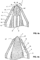
- FIG 4c a three-dimensional representation of the spray head tip 7 is shown according to the invention.
- the component outlets 8 and 8 'outside the cap 10 open out of the housing component 9.
- FIGS. 5a to 5d Figure 4 shows front views of various embodiments of sprayer tips according to the present invention.
- the sprayer tips differ in the number of component outlets and in the number of sloping surfaces from which the component outlets exit.
- FIG. 5a is a spray head tip according to the embodiment of FIGS. 4a to 4c shown.
- the spray head tip protrudes from the cap 10 in such a way that four compressed gas outlet channels 17, 17 ', 17 “and 17”' are formed between the webs 16, 16 ', 16 "and 16”'.
- the compressed gas outlet channels are arranged annularly around the component outlets 8 and 8 '.
- the webs 16 "and 16"' are arranged next to this connecting line, or on a line perpendicular to this.
- FIG. 5b a spray head tip with three component outlets 8, 8 'and 8 "is shown, the three mutually inclined surfaces 18, 18' and 18" open.
- the webs come underneath the surfaces 18, 18' and 18". to lie.
- the cut lines of the surfaces 18, 18 'and 18 meanet at the center of the spray tip and thus form a tip-like shield 19.
- FIGS. 5c and 5d four surfaces 18, 18 ', 18 "and 18'” are provided, which run obliquely to the longitudinal axis of the spray head and whose cutting lines meet at a point.
- two component outlets 8 and 8 ' are provided which open out of two opposite surfaces 18 and 18'.
- four component outlets 8, 8 ', 8 "and 8'” are provided, each opening out of one of the surfaces 18, 18 ', 18 "and 18"'.
- the surfaces from which the component outlets open are arranged symmetrically and their surface normals intersect with the longitudinal axis of the spray head.
- the surfaces can also be provided asymmetrically, their surface normals can run alongside the longitudinal axis of the spray head and their surfaces can also be curved or wound. It is essential that the component outlets are directed obliquely outwards and preferably the surfaces form a shielding between them.
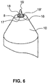
- FIG. 6 a further embodiment of a spray tip with an elongate shielding means 19 is shown.
- the shielding means 19 projects like a plate between the surfaces 18 and 18 '. It protrudes substantially from the line of communication formed by the intersecting surfaces 18 and 18 'along the longitudinal axis of the spray head from the spray tip.
- Such a shielding means in addition to the slanted component outlets, prevents unwanted premature mixing of various components, thus preventing sticking of the sprayhead.
- FIGS. 7 and 8a to c another embodiment of a spray head and a spray device according to the present invention is shown. Components with the components according to the embodiment of the FIGS. 1 to 4 match, bear the same reference numerals.
- FIG. 7 the spray head 5 and a portion of the double syringe 1 is shown.
- the double syringe 1 has two containers 2 and 2 ', to each of which a container outlet 3 and 3' is connected.
- a double piston 4 is provided as a discharge device for discharging the components from the containers 2 and 2'.
- the housing component 9 has a component channel 20, which serves as a mixing channel and are arranged in the mixing elements 21.
- the housing further has two access passages 22 and 22 'which connect the reservoir outlets 3, 3' to the component passage 20 when the housing member 9 is fitted over the reservoir outlets 3 and 3 'of the double syringe 1. If the two components are discharged from the containers 2 and 2 'by means of the double piston 4 through the container outlets 3, 3', they come into contact in the component channel 20 and are replaced by a further insertion of the double piston 4 in the container 2 and 2 'within the Component channel 20 is advanced along the mixing element 21, whereby due to the mixing elements 21, a mixture of the two components takes place within the spray head.
- This embodiment is therefore suitable for the spraying of substances which must be mixed shortly before their application, but do not cure so fast that they stick the component channel, or the mixing elements.
- the cap 10 is placed with the compressed gas supply channel 13, so that between the housing member 9 and the cap 10 of the annular channel 12 is formed.
- webs 16 and 16 ' are arranged on the outer circumference in the region of the spray head.
- the webs 16, 16 ' abut against the inner wall 14 of the cap 10.
- the component channel 20 is divided in the region of its output by the mixing elements 21 in such a way that two component outlets 23 and 23 'arranged next to one another are formed. When discharging the mixture from the component channel 20, the mixture is therefore expelled through two separate, closely spaced component outlets 23, 23 '.
- FIG. 8a a longitudinal section through the spray head tip 7 is shown, which extends through two opposite webs 16, 16 '.
- the component channel 20 with the mixing elements 21 is formed inside the building component 9 in the longitudinal direction.
- the component outlets 23 and 23 ' are arranged at two mutually angled surfaces 18 and 18'.
- the function of the inclined surfaces 18 and 18 ' is the same as in the previous embodiment.
- FIG. 8b is a longitudinal section through the spray head tip 7 along a plane between two webs 16 and 16 'shown.
- the component channel 20 is shown with the mixing elements 21, which has no outlet in this sectional plane.
- the annular channel 12 is formed, which opens in the region of the spray head 7 in the compressed gas outlet channels 17 and 17 '.
- the spray head tip 7 corresponds in the three-dimensional representation of in Figure 4c shown tip. It can be seen that in the area of the spray head, the housing member protrudes through the opening 11 of the cap 10, so that the component outlets 23 and 23 'as well as the outlets 8 and 8' in Figure 4c except for Cap 10 come to rest. On the outer circumference of the housing part 9, the webs 16, 16 'can be seen. Between the webs 16, 16 ', the Druckgasauslasskanäle 17, 17' are arranged. The surfaces 18, 18 'are arranged at an angle to one another and form a shielding means 19 between the component outlets 23, 23'.
- the design of the compressed gas line according to the present invention with an annular channel and therein webs for controlling and focusing the discharge of compressed gas at the spray head of the spray device corresponds to that of the embodiment according to the FIGS. 1 to 4 .
- the compressed gas stream can be selectively focused and arranged in a selected manner relative to the component outlets.
- the arrangement of the component outlets on different surfaces, which are arranged at an angle to each other, prevents uncontrolled mixing of the discharged components, and the negative effects of vacuum formation as the compressed gas flows past are reduced.
- spray direction that direction which corresponds to the longitudinal axis of the spray device in the rule.
- a substance is sprayed at an angle to the longitudinal axis of the spray device.
- the normal which runs perpendicular to an outlet opening of an inventive annular channel, indicate the spray direction, since a compressed gas stream, which is composed of the sum of the exiting from all Druckgasauslassten streams flows in this direction.
Landscapes
- Chemical & Material Sciences (AREA)
- Chemical Kinetics & Catalysis (AREA)
- Health & Medical Sciences (AREA)
- Surgery (AREA)
- Life Sciences & Earth Sciences (AREA)
- Biomedical Technology (AREA)
- Animal Behavior & Ethology (AREA)
- Engineering & Computer Science (AREA)
- Dispersion Chemistry (AREA)
- Heart & Thoracic Surgery (AREA)
- Medical Informatics (AREA)
- Molecular Biology (AREA)
- Nuclear Medicine, Radiotherapy & Molecular Imaging (AREA)
- General Health & Medical Sciences (AREA)
- Public Health (AREA)
- Veterinary Medicine (AREA)
- Nozzles (AREA)
- Surgical Instruments (AREA)
- Containers And Packaging Bodies Having A Special Means To Remove Contents (AREA)
Claims (15)
- Une tête de pulvérisation pour dispositif de pulvérisation pour pulvériser au moins une substance resp. un composant qui comprend :- au moins un canal à substance resp. à composant (6, 6'; 20) ayant au moins une sortie à composant (8, 8'; 23, 23') débouchant d'une pointe (7) de la tête de pulvérisation,- un canal annulaire (12) pour un gaz sous pression entourant au moins en partie le canal à composant (6, 6'; 20) en direction longitudinale et débouchant de la tête de pulvérisation (5) à la pointe (7) de la tête de pulvérisation, et- un canal d'alimentation (13) en gaz sous pression pour introduire du gaz sous pression dans le canal annulaire (12),dans laquelle le canal annulaire (12) présente plusieurs nervures (16, 16', 16", 16"') qui divisent le canal annulaire (12), au moins dans la région de la pointe (7) de la tête de pulvérisation, en canaux de sortie du gaz sous pression (17, 17', 17", 17'") séparés les uns des autres, caractérisée en ce que, ou bien(a) au moins deux canaux à composant (6, 6') sont prévus pour des composantes respectivement différentes, dont les sorties à composant (8, 8') débouchent l'une à côté de l'autre de la pointe (7) de la tête de pulvérisation, ou bien(b) un canal unique à substance resp. de mélange (20) est prévu, qui se divise en deux sorties à composant (23, 23'), arrangées l'une à côté de l'autre, à la pointe (7) de la tête de pulvérisation.
- La tête de pulvérisation selon la revendication 1, caractérisée en ce que les nervures (16, 16') sont arrangées en direction de la pointe (7) de la tête de pulvérisation tel que les canaux de sortie du gaz sous pression (17, 17', 17" , 17"') se rétrécissent en direction de la pointe (7) de la tête de pulvérisation.
- Tête de pulvérisation selon une des revendications précédentes, caractérisée en ce que les canaux à composant (6, 6'), respectivement le canal à substance ou de mélange (20) sont formés dans un boîtier (9) et le canal annulaire (12) est formé entre une paroi extérieure (15) du boîtier et une paroi intérieure (14) d'un capuchon (10) posé sur le boîtier, où le capuchon (10) est monté de manière étanche à une extrémité avec le boîtier (9) et présente sur l'autre extrémité une ouverture (11).
- Tête de pulvérisation selon la revendication 3, caractérisée en ce que le canal d'alimentation en gaz sous pression (13) est prévu sur le capuchon (10).
- Tête de pulvérisation selon la revendication 3 ou 4, caractérisée en ce que les nervures (16, 16', 16", 16"') sont arrangées sur la paroi intérieure (14) du capuchon et/ou la paroi extérieure (15) du boîtier (9) de manière saillante en direction radiale.
- Tête de pulvérisation selon une des revendications précédentes, caractérisée en ce que un moyen d'isolation (19) est arrangé entre deux sorties à composant (8, 8', 23, 23').
- Tête de pulvérisation selon une des revendications précédentes, caractérisée en ce que les sorties à composant (8, 8', 23, 23') sont arrangées sur la pointe (7) de la tête de pulvérisation s'étendant en direction de pulvérisation au-delà des canaux de sortie du gaz sous pression (17, 17', 17", 17"').
- Tête de pulvérisation selon une des revendications précédentes, caractérisé en ce que deux sorties à composant (8, 8', 23, 23') sont prévues, qui débouchent respectivement sur une surface (18, 18') de la pointe (7) de tête de pulvérisation, ou les surfaces (18, 18') renferment l'une par rapport à l'autre un angle tel que les sorties à composant (8, 8', 23, 23') sont orientées vers l'extérieur et de manière décalée par rapport à la direction de pulvérisation.
- Tête de pulvérisation selon la revendication 8, caractérisée en ce que les nervures (16, 16') sont arrangés tel que les canaux de sortie du gaz sous pression (17, 17', 17", 17"') sont arrangés à côté d'une ligne de connexion de deux sorties à composant (8, 8', 23, 23').
- Tête de pulvérisation selon la revendication 9, caractérisée en ce que deux des nervures (16, 16') sont arrangés sur une ligne de connexion de deux sorties à composant (8, 8', 23, 23'), tel que le gaz sous pression ne s'écoule pas directement sur les sorties à composant.
- Tête de pulvérisation selon la revendication 10, caractérisée en ce que les surfaces (18, 18') se rencontrent en une ligne de d'intersection, et que deux des nervures (16", 16"') sont arrangés d'un côté et d'autre le long de la ligne d'intersection, tel que pour chacune des surfaces (18, 18') les canaux de sortie du gaz sous pression (17, 17') sont formés des deux côtés de la surface correspondante (18, 18').
- Tête de pulvérisation selon une des revendications 1 à 7, caractérisée en ce que la pointe de tête de pulvérisation présente au moins deux sorties à composant (8, 8', 8") et au moins deux surfaces (18, 18', 18", 18"') qui s'étendent de manière inclinée à l'axe longitudinal de la tête de pulvérisation, où respectivement une sortie à composant débouche de chacune des surfaces, et que pour chacune des surfaces (18, 18', 18" , 18"') une des nervures (16, 16', 16", 16'") est arrangée en dessous de la surface correspondante.
- Dispositif de pulvérisation ayant une tête de pulvérisation (5) selon une des revendications 1 à 12.
- Dispositif de pulvérisation selon la revendication 13, caractérisé en ce que au moins deux réservoirs (2, 2') sont prévus pour recevoir respectivement des composants différents, qui respectivement présentent une sortie de réservoir (3, 3'), qui débouchent dans au moins un canal à composant (16, 16' ; 20) de la tête de pulvérisation (5) et un dispositif de décharge (4) pour décharger les composants hors du récipient (2, 2').
- Dispositif de pulvérisation selon une des revendications 13 ou 14, caractérisé en ce que le récipient (2, 2') est formé par une cartouche double ou double seringue (1).
Applications Claiming Priority (2)
| Application Number | Priority Date | Filing Date | Title |
|---|---|---|---|
| CH01706/08A CH699808A1 (de) | 2008-10-30 | 2008-10-30 | Sprühkopf und Sprühvorrichtung mit einem solchen Sprühkopf. |
| PCT/CH2009/000341 WO2010048734A1 (fr) | 2008-10-30 | 2009-10-23 | Tête de pulvérisation et dispositif de pulvérisation avec conduit de gaz sous pression |
Publications (2)
| Publication Number | Publication Date |
|---|---|
| EP2340125A1 EP2340125A1 (fr) | 2011-07-06 |
| EP2340125B1 true EP2340125B1 (fr) | 2016-03-23 |
Family
ID=40089922
Family Applications (1)
| Application Number | Title | Priority Date | Filing Date |
|---|---|---|---|
| EP09741185.4A Active EP2340125B1 (fr) | 2008-10-30 | 2009-10-23 | Tête de pulvérisation et dispositif de pulvérisation avec conduit de gaz sous pression |
Country Status (6)
| Country | Link |
|---|---|
| US (1) | US8534575B2 (fr) |
| EP (1) | EP2340125B1 (fr) |
| JP (1) | JP5658162B2 (fr) |
| CN (1) | CN102196865B (fr) |
| CH (1) | CH699808A1 (fr) |
| WO (1) | WO2010048734A1 (fr) |
Families Citing this family (30)
| Publication number | Priority date | Publication date | Assignee | Title |
|---|---|---|---|---|
| EP2375993B1 (fr) * | 2009-01-13 | 2017-11-22 | Medmix Systems AG | Dispositif de distribution assisté par du gaz comprimé |
| RU2567638C2 (ru) * | 2010-07-20 | 2015-11-10 | Зульцер Микспэк Аг | Статический распылительный смеситель |
| US9770728B2 (en) * | 2010-07-20 | 2017-09-26 | Sulzer Mixpac Ag | Static spray mixer |
| CH703974A1 (de) | 2010-10-15 | 2012-04-30 | Medmix Systems Ag | Medizinischer Sprühkopf mit Druckgasunterstützung. |
| ES2699955T3 (es) * | 2011-05-23 | 2019-02-13 | Sulzer Mixpac Ag | Combinación de un mezclador pulverizador estático con una pieza intermedia |
| JP5779467B2 (ja) * | 2011-09-30 | 2015-09-16 | 住友ベークライト株式会社 | 生体組織接着剤塗布用具およびノズルヘッド |
| US9878335B2 (en) * | 2012-05-14 | 2018-01-30 | Sulzer Mixpac Ag | Spray mixer for mixing and spraying at least two flowable components |
| DE102013003688A1 (de) * | 2012-10-26 | 2014-04-30 | Fraunhofer-Gesellschaft zur Förderung der angewandten Forschung e.V. | Kombinationsdüse sowie Vorrichtung für den Auftrag eines viskosen Materials auf eine Bauteilkante |
| JP6132404B2 (ja) * | 2013-06-26 | 2017-05-24 | アネスト岩田株式会社 | 塗布器具 |
| DE102013214032A1 (de) | 2013-07-17 | 2015-01-22 | Aesculap Ag | Sprühapplikator und Austragsvorrichtung zum Versprühen eines Mehrkomponenten-Fluids |
| EP3125774B1 (fr) | 2014-04-04 | 2020-05-27 | HyperBranch Medical Technology, Inc. | Applicateur à pulvérisation à pointe étendue pour un joint d'étanchéité à deux composants, et son procédé d'utilisation |
| CH709684A1 (de) | 2014-05-22 | 2015-11-30 | Medmix Systems Ag | Laparoskopischer Sprayapplikator und Adapter. |
| CN105057154B (zh) * | 2015-08-14 | 2017-06-16 | 重庆理工大学 | 一种独立式多源共聚焦超声雾化热解喷涂反应室 |
| US9572555B1 (en) * | 2015-09-24 | 2017-02-21 | Ethicon, Inc. | Spray or drip tips having multiple outlet channels |
| EP3165288B1 (fr) * | 2015-11-06 | 2020-08-26 | ViscoTec Pumpen- und Dosiertechnik GmbH | Dispositif de vaporisation |
| US20170312769A1 (en) * | 2016-05-02 | 2017-11-02 | Precision Valve & Automation, Inc. | Mixing valve assembly having an atomizing spray tip |
| US10981185B2 (en) | 2016-08-13 | 2021-04-20 | Nordson Corporation | Systems and methods for two-component mixing in a jetting dispenser |
| US10231846B2 (en) | 2016-08-19 | 2019-03-19 | Stryker European Holdings I, Llc | Bone graft delivery loading assembly |
| CN107456317A (zh) * | 2017-07-19 | 2017-12-12 | 江苏威克斯医疗科技有限公司 | 一种用于外耳道冲洗的医疗器械装置 |
| WO2019118423A1 (fr) * | 2017-12-11 | 2019-06-20 | Waugh Nathaniel L | Applicateur d'aérosol de produits chimiques en mousse expansive |
| EP3801707A1 (fr) * | 2018-05-29 | 2021-04-14 | SHL Medical AG | Ensemble buse et cartouche |
| CN108686862B (zh) * | 2018-06-28 | 2023-08-25 | 山东万事达建筑钢品股份有限公司 | 一种悬臂式净化板喷胶系统 |
| JP2020036824A (ja) * | 2018-09-05 | 2020-03-12 | 住友ベークライト株式会社 | 生体組織接着剤塗布用具 |
| CN110038745B (zh) * | 2019-03-29 | 2024-05-14 | 江汉大学 | 液滴细分的装置和方法 |
| DE102019205743A1 (de) * | 2019-04-18 | 2020-10-22 | Glatt Gesellschaft Mit Beschränkter Haftung | Verfahren zur Steuerung oder Regelung des Volumenstroms einer Düse |
| JP6864840B2 (ja) * | 2019-06-11 | 2021-04-28 | ニプロ株式会社 | 薬剤供給器具 |
| CN110328115A (zh) * | 2019-07-04 | 2019-10-15 | 韶关欧亚特电子制品有限公司 | 一种活塞式胶枪 |
| US20210100543A1 (en) * | 2019-10-04 | 2021-04-08 | Ethicon, Inc. | Dispensing systems and devices having anti-clogging spray tips for dispensing two or more fluids that react together |
| WO2022014159A1 (fr) * | 2020-07-16 | 2022-01-20 | テルモ株式会社 | Applicateur médical |
| WO2024062453A1 (fr) * | 2022-09-23 | 2024-03-28 | 3M Innovative Properties Company | Buse de fluide et système de fluide |
Family Cites Families (13)
| Publication number | Priority date | Publication date | Assignee | Title |
|---|---|---|---|---|
| US6018A (en) * | 1849-01-09 | Improvement in bog-cutters | ||
| US3022A (en) * | 1843-03-30 | Machine for bending stibrups for paddle-wheels of steam and other | ||
| JPS61167472A (ja) * | 1985-01-18 | 1986-07-29 | Masuzo Hamamura | 低温気体による減圧内溶融金属溶射法及びその装置 |
| AT400304B (de) * | 1994-02-28 | 1995-12-27 | Immuno Ag | Vorrichtung zur applikation eines mehrkomponenten-gewebeklebstoffes |
| US5605541A (en) | 1994-12-07 | 1997-02-25 | E. R. Squibb And Sons, Inc. | Fibrin sealant applicatoor |
| EP0738498A1 (fr) * | 1995-04-18 | 1996-10-23 | Machida Endoscope Co., Ltd | Appareil chirurgical de pulvérisation d'un adhésif |
| US6158676A (en) * | 1996-06-21 | 2000-12-12 | Hughes Technology Group, L.L.C. | Micro-atomizing device |
| US6062492A (en) * | 1998-05-15 | 2000-05-16 | Sealant Equipment & Engineering, Inc. | Viscous material dispense system |
| JP3549741B2 (ja) * | 1998-09-08 | 2004-08-04 | 日本スピードショア株式会社 | 霧状体供給装置 |
| US6951310B2 (en) * | 2002-06-06 | 2005-10-04 | Anderson Steven R | Spray head and air atomizing assembly |
| AU2003291973A1 (en) * | 2002-12-20 | 2004-07-14 | Lifecycle Pharma A/S | A self-cleaning spray nozzle |
| US7611494B2 (en) * | 2005-02-08 | 2009-11-03 | Confluent Surgical, Inc. | Spray for fluent materials |
| KR20080005937A (ko) * | 2005-03-31 | 2008-01-15 | 윌리엄 헨리 리차즈 | 압축 공기 포말 시스템용 살포 및 폭기 장치 |
-
2008
- 2008-10-30 CH CH01706/08A patent/CH699808A1/de not_active Application Discontinuation
-
2009
- 2009-10-23 EP EP09741185.4A patent/EP2340125B1/fr active Active
- 2009-10-23 JP JP2011533504A patent/JP5658162B2/ja active Active
- 2009-10-23 US US13/124,789 patent/US8534575B2/en active Active
- 2009-10-23 CN CN200980143298.9A patent/CN102196865B/zh active Active
- 2009-10-23 WO PCT/CH2009/000341 patent/WO2010048734A1/fr active Application Filing
Also Published As
| Publication number | Publication date |
|---|---|
| JP2012506739A (ja) | 2012-03-22 |
| JP5658162B2 (ja) | 2015-01-21 |
| US20110253806A1 (en) | 2011-10-20 |
| CH699808A1 (de) | 2010-04-30 |
| US8534575B2 (en) | 2013-09-17 |
| CN102196865B (zh) | 2015-05-13 |
| CN102196865A (zh) | 2011-09-21 |
| WO2010048734A1 (fr) | 2010-05-06 |
| EP2340125A1 (fr) | 2011-07-06 |
Similar Documents
| Publication | Publication Date | Title |
|---|---|---|
| EP2340125B1 (fr) | Tête de pulvérisation et dispositif de pulvérisation avec conduit de gaz sous pression | |
| DE69819017T2 (de) | Vernebelungskopf und Vernebelungsvorrichtung | |
| AT392044B (de) | Spritzduese sowie die spritzduese enthaltende vorrichtung | |
| EP2969234B1 (fr) | Buse de pulvérisation pour sortie d'eau sanitaire et robinet sanitaire pourvu d'une sortie d'eau | |
| DE102006008874B4 (de) | Dosiervorrichtung mit einer manuell betätigbaren Pumpeinrichtung | |
| EP2627259B1 (fr) | Tête de pulvérisation medical avec gaz sous pression | |
| EP2527041B1 (fr) | Pièce intermédiaire pour un mélangeur statique de pulvérisation | |
| DE2549974A1 (de) | Vorrichtung zum zerstaeuben von fliessfaehigen medien wie z.b. farben, lacken u.dgl. | |
| EP2595759A1 (fr) | Mélangeur à pulvérisation statique | |
| DE3501145A1 (de) | Stroemungsverstaerkende fluessigkeitszerstaeubungsduese | |
| DE2705706A1 (de) | Rund- oder ringstrahlduese zum erzeugen und abstrahlen eines nebels oder aerosols | |
| EP2595758B1 (fr) | Mélangeur de pulvérisation statique | |
| DE3820537A1 (de) | Spruehvorrichtung | |
| EP2286925B1 (fr) | Pulvérisateur avec mélangeur statique | |
| DE2517715C2 (de) | Verfahren und einrichtung zum mischen und/oder dispergieren und abstrahlen der komponenten eines fliessfaehigen materials zum beschichten von oberflaechen | |
| EP0782866B1 (fr) | Tête de diffuseur, en particulier pour le traitement médicamenteux de la gorge | |
| DE602004010148T2 (de) | Schaumdüse | |
| EP0497255A2 (fr) | Buse de débit pour milieux | |
| DE4312994C2 (de) | Vorrichtung zur Verspritzung von Suspensionen, insbesondere Mörteln | |
| DE3243230C2 (de) | Drallkörperdüse für Spritzanlagen | |
| DE2742018A1 (de) | Mischkopf fuer zweikomponenten- spritzpistole | |
| EP3638424B1 (fr) | Buse de pulverisation | |
| DE2832286C2 (de) | Düsenvorrichtung für Halon-Feuerlöschgeräte | |
| WO2020089171A1 (fr) | Buse de pulvérisation | |
| WO2006024450A2 (fr) | Sonde de pulverisation |
Legal Events
| Date | Code | Title | Description |
|---|---|---|---|
| PUAI | Public reference made under article 153(3) epc to a published international application that has entered the european phase |
Free format text: ORIGINAL CODE: 0009012 |
|
| 17P | Request for examination filed |
Effective date: 20110328 |
|
| AK | Designated contracting states |
Kind code of ref document: A1 Designated state(s): AT BE BG CH CY CZ DE DK EE ES FI FR GB GR HR HU IE IS IT LI LT LU LV MC MK MT NL NO PL PT RO SE SI SK SM TR |
|
| AX | Request for extension of the european patent |
Extension state: AL BA RS |
|
| DAX | Request for extension of the european patent (deleted) | ||
| REG | Reference to a national code |
Ref country code: DE Ref legal event code: R079 Ref document number: 502009012297 Country of ref document: DE Free format text: PREVIOUS MAIN CLASS: B05B0007060000 Ipc: A61B0017000000 |
|
| RIC1 | Information provided on ipc code assigned before grant |
Ipc: B05C 17/005 20060101ALI20150901BHEP Ipc: B05B 7/04 20060101ALI20150901BHEP Ipc: A61B 17/00 20060101AFI20150901BHEP Ipc: B05B 7/08 20060101ALI20150901BHEP Ipc: B05B 7/24 20060101ALI20150901BHEP |
|
| GRAP | Despatch of communication of intention to grant a patent |
Free format text: ORIGINAL CODE: EPIDOSNIGR1 |
|
| INTG | Intention to grant announced |
Effective date: 20151016 |
|
| GRAS | Grant fee paid |
Free format text: ORIGINAL CODE: EPIDOSNIGR3 |
|
| GRAA | (expected) grant |
Free format text: ORIGINAL CODE: 0009210 |
|
| AK | Designated contracting states |
Kind code of ref document: B1 Designated state(s): AT BE BG CH CY CZ DE DK EE ES FI FR GB GR HR HU IE IS IT LI LT LU LV MC MK MT NL NO PL PT RO SE SI SK SM TR |
|
| REG | Reference to a national code |
Ref country code: GB Ref legal event code: FG4D Free format text: NOT ENGLISH |
|
| REG | Reference to a national code |
Ref country code: CH Ref legal event code: EP |
|
| REG | Reference to a national code |
Ref country code: AT Ref legal event code: REF Ref document number: 782304 Country of ref document: AT Kind code of ref document: T Effective date: 20160415 |
|
| REG | Reference to a national code |
Ref country code: IE Ref legal event code: FG4D Free format text: LANGUAGE OF EP DOCUMENT: GERMAN |
|
| REG | Reference to a national code |
Ref country code: DE Ref legal event code: R096 Ref document number: 502009012297 Country of ref document: DE |
|
| REG | Reference to a national code |
Ref country code: LT Ref legal event code: MG4D |
|
| REG | Reference to a national code |
Ref country code: NL Ref legal event code: MP Effective date: 20160323 |
|
| PG25 | Lapsed in a contracting state [announced via postgrant information from national office to epo] |
Ref country code: NO Free format text: LAPSE BECAUSE OF FAILURE TO SUBMIT A TRANSLATION OF THE DESCRIPTION OR TO PAY THE FEE WITHIN THE PRESCRIBED TIME-LIMIT Effective date: 20160623 Ref country code: FI Free format text: LAPSE BECAUSE OF FAILURE TO SUBMIT A TRANSLATION OF THE DESCRIPTION OR TO PAY THE FEE WITHIN THE PRESCRIBED TIME-LIMIT Effective date: 20160323 Ref country code: GR Free format text: LAPSE BECAUSE OF FAILURE TO SUBMIT A TRANSLATION OF THE DESCRIPTION OR TO PAY THE FEE WITHIN THE PRESCRIBED TIME-LIMIT Effective date: 20160624 |
|
| PG25 | Lapsed in a contracting state [announced via postgrant information from national office to epo] |
Ref country code: NL Free format text: LAPSE BECAUSE OF FAILURE TO SUBMIT A TRANSLATION OF THE DESCRIPTION OR TO PAY THE FEE WITHIN THE PRESCRIBED TIME-LIMIT Effective date: 20160323 Ref country code: SE Free format text: LAPSE BECAUSE OF FAILURE TO SUBMIT A TRANSLATION OF THE DESCRIPTION OR TO PAY THE FEE WITHIN THE PRESCRIBED TIME-LIMIT Effective date: 20160323 Ref country code: LT Free format text: LAPSE BECAUSE OF FAILURE TO SUBMIT A TRANSLATION OF THE DESCRIPTION OR TO PAY THE FEE WITHIN THE PRESCRIBED TIME-LIMIT Effective date: 20160323 Ref country code: LV Free format text: LAPSE BECAUSE OF FAILURE TO SUBMIT A TRANSLATION OF THE DESCRIPTION OR TO PAY THE FEE WITHIN THE PRESCRIBED TIME-LIMIT Effective date: 20160323 |
|
| REG | Reference to a national code |
Ref country code: FR Ref legal event code: PLFP Year of fee payment: 8 |
|
| PG25 | Lapsed in a contracting state [announced via postgrant information from national office to epo] |
Ref country code: EE Free format text: LAPSE BECAUSE OF FAILURE TO SUBMIT A TRANSLATION OF THE DESCRIPTION OR TO PAY THE FEE WITHIN THE PRESCRIBED TIME-LIMIT Effective date: 20160323 Ref country code: IS Free format text: LAPSE BECAUSE OF FAILURE TO SUBMIT A TRANSLATION OF THE DESCRIPTION OR TO PAY THE FEE WITHIN THE PRESCRIBED TIME-LIMIT Effective date: 20160723 Ref country code: PL Free format text: LAPSE BECAUSE OF FAILURE TO SUBMIT A TRANSLATION OF THE DESCRIPTION OR TO PAY THE FEE WITHIN THE PRESCRIBED TIME-LIMIT Effective date: 20160323 |
|
| PG25 | Lapsed in a contracting state [announced via postgrant information from national office to epo] |
Ref country code: RO Free format text: LAPSE BECAUSE OF FAILURE TO SUBMIT A TRANSLATION OF THE DESCRIPTION OR TO PAY THE FEE WITHIN THE PRESCRIBED TIME-LIMIT Effective date: 20160323 Ref country code: SM Free format text: LAPSE BECAUSE OF FAILURE TO SUBMIT A TRANSLATION OF THE DESCRIPTION OR TO PAY THE FEE WITHIN THE PRESCRIBED TIME-LIMIT Effective date: 20160323 Ref country code: ES Free format text: LAPSE BECAUSE OF FAILURE TO SUBMIT A TRANSLATION OF THE DESCRIPTION OR TO PAY THE FEE WITHIN THE PRESCRIBED TIME-LIMIT Effective date: 20160323 Ref country code: SK Free format text: LAPSE BECAUSE OF FAILURE TO SUBMIT A TRANSLATION OF THE DESCRIPTION OR TO PAY THE FEE WITHIN THE PRESCRIBED TIME-LIMIT Effective date: 20160323 Ref country code: CZ Free format text: LAPSE BECAUSE OF FAILURE TO SUBMIT A TRANSLATION OF THE DESCRIPTION OR TO PAY THE FEE WITHIN THE PRESCRIBED TIME-LIMIT Effective date: 20160323 Ref country code: PT Free format text: LAPSE BECAUSE OF FAILURE TO SUBMIT A TRANSLATION OF THE DESCRIPTION OR TO PAY THE FEE WITHIN THE PRESCRIBED TIME-LIMIT Effective date: 20160725 |
|
| PG25 | Lapsed in a contracting state [announced via postgrant information from national office to epo] |
Ref country code: IT Free format text: LAPSE BECAUSE OF FAILURE TO SUBMIT A TRANSLATION OF THE DESCRIPTION OR TO PAY THE FEE WITHIN THE PRESCRIBED TIME-LIMIT Effective date: 20160323 |
|
| REG | Reference to a national code |
Ref country code: DE Ref legal event code: R097 Ref document number: 502009012297 Country of ref document: DE |
|
| PLBE | No opposition filed within time limit |
Free format text: ORIGINAL CODE: 0009261 |
|
| STAA | Information on the status of an ep patent application or granted ep patent |
Free format text: STATUS: NO OPPOSITION FILED WITHIN TIME LIMIT |
|
| PG25 | Lapsed in a contracting state [announced via postgrant information from national office to epo] |
Ref country code: DK Free format text: LAPSE BECAUSE OF FAILURE TO SUBMIT A TRANSLATION OF THE DESCRIPTION OR TO PAY THE FEE WITHIN THE PRESCRIBED TIME-LIMIT Effective date: 20160323 |
|
| PG25 | Lapsed in a contracting state [announced via postgrant information from national office to epo] |
Ref country code: BE Free format text: LAPSE BECAUSE OF NON-PAYMENT OF DUE FEES Effective date: 20161031 Ref country code: BG Free format text: LAPSE BECAUSE OF FAILURE TO SUBMIT A TRANSLATION OF THE DESCRIPTION OR TO PAY THE FEE WITHIN THE PRESCRIBED TIME-LIMIT Effective date: 20160623 |
|
| 26N | No opposition filed |
Effective date: 20170102 |
|
| PG25 | Lapsed in a contracting state [announced via postgrant information from national office to epo] |
Ref country code: SI Free format text: LAPSE BECAUSE OF FAILURE TO SUBMIT A TRANSLATION OF THE DESCRIPTION OR TO PAY THE FEE WITHIN THE PRESCRIBED TIME-LIMIT Effective date: 20160323 |
|
| REG | Reference to a national code |
Ref country code: CH Ref legal event code: PL |
|
| REG | Reference to a national code |
Ref country code: IE Ref legal event code: MM4A |
|
| PG25 | Lapsed in a contracting state [announced via postgrant information from national office to epo] |
Ref country code: CH Free format text: LAPSE BECAUSE OF NON-PAYMENT OF DUE FEES Effective date: 20161031 Ref country code: LI Free format text: LAPSE BECAUSE OF NON-PAYMENT OF DUE FEES Effective date: 20161031 |
|
| PG25 | Lapsed in a contracting state [announced via postgrant information from national office to epo] |
Ref country code: LU Free format text: LAPSE BECAUSE OF NON-PAYMENT OF DUE FEES Effective date: 20161023 |
|
| REG | Reference to a national code |
Ref country code: FR Ref legal event code: PLFP Year of fee payment: 9 |
|
| PG25 | Lapsed in a contracting state [announced via postgrant information from national office to epo] |
Ref country code: IE Free format text: LAPSE BECAUSE OF NON-PAYMENT OF DUE FEES Effective date: 20161023 |
|
| REG | Reference to a national code |
Ref country code: BE Ref legal event code: MM Effective date: 20161031 |
|
| REG | Reference to a national code |
Ref country code: AT Ref legal event code: MM01 Ref document number: 782304 Country of ref document: AT Kind code of ref document: T Effective date: 20161023 |
|
| PG25 | Lapsed in a contracting state [announced via postgrant information from national office to epo] |
Ref country code: AT Free format text: LAPSE BECAUSE OF NON-PAYMENT OF DUE FEES Effective date: 20161023 |
|
| PG25 | Lapsed in a contracting state [announced via postgrant information from national office to epo] |
Ref country code: HU Free format text: LAPSE BECAUSE OF FAILURE TO SUBMIT A TRANSLATION OF THE DESCRIPTION OR TO PAY THE FEE WITHIN THE PRESCRIBED TIME-LIMIT; INVALID AB INITIO Effective date: 20091023 Ref country code: CY Free format text: LAPSE BECAUSE OF FAILURE TO SUBMIT A TRANSLATION OF THE DESCRIPTION OR TO PAY THE FEE WITHIN THE PRESCRIBED TIME-LIMIT Effective date: 20160323 |
|
| PG25 | Lapsed in a contracting state [announced via postgrant information from national office to epo] |
Ref country code: MT Free format text: LAPSE BECAUSE OF FAILURE TO SUBMIT A TRANSLATION OF THE DESCRIPTION OR TO PAY THE FEE WITHIN THE PRESCRIBED TIME-LIMIT Effective date: 20160323 Ref country code: HR Free format text: LAPSE BECAUSE OF FAILURE TO SUBMIT A TRANSLATION OF THE DESCRIPTION OR TO PAY THE FEE WITHIN THE PRESCRIBED TIME-LIMIT Effective date: 20160323 Ref country code: MC Free format text: LAPSE BECAUSE OF FAILURE TO SUBMIT A TRANSLATION OF THE DESCRIPTION OR TO PAY THE FEE WITHIN THE PRESCRIBED TIME-LIMIT Effective date: 20160323 Ref country code: MK Free format text: LAPSE BECAUSE OF FAILURE TO SUBMIT A TRANSLATION OF THE DESCRIPTION OR TO PAY THE FEE WITHIN THE PRESCRIBED TIME-LIMIT Effective date: 20160323 Ref country code: TR Free format text: LAPSE BECAUSE OF FAILURE TO SUBMIT A TRANSLATION OF THE DESCRIPTION OR TO PAY THE FEE WITHIN THE PRESCRIBED TIME-LIMIT Effective date: 20160323 |
|
| REG | Reference to a national code |
Ref country code: FR Ref legal event code: PLFP Year of fee payment: 10 |
|
| REG | Reference to a national code |
Ref country code: DE Ref legal event code: R081 Ref document number: 502009012297 Country of ref document: DE Owner name: MEDMIX SWITZERLAND AG, CH Free format text: FORMER OWNER: MEDMIX SYSTEMS AG, ROTKREUZ, CH Ref country code: DE Ref legal event code: R082 Ref document number: 502009012297 Country of ref document: DE Representative=s name: HOEGER, STELLRECHT & PARTNER PATENTANWAELTE MB, DE Ref country code: DE Ref legal event code: R081 Ref document number: 502009012297 Country of ref document: DE Owner name: SULZER MIXPAC AG, CH Free format text: FORMER OWNER: MEDMIX SYSTEMS AG, ROTKREUZ, CH Ref country code: DE Ref legal event code: R082 Ref document number: 502009012297 Country of ref document: DE Representative=s name: MANITZ FINSTERWALD PATENT- UND RECHTSANWALTSPA, DE |
|
| REG | Reference to a national code |
Ref country code: GB Ref legal event code: 732E Free format text: REGISTERED BETWEEN 20190718 AND 20190724 |
|
| REG | Reference to a national code |
Ref country code: DE Ref legal event code: R082 Ref document number: 502009012297 Country of ref document: DE Representative=s name: MANITZ FINSTERWALD PATENT- UND RECHTSANWALTSPA, DE |
|
| REG | Reference to a national code |
Ref country code: DE Ref legal event code: R081 Ref document number: 502009012297 Country of ref document: DE Owner name: MEDMIX SWITZERLAND AG, CH Free format text: FORMER OWNER: SULZER MIXPAC AG, HAAG, CH |
|
| PGFP | Annual fee paid to national office [announced via postgrant information from national office to epo] |
Ref country code: GB Payment date: 20231020 Year of fee payment: 15 |
|
| PGFP | Annual fee paid to national office [announced via postgrant information from national office to epo] |
Ref country code: FR Payment date: 20231024 Year of fee payment: 15 Ref country code: DE Payment date: 20231020 Year of fee payment: 15 |