EP2340076B1 - Medizinische vorrichtung und system zum temporären verschluss einer öffnung in einem körperlumen - Google Patents
Medizinische vorrichtung und system zum temporären verschluss einer öffnung in einem körperlumen Download PDFInfo
- Publication number
- EP2340076B1 EP2340076B1 EP09783062.4A EP09783062A EP2340076B1 EP 2340076 B1 EP2340076 B1 EP 2340076B1 EP 09783062 A EP09783062 A EP 09783062A EP 2340076 B1 EP2340076 B1 EP 2340076B1
- Authority
- EP
- European Patent Office
- Prior art keywords
- balloon
- support structure
- wall
- lumen
- medical device
- Prior art date
- Legal status (The legal status is an assumption and is not a legal conclusion. Google has not performed a legal analysis and makes no representation as to the accuracy of the status listed.)
- Active
Links
Images


Classifications
-
- A—HUMAN NECESSITIES
- A61—MEDICAL OR VETERINARY SCIENCE; HYGIENE
- A61M—DEVICES FOR INTRODUCING MEDIA INTO, OR ONTO, THE BODY; DEVICES FOR TRANSDUCING BODY MEDIA OR FOR TAKING MEDIA FROM THE BODY; DEVICES FOR PRODUCING OR ENDING SLEEP OR STUPOR
- A61M25/00—Catheters; Hollow probes
- A61M25/10—Balloon catheters
- A61M25/1002—Balloon catheters characterised by balloon shape
-
- A—HUMAN NECESSITIES
- A61—MEDICAL OR VETERINARY SCIENCE; HYGIENE
- A61B—DIAGNOSIS; SURGERY; IDENTIFICATION
- A61B17/00—Surgical instruments, devices or methods, e.g. tourniquets
- A61B17/12—Surgical instruments, devices or methods, e.g. tourniquets for ligaturing or otherwise compressing tubular parts of the body, e.g. blood vessels, umbilical cord
- A61B17/12022—Occluding by internal devices, e.g. balloons or releasable wires
- A61B17/12027—Type of occlusion
- A61B17/12036—Type of occlusion partial occlusion
-
- A—HUMAN NECESSITIES
- A61—MEDICAL OR VETERINARY SCIENCE; HYGIENE
- A61B—DIAGNOSIS; SURGERY; IDENTIFICATION
- A61B17/00—Surgical instruments, devices or methods, e.g. tourniquets
- A61B17/12—Surgical instruments, devices or methods, e.g. tourniquets for ligaturing or otherwise compressing tubular parts of the body, e.g. blood vessels, umbilical cord
- A61B17/12022—Occluding by internal devices, e.g. balloons or releasable wires
- A61B17/12027—Type of occlusion
- A61B17/1204—Type of occlusion temporary occlusion
- A61B17/12045—Type of occlusion temporary occlusion double occlusion, e.g. during anastomosis
-
- A—HUMAN NECESSITIES
- A61—MEDICAL OR VETERINARY SCIENCE; HYGIENE
- A61B—DIAGNOSIS; SURGERY; IDENTIFICATION
- A61B17/00—Surgical instruments, devices or methods, e.g. tourniquets
- A61B17/12—Surgical instruments, devices or methods, e.g. tourniquets for ligaturing or otherwise compressing tubular parts of the body, e.g. blood vessels, umbilical cord
- A61B17/12022—Occluding by internal devices, e.g. balloons or releasable wires
- A61B17/12099—Occluding by internal devices, e.g. balloons or releasable wires characterised by the location of the occluder
- A61B17/12104—Occluding by internal devices, e.g. balloons or releasable wires characterised by the location of the occluder in an air passage
-
- A—HUMAN NECESSITIES
- A61—MEDICAL OR VETERINARY SCIENCE; HYGIENE
- A61B—DIAGNOSIS; SURGERY; IDENTIFICATION
- A61B17/00—Surgical instruments, devices or methods, e.g. tourniquets
- A61B17/12—Surgical instruments, devices or methods, e.g. tourniquets for ligaturing or otherwise compressing tubular parts of the body, e.g. blood vessels, umbilical cord
- A61B17/12022—Occluding by internal devices, e.g. balloons or releasable wires
- A61B17/12099—Occluding by internal devices, e.g. balloons or releasable wires characterised by the location of the occluder
- A61B17/12109—Occluding by internal devices, e.g. balloons or releasable wires characterised by the location of the occluder in a blood vessel
- A61B17/12113—Occluding by internal devices, e.g. balloons or releasable wires characterised by the location of the occluder in a blood vessel within an aneurysm
- A61B17/12118—Occluding by internal devices, e.g. balloons or releasable wires characterised by the location of the occluder in a blood vessel within an aneurysm for positioning in conjunction with a stent
-
- A—HUMAN NECESSITIES
- A61—MEDICAL OR VETERINARY SCIENCE; HYGIENE
- A61B—DIAGNOSIS; SURGERY; IDENTIFICATION
- A61B17/00—Surgical instruments, devices or methods, e.g. tourniquets
- A61B17/12—Surgical instruments, devices or methods, e.g. tourniquets for ligaturing or otherwise compressing tubular parts of the body, e.g. blood vessels, umbilical cord
- A61B17/12022—Occluding by internal devices, e.g. balloons or releasable wires
- A61B17/12131—Occluding by internal devices, e.g. balloons or releasable wires characterised by the type of occluding device
- A61B17/12136—Balloons
-
- A—HUMAN NECESSITIES
- A61—MEDICAL OR VETERINARY SCIENCE; HYGIENE
- A61B—DIAGNOSIS; SURGERY; IDENTIFICATION
- A61B17/00—Surgical instruments, devices or methods, e.g. tourniquets
- A61B17/12—Surgical instruments, devices or methods, e.g. tourniquets for ligaturing or otherwise compressing tubular parts of the body, e.g. blood vessels, umbilical cord
- A61B17/12022—Occluding by internal devices, e.g. balloons or releasable wires
- A61B17/12131—Occluding by internal devices, e.g. balloons or releasable wires characterised by the type of occluding device
- A61B17/1214—Coils or wires
- A61B17/12145—Coils or wires having a pre-set deployed three-dimensional shape
-
- A—HUMAN NECESSITIES
- A61—MEDICAL OR VETERINARY SCIENCE; HYGIENE
- A61B—DIAGNOSIS; SURGERY; IDENTIFICATION
- A61B17/00—Surgical instruments, devices or methods, e.g. tourniquets
- A61B17/12—Surgical instruments, devices or methods, e.g. tourniquets for ligaturing or otherwise compressing tubular parts of the body, e.g. blood vessels, umbilical cord
- A61B17/12022—Occluding by internal devices, e.g. balloons or releasable wires
- A61B17/12131—Occluding by internal devices, e.g. balloons or releasable wires characterised by the type of occluding device
- A61B17/1214—Coils or wires
- A61B17/1215—Coils or wires comprising additional materials, e.g. thrombogenic, having filaments, having fibers, being coated
-
- A—HUMAN NECESSITIES
- A61—MEDICAL OR VETERINARY SCIENCE; HYGIENE
- A61B—DIAGNOSIS; SURGERY; IDENTIFICATION
- A61B17/00—Surgical instruments, devices or methods, e.g. tourniquets
- A61B17/12—Surgical instruments, devices or methods, e.g. tourniquets for ligaturing or otherwise compressing tubular parts of the body, e.g. blood vessels, umbilical cord
- A61B17/12022—Occluding by internal devices, e.g. balloons or releasable wires
- A61B17/12131—Occluding by internal devices, e.g. balloons or releasable wires characterised by the type of occluding device
- A61B17/12168—Occluding by internal devices, e.g. balloons or releasable wires characterised by the type of occluding device having a mesh structure
- A61B17/12172—Occluding by internal devices, e.g. balloons or releasable wires characterised by the type of occluding device having a mesh structure having a pre-set deployed three-dimensional shape
-
- A—HUMAN NECESSITIES
- A61—MEDICAL OR VETERINARY SCIENCE; HYGIENE
- A61B—DIAGNOSIS; SURGERY; IDENTIFICATION
- A61B17/00—Surgical instruments, devices or methods, e.g. tourniquets
- A61B17/12—Surgical instruments, devices or methods, e.g. tourniquets for ligaturing or otherwise compressing tubular parts of the body, e.g. blood vessels, umbilical cord
- A61B17/12022—Occluding by internal devices, e.g. balloons or releasable wires
- A61B17/12131—Occluding by internal devices, e.g. balloons or releasable wires characterised by the type of occluding device
- A61B17/12168—Occluding by internal devices, e.g. balloons or releasable wires characterised by the type of occluding device having a mesh structure
- A61B17/12177—Occluding by internal devices, e.g. balloons or releasable wires characterised by the type of occluding device having a mesh structure comprising additional materials, e.g. thrombogenic, having filaments, having fibers or being coated
-
- A—HUMAN NECESSITIES
- A61—MEDICAL OR VETERINARY SCIENCE; HYGIENE
- A61F—FILTERS IMPLANTABLE INTO BLOOD VESSELS; PROSTHESES; DEVICES PROVIDING PATENCY TO, OR PREVENTING COLLAPSING OF, TUBULAR STRUCTURES OF THE BODY, e.g. STENTS; ORTHOPAEDIC, NURSING OR CONTRACEPTIVE DEVICES; FOMENTATION; TREATMENT OR PROTECTION OF EYES OR EARS; BANDAGES, DRESSINGS OR ABSORBENT PADS; FIRST-AID KITS
- A61F2/00—Filters implantable into blood vessels; Prostheses, i.e. artificial substitutes or replacements for parts of the body; Appliances for connecting them with the body; Devices providing patency to, or preventing collapsing of, tubular structures of the body, e.g. stents
- A61F2/01—Filters implantable into blood vessels
- A61F2/013—Distal protection devices, i.e. devices placed distally in combination with another endovascular procedure, e.g. angioplasty or stenting
-
- A—HUMAN NECESSITIES
- A61—MEDICAL OR VETERINARY SCIENCE; HYGIENE
- A61M—DEVICES FOR INTRODUCING MEDIA INTO, OR ONTO, THE BODY; DEVICES FOR TRANSDUCING BODY MEDIA OR FOR TAKING MEDIA FROM THE BODY; DEVICES FOR PRODUCING OR ENDING SLEEP OR STUPOR
- A61M25/00—Catheters; Hollow probes
- A61M25/10—Balloon catheters
- A61M25/104—Balloon catheters used for angioplasty
-
- A—HUMAN NECESSITIES
- A61—MEDICAL OR VETERINARY SCIENCE; HYGIENE
- A61M—DEVICES FOR INTRODUCING MEDIA INTO, OR ONTO, THE BODY; DEVICES FOR TRANSDUCING BODY MEDIA OR FOR TAKING MEDIA FROM THE BODY; DEVICES FOR PRODUCING OR ENDING SLEEP OR STUPOR
- A61M29/00—Dilators with or without means for introducing media, e.g. remedies
- A61M29/02—Dilators made of swellable material
-
- A—HUMAN NECESSITIES
- A61—MEDICAL OR VETERINARY SCIENCE; HYGIENE
- A61B—DIAGNOSIS; SURGERY; IDENTIFICATION
- A61B17/00—Surgical instruments, devices or methods, e.g. tourniquets
- A61B17/0057—Implements for plugging an opening in the wall of a hollow or tubular organ, e.g. for sealing a vessel puncture or closing a cardiac septal defect
- A61B2017/00575—Implements for plugging an opening in the wall of a hollow or tubular organ, e.g. for sealing a vessel puncture or closing a cardiac septal defect for closure at remote site, e.g. closing atrial septum defects
- A61B2017/00597—Implements comprising a membrane
-
- A—HUMAN NECESSITIES
- A61—MEDICAL OR VETERINARY SCIENCE; HYGIENE
- A61B—DIAGNOSIS; SURGERY; IDENTIFICATION
- A61B17/00—Surgical instruments, devices or methods, e.g. tourniquets
- A61B17/0057—Implements for plugging an opening in the wall of a hollow or tubular organ, e.g. for sealing a vessel puncture or closing a cardiac septal defect
- A61B2017/00575—Implements for plugging an opening in the wall of a hollow or tubular organ, e.g. for sealing a vessel puncture or closing a cardiac septal defect for closure at remote site, e.g. closing atrial septum defects
- A61B2017/0061—Implements located only on one side of the opening
-
- A—HUMAN NECESSITIES
- A61—MEDICAL OR VETERINARY SCIENCE; HYGIENE
- A61B—DIAGNOSIS; SURGERY; IDENTIFICATION
- A61B17/00—Surgical instruments, devices or methods, e.g. tourniquets
- A61B2017/00743—Type of operation; Specification of treatment sites
- A61B2017/00778—Operations on blood vessels
- A61B2017/00783—Valvuloplasty
-
- A—HUMAN NECESSITIES
- A61—MEDICAL OR VETERINARY SCIENCE; HYGIENE
- A61B—DIAGNOSIS; SURGERY; IDENTIFICATION
- A61B17/00—Surgical instruments, devices or methods, e.g. tourniquets
- A61B2017/00831—Material properties
- A61B2017/00867—Material properties shape memory effect
-
- A—HUMAN NECESSITIES
- A61—MEDICAL OR VETERINARY SCIENCE; HYGIENE
- A61B—DIAGNOSIS; SURGERY; IDENTIFICATION
- A61B17/00—Surgical instruments, devices or methods, e.g. tourniquets
- A61B17/22—Implements for squeezing-off ulcers or the like on the inside of inner organs of the body; Implements for scraping-out cavities of body organs, e.g. bones; Calculus removers; Calculus smashing apparatus; Apparatus for removing obstructions in blood vessels, not otherwise provided for
- A61B2017/22051—Implements for squeezing-off ulcers or the like on the inside of inner organs of the body; Implements for scraping-out cavities of body organs, e.g. bones; Calculus removers; Calculus smashing apparatus; Apparatus for removing obstructions in blood vessels, not otherwise provided for with an inflatable part, e.g. balloon, for positioning, blocking, or immobilisation
- A61B2017/22054—Implements for squeezing-off ulcers or the like on the inside of inner organs of the body; Implements for scraping-out cavities of body organs, e.g. bones; Calculus removers; Calculus smashing apparatus; Apparatus for removing obstructions in blood vessels, not otherwise provided for with an inflatable part, e.g. balloon, for positioning, blocking, or immobilisation with two balloons
-
- A—HUMAN NECESSITIES
- A61—MEDICAL OR VETERINARY SCIENCE; HYGIENE
- A61M—DEVICES FOR INTRODUCING MEDIA INTO, OR ONTO, THE BODY; DEVICES FOR TRANSDUCING BODY MEDIA OR FOR TAKING MEDIA FROM THE BODY; DEVICES FOR PRODUCING OR ENDING SLEEP OR STUPOR
- A61M25/00—Catheters; Hollow probes
- A61M25/0021—Catheters; Hollow probes characterised by the form of the tubing
- A61M25/0023—Catheters; Hollow probes characterised by the form of the tubing by the form of the lumen, e.g. cross-section, variable diameter
- A61M2025/0024—Expandable catheters or sheaths
-
- A—HUMAN NECESSITIES
- A61—MEDICAL OR VETERINARY SCIENCE; HYGIENE
- A61M—DEVICES FOR INTRODUCING MEDIA INTO, OR ONTO, THE BODY; DEVICES FOR TRANSDUCING BODY MEDIA OR FOR TAKING MEDIA FROM THE BODY; DEVICES FOR PRODUCING OR ENDING SLEEP OR STUPOR
- A61M25/00—Catheters; Hollow probes
- A61M25/10—Balloon catheters
- A61M2025/1043—Balloon catheters with special features or adapted for special applications
- A61M2025/1052—Balloon catheters with special features or adapted for special applications for temporarily occluding a vessel for isolating a sector
-
- A—HUMAN NECESSITIES
- A61—MEDICAL OR VETERINARY SCIENCE; HYGIENE
- A61M—DEVICES FOR INTRODUCING MEDIA INTO, OR ONTO, THE BODY; DEVICES FOR TRANSDUCING BODY MEDIA OR FOR TAKING MEDIA FROM THE BODY; DEVICES FOR PRODUCING OR ENDING SLEEP OR STUPOR
- A61M25/00—Catheters; Hollow probes
- A61M25/10—Balloon catheters
- A61M2025/1043—Balloon catheters with special features or adapted for special applications
- A61M2025/1097—Balloon catheters with special features or adapted for special applications with perfusion means for enabling blood circulation only while the balloon is in an inflated state, e.g. temporary by-pass within balloon
-
- A—HUMAN NECESSITIES
- A61—MEDICAL OR VETERINARY SCIENCE; HYGIENE
- A61M—DEVICES FOR INTRODUCING MEDIA INTO, OR ONTO, THE BODY; DEVICES FOR TRANSDUCING BODY MEDIA OR FOR TAKING MEDIA FROM THE BODY; DEVICES FOR PRODUCING OR ENDING SLEEP OR STUPOR
- A61M39/00—Tubes, tube connectors, tube couplings, valves, access sites or the like, specially adapted for medical use
- A61M39/22—Valves or arrangement of valves
- A61M39/24—Check- or non-return valves
- A61M2039/2406—Check- or non-return valves designed to quickly shut upon the presence of back-pressure
-
- A—HUMAN NECESSITIES
- A61—MEDICAL OR VETERINARY SCIENCE; HYGIENE
- A61M—DEVICES FOR INTRODUCING MEDIA INTO, OR ONTO, THE BODY; DEVICES FOR TRANSDUCING BODY MEDIA OR FOR TAKING MEDIA FROM THE BODY; DEVICES FOR PRODUCING OR ENDING SLEEP OR STUPOR
- A61M39/00—Tubes, tube connectors, tube couplings, valves, access sites or the like, specially adapted for medical use
- A61M39/22—Valves or arrangement of valves
- A61M39/24—Check- or non-return valves
- A61M2039/2433—Valve comprising a resilient or deformable element, e.g. flap valve, deformable disc
- A61M2039/2446—Flexible disc
- A61M2039/246—Flexible disc being fixed along all or a part of its periphery
-
- A—HUMAN NECESSITIES
- A61—MEDICAL OR VETERINARY SCIENCE; HYGIENE
- A61M—DEVICES FOR INTRODUCING MEDIA INTO, OR ONTO, THE BODY; DEVICES FOR TRANSDUCING BODY MEDIA OR FOR TAKING MEDIA FROM THE BODY; DEVICES FOR PRODUCING OR ENDING SLEEP OR STUPOR
- A61M39/00—Tubes, tube connectors, tube couplings, valves, access sites or the like, specially adapted for medical use
- A61M39/22—Valves or arrangement of valves
- A61M39/24—Check- or non-return valves
- A61M2039/2433—Valve comprising a resilient or deformable element, e.g. flap valve, deformable disc
- A61M2039/2446—Flexible disc
- A61M2039/2466—Flexible disc being fixed in its center
Definitions
- This invention pertains in general to the field of medical devices, systems and procedures. More particularly the invention relates to temporary occlusion of an opening in a lumen of a body. Such occlusion may block a fluid flow from a body main lumen through an opening thereof, e.g. into a body branch lumen, while maintaining a liquid flow through the main lumen of the body. Even more particularly, the invention relates to a medical device, system, and method facilitating or providing such temporary occlusion.
- the medical system comprises an inflatable balloon.
- drugs are delivered to an organ via a blood vessel. Then, during a certain time after delivery, it is desired to shut off blood flow to the organ via the blood vessel.
- Hitherto surgical clamps or clips are used to quench blood supply through vessels. However, this may not be possible during acute surgery. Also, supply vessels are sometimes difficult to reach for the surgeon. Thus, major bleeding may occur. Moreover, the clamping of vessels leads to vascular trauma, which is undesired.
- One way of occluding a vessel would be using an inflatable balloon in the vessel itself in order to create a temporary total occlusion of the vessel.
- inflatable dilation balloons were used to treat strictures, stenoses, or narrowings in various parts of the human body.
- Known medical procedures involving inflatable, catheter based and transvascularly deliverable, dilation balloons include percutaneous transluminal angioplasty (PTA) and percutaneous transluminal coronary angioplasty (PTCA), which may be used to reduce arterial build-up such as caused by the accumulation of atherosclerotic plaque.
- PTA percutaneous transluminal angioplasty
- PTCA percutaneous transluminal coronary angioplasty
- These procedures involve passing an inflatable dilation balloon in a catheter over a guidewire to a stenosis with the aid of a guide catheter.
- the guidewire extends from a remote incision to the site of the stenosis, and typically across the lesion.
- the balloon catheter is passed over the guidewire, and ultimately positioned across the lesion.
- the balloon is inflated, which breaks the plaque of the stenosis and causes the arterial cross section to increase. Then the balloon is deflated and withdrawn over the guidewire into the guide catheter, and from the body of the patient.
- a stent prosthesis may be permanently implanted to provide support for the atherosclerotic artery.
- the balloon catheter carries the prosthesis on its balloon and is deployed at the site of the stenosis. The balloon is inflated to circumferentially expand and thereby implant the prosthesis. Thereafter, the balloon is deflated and the catheter and the guidewire are withdrawn from the patient.
- known inflatable angioplasty dilation balloons are designed to provide their effect under as short time as possible, in order to avoid ischemia distal to the occlusion.
- a background is that a total occlusion of a coronal vessel for instance may cause a heart thump or skip and may lead to angina akin to a heart attack because the vessel is completely blocked while the balloon is inflated.
- Another issue is that, the pressure from the blood flow on the proximal part of a standard dilation balloon may cause it to displace in the vessel. When trying to compensate this, e.g. with higher inflation pressure or larger balloon diameter in relation to the vessel inner diameter, this may cause vascular trauma.
- US 2004/0064089 discloses a medical device adapted to temporary provide sealing of a communication between a main lumen of a body into an opening in a wall of said main lumen at a site inside said body according to the preamble of claim 1.
- WO 2008/058017 A2 devices and methods are provided for a variably adjustable flow isolation device that can be axially adjusted along a length of a working catheter.
- a catheter in US6183492B1 a catheter is disclosed that includes an introducer and a flow isolator adapted for disposition in a primary conduit to facilitate flow in the primary conduit while inhibiting flow and intersecting secondary conduits.
- a perfusion balloon catheter is disclosed, as for angioplasty by dilatation, has the balloon formed so that, when inflated within a vas or coronary artery, one or more channels are provided for the flow of bodily fluids or blood past the inflated balloon.
- the balloon has a toroidal shape which defines a central open channel.
- Inflatable balloons have been developed previously that have a through channel, such that the blood flow through the vessel under treatment is not completely blocked during the procedure.
- Several patents and patent applications have been published on tubular flow-through balloons for partially occluding a blood vessel. Some examples are US2007/0067010 , US 6,506,180 , US 6,007,517 and US 4,944,745 .
- the prior disclosed inflatable balloons having a through channel are not suitable for use in applications for occluding lateral openings in vessels, such as ostia of side branch vessel occlusion. For instance, these known balloons would not have sufficient stability.
- the balloons Due to the fact that a counter force is lacking, the balloons would be "sucked into” the side branch lumen and not reliably occlude the side branch lumen. Positioning of these known balloons would be uncontrolled at lumen branch sites. Also, these known balloons may easily harm the surrounding tissue due to high inflation pressures resulting in rock-like inflated balloons. This results also in a reduced flexibility of the balloons, which is not advantageous when aiming at sealing a side branch lumen fluid tight. A suspension or attenuation is not provided by inflated balloons that are inflated to be stiff.
- the angioplasty balloon fails to deflate, after the relatively short inflation time, which may cause serious injuries or even death to patients due to the blood flow blockage.
- such existing balloons may be difficult to maneuver into some lumen, as e.g. side branch vessels, for instance due to small size thereof, and/or anatomy restrictions as e.g. narrow bifurcations from main vessels.
- existing dilation balloons are not intended or suitable for reliable long-term occlusion of vessels, as e.g. during a surgical procedure.
- Embolic material may be released into a blood vessel, in particular when removing the aforementioned clamps or clips. Embolic particles, which may include thrombus, atheroma and lipids, may become dislodged by surgical or catheter manipulations and enter the bloodstream, embolizing in the brain or other vital organs downstream. Cerebral embolism can lead to neuropsychological deficits, stroke and even death.
- US patent no. 6,183,492 discloses a catheter that includes an introducer and a flow isolator adapted for disposition in a primary conduit to facilitate flow in the primary conduit while inhibiting flow into intersecting secondary conduits.
- the flow isolator may include a tubular braiding and a surrounding balloon structure. The flow isolator is released from a catheter and the braiding elastically self-expands to a size smaller than the vessel diameter. Then the device is positioned at the intersection and the balloon is inflated for inhibiting flow into the intersecting secondary conduits.
- a primary application disclosed is peripheral, hepatic surgery.
- an improved medical system, device, method, and medical procedure would be advantageous and in particular allowing for increased flexibility, versatility of application including high-flow applications, cost-effectiveness, and/or patient safety would be advantageous.
- embodiments of the present invention preferably seek to mitigate, alleviate or eliminate one or more deficiencies, disadvantages or issues in the art, such as the above-identified, singly or in any combination by providing a medical device, a medical system, a kit, and a method of temporary occluding an opening or supporting a weakened wall of a body lumen according to the appended patent claims.
- Reference(s) to "embodiment(s)" throughout the description which are not under the scope of the appended claims merely represent possible exemplary executions and are therefore not part of the present invention.
- Fluid communication through the opening is temporary prevented, e.g. a fluid flow from a main lumen of a body through an opening in the main lumen at a site inside the body is prevented.
- a medical device is provided.
- the medical device is a medical occlusion device adapted to temporary facilitate or provide occlusion of a fluid flow from a main lumen of a body into an opening in a wall of the main lumen at a site inside said body.
- the medical device is collapsible and expandable for transluminal delivery to and from the site, and comprises a first inflatable balloon and at least one support structure.
- the first inflatable balloon has a longitudinal dimension that extends substantially between a proximal end and a distal end of the first inflatable balloon.
- the first inflatable balloon further has a radially inner wall and a radially outer wall.
- the radially inner wall and a radially outer wall are arranged at a radial distance from each other when the first balloon is in an inflated state.
- the first balloon surrounds with its inner wall an inner hollow when in the inflated state.
- the medical device is thus configured to provide a longitudinal fluid flow passage through the inner hollow.
- the support structure is at least one collapsible and expandable support structure, which is longitudinally arranged at least partly between the proximal end and distal end of the first balloon, and radially arranged at the inner wall of the first balloon.
- the support structure when in an expanded state, is configured to support a patency of the inner hollow of the first balloon in the inflated state thereof.
- the outer wall of the first balloon is devised for at least partly apposition to an inner wall of the main lumen at the site.
- the medical device is thus devised to keep a passage of the fluid through the main lumen open, and a passage of the fluid into or through the opening is substantially sealed, blocked, cut off, or obstructed, when the device is deployed at the site.
- the support structure may be a wire mesh, net, or similar frame.
- a kit is provided.
- the kit is a kit comprising at least two of the medical devices according to the first aspect of the invention.
- the individual medical devices are spaced apart from each other and interconnected to each other by a fluid leakage tight interconnection unit, which is comprised in the kit.
- the interconnection unit is adapted to provide a through-flow of fluid between inner hollows of first balloons of the individual medical devices.
- the interconnection unit may be a tubular interconnection unit having a fluid tight tubular wall between a proximal end and a distal end of the tubular interconnection unit.
- the proximal end of the tubular wall is connected to a distal opening of the inner hollow of a proximal of the medical devices.
- the distal end of the tubular wall is connected to a proximal opening of the inner hollow of a distal of the medical devices in order to provide a fluid channel between the inner hollows.
- a proximal of the medical devices of the kit is adapted to be positioned proximally of an opening in a lumen, e.g. proximally of an ostium of a branch lumen into a main lumen.
- a distal of the medical devices is adapted to be positioned distally of the opening, e.g. the ostium.
- the tubular wall is non-elastic and flexible and adapted to be arranged along the ostium, in the main lumen and at a distance from the ostium, without contacting tissue of the main lumen, ostium or branch lumen.
- Arteriosclerotic plaque may often deposit at tissue of ostia at vessel branch sites. Thus, the generation of debris into the side branch vessel upon removal of the occlusion device is advantageously avoided.
- a plurality of openings may be occluded by a device or kit as described above.
- Active expansion of the support structure itself are based on self-expansion of the structure, e.g. based on elasticity and/or a shape memory effect. Active expansion provided by an expansion unit may be based on balloon inflation, or expansion caused by other units, e.g. wire based control of a degree of expansion of the support structure. Inflating a second balloon that is at least partly arranged inside the inner hollow and the support structure, will provide an active expansion. The second balloon is inflated to an outer diameter larger than the inner diameter of the first balloon.
- a wire manipulated from the proximal end of the catheter used for delivery of the medical device may provide the active expansion, e.g. by a relative movement of the support structure to the catheter sheath while being affixed to the latter in at least one point.
- Expanding a cage of a wire mesh initiated by a central control wire is an example for such a wire manipulation determining the degree of expansion of the support structure (see Fig. 11b or 12 ).
- This provides for a high flow through the main lumen of the device.
- Such high flow applications are for instance in vessels close to the heart.
- Cardiac output is substantially not influenced as a large diameter inner lumen is provided for a flow through the main vessel.
- the device may be positioned in the aorta, or the arteria pulmonalis while cutting off connection to side vessels, openings or tissue wall weakening, while maintaining a natural high flow and cardiac output in the main lumen.
- the balloons are not "sucked into” the side branch lumen and reliably occlude the side branch lumen.
- the aggregate of support structure and balloon is not detached from the delivery unit.
- the aggregate is released from a catheter at the site of the opening.
- the delivery is made under great patient safety, and the deployment and sealing procedure is well controlled.
- the aggregate is reliably kept in position and not washed away by a radially outwardly applied force, which is further improved by the delivery device that is not detached therefrom.
- An active expansion beyond a normal or relaxed or natural diameter of the support unit is provided either by self-expansion or an expansion unit.
- a scale provided at the proximal catheter end can make the current expansion of the support structure visible.
- This procedure may be done using standard Seldinger technique and fluoroscopy. This makes the system user friendly and increases patient safety as a well established clinical method may be used with some modifications according to the invention.
- the device may act as a clot filter when expanded in place.
- the system is intended for usage in many different clinical situations where occlusion of a fluid flow from a main lumen into an opening, e.g. an ostium of a side branch lumen is desired. For instance, occlusion of blood flow into a vessel side branch is desired but where the blood flow still can pass through the main vessel.
- the device may also be provided and used as a balloon for aortic valvuloplasty and post stent dilatation of percutaneous aortic valves, eliminating the need for rapid pacing, avoiding its negative consequences.
- the system and device may be applied to many other body lumina including for example lumina within the central nervous system, gastrointestinal tract, respiratory tract, urinary tract and the heart/cardiovascular system.
- the system has three basic components; a retractable sheath and/or an expansion unit, a first balloon that has a centrally arranged hollow, and a collapsible/expandable support structure at the hollow.
- the first balloon is for instance mounted/molded onto the exterior surface of the support structure.
- the aggregate of support structure and the first balloon is positioned and once the sheet has been retracted from the first balloon, the first balloon can be inflated.
- the support structure may be self-expandable or expandable by an expansion unit, such as a further balloon arranged at its inside.
- the lumen of the support structure is chosen to be smaller than that of the vessel lumen.
- the outside diameter of the inflated first balloon is chosen to be larger than the interior diameter of the main vessel lumen.
- the devices are applicable where a damage in a vessel wall is present.
- Other applications are organs that have branch lumen or vessels.
- Medical devices of embodiments described herein facilitate or provide this temporary occlusion in such indications or procedures.
- Some embodiments of the invention provide for blood flow through a main lumen while blood flow into a side branch lumen is effectively occluded.
- Embodiments provide for atraumatic sealing of an opening in a body lumen.
- a graft may be delivered over the outer balloon to repair a damage or weakening in embodiments.
- the medical device is in embodiments intended for usage mainly in vascular surgery in operating rooms with access to fluoroscopy imaging facilities (hybrid OR).
- the medical device may be used in both acute and elective surgery.
- occlude in the present context should be interpreted in a broad sense and means to block or stop up communication, e.g. a passage of flow. It may comprise direct obstruction of an opening as well as indirect closure of fluid flow to, into, via, through and past an opening. Openings are in particular openings in body lumen walls, such as lateral openings, ostia, aneurysm openings, etc.
- diameter should not be construed as merely comprising dimensions of circular cross sections of units, but may also encompass other dimensions of different shapes of the units, e.g. oval, substantially flat, rectangular, etc.
- shape may be chosen in dependence of the desired application of the device, system or kit, the particular anatomical site of application, the access way to that site, etc.
- support in the present context should be interpreted in a broad sense and means a source of structural strength, holding up, carrying, reinforcing, sustaining, or bearing.
- opening in the present context should be interpreted in a broad sense and means not only a physically open through structure, like a branch vessel, but also ruptures or other structurally weakened tissue walls of body lumen which will potentially open when not protected, such as present at aneurysms.
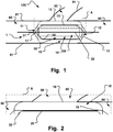
- a medical device 1 is shown.
- the medical device is adapted to temporary occlude a fluid flow from a main lumen 80 of a body into a branch lumen 90 at a branch site 100 inside the body, or to close another type of opening or weakening 85 in a tissue wall 81 surrounding the lumen.
- Main lumen 80 has a tissue wall 81 and branch lumen 90 has a tissue wall 91.
- the opening 85 of the branch lumen 90 into the main lumen 80 is also called ostium.
- the body is a human or animal body, e.g. a body of a mammal.
- the medical device is collapsible and expandable for transluminal delivery to and from the branch site 100.
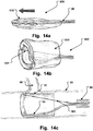
- Fig. 1 the device 1 is shown in its expanded state, deployed and released put of a delivery catheter, and positioned at a branch lumen 90 and preventing a fluid flow from the main 80 into the side branch lumen 90.
- the device 1 remains affixed to the delivery unit via a wire 45. That means the side branch lumen 90 is fluidly disconnected from the main lumen 80. Communication or a flow of fluid through the ostium into the side branch lumen is blocked. This is done in an effective way.
- Positioning is made in accordance with medical procedures to which the medical practitioner is well acquainted, which will be described further below.
- the medical device 1 comprises an aggregate of a first inflatable balloon 10 and a support structure 20.
- the first inflatable balloon 10 has a longitudinal dimension that extends substantially between a proximal end portion 11 and a distal end portion 12 thereof.
- the first balloon 10 comprises a radially arranged inner wall 15 and a radially outer wall 16 at a radial distance therebetween when the first balloon 1 is in an inflated state, as shown in Fig. 1 .
- the outer wall 16 may be adjacent the support structure, besides inner wall 15.
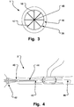
- the inner wall 15 surrounds or encircles an inner hollow 19 configured to provide a longitudinal fluid flow passage through the inner hollow 19, see for instance the arrows illustration such a flow in Fig. 4 .
- the first balloon 10 may be inflated via one or more inflation lumen 17.
- the aggregate comprises at least one support structure 20.
- the support structure 20 is illustrated as a tubular member.
- Embodiments of the medical device comprise at least one collapsible and expandable support structure 20, longitudinally arranged at least partly between the proximal end 11 and distal end 12 of the first balloon 10, and radially arranged at the inner wall 15 thereof.
- the support structure 20 may also extend beyond the ends 11, 12 of the balloon, see e.g. Fig. 11b .
- the support structure 20 when in an expanded state, supports a patency of the inner hollow 19 of the first balloon 10 in the inflated state thereof.
- the first balloon 10 is substantially kept in a desired substantially toroid or doughnut shape, independent of the anatomical surrounding situation. Furthermore, the passage through the aggregate, allowing fluid flow through the first balloon 10 at the branch site 100, is reliably upheld. Movements of the body at the branch site 100, e.g. by vessel contractions or pulsatile flows of fluid in the main lumen 80, do substantially not influence the sealing effect of the aggregate, maintaining the cut-off communication at the opening of the branch vessel.
- the support structure 20 also provides a counter force to the elasticity of a wall 81 of a lumen in which the aggregate is positioned and inflated.
- a counter force to an inward movement of the inner balloon wall 15 is provided by the support structure, maintaining the lumen open to a large extent, which allows for a low profile of the balloon 10 cushion in relation to the entire diameter of the body lumen.
- a more reliable fixed positioning in the lumen is provided as the balloon is pressed between the vessel, acting inwards, and the support structure, and acting as counter point and/or outwards.
- the sealing at the tissue wall is effectively improved by this force provided by the support structure 20.
- the tissue of the lumen wall is treated gently and not injured.
- the cushion effect of the inflated balloon 10, having an inherent flexibility of its gently inflated toroid lumen, allows for an advantageous appositioning of the lumen wall.
- Inflation pressures of the first balloon are chosen, such that the balloon is inflated such that the suspension effect of the inflated balloon between the support structure and the lumen wall is provided.
- the first balloon 10 is not inflated to such an extent as to expand the lumen wall such that damages occur in this wall.
- Inflation pressure is provided such that a reliable sealing is provided, which might be verified in real-time, e.g. by fluoroscopy and suitable contrast agents.
- This inflation pressure is magnitudes lower than that needed for conventional angioplasty balloons. Still, the device is reliably kept in position and not washed away. A certain degree of expansion of the tissue wall 81 by the expanded aggregate may be allowed.
- the outer wall 16 of the first balloon is devised for at least partly apposition to an inner wall of the main lumen 80 at the branch site 100. As shown in Fig. 1 , the outer wall is in apposition to the lumen wall proximally and distally of the ostium 85.
- the entire outer wall, or at least a radially outer portion thereof, may be in apposition to the main lumen 80 inner tissue wall surface.
- the radially outer portion may be substantially straight in longitudinal extension of the balloon 10.
- a fluid passage through the main lumen 80 is kept open and a communication through the opening, e.g. as a passage of fluid, into the branch lumen 90 is substantially sealed when the device 1 is deployed and expanded and inflated at the branch site 100.
- the device 1 is anchored reliable at the branch site in the main lumen 80 against the wall of the lumen and by remaining affixed to the delivery system, e.g. a delivery wire, catheter, etc.
- the device When the device is given a suitable longitudinal dimension, it may cover a plurality of openings and thus occlude flow into these openings. This may be advantageous, if several openings are positioned at different radial and longitudinal positions of the lumen. Also, in case the lumen wall is sensitive, e.g. there is a risk of lumen wall rupture, a lumen wall weakening, or a plurality of smaller openings, these conditions are advantageously sealed off by embodiments of the invention, including devices having long longitudinal extensions, or other embodiments, as e.g. shown and described with reference to Fig. 5 .
- the balloon has a longer longitudinal extension than the opening or weakening of the tissue wall 81.
- the inner wall 15 and outer wall 16 are coaxially arranged in relation to each other and the inner hollow 19 is centrally arranged within the inner wall 15 and within the support structure 19, when expanded.
- the support structure 20 is a tubular support structure comprising a generally cylindrical body arranged at an inner wall boundary of the first balloon 10 to the hollow center 19. The support structure 20 is positioned coaxially with the first balloon 10 in the hollow center 19 at the inner boundary of the first balloon 10.
- the support structure 20 may be self expandable.
- the support structure is restricted to expand during delivery to the branch site or opening, e.g. by means of a catheter sheath 44 ( Fig. 4 ).
- the self expandable support structure 20 radially expands, together with the first balloon 10 getting inflated, whereby the first balloon is expanded, and the aggregate is positioned at the opening 85, as e.g. shown in Fig. 1 .
- the self expanded, relaxed or natural diameter of the support structure 20 is larger than the diameter of the inner wall 15 of the balloon in its relaxed or natural diameter when inflated with the necessary inflation pressure to obtain a reliable sealing of the opening 85.
- the self expanded, relaxed or natural diameter of the support structure 20 may even be larger than the outer wall 16 diameter or the natural diameter of lumen 80. In this manner, a outwardly oriented force 151 is permanently present during the temporary sealing of the opening 85.
- the expanded state of the aggregate is shown in cross section in Fig. 10a .
- the support structure 20 may be affixed to the inner wall 15 by suitable fixation units, such as glue, threads, anchoring elements, etc.
- suitable fixation units such as glue, threads, anchoring elements, etc.
- the support structure may also be provided separate from the first balloon 10 and releasably affixed to the first balloon 10 inner wall by an active radially outwardly oriented expansion force in the released state.
- the support structure 20 is not self expandable and needs to be expanded by an expansion unit to an expanded state 20a, e.g. by means of a delivery unit.
- the support structure 20 is for instance balloon expandable and/or expandable by other active expansion units.
- a second balloon 30 is provided that is adapted to expand the tubular support structure 20, and is at least partly arranged inside the inner hollow 19 of the first balloon 10.
- the second balloon 30 is longitudinally at least extending between the proximal end and distal end of the support structure 20, such that the entire support structure 20 is expanded upon inflation of the second balloon 30, see Fig. 2 .
- the second balloon 30 may be deflated and retracted upon expansion of the support structure 20.
- the second balloon 30 may also have an inner hollow 39.
- the inner hollow 39 allows for a fluid flow therethrough when the second balloon is inflated. In this manner, the second balloon 30 may be left in place during a time of occlusion of the branch lumen 90. Also, during inflation, the main fluid flow is not entirely reduced.
- inflation lumina are provided for inflation of the balloons.
- a first inflation lumen 17 is associated with the first balloon 10 and a second inflation lumen 37 is associated with the second balloon 30.
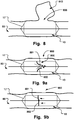
- Fig. 3 is a cross sectional view in longitudinal direction of the medical occlusion device 1 showing the inflation lumen 17 extending from a catheter shaft 45.
- Support webs 18 are provided for attaching the support structure 20 to the catheter shaft 45, or central delivery wire, and/or an active expansion unit.
- the support webs may be arranged as leading support webs 18.
- the support webs 18 may be integral with the support structure 20, such as integral with a mesh, optionally extending longitudinally beyond the balloon 10, as shown in Figs. 11b or 12 .
- further support webs may be provided inside the inner hollow 19, and at the trailing end of the medical device 1.
- Leading support webs 18 facilitate collapsing the medical device 1 and re-inserting it into the sheath 44 for withdrawing the medical device from the branch site 100 and out of the body.
- the webs may constitute a filter unit for the fluid flow through the main lumen 80 when the aggregate is in place at the opening 85.
- the filter unit may be a blood clot filter.
- a degree of filtering may be determined by the pick and pitch of a braiding, or a radial and/or longitudinal number of webs, of the support structure 20.
- Trailing webs facilitate insertion of the aggregate into a catheter, which is automatically collapsed when pushed into a proximal opening of the catheter lumen.
- the first and second inflation lumina 17, 37 may be arranged to be in fluid communication with each other. In these embodiments, simultaneous inflation of both the first and second balloon is provided. This may provide an easy installation of the medical device 1 at the branch site 100. The medical practitioner only needs to take care of a single inflation step, whereupon the medical device is securely positioned.
- first and second inflation lumina 17, 37 are not in fluid communication with each other. Individual inflation of the first and second balloon is provided. This embodiment may be preferred in certain anatomical situations, where e.g. an initial positioning of the device is made by inflating the first balloon 10, when the support structure is not self expanding. Subsequently, the second balloon 30 is inflated to expand the support structure 20, and to thus securely anchor the medical device 1 and to provide a support for the inner hollow 19 for fluid communication, as well as sealing of the opening 85. Further, the second balloon 30 may then be withdrawn, which leaves a large diameter open lumen through the aggregate for fluid flow. This is in particular of interest for high-flow applications, e.g. close to the heart output in order to maintain cardiac output.
- the second balloon's inner hollow 39 provides a longitudinal through-passage through the medical device 1 when positioned at the branch site 100.
- the second balloon 30 may be arranged to be deflated and retracted upon expanding the support structure 20.
- the diameter of the through-passage substantially corresponds to the diameter of the inner hollow 19, as the support structure is substantially flat compared to the radial extension of the inner hollow 19.
- the through-flow capacity of the through passage is enhanced in comparison to having the second balloon 30 arranged therein and determining the diameter of the through passage by its inner hollow 39.
- the second balloon 30 may have a section with larger diameter in at least one end portion thereof for expanding the support structure in sections with different diameters.
- the support structure 20 is at least partly attached to the inner wall 15 of the first balloon 10 on an outside wall surface of inner wall 15 at the inner hollow 19 side.
- the support structure 20 may alternatively, or in addition be integral with the inner wall 15 of the first balloon 10.
- the support structure 20 may in particular be molded together with the inner wall 15.
- the support structure 20 is attached to the inner wall 15 of the first balloon 10 on an inside wall surface thereof, inside the first balloon.
- improved fluid flow in the inner hollow may be provided.
- the support structure 20 will, when expanded, the common radial position when in an equilibrium with the counter acting inflation force of inner wall 15 upon inflation of the first balloon 10.
- the retractable sheath may be omitted.
- a restriction of the support structure 20 in its collapsed configuration is not necessary.
- the expansion unit may comprise a pusher or pushing sheath that is arranged to suitably actively expand the non-self-expandable support structure 20.
- the expansion unit may comprise arms or a resiliently expandable structure that pushes the support structure 20 from its interior outwardly to an expanded, open configuration, where it supports the first balloon and provides the actions and functions described herein.
- the expansion unit may be the second balloon 30 described above.
- first balloon 10 may support the expansion of the support structure 20 during it is being inflated.
- the first balloon 10 may be inflated before, after or during expansion of the support structure 20, upon release from the delivery catheter at site 100.
- the first balloon has a maximum inflation pressure, as will be explained below with reference to Fig. 10a .
- the maximum inflation pressure is suitably below a burst pressure of the balloon 10.
- the first balloon 10 is inflated to a pressure less than this maximum inflation pressure, at least during positioning at the body site and/or during the entire occlusion/sealing phase.
- the first balloon 10 may be especially tissue friendly positioned in the lumen.
- a partly inflated first balloon 10 provides in particular a soft cushion effect for special soft apposition to wall tissue of the lumen in which it is expanded.
- the first balloon 10 may be partly or not at all inflated during expansion of the support structure. It may be folded, bend or doubled for a compact delivery arrangement.
- the first balloon 10 is for instance not inflated during expansion of the support structure 20. In this manner the support structure 20 is expanded to a diameter substantially equal to the inner diameter of the lumen 81. Inflation of the first balloon upon expansion of the support structure thus ensures that the first balloon is expanded to a larger diameter than the inner diameter of the lumen 81.
- the inflation degree of first balloon in relation to the maximum inflation pressure provides a selectable degree of tissue anchoring of the medical device at the body site.
- the expanded support structure 20 is configured to bear against the force of the first balloon directed inwardly when inflated.
- the outward expansion of the first balloon is ensured while preventing that the balloon is sucked into the opening 85.
- a certain degree of radial flexibility to a smaller diameter may occur in equilibrium, see Fig. 10a .
- the support structure 20 When expanded, the support structure 20 may be releasably locked in its expanded configuration during the time of occlusion. This may for instance be provided by a snap or click mechanism. Bistability of the support structure between two points of minimum energy (collapsed and expanded) may be provided alternatively, or in addition to the locking functionality.
- the support structure 20 may be a tubular structure that comprises a mesh of wires. Alternatively, or in addition, it comprises a pattern of struts and connectors, such as a zigzag pattern, as known from stent technology.
- a stent includes a cylindrical frame consisting of a series of helical winds containing a pattern of alternating zigzag bends.
- the frame may be made of resilient wire or from a piece of laser cut hypo tubing.
- a method of making such a stent is disclosed, which is incorporated herein by reference in its entirety.
- the laser cut stent for transluminal delivery has windows in its cylindrical wall, the windows giving the stent enhanced flexibility during delivery along said lumen.
- the method of making such a stent involves removing from the wall of a tube enough material to leave the tube wall penetrated in a multiplicity of separate cut lines, in a pattern which permits the tube to expand.
- the tube is then expanded and then a plurality of tube wall scrap portions are removed from the tube wall between adjacent cut lines, thereby to introduce a plurality of spacings between adjacent stenting zones of the tube wall surface, these remaining after compression of the tube to a configuration to allow it to be advanced along a tortuous bodily lumen.
- the material of the tube is a shape memory alloy and the tube is for a self-expanding stent.
- stents were hitherto always positioned on the outside of an inflatable balloon for expansion and permanent implantation. Stents are devised for apposition to vessel tissue.
- the present support structure 20 is devised for apposition to an inner balloon wall, supporting the balloon, and having a toroid balloon sealing cushion between the support structure 20 and the lumen inner wall tissue.
- the support structure may comprise a plurality of radial support webs 18 in addition or alternatively to the tubular structure disclosed herein.
- the webs 18 are arranged from a catheter shaft 45 or a delivery wire. Webs 18 may for instance be pre-tensioned to provide a radially outwardly directed force supporting the first balloon at the branch site 100.
- a length of the support structure 20 and a length of the second balloon 30, if arranged therein, is in an embodiment larger than a length of the longitudinal dimension of the first balloon 10. This is illustrated in Figs. 6 and 11b , where longitudinal extensions 21, 22 of the support structure 20 are shown.
- the first balloon 10 shown in Fig. 6 is positioned at an abnormal lumen opening 900.
- the abnormal lumen opening may for instance be a rupture, hole, damage, aperture or other opening.
- the abnormal opening necessitates a medical measure, e.g. a surgical repair or installation of a graft.
- the device 200 provides temporary occlusion of a fluid flow out of the main lumen through the abnormal opening. During the temporary occlusion time, a medical procedure may be performed in order to remedy the abnormal opening. Upon completion of the medical procedure, the abnormal opening is closed and a leak of fluid through the wall of the main lumen will no longer occur. The temporary occlusion device 200 is then removed from the temporary occlusion site.
- FIG. 8 Another example is the occlusion of an aneurysm 910, as illustrated in Fig. 8 .
- a fluid communication or flow from the main lumen into the aneurysm is stopped, in a similar manner as described above with reference to Fig. 6 .
- a rupture of the aneurysm has not yet occurred and the vessel wall is intact but weakened.
- a pressure relief is provided by the temporary communication cut off of occlusion device 200.
- the opening or abnormal opening in the context of the present application is usually a lateral opening in the wall of the lumen.
- proximal end and/or the distal end of the support structure 20 is constructed such that it is expandable to a greater outer diameter than an inner diameter of the inner hollow 19 of the first balloon 10.
- the extensions 21, 22 at the proximal end and/or distal end of the support structure 20 may be outwardly flared towards the outer wall of the first balloon 10 and oriented away from the proximal end and/or distal end of the first balloon 10, respectively.
- a fluid guide is provided that advantageously minimizes turbulences of fluid flow in the main lumen 80 through the medical device 1. Further, sealing is improved.
- the medical device 1 is provided with a support structure 20 that comprises at least a proximal extension 21 extending proximally longitudinally beyond the proximal end 11 of the first balloon 10.
- the proximal extension 21 may comprise a cover or fluid tight layer or coating for tissue friendly contacting an inner tissue wall of the main lumen 80 proximally the first balloon 10.
- a fluid guide into the inner hollow 19 of the first balloon 10 is provided upon expansion of the support structure 20 and its proximal extension 21.
- the support structure 20 comprises in embodiments a distal extension 22 extending distally longitudinally beyond the distal end of the first balloon.
- the distal extension may comprise a cover or fluid tight layer or coating for tissue friendly contacting an inner tissue wall of the main lumen 80 distally the first balloon 10, such that a fluid guide out of and/or into the inner hollow of the first balloon is provided upon expansion of the support structure 20 and its distal extension 22.
- One or more of the extensions 21, 22 may be provided as a sealing flange.
- the sealing flange may be made of a suitable fabric.
- the longitudinal extensions of the support structure 20 may have a heat set shape to an extension of an outer diameter of the first balloon.
- the longitudinal extension of the support structure is at least as large as the diameter of the opening 85.
- the first balloon has a balloon body of elongate torus shape, when inflated.
- the outer wall 15 of the first balloon 10 is at least partly devised for soft tissue apposition to the inner wall of the main lumen 80 at a first portion of the outer wall, such that the device is configured to securely and sealingly engage the main lumen.
- the outer wall is preferably thin walled, providing a tissue friendly apposition to the tissue wall.
- the outer wall 16 and the inner wall 15 of the first balloon 10 may have sections of different rigidity.
- the different rigidity is for instance provided by different wall thicknesses of the sections of the outer wall and the inner wall.
- the outer wall 16 of the first balloon 10 has e.g. proximal and distal end portions that have a wall thickness that is larger than a wall thickness at the central elongate portion of the outer wall 16. Thicker portions may advantageously be oriented towards the opening in the delivered state. In this manner, patency of the longitudinal channel of the medical device 1 through the main lumen 80 is reliably closed off, providing an occlusion of the side branch vessel 90.
- a ratio of a maximum outer diameter of the first balloon 10 in relation to maintained passage lumen diameter of the inner hollow 19 is in the range of 40% to 90%.
- the ratio may be 75% to 90%, such as 80%, 85% or 90%.
- Such high ratios are possible thanks to the natural expanded diameter of the support structure 20 being larger than the natural inflated inner diameter of the balloon 10.
- the medical device 1 may comprise radiopaque markers.
- the first balloon 10 is adapted to be inflated with radiopaque material. This facilitates positioning of the medical device 1 at the branch site 100 under fluoroscopy.
- the lumina are in specific embodiments blood vessels.
- the outer wall 15 is configured to be arranged to sealingly cover an ostium of the branch lumen 90 at the branch site 100.
- the first balloon 10 is adapted to be inflated over an extended period of time for occluding the ostium to the side branch lumen, e.g. during a surgery of an organ supplied with blood by the side branch vessel 90.
- the aggregate of a first balloon 10 and inner support structure 20 is re-collapsible after expansion, such that the device is transluminally removable from the branch site and out of the body upon a time of occlusion of the branch lumen 90.
- the outer diameter of the first balloon 10 may be chosen slightly larger than the inner diameter of the main lumen 80. In this manner a reliable positioning of the medical device 1 in the main lumen 80 is provided, while not harming any tissue thereof.
- Fig. 10a is a cross sectional view through a medical occlusion device at an occlusion site in a body lumen.
- Various forces acting in the expanded state of the aggregate when positioned at an opening 85 are illustrated by arrows 150-153.
- a first force acts radially inwards and is caused by the pressurized inner wall 15 of the balloon 10.
- a second force 151 caused by the expansion force of the support structure 20 counteracts this first force 150.
- the support structure is not fully expanded.
- the outer diameter of the structure 20 at its relaxed state is larger than the inner diameter of the balloon 10 at inner wall 15 when inflated and without an acting counter force.
- a wire cage may be actively expanded, an inner balloon having a passageway of its own may be inflated inside the lumen 80, webs may resiliently push the inner wall 15 radially outwards, etc.
- the dotted line 20a illustrates a possible position of the structure 20 when fully expanded without counter force.
- the outwardly oriented expansion force 151 of the support structure 20 is larger than the inwardly oriented inflation force 150.
- the support structure will be tensioned against the wall 15 and may not be affixed to the latter, allowing for a relative movement of the two latter relative each other, whereby deployment, expansion, and retrieval is facilitated due to reduced forces.
- the lumen wall 81 resiliently pushes with a force 153 against the radially outwardly anchoring force 152 of the outer wall 16 of the inflated balloon 15.
- Anchoring force 152 of the inflated balloon 10 is larger than the lumen force 152.
- the outward inflation force 152 is only slightly larger than inward tissue force 153.
- the medical device 1 may be comprised in a medical system 2 devised for temporary closure of a branch lumen 90 of a main lumen 80 of a body into the branch lumen 90 at a branch site 100 inside the body.
- the system 2 comprises, as illustrated in Figures 4 , 5 and 11a , at least one medical device 1 a catheter 40 comprising a catheter shaft 45 and a catheter sheath 44.
- the aggregate of the medical device 1 is associated with the catheter shaft 45 at a distal end portion thereof.
- the catheter sheath 44 is arranged to restrict expansion of the aggregate when positioned in the catheter sheath 44.
- the catheter sheath 44 is retractable from the catheter shaft 45 to allow expansion of the aggregate at the branch site 100 for the temporary closure of the side branch vessel.
- the catheter shaft 45 comprises a guidewire lumen for passage of a guidewire 46 to position the catheter 40 within the main vessel 80 at the branch site 100, and at least one inflation lumen for inflating at least the first balloon 10.
- the system 2 furthermore comprises the guidewire 46 arranged in the guidewire lumen of the catheter shaft 45.
- Materials for making the balloons can be polyvinyl-chloride (PVe), cross-linked polyethylene (PE), polyester (PET), polyethylene terephthalate, Nylon, and others.
- PVe polyvinyl-chloride
- PET polyester
- PET polyethylene terephthalate
- Nylon polyethylene terephthalate
- polytetrafluoroethylene PTFE commercially available as Goretex®, is suitable as a balloon material.
- the medical device is in embodiments intended for usage mainly in vascular surgery in operating rooms with access to fluoroscopy imaging facilities (hybrid OR).
- the medical device may be used in both acute and elective surgery.
- the medical device may be positioned in the peripheral vessel as an initial step of the intervention.
- the device is thus, amongst others, useful for passive interventions, which do not need acute measures.
- Figs. 9a and 9b are schematic illustrations of a medical occlusion device of the type described above having a unidirectional flow direction unit 800 in an inner hollow thereof.
- the medical device is provided with check valve functionality.
- a plurality of valve flaps 801, 802 provide the check valve function.
- the unidirectional flow direction unit 800 may comprise a single valve flap, e.g. a circular valve flap having a central fixation at the guidewire or catheter shaft 45.
- valve seat may be provided in a separate structure.
- valve seat my be provided as a annular ring of the support structure 20, protruding into the inner hollow.
- Self expandable or balloon expandable transcatheter valve assemblies may be positioned inside the support structure 20.
- the support structure 20 may be an outer part of a valve assembly for transcatheter delivery.
- the unidirectional flow direction unit 800 may be an improved valve of the type of minimally-invasive heart valves, such as disclosed in US6454799 of Edwards Lifesciences, prosthetic valves for transluminal delivery, such as disclosed in US7018406 of Corevalve Inc., which are incorporated herein in their entirety for all purposes.
- these known permanent valve assemblies are suitably modified for the present invention to be re-collapsible, and surrounded by an inflatable balloon 10.
- a medical device having a unidirectional flow direction unit 800 and a surrounding inflatable balloon 10, and associated support structure 20, is provided.
- Applications for such a medical device are for instance medical procedures, where temporary creation of a temporary unidirectional flow is desired.
- the medical device may provide a simultaneous occlusion of an abnormal opening in the lumen wall.
- An example for such a medical procedure comprises positioning the medical device in the venous system.
- the medical device may be positioned at a venous rupture in the venous system.
- a venous rupture may for instance occur in peripheral or central veins and needs medical treatment.
- Another example is the positioning of temporary heart valves.
- a method of deploying the medical device 1 at a branch site 100 by means of a medical system 2 as described above, will be given further below. Positioning at other openings than ostia to branch vessels is made correspondingly.
- FIG. 10b A medical device having an oval cross section is shown in Fig. 10b .
- a fluid flow is also provided along the volume between the outer wall 16 and the lumen wall as illustrated by the hatched sections in the Fig.
- the radial orientation of device in relation to the opening/weakening 85 provides a reliable sealing thereof, while the potential maximum fluid flow is increased by multiple flow passages.
- a risk of obstruction of the fluid flow in the main channel is reduced as redundancy of flow channels is provided.
- the additional flow channel 80a is not restricted, in contrast to the main lumen where a delivery unit is centrally arranged and webs or inflation lumen extend radially.
- a kit 3 comprises at least two medical devices 1 of the type disclosed above. As illustrated in Fig. 5 , a proximal medical device 1a and a distal medical device 1b are comprised in a kit 3.
- the aggregates of the medical devices 1a, 1b are spaced apart from each other and interconnected to each other by a fluid leakage tight interconnection unit 50 adapted to provide a through-flow of fluid between inner hollows of first balloons of the medical devices 1a, 1b.
- the interconnection unit may extend past one or more openings in the lumen wall.
- the interconnection unit 50 is a tubular interconnection unit having a fluid tight tubular wall 51 between a proximal end and a distal end of the tubular interconnection unit.
- the tubular wall may be made of a membrane material. Suitable materials comprise polytetrafluoroethylene PTFE, commercially available as GoreTex®. Alternatively, or in addition, graft material may be provided that is reinforced. In this manner, the unit 50 is adapted to withstand radial outward expansion beyond a tubular shape of a desired maximum diameter. This diameter is for instance the outer diameter of the balloon 10, or the natural inner diameter of the main body lumen.
- the proximal end of the tubular wall 51 is connected to a distal opening of the inner hollow 19 of the proximal medical device 1a.
- the distal end of the tubular wall 51 is connected to a proximal opening of the inner hollow of the distal medical device 1b.
- a fluid channel between the inner hollows of the two medical devices 1a, 1b is provided.
- the medical devices 1a, 1b upon inflation of first balloons thereof, provide a fluid tight positioning thereof against an inner wall of the main lumen and only allow a fluid flow through the inner hollow thereof.
- a fluid flow into the opening 85 or branch vessel 90 is effectively prevented.
- the tubular interconnection unit may have other cross sections than circular, e.g. oval, substantially flat, rectangular, etc.
- the proximal medical device 1a is adapted to be positioned proximally of an ostium of the branch lumen into the main lumen.
- the distal medical device 1b is adapted to be positioned distally of the ostium.
- the tubular wall 51 is non-elastic and flexible and adapted to be arranged along the ostium, in the main lumen. It is preferably arranged at a distance from the ostium, without contacting tissue of the main lumen, ostium or branch lumen, as illustrated in Fig. 5 .
- the outer diameter of the tubular wall 51 is preferably smaller than the natural inner diameter of the body lumen. Thus, it is avoided that debris is created, which can be flushed into the branch vessel upon removal of the medical devices.
- the tubular wall 51 may comprise a reinforcement structure, such that pressure fluctuations therein substantially do not alter the tubular shape.
- a longitudinal substantially straight extension may thus advantageously be provided between the devices 1a and 1b.
- Figs. 11a and 11b are side views of an embodiment of a medical occlusion device.
- a catheter 40 with a sheath 44 is shown having an aggregate of a support structure 20 and a balloon 10.
- This stent 20 is mounted to two extrusions.
- a balloon 10 with a separate extrusion line is mounted to the stent 20 as well.
- Fig. 11a shows the catheter 40 with a short sheath 44.
- Fig. 11b shows the tip section of this assembly. The stent and balloon are shown in the expanded and inflated state.
- the stent 20 By advancing the first extrusion 310 into the second extrusion 320 at the proximal end of the catheter 40, the stent 20 is straightened.
- the stent 20 can be fixed in this position by screwing the male Luer lock 330 at the first extrusion 310 to the female Luer which is mounted to the second extrusion 320.
- a guide wire may be inserted as a supporting wire into the guide wire lumen, i.e. the second extrusion 320.
- the stent 20 and the balloon 10 can be pulled back into the sheath tip.
- the catheter 40 is ready for insertion into the body.
- the latter are advanced by pushing all the extrusions 310, 320 into the sheath 44.
- the Luer lock 330 is unlocked to expand the stent 20 as soon as the stent 20 is in the correct position.
- the vessel By filling the balloon 10 with e.g. air or saline, side arms of the vessel are blocked.
- the maximal inflation volume that is pressed into the balloon is previously defined to not exceed a threshold that may burst the balloon or collapse the sent. Otherwise the vessel could be blocked.
- Fig 12 is a side view of an embodiment of a medical occlusion device.
- a wire 45 manipulated from the proximal end of the catheter used for delivery of the medical device may provide the active expansion, e.g. by a relative movement of the support structure to the catheter sheath while being affixed to the latter in at least one point. Expanding a cage of a wire mesh initiated by a central control wire is an example for such a wire manipulation determining the degree of expansion of the support structure, like above with reference to Fig. 11b .
- the aggregate 400 of balloon and support structure is elongated and collapsed by pushing the delivery wire distally.
- the wire may be locked in this position for delivery.
- the aggregate expands to its natural form thanks to the elasticity of the support structure.
- the delivery wire is further drawn back in a relative movement to the catheter, thus actively further expanding the aggregate radially in the body lumen at the site of the opening or weakening in the lumen wall.
- the balloon is then inflated as described above.
- the end sections of the balloon are cut in an oblique angle in order to facilitate insertion into the catheter and re-insertion into the latter upon withdrawal.
- the balloon is made of two sheets that are welded to each other at the edges.
- the occlusion device is neither released from the catheter nor released from the delivery unit; it remains affixed thereto at all times.
- the device is positioned at the opening and then released from catheter in that position, and expanded and inflated into position, without further longitudinal re-location.
- the catheter sheath may e.g. be withdrawn in that position.
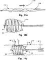
- Figs. 13a, 13b, 13c are two lateral views and a cross sectional view of further medical occlusion device 500 in an extended delivery shape, an expanded shape, and inserted at an opening in a body lumen, respectively.
- the device is brought from the relaxed state ( Fig. 13a ) to the expanded helical shape by drawing a tether line 501 in the direction of the arrow in Fig. 13a .
- the opening When positioned at the opening, e.g. of a side lumen, the opening is blocked.
- This embodiment has a small collapsed diameter and is in particular deliverable through narrow passages for delivery to the opening site.
- a soft, sponge like structure may be used instead of a balloon 10.
- the structure may swell when it comes into contact with the body fluid in the lumen and thus increase the sealing effect.
- Figs. 14a, 14b, 14c are two lateral views and a cross sectional view of further medical occlusion device 600 in an extended delivery shape, an expanded shape, and inserted at an opening in a body lumen, respectively.
- the device 600 is if the windpipe design and is brought from the delivery state ( Fig. 14a ) to the expanded shape by pushing a tether line 501 in the direction of the arrow in Fig. 14a .
- a fluid tight fabric 610 is provided. This embodiment has a particular high through flow as the proximal end of the fabric has the same diameter as the distal end (which is oriented against the flow direction). The distal end has a soft cushion or inflatable balloon to increase sealing.
- Figs. 15a, 15b, 15c are two lateral views and a cross sectional view of further medical occlusion device 700 in an extended delivery shape, an expanded shape, and inserted at an opening in a body lumen, respectively.
- the device 700 is brought from the relaxed state ( Fig. 15a ) to the expanded helical shape by drawing a tether line 501 in the direction of the arrow in Fig. 15a .
- a fluid tight fabric 610 is provided.
Claims (15)
- Eine medizinische Vorrichtung (1) zur vorübergehenden Abschottung der Kommunikation zwischen einem hohen Hauptlumenstrom (80) eines Körpers durch eine Öffnung (85) in einer Wand (81) des vorerwähnten Hauptlumens an einer Stelle (100) innerhalb des Körpers, wobei die vorerwähnte medizinische Vorrichtung ein Abgabesystem aufweist und die vorerwähnte medizinische Vorrichtung (1) proximal am vorerwähnten Abgabesystem befestigt ist und bleibt, für eine transluminale Abgabe zur und von der vorerwähnten Stelle (100) ausdehnbar und komprimierbar ist und folgende Teile aufweist:a) einen ersten aufblasbaren Ballon (10) länglicher Ausdehnung, der sich hauptsächlich zwischen einem proximalen und einem distalen Ende erstreckt, mit einer radialen Innenwand (15) und einer radialen Außenwand (16) in einer dazwischenliegenden radialen Distanz, wenn der vorerwähnte erste Ballon aufgeblasen ist, wobei der vorerwähnte Ballon (10) an der vorerwähnten Innenwand (15) einen natürlichen inneren erweiterten Durchmesser aufweist und einen inneren Hohlraum (19) umgibt, um einen längsgerichteten Flüssigkeitsstrom durch den vorerwähnten inneren Hohlraum (19) entlang des vorerwähnten Hauptlumens (80) und durch die vorerwähnte Öffnung (85) zu erzeugen, und wobei im vorerwähnten aufgeblasenen Zustand die vorerwähnte Außenwand (16) des vorerwähnten ersten Ballons zumindest teilweise an der vorerwähnten Wand (81) des vorerwähnten Hauptlumens (80) an der vorerwähnten Stelle (100) anlagert undb) mindestens einer ausdehnbaren und komprimierbaren Tragstruktur (20) mit einem erweiterten Durchmesser, der länglich vom vorerwähnten proximalen bis zum distalen Ende des vorerwähnten ersten Ballons (10) und radial an der vorerwähnten Innenwand (15) angeordnet ist, wobei die vorerwähnte Tragstruktur im ausgedehnten Zustand die Durchgängigkeit des vorerwähnten inneren Hohlraums (19) des vorerwähnten ersten Ballons (10) zumindest in dessen aufgeblasenem Zustand unterstützt,dadurch gekennzeichnet, dass
der vorerwähnte erweiterte Durchmesser größer als der vorerwähnte innere erweiterte Durchmesser ist und die vorerwähnte radiale Distanz erheblich kleiner als der vorerwähnte innere erweiterte Durchmesser ist,
so dass die vorerwähnte Vorrichtung (1) hauptsächlich den Durchfluss der vorerwähnten Flüssigkeit durch das vorerwähnte Hauptlumen (80) offen hält und die Kommunikation durch die vorerwähnte Öffnung (85) abschottet, wenn die vorerwähnte Vorrichtung an der vorerwähnten Stelle (100) eingesetzt wird und die vorerwähnte medizinische Vorrichtung keinen Wirkstoffanschluss zur Abgabe eines Wirkstoffs durch die vorerwähnte Öffnung (85) aufweist
und einen zweiten Ballon (30) aufweist, wobei die vorerwähnte Tragstruktur (20) vom vorerwähnten zweiten Ballon (30) erweitert werden kann und letzterer die vorerwähnte schlauchförmige Halterung auf den vorerwähnten erweiterten Durchmesser aufbläst und zumindest teilweise innerhalb des vorerwähnten ersten Ballons angeordnet ist, wobei der vorerwähnte zweite Ballon (30) sich in Längsrichtung zumindest zwischen dem vorerwähnten proximalen und distalen Ende der vorerwähnten Tragstruktur (20) erstreckt. - Die medizinische Vorrichtung gemäß Anspruch 1, wobei ein erstes Aufblaslumen mit dem vorerwähnten ersten Ballon (10) und ein zweites Aufblaslumen mit dem vorerwähnten zweiten Ballon (30) zusammenhängen, wobei die vorerwähnten ersten und zweiten Aufblaslumina miteinander kommunizieren, um den vorerwähnten ersten und zweiten Ballon (30) gleichzeitig aufzublasen oder wobei die vorerwähnten ersten und zweiten Aufblaslumina nicht miteinander kommunizieren, um den vorerwähnten ersten und zweiten Ballon (30) einzeln aufzublasen.
- Die medizinische Vorrichtung gemäß Anspruch 1-2, wobei der vorerwähnte zweite Ballon (30) eine längliche Ausdehnung und einen zentralen Hohlraum aufweist, um einen Durchlass durch den vorerwähnten zentralen Hohlraum des vorerwähnten zweiten Ballons (30) zu gewähren, wenn der vorerwähnte zweite Ballon (30) aufgeblasen ist.
- Die medizinische Vorrichtung gemäß einem der Ansprüche 1-3, wobei der vorerwähnte zweite Ballon (30) so angeordnet ist, dass er beim Aufblasen der vorerwähnten Tragstruktur (20) abgelassen und zusammengezogen werden kann.
- Die medizinische Vorrichtung gemäß einem der Ansprüche 1-4, wobei die vorerwähnte Tragstruktur (20) an der vorerwähnten Innenwand des vorerwähnten ersten Ballons (10) auf einer Außenwandfläche des vorerwähnten inneren Hohlraums angebracht ist.
- Die medizinische Vorrichtung gemäß einem der Ansprüche 1-5, wobei die vorerwähnte Tragstruktur eine Mehrzahl radialer Stütznetze (18) umfasst.
- Die medizinische Vorrichtung gemäß einem der Ansprüche 1-6, wobei eine Länge der vorerwähnten Tragstruktur (20) und eine Länge des vorerwähnten zweiten Ballons (30), wenn er darin angeordnet ist, breiter als eine Länge der vorerwähnten länglichen Erstreckung des vorerwähnten ersten Ballons sind.
- Die medizinische Vorrichtung gemäß Anspruch 7, wobei das vorerwähnte proximale und/oder distale Ende der vorerwähnten Tragstruktur (20) so aufgebaut sind, dass sie auf einen größeren Außendurchmesser erweitert werden kann, von dem ein Teil am vorerwähnten inneren Hohlraum des vorerwähnten ersten Ballons liegt.
- Die medizinische Vorrichtung gemäß Anspruch 8, wobei das vorerwähnte proximale und/oder distale Ende der vorerwähnten Tragstruktur (20) zur vorerwähnten Außenwand des vorerwähnten ersten Ballons (10) hingerichtet und vom vorerwähnten proximalen und/oder distalen Ende des vorerwähnten ersten Ballons (10) abgewendet sind.
- Die medizinische Vorrichtung gemäß einem der Ansprüche 1-9, wobei die Tragstruktur (20) eine proximale und/oder distale Verlängerung aufweist, die radial außen angeordnet ist und sich in einer Distanz von der Längsachse der vorerwähnten Vorrichtung jenseits des proximalen Endes des vorerwähnten ersten Ballons im vorerwähnten ersten erweitertem Zustand befindet.
- Die medizinische Vorrichtung gemäß Anspruch 10, wobei die vorerwähnte proximale und/oder distale Verlängerung eine Abdeckung oder eine dichte Schicht bzw. Beschichtung für die schonende Berührung einer inneren Gewebewand des vorerwähnten Hauptlumens (80) proximal zum vorerwähnten ersten Ballon aufweisen, so dass eine Flüssigkeit bei Ausdehnung der vorerwähnten Tragstruktur (20) in den vorerwähnten inneren Hohlraum des vorerwähnten ersten Ballons (10) geleitet wird.
- Die medizinische Vorrichtung gemäß einem der Ansprüche 1-11, wobei die vorerwähnte Baugruppe bei Ausdehnung radial flexibel ist.
- Die medizinische Vorrichtung gemäß einem der Ansprüche 1-11, wobei die vorerwähnte Vorrichtung röntgendichte Marker aufweist und/oder wobei der vorerwähnte Ballon mit röntgendichtem Material aufgeblasen werden kann oder wobei der vorerwähnte Ballon im aufgeblasenen Zustand mit röntgendichtem Material gefüllt wird.
- Die medizinische Vorrichtung gemäß einem der Ansprüche 1-13, wobei eine unidirektionale Flusseinheit (800) im vorerwähnten inneren Hohlraum angeordnet ist.
- Ein Set (3) mit mindestens zwei medizinischen Vorrichtungen samt Baugruppen nach einem der Ansprüche 1-14, wobei besagte Baugruppen räumlich getrennt und durch eine auslaufsichere Verbindungseinheit (50) miteinander verbunden sind und letztere für den Durchfluss einer Flüssigkeit zwischen den inneren Hohlräumen der ersten Ballons der vorerwähnten medizinischen Vorrichtungen vorgesehen ist.
Applications Claiming Priority (3)
| Application Number | Priority Date | Filing Date | Title |
|---|---|---|---|
| SE0850015 | 2008-09-15 | ||
| US9731508P | 2008-09-16 | 2008-09-16 | |
| PCT/EP2009/061982 WO2010029190A1 (en) | 2008-09-15 | 2009-09-15 | Medical device, method and system for temporary occlusion of an opening in a lumen of a body |
Publications (2)
| Publication Number | Publication Date |
|---|---|
| EP2340076A1 EP2340076A1 (de) | 2011-07-06 |
| EP2340076B1 true EP2340076B1 (de) | 2019-11-06 |
Family
ID=41151829
Family Applications (1)
| Application Number | Title | Priority Date | Filing Date |
|---|---|---|---|
| EP09783062.4A Active EP2340076B1 (de) | 2008-09-15 | 2009-09-15 | Medizinische vorrichtung und system zum temporären verschluss einer öffnung in einem körperlumen |
Country Status (10)
| Country | Link |
|---|---|
| US (2) | US20110172697A1 (de) |
| EP (1) | EP2340076B1 (de) |
| JP (1) | JP5744736B2 (de) |
| CN (1) | CN102256659A (de) |
| AU (1) | AU2009290834B2 (de) |
| CA (1) | CA2824889C (de) |
| IL (1) | IL211751A (de) |
| SG (1) | SG195610A1 (de) |
| WO (1) | WO2010029190A1 (de) |
| ZA (1) | ZA201102788B (de) |
Families Citing this family (62)
| Publication number | Priority date | Publication date | Assignee | Title |
|---|---|---|---|---|
| CA2759746C (en) | 2001-12-05 | 2018-05-22 | Smt Research And Development Ltd. | Endovascular device for entrapment of particulate matter and method for use |
| US9247942B2 (en) * | 2010-06-29 | 2016-02-02 | Artventive Medical Group, Inc. | Reversible tubal contraceptive device |
| WO2012097287A1 (en) * | 2011-01-13 | 2012-07-19 | Innovia Llc | Endoluminal drug applicator and method of treating diseased vessels of the body |
| US20120259401A1 (en) * | 2011-04-08 | 2012-10-11 | Gerrans Lawrence J | Balloon catheter for launching drug delivery device |
| EP2567663A1 (de) * | 2011-09-09 | 2013-03-13 | Occlutech Holding AG | Faltbare medizinische Verschlussvorrichtung, Verfahren und medizinisches System zur Abgabe eines Objekts |
| US10342548B2 (en) * | 2012-01-13 | 2019-07-09 | W. L. Gore & Associates, Inc. | Occlusion devices and methods of their manufacture and use |
| CN102705510A (zh) * | 2012-06-25 | 2012-10-03 | 四川大学 | 一种气球密封方法 |
| US9445828B2 (en) * | 2012-07-05 | 2016-09-20 | Cognition Medical Corp. | Methods, devices, and systems for postconditioning with clot removal |
| DE102012214477A1 (de) * | 2012-08-14 | 2013-09-19 | Siemens Aktiengesellschaft | Vorrichtung zur Durchführung einer Gefäßdilatation |
| JP6347452B2 (ja) * | 2012-10-01 | 2018-06-27 | キューマックス,エルエルシー | 螺旋バルーンカテーテル |
| CN103252013B (zh) * | 2013-06-04 | 2014-10-22 | 南京大学医学院附属鼓楼医院 | 主动脉血管腔介入手术穿刺鞘 |
| AU2014279635A1 (en) * | 2013-06-12 | 2016-01-21 | Keystone Heart Ltd. | Intravascular device with multiple leaflets |
| US9636116B2 (en) | 2013-06-14 | 2017-05-02 | Artventive Medical Group, Inc. | Implantable luminal devices |
| US10149968B2 (en) | 2013-06-14 | 2018-12-11 | Artventive Medical Group, Inc. | Catheter-assisted tumor treatment |
| US9282970B2 (en) * | 2013-09-30 | 2016-03-15 | Covidien Lp | Systems and methods for positioning and compacting a bodily implant |
| US10179248B2 (en) | 2013-12-27 | 2019-01-15 | National University Corporation Gunma University | Implantable spacer |
| CN103750920B (zh) * | 2013-12-31 | 2016-01-20 | 先健科技(深圳)有限公司 | 单向活瓣 |
| WO2015138402A1 (en) * | 2014-03-10 | 2015-09-17 | Trivascular, Inc. | Inflatable occlusion wire-balloon for aortic applications |
| BR112016024049B1 (pt) * | 2014-04-15 | 2023-04-25 | Qmax, Llc | Cateter para uso com um fio guia |
| EP3267950A4 (de) * | 2015-03-11 | 2018-03-21 | Board of Regents of the University of Nebraska | Automatisch abrufbares blutungskontrollsystem |
| WO2016200490A1 (en) | 2015-06-08 | 2016-12-15 | Endovention, Inc. | Method and apparatus for allowing inflation of inflatable elements within medical devices |
| JP6539138B2 (ja) * | 2015-07-16 | 2019-07-03 | 富士システムズ株式会社 | バルーンカテーテル |
| CN108366799B (zh) * | 2015-11-09 | 2023-01-03 | 瑞普医药有限公司 | 用于心血管治疗的血流量减压器 |
| US9550046B1 (en) * | 2016-02-16 | 2017-01-24 | Embolx, Inc. | Balloon catheter and methods of fabrication and use |
| US11565090B2 (en) * | 2016-03-04 | 2023-01-31 | C.R. Bard, Inc. | Perfusion balloon with internal valve |
| US10813644B2 (en) | 2016-04-01 | 2020-10-27 | Artventive Medical Group, Inc. | Occlusive implant and delivery system |
| WO2017199242A1 (en) * | 2016-05-15 | 2017-11-23 | Mazor Robotics Ltd. | Balloon dilator |
| CN110290754A (zh) | 2016-09-01 | 2019-09-27 | 微仙美国有限公司 | 临时主动脉闭塞装置 |
| US11389169B2 (en) | 2016-09-01 | 2022-07-19 | Microvention, Inc. | Temporary aortic occlusion device |
| US10646227B2 (en) | 2016-12-29 | 2020-05-12 | Cerepeutics, LLC | Systems and methods for acute treatment to limit intracerebral hemorrhage growth |
| WO2018237155A1 (en) | 2017-06-23 | 2018-12-27 | Mustapha Jihad A | SYSTEMS AND METHODS FOR PERIPHERAL VASCULAR FILTRATION |
| EP3459469A1 (de) * | 2017-09-23 | 2019-03-27 | Universität Zürich | Medizinische okklusionsvorrichtung |
| WO2019195860A2 (en) | 2018-04-04 | 2019-10-10 | Vdyne, Llc | Devices and methods for anchoring transcatheter heart valve |
| TW202000152A (zh) * | 2018-06-21 | 2020-01-01 | 美商睿諾帛醫學科技股份有限公司 | 多腔球囊導管裝置和方法 |
| EP3820380A1 (de) * | 2018-07-10 | 2021-05-19 | Boston Scientific Scimed, Inc. | Verschlussvorrichtung mit expandierbarem element |
| WO2020033933A1 (en) * | 2018-08-10 | 2020-02-13 | The Foundry, Llc | Vascular treatment devices |
| US20210338998A1 (en) * | 2018-08-30 | 2021-11-04 | Cyberdyne Inc. | Cardiac output support apparatus |
| US11344413B2 (en) | 2018-09-20 | 2022-05-31 | Vdyne, Inc. | Transcatheter deliverable prosthetic heart valves and methods of delivery |
| US10321995B1 (en) | 2018-09-20 | 2019-06-18 | Vdyne, Llc | Orthogonally delivered transcatheter heart valve replacement |
| US11278437B2 (en) | 2018-12-08 | 2022-03-22 | Vdyne, Inc. | Compression capable annular frames for side delivery of transcatheter heart valve replacement |
| US10595994B1 (en) | 2018-09-20 | 2020-03-24 | Vdyne, Llc | Side-delivered transcatheter heart valve replacement |
| US11071627B2 (en) | 2018-10-18 | 2021-07-27 | Vdyne, Inc. | Orthogonally delivered transcatheter heart valve frame for valve in valve prosthesis |
| US11109969B2 (en) | 2018-10-22 | 2021-09-07 | Vdyne, Inc. | Guidewire delivery of transcatheter heart valve |
| DE102018218429A1 (de) * | 2018-10-29 | 2020-04-30 | Heraeus Medical Gmbh | Vorrichtung zur temporären, lokalen Applikation von Fluiden |
| US11077288B2 (en) * | 2018-11-15 | 2021-08-03 | Biosense Webster (Israel) Ltd. | Flushing balloon catheter for observation and removal of clots under vessel bifurcation conditions |
| US11253359B2 (en) | 2018-12-20 | 2022-02-22 | Vdyne, Inc. | Proximal tab for side-delivered transcatheter heart valves and methods of delivery |
| US11185409B2 (en) | 2019-01-26 | 2021-11-30 | Vdyne, Inc. | Collapsible inner flow control component for side-delivered transcatheter heart valve prosthesis |
| US11273032B2 (en) | 2019-01-26 | 2022-03-15 | Vdyne, Inc. | Collapsible inner flow control component for side-deliverable transcatheter heart valve prosthesis |
| AU2020231221A1 (en) | 2019-03-05 | 2021-09-23 | Vdyne, Inc. | Tricuspid regurgitation control devices for orthogonal transcatheter heart valve prosthesis |
| US11173027B2 (en) | 2019-03-14 | 2021-11-16 | Vdyne, Inc. | Side-deliverable transcatheter prosthetic valves and methods for delivering and anchoring the same |
| US11076956B2 (en) | 2019-03-14 | 2021-08-03 | Vdyne, Inc. | Proximal, distal, and anterior anchoring tabs for side-delivered transcatheter mitral valve prosthesis |
| WO2020195581A1 (ja) * | 2019-03-22 | 2020-10-01 | 国立大学法人滋賀医科大学 | 可動型カテーテル |
| EP3965701A4 (de) | 2019-05-04 | 2023-02-15 | Vdyne, Inc. | Cinchvorrichtung und verfahren zum einsatz einer seitlich freigesetzten herzklappenprothese in einem nativen ring |
| CA3152042A1 (en) | 2019-08-20 | 2021-02-25 | Vdyne, Inc. | Delivery and retrieval devices and methods for side-deliverable transcatheter prosthetic valves |
| AU2020337235A1 (en) | 2019-08-26 | 2022-03-24 | Vdyne, Inc. | Side-deliverable transcatheter prosthetic valves and methods for delivering and anchoring the same |
| EP4033999A2 (de) | 2019-09-26 | 2022-08-03 | Universität Zürich | Verschlussvorrichtungen für das linke herzohr |
| DE102019007222A1 (de) * | 2019-10-17 | 2021-04-22 | Xenios Ag | Führungselement für ein steuerbares Gefäßaufweitungssystem |
| US11234813B2 (en) | 2020-01-17 | 2022-02-01 | Vdyne, Inc. | Ventricular stability elements for side-deliverable prosthetic heart valves and methods of delivery |
| CN112274306B (zh) * | 2020-10-08 | 2022-04-05 | 苏州法兰克曼医疗器械有限公司 | 一种快装式用于治疗的胆道内引流支架 |
| US20230157716A1 (en) * | 2021-11-19 | 2023-05-25 | Accumed Radial Systems, Llc | System, apparatus, and method for creating a lumen |
| CN114404787A (zh) * | 2022-01-19 | 2022-04-29 | 深圳市顺美医疗股份有限公司 | 一种颅内球囊以及用于覆盖颅内球囊的方法 |
| TR2022010877A2 (tr) * | 2022-06-30 | 2022-08-22 | Sakarya Ueniversitesi Rektoerluegue | Bi̇r tikali uçlu balon stent kateteri̇ |
Family Cites Families (37)
| Publication number | Priority date | Publication date | Assignee | Title |
|---|---|---|---|---|
| WO1980000007A1 (en) * | 1978-06-02 | 1980-01-10 | A Rockey | Medical sleeve |
| US4944745A (en) | 1988-02-29 | 1990-07-31 | Scimed Life Systems, Inc. | Perfusion balloon catheter |
| US4909252A (en) * | 1988-05-26 | 1990-03-20 | The Regents Of The Univ. Of California | Perfusion balloon catheter |
| US5069662A (en) * | 1988-10-21 | 1991-12-03 | Delcath Systems, Inc. | Cancer treatment |
| US5156620A (en) * | 1991-02-04 | 1992-10-20 | Pigott John P | Intraluminal graft/stent and balloon catheter for insertion thereof |
| US5257974A (en) * | 1992-08-19 | 1993-11-02 | Scimed Life Systems, Inc. | Performance enhancement adaptor for intravascular balloon catheter |
| US6461381B2 (en) * | 1994-03-17 | 2002-10-08 | Medinol, Ltd. | Flexible expandable stent |
| US5470314A (en) * | 1994-07-22 | 1995-11-28 | Walinsky; Paul | Perfusion balloon catheter with differential compliance |
| US5728131A (en) * | 1995-06-12 | 1998-03-17 | Endotex Interventional Systems, Inc. | Coupling device and method of use |
| DE69732794T2 (de) * | 1996-01-05 | 2006-04-06 | Medtronic, Inc., Minneapolis | Expandierbare endoluminale prothesen |
| US6007517A (en) | 1996-08-19 | 1999-12-28 | Anderson; R. David | Rapid exchange/perfusion angioplasty catheter |
| US6168616B1 (en) * | 1997-06-02 | 2001-01-02 | Global Vascular Concepts | Manually expandable stent |
| US6183492B1 (en) | 1997-08-28 | 2001-02-06 | Charles C. Hart | Perfusion-isolation catheter apparatus and method |
| AU752267B2 (en) * | 1997-12-15 | 2002-09-12 | Cardeon Corporation | Perfusion shunt apparatus and method |
| US6506180B1 (en) | 1998-12-28 | 2003-01-14 | Banning G. Lary | Passive perfusion sleeve/placement catheter assembly |
| US7481803B2 (en) * | 2000-11-28 | 2009-01-27 | Flowmedica, Inc. | Intra-aortic renal drug delivery catheter |
| ATE407641T1 (de) * | 1999-02-01 | 2008-09-15 | Univ Texas | Gewebte, zwei und dreiwegige stents und herstellungsverfahren dafür |
| NL1011903C2 (nl) * | 1999-02-05 | 2000-08-08 | Surgical Innovations Vof | Verwijderbare stent. |
| US7850643B1 (en) * | 1999-09-27 | 2010-12-14 | Advanced Cardiovascular Systems, Inc. | Drug diffusion barriers for a catheter assembly |
| DE19952295A1 (de) | 1999-10-29 | 2001-05-23 | Angiomed Ag | Verfahren zur Herstellung eines Stents |
| US7018406B2 (en) | 1999-11-17 | 2006-03-28 | Corevalve Sa | Prosthetic valve for transluminal delivery |
| JP2001269410A (ja) * | 2000-03-24 | 2001-10-02 | Aisin Seiki Co Ltd | バルーンカテーテル |
| US6454799B1 (en) | 2000-04-06 | 2002-09-24 | Edwards Lifesciences Corporation | Minimally-invasive heart valves and methods of use |
| AU2001284286A1 (en) * | 2000-09-05 | 2002-03-22 | Medevert Limited | Body cavity liner |
| US6599267B1 (en) * | 2000-12-22 | 2003-07-29 | Advanced Cardiovascular Systems, Inc. | Transluminal injection device for intravascular drug delivery |
| DE10102045B4 (de) * | 2001-01-17 | 2004-02-26 | Bionethos Holding Gmbh | Medizinische Vorrichtung zur Behandlung von Gefäßen oder sonstigen Körperröhren |
| US7572288B2 (en) * | 2001-07-20 | 2009-08-11 | Microvention, Inc. | Aneurysm treatment device and method of use |
| US8048145B2 (en) * | 2004-07-22 | 2011-11-01 | Endologix, Inc. | Graft systems having filling structures supported by scaffolds and methods for their use |
| US20060021211A1 (en) * | 2004-07-28 | 2006-02-02 | Ang Carolina C | Dry machinable aluminum castings |
| US7295905B2 (en) * | 2004-07-29 | 2007-11-13 | Visteon Global Technology, Inc. | Control of a steering wheel system with passive resistance torque |
| EP1877012B1 (de) * | 2005-05-04 | 2017-04-26 | Cook Medical Technologies LLC | Expandierbarer und rückholbarer stent |
| US8109962B2 (en) * | 2005-06-20 | 2012-02-07 | Cook Medical Technologies Llc | Retrievable device having a reticulation portion with staggered struts |
| US20070067010A1 (en) | 2005-09-22 | 2007-03-22 | Wang William T | Center_hollowed_tubular_shaped balloon for angioplasty procedures |
| EA013420B1 (ru) * | 2006-03-20 | 2010-04-30 | Медикал Дивайс Воркс Нв Са | Прибор для медицинского лечения |
| WO2008058017A2 (en) * | 2006-11-02 | 2008-05-15 | Tsunami Innovations Llc | Flow isolation device |
| CN100556382C (zh) * | 2007-09-13 | 2009-11-04 | 上海交通大学 | 用于弯曲段血管球囊膨胀型支架的双球囊装置 |
| CN102202614B (zh) * | 2008-10-09 | 2014-02-12 | 海峡接入技术私人有限公司 | 支架置放器械 |
-
2009
- 2009-09-15 WO PCT/EP2009/061982 patent/WO2010029190A1/en active Application Filing
- 2009-09-15 AU AU2009290834A patent/AU2009290834B2/en not_active Ceased
- 2009-09-15 CN CN200980145208XA patent/CN102256659A/zh active Pending
- 2009-09-15 SG SG2013079991A patent/SG195610A1/en unknown
- 2009-09-15 EP EP09783062.4A patent/EP2340076B1/de active Active
- 2009-09-15 CA CA2824889A patent/CA2824889C/en not_active Expired - Fee Related
- 2009-09-15 JP JP2011526515A patent/JP5744736B2/ja not_active Expired - Fee Related
- 2009-09-15 US US13/063,926 patent/US20110172697A1/en not_active Abandoned
-
2011
- 2011-03-15 IL IL211751A patent/IL211751A/en active IP Right Grant
- 2011-04-14 ZA ZA2011/02788A patent/ZA201102788B/en unknown
-
2019
- 2019-01-07 US US16/241,544 patent/US10926065B2/en active Active
Non-Patent Citations (1)
| Title |
|---|
| None * |
Also Published As
| Publication number | Publication date |
|---|---|
| IL211751A (en) | 2015-08-31 |
| CA2824889A1 (en) | 2010-03-18 |
| SG195610A1 (en) | 2013-12-30 |
| US10926065B2 (en) | 2021-02-23 |
| JP2012502679A (ja) | 2012-02-02 |
| CN102256659A (zh) | 2011-11-23 |
| WO2010029190A1 (en) | 2010-03-18 |
| US20110172697A1 (en) | 2011-07-14 |
| CA2824889C (en) | 2020-07-07 |
| JP5744736B2 (ja) | 2015-07-08 |
| AU2009290834A1 (en) | 2010-03-18 |
| AU2009290834B2 (en) | 2015-08-20 |
| IL211751A0 (en) | 2011-06-30 |
| ZA201102788B (en) | 2013-06-26 |
| US20190134358A1 (en) | 2019-05-09 |
| EP2340076A1 (de) | 2011-07-06 |
Similar Documents
| Publication | Publication Date | Title |
|---|---|---|
| US10926065B2 (en) | Medical device, method and system for temporary occlusion of an opening in a lumen of a body | |
| US20220387162A1 (en) | Device And Method For Delivery Of Medical Devices To A Cardiac Valve | |
| JP4762228B2 (ja) | 迅速交換式介入デバイスおよび方法 | |
| US8057503B2 (en) | Blood vessel occluder and method of use | |
| US9579182B2 (en) | Method for delivery of an embolic protection unit | |
| US20180317932A1 (en) | Aortic Occlusion Balloon Apparatus, System and Method of Making | |
| JP2015524311A (ja) | 失血制御システム | |
| US20230346536A1 (en) | Methods and systems for placing embolic filters in an aortic arch |
Legal Events
| Date | Code | Title | Description |
|---|---|---|---|
| PUAI | Public reference made under article 153(3) epc to a published international application that has entered the european phase |
Free format text: ORIGINAL CODE: 0009012 |
|
| 17P | Request for examination filed |
Effective date: 20110415 |
|
| AK | Designated contracting states |
Kind code of ref document: A1 Designated state(s): AT BE BG CH CY CZ DE DK EE ES FI FR GB GR HR HU IE IS IT LI LT LU LV MC MK MT NL NO PL PT RO SE SI SK SM TR |
|
| AX | Request for extension of the european patent |
Extension state: AL BA RS |
|
| DAX | Request for extension of the european patent (deleted) | ||
| RAP1 | Party data changed (applicant data changed or rights of an application transferred) |
Owner name: AEEG AB |
|
| RIN1 | Information on inventor provided before grant (corrected) |
Inventor name: AEEG AB |
|
| STAA | Information on the status of an ep patent application or granted ep patent |
Free format text: STATUS: EXAMINATION IS IN PROGRESS |
|
| 17Q | First examination report despatched |
Effective date: 20170209 |
|
| REG | Reference to a national code |
Ref country code: DE Ref legal event code: R079 Ref document number: 602009060372 Country of ref document: DE Free format text: PREVIOUS MAIN CLASS: A61M0025100000 Ipc: A61B0017120000 |
|
| RIC1 | Information provided on ipc code assigned before grant |
Ipc: A61M 25/10 20130101ALI20190321BHEP Ipc: A61B 17/22 20060101ALI20190321BHEP Ipc: A61F 2/01 20060101ALI20190321BHEP Ipc: A61M 39/24 20060101ALI20190321BHEP Ipc: A61B 17/00 20060101ALI20190321BHEP Ipc: A61M 25/00 20060101ALI20190321BHEP Ipc: A61M 29/02 20060101ALI20190321BHEP Ipc: A61M 29/00 20060101ALI20190321BHEP Ipc: A61B 17/12 20060101AFI20190321BHEP Ipc: A61M 39/22 20060101ALI20190321BHEP |
|
| GRAP | Despatch of communication of intention to grant a patent |
Free format text: ORIGINAL CODE: EPIDOSNIGR1 |
|
| STAA | Information on the status of an ep patent application or granted ep patent |
Free format text: STATUS: GRANT OF PATENT IS INTENDED |
|
| INTG | Intention to grant announced |
Effective date: 20190510 |
|
| GRAS | Grant fee paid |
Free format text: ORIGINAL CODE: EPIDOSNIGR3 |
|
| GRAA | (expected) grant |
Free format text: ORIGINAL CODE: 0009210 |
|
| STAA | Information on the status of an ep patent application or granted ep patent |
Free format text: STATUS: THE PATENT HAS BEEN GRANTED |
|
| AK | Designated contracting states |
Kind code of ref document: B1 Designated state(s): AT BE BG CH CY CZ DE DK EE ES FI FR GB GR HR HU IE IS IT LI LT LU LV MC MK MT NL NO PL PT RO SE SI SK SM TR |
|
| REG | Reference to a national code |
Ref country code: GB Ref legal event code: FG4D |
|
| RIN1 | Information on inventor provided before grant (corrected) |
Inventor name: JOENSSON, ANDERS |
|
| REG | Reference to a national code |
Ref country code: CH Ref legal event code: EP Ref country code: AT Ref legal event code: REF Ref document number: 1197700 Country of ref document: AT Kind code of ref document: T Effective date: 20191115 |
|
| REG | Reference to a national code |
Ref country code: DE Ref legal event code: R096 Ref document number: 602009060372 Country of ref document: DE |
|
| REG | Reference to a national code |
Ref country code: IE Ref legal event code: FG4D |
|
| REG | Reference to a national code |
Ref country code: NL Ref legal event code: MP Effective date: 20191106 |
|
| REG | Reference to a national code |
Ref country code: LT Ref legal event code: MG4D |
|
| PG25 | Lapsed in a contracting state [announced via postgrant information from national office to epo] |
Ref country code: PT Free format text: LAPSE BECAUSE OF FAILURE TO SUBMIT A TRANSLATION OF THE DESCRIPTION OR TO PAY THE FEE WITHIN THE PRESCRIBED TIME-LIMIT Effective date: 20200306 Ref country code: FI Free format text: LAPSE BECAUSE OF FAILURE TO SUBMIT A TRANSLATION OF THE DESCRIPTION OR TO PAY THE FEE WITHIN THE PRESCRIBED TIME-LIMIT Effective date: 20191106 Ref country code: BG Free format text: LAPSE BECAUSE OF FAILURE TO SUBMIT A TRANSLATION OF THE DESCRIPTION OR TO PAY THE FEE WITHIN THE PRESCRIBED TIME-LIMIT Effective date: 20200206 Ref country code: NL Free format text: LAPSE BECAUSE OF FAILURE TO SUBMIT A TRANSLATION OF THE DESCRIPTION OR TO PAY THE FEE WITHIN THE PRESCRIBED TIME-LIMIT Effective date: 20191106 Ref country code: SE Free format text: LAPSE BECAUSE OF FAILURE TO SUBMIT A TRANSLATION OF THE DESCRIPTION OR TO PAY THE FEE WITHIN THE PRESCRIBED TIME-LIMIT Effective date: 20191106 Ref country code: LV Free format text: LAPSE BECAUSE OF FAILURE TO SUBMIT A TRANSLATION OF THE DESCRIPTION OR TO PAY THE FEE WITHIN THE PRESCRIBED TIME-LIMIT Effective date: 20191106 Ref country code: PL Free format text: LAPSE BECAUSE OF FAILURE TO SUBMIT A TRANSLATION OF THE DESCRIPTION OR TO PAY THE FEE WITHIN THE PRESCRIBED TIME-LIMIT Effective date: 20191106 Ref country code: NO Free format text: LAPSE BECAUSE OF FAILURE TO SUBMIT A TRANSLATION OF THE DESCRIPTION OR TO PAY THE FEE WITHIN THE PRESCRIBED TIME-LIMIT Effective date: 20200206 Ref country code: GR Free format text: LAPSE BECAUSE OF FAILURE TO SUBMIT A TRANSLATION OF THE DESCRIPTION OR TO PAY THE FEE WITHIN THE PRESCRIBED TIME-LIMIT Effective date: 20200207 Ref country code: LT Free format text: LAPSE BECAUSE OF FAILURE TO SUBMIT A TRANSLATION OF THE DESCRIPTION OR TO PAY THE FEE WITHIN THE PRESCRIBED TIME-LIMIT Effective date: 20191106 Ref country code: ES Free format text: LAPSE BECAUSE OF FAILURE TO SUBMIT A TRANSLATION OF THE DESCRIPTION OR TO PAY THE FEE WITHIN THE PRESCRIBED TIME-LIMIT Effective date: 20191106 |
|
| PG25 | Lapsed in a contracting state [announced via postgrant information from national office to epo] |
Ref country code: IS Free format text: LAPSE BECAUSE OF FAILURE TO SUBMIT A TRANSLATION OF THE DESCRIPTION OR TO PAY THE FEE WITHIN THE PRESCRIBED TIME-LIMIT Effective date: 20200306 Ref country code: HR Free format text: LAPSE BECAUSE OF FAILURE TO SUBMIT A TRANSLATION OF THE DESCRIPTION OR TO PAY THE FEE WITHIN THE PRESCRIBED TIME-LIMIT Effective date: 20191106 |
|
| PG25 | Lapsed in a contracting state [announced via postgrant information from national office to epo] |
Ref country code: EE Free format text: LAPSE BECAUSE OF FAILURE TO SUBMIT A TRANSLATION OF THE DESCRIPTION OR TO PAY THE FEE WITHIN THE PRESCRIBED TIME-LIMIT Effective date: 20191106 Ref country code: DK Free format text: LAPSE BECAUSE OF FAILURE TO SUBMIT A TRANSLATION OF THE DESCRIPTION OR TO PAY THE FEE WITHIN THE PRESCRIBED TIME-LIMIT Effective date: 20191106 Ref country code: RO Free format text: LAPSE BECAUSE OF FAILURE TO SUBMIT A TRANSLATION OF THE DESCRIPTION OR TO PAY THE FEE WITHIN THE PRESCRIBED TIME-LIMIT Effective date: 20191106 Ref country code: CZ Free format text: LAPSE BECAUSE OF FAILURE TO SUBMIT A TRANSLATION OF THE DESCRIPTION OR TO PAY THE FEE WITHIN THE PRESCRIBED TIME-LIMIT Effective date: 20191106 |
|
| REG | Reference to a national code |
Ref country code: DE Ref legal event code: R097 Ref document number: 602009060372 Country of ref document: DE |
|
| REG | Reference to a national code |
Ref country code: AT Ref legal event code: MK05 Ref document number: 1197700 Country of ref document: AT Kind code of ref document: T Effective date: 20191106 |
|
| PG25 | Lapsed in a contracting state [announced via postgrant information from national office to epo] |
Ref country code: SM Free format text: LAPSE BECAUSE OF FAILURE TO SUBMIT A TRANSLATION OF THE DESCRIPTION OR TO PAY THE FEE WITHIN THE PRESCRIBED TIME-LIMIT Effective date: 20191106 Ref country code: SK Free format text: LAPSE BECAUSE OF FAILURE TO SUBMIT A TRANSLATION OF THE DESCRIPTION OR TO PAY THE FEE WITHIN THE PRESCRIBED TIME-LIMIT Effective date: 20191106 |
|
| PLBE | No opposition filed within time limit |
Free format text: ORIGINAL CODE: 0009261 |
|
| STAA | Information on the status of an ep patent application or granted ep patent |
Free format text: STATUS: NO OPPOSITION FILED WITHIN TIME LIMIT |
|
| 26N | No opposition filed |
Effective date: 20200807 |
|
| PGFP | Annual fee paid to national office [announced via postgrant information from national office to epo] |
Ref country code: FR Payment date: 20200902 Year of fee payment: 12 Ref country code: DE Payment date: 20200923 Year of fee payment: 12 Ref country code: GB Payment date: 20200819 Year of fee payment: 12 |
|
| PG25 | Lapsed in a contracting state [announced via postgrant information from national office to epo] |
Ref country code: AT Free format text: LAPSE BECAUSE OF FAILURE TO SUBMIT A TRANSLATION OF THE DESCRIPTION OR TO PAY THE FEE WITHIN THE PRESCRIBED TIME-LIMIT Effective date: 20191106 Ref country code: SI Free format text: LAPSE BECAUSE OF FAILURE TO SUBMIT A TRANSLATION OF THE DESCRIPTION OR TO PAY THE FEE WITHIN THE PRESCRIBED TIME-LIMIT Effective date: 20191106 |
|
| PG25 | Lapsed in a contracting state [announced via postgrant information from national office to epo] |
Ref country code: IT Free format text: LAPSE BECAUSE OF FAILURE TO SUBMIT A TRANSLATION OF THE DESCRIPTION OR TO PAY THE FEE WITHIN THE PRESCRIBED TIME-LIMIT Effective date: 20191106 |
|
| PG25 | Lapsed in a contracting state [announced via postgrant information from national office to epo] |
Ref country code: MC Free format text: LAPSE BECAUSE OF FAILURE TO SUBMIT A TRANSLATION OF THE DESCRIPTION OR TO PAY THE FEE WITHIN THE PRESCRIBED TIME-LIMIT Effective date: 20191106 |
|
| REG | Reference to a national code |
Ref country code: CH Ref legal event code: PL |
|
| REG | Reference to a national code |
Ref country code: BE Ref legal event code: MM Effective date: 20200930 |
|
| PG25 | Lapsed in a contracting state [announced via postgrant information from national office to epo] |
Ref country code: LU Free format text: LAPSE BECAUSE OF NON-PAYMENT OF DUE FEES Effective date: 20200915 |
|
| PG25 | Lapsed in a contracting state [announced via postgrant information from national office to epo] |
Ref country code: IE Free format text: LAPSE BECAUSE OF NON-PAYMENT OF DUE FEES Effective date: 20200915 Ref country code: LI Free format text: LAPSE BECAUSE OF NON-PAYMENT OF DUE FEES Effective date: 20200930 Ref country code: CH Free format text: LAPSE BECAUSE OF NON-PAYMENT OF DUE FEES Effective date: 20200930 Ref country code: BE Free format text: LAPSE BECAUSE OF NON-PAYMENT OF DUE FEES Effective date: 20200930 |
|
| REG | Reference to a national code |
Ref country code: DE Ref legal event code: R119 Ref document number: 602009060372 Country of ref document: DE |
|
| GBPC | Gb: european patent ceased through non-payment of renewal fee |
Effective date: 20210915 |
|
| PG25 | Lapsed in a contracting state [announced via postgrant information from national office to epo] |
Ref country code: TR Free format text: LAPSE BECAUSE OF FAILURE TO SUBMIT A TRANSLATION OF THE DESCRIPTION OR TO PAY THE FEE WITHIN THE PRESCRIBED TIME-LIMIT Effective date: 20191106 Ref country code: MT Free format text: LAPSE BECAUSE OF FAILURE TO SUBMIT A TRANSLATION OF THE DESCRIPTION OR TO PAY THE FEE WITHIN THE PRESCRIBED TIME-LIMIT Effective date: 20191106 Ref country code: CY Free format text: LAPSE BECAUSE OF FAILURE TO SUBMIT A TRANSLATION OF THE DESCRIPTION OR TO PAY THE FEE WITHIN THE PRESCRIBED TIME-LIMIT Effective date: 20191106 |
|
| PG25 | Lapsed in a contracting state [announced via postgrant information from national office to epo] |
Ref country code: MK Free format text: LAPSE BECAUSE OF FAILURE TO SUBMIT A TRANSLATION OF THE DESCRIPTION OR TO PAY THE FEE WITHIN THE PRESCRIBED TIME-LIMIT Effective date: 20191106 |
|
| PG25 | Lapsed in a contracting state [announced via postgrant information from national office to epo] |
Ref country code: GB Free format text: LAPSE BECAUSE OF NON-PAYMENT OF DUE FEES Effective date: 20210915 Ref country code: FR Free format text: LAPSE BECAUSE OF NON-PAYMENT OF DUE FEES Effective date: 20210930 Ref country code: DE Free format text: LAPSE BECAUSE OF NON-PAYMENT OF DUE FEES Effective date: 20220401 |