EP2339980B1 - Temperaturregelung für eine kryosonde, kryochirurgisches gerät mit temperaturregler und verfahren zum regeln der temperatur einer kryosonde - Google Patents
Temperaturregelung für eine kryosonde, kryochirurgisches gerät mit temperaturregler und verfahren zum regeln der temperatur einer kryosonde Download PDFInfo
- Publication number
- EP2339980B1 EP2339980B1 EP09772076.7A EP09772076A EP2339980B1 EP 2339980 B1 EP2339980 B1 EP 2339980B1 EP 09772076 A EP09772076 A EP 09772076A EP 2339980 B1 EP2339980 B1 EP 2339980B1
- Authority
- EP
- European Patent Office
- Prior art keywords
- pressure
- cryoprobe
- temperature
- refrigerant
- temperature regulator
- Prior art date
- Legal status (The legal status is an assumption and is not a legal conclusion. Google has not performed a legal analysis and makes no representation as to the accuracy of the status listed.)
- Not-in-force
Links
- 238000000034 method Methods 0.000 title claims description 19
- 230000001105 regulatory effect Effects 0.000 title claims description 14
- 239000003507 refrigerant Substances 0.000 claims description 51
- 238000001704 evaporation Methods 0.000 claims description 40
- 230000008020 evaporation Effects 0.000 claims description 38
- 239000000523 sample Substances 0.000 claims description 21
- 238000001816 cooling Methods 0.000 claims description 13
- 239000003638 chemical reducing agent Substances 0.000 claims description 2
- 238000011144 upstream manufacturing Methods 0.000 claims 1
- 238000009835 boiling Methods 0.000 description 16
- 239000012530 fluid Substances 0.000 description 8
- 230000000694 effects Effects 0.000 description 6
- 230000001276 controlling effect Effects 0.000 description 5
- 238000005259 measurement Methods 0.000 description 4
- 238000002679 ablation Methods 0.000 description 3
- 230000008901 benefit Effects 0.000 description 3
- 230000008859 change Effects 0.000 description 3
- 239000000203 mixture Substances 0.000 description 3
- 230000008569 process Effects 0.000 description 3
- 230000033228 biological regulation Effects 0.000 description 2
- 238000009833 condensation Methods 0.000 description 2
- 230000005494 condensation Effects 0.000 description 2
- 238000012937 correction Methods 0.000 description 2
- 230000001419 dependent effect Effects 0.000 description 2
- 238000013461 design Methods 0.000 description 2
- 238000001514 detection method Methods 0.000 description 2
- 239000007788 liquid Substances 0.000 description 2
- 239000000126 substance Substances 0.000 description 2
- 230000002776 aggregation Effects 0.000 description 1
- 238000004220 aggregation Methods 0.000 description 1
- 238000009530 blood pressure measurement Methods 0.000 description 1
- 238000004891 communication Methods 0.000 description 1
- 238000010276 construction Methods 0.000 description 1
- 238000005260 corrosion Methods 0.000 description 1
- 230000007797 corrosion Effects 0.000 description 1
- 238000002681 cryosurgery Methods 0.000 description 1
- 238000013479 data entry Methods 0.000 description 1
- 230000007423 decrease Effects 0.000 description 1
- 238000004090 dissolution Methods 0.000 description 1
- 230000002124 endocrine Effects 0.000 description 1
- 239000000284 extract Substances 0.000 description 1
- 230000006870 function Effects 0.000 description 1
- 238000009434 installation Methods 0.000 description 1
- 238000002156 mixing Methods 0.000 description 1
- 239000002245 particle Substances 0.000 description 1
- 230000003134 recirculating effect Effects 0.000 description 1
- 238000005057 refrigeration Methods 0.000 description 1
- 230000008929 regeneration Effects 0.000 description 1
- 238000011069 regeneration method Methods 0.000 description 1
- 230000002441 reversible effect Effects 0.000 description 1
- 238000005204 segregation Methods 0.000 description 1
- 238000012360 testing method Methods 0.000 description 1
Images
Classifications
-
- A—HUMAN NECESSITIES
- A61—MEDICAL OR VETERINARY SCIENCE; HYGIENE
- A61B—DIAGNOSIS; SURGERY; IDENTIFICATION
- A61B18/00—Surgical instruments, devices or methods for transferring non-mechanical forms of energy to or from the body
- A61B18/02—Surgical instruments, devices or methods for transferring non-mechanical forms of energy to or from the body by cooling, e.g. cryogenic techniques
-
- A—HUMAN NECESSITIES
- A61—MEDICAL OR VETERINARY SCIENCE; HYGIENE
- A61B—DIAGNOSIS; SURGERY; IDENTIFICATION
- A61B17/00—Surgical instruments, devices or methods
- A61B2017/00017—Electrical control of surgical instruments
- A61B2017/00022—Sensing or detecting at the treatment site
Definitions
- the invention relates to a temperature controller for controlling the temperature of a Krposonde according to claim 1, a cryosurgical device with such a temperature controller according to claim 9 and a method for controlling the temperature of a cryoprobe according to claim 11.
- Cryosurgical devices include a cryosurgical instrument, a fluid source and a controller for adjusting the cooling power provided to the cryosurgical instrument.
- the Joule-Thomson effect occurs when a real gas or gas mixture undergoes a temperature change by throttling (pressure change). If you throttle a gas, for example by using a throttle or installing another obstacle, it expands. That is, the volume occupied by the gas behind the obstacle increases. This increases the average particle spacing, as a result of which the temperature of the gas decreases.
- the cold steam system uses the property of substances to have different boiling or condensation temperatures at different pressures.
- the substances used and preferred are called refrigerants.
- the working range of a cold steam system is limited by the achievable boiling or condensation temperatures of the refrigerant.
- a liquefied refrigerant is injected under high pressure into an evaporation chamber in which a much lower pressure is present.
- the boiling point of the corresponding refrigerant depends on the one hand on the refrigerant used, on the other hand of the prevailing in the evaporation chamber Print. So far as in the evaporation chamber results in a boiling point that is above the prevailing temperature in the evaporation chamber, the refrigerant evaporates at least partially and deprives the system heat energy.
- the vaporized refrigerant is again sensed by a drain and either re-condensed or disposed of.
- cryosurgical instruments For the effective and advantageous use of cryosurgical instruments, it is necessary to be able to set the temperature of the probe or a part of this to a predetermined value and to keep constant at this. In cryosurgery, for example, a reproducible tissue effect can be achieved with the same indications. It is also desirable to be able to vary the temperature of the probe tip for different indications in order to achieve the optimum tissue effect in each case.
- cryosurgical devices In order to provide accurate control of cooling performance and the temperature prevailing at the probe tip, modern cryosurgical devices incorporate temperature controls.
- thermocouples are used as temperature sensors. These are relatively expensive, their installation complex and the durability due to the low mechanical strength and susceptibility to corrosion relatively low. For very thin probes there are no thermocouples that have a corresponding dimensioning. Therefore, certain probes (e.g., endocrine probes and intravitrial probes) exist only without temperature control.
- an ablation probe in which a precooled refrigerant is evaporated in the distal region to cool the probe.
- a primary cooling circuit and a secondary cooling circuit are provided.
- the refrigerant is conducted from a refrigerant source via a valve past a sensor into the distal region of the ablation probe.
- the refrigerant can be discharged after expansion in the distal region, wherein the pressure applied in the drain pressure
- a sensor is measured.
- the secondary circuit cools the refrigerant in the primary circuit.
- a pressure measurement in the inlet and in the process known.
- the document uses temperature sensors or pressure sensors to set a suitable temperature in the distal region of the ablation probe. This is problematic for the reasons mentioned.
- the WO 00/42932 A describes another cryoprobe.
- cryochiturgical devices whose instruments contain reversible chokes in the return.
- these throttles have three adjustable stages.
- the temperature can be regulated with a reasonably constant fluid source between the individual adjustable stages.
- reference values can be determined. The thus determined reference values are relatively inaccurate and vary depending on the Operation area.
- new measurements must be made for all instruments used. This is very expensive.
- a temperature controller is to be shown, which can be used in all cryoprobes regardless of their design.
- a corresponding cryosurgical device and method for regulating the temperature of a cryoprobe should be specified.
- An essential idea of the present invention is therefore to adjust the pressure in the evaporation region in such a way that the boiling point of the refrigerant used is substantially equal to or near the desired target temperature in the cryoprobe. As far as the cryoprobe has already reached this target temperature, there is thus no more evaporation and no cooling power is provided in the cryoprobe. If the temperature in the evaporation area above the set boiling point, it comes to an evaporation, which extracts heat energy from the evaporation area and thus the cryoprobe. Thus, the determination of the present temperature in the evaporation zone or on the cryoprobe can be dispensed with, since the system is self-regulating at a previously set boiling point.
- refrigerant While in refrigerants, in the narrower sense, heat is taken up by evaporation at low pressure and low temperature, this is done chemically in a cryogen by a mixing and dissolution reaction. Regeneration therefore takes place in the case of cold mixes by segregation.
- refrigerant is to be understood in its general meaning, that is to say also include mixtures of refrigerants.
- the pressure adjusting means may comprise at least a first pressure sensor for measuring the second pressure and at least one adjustable valve, which are connected via a control device for regulating the second pressure. Since the boiling point depends directly on the present pressure, the temperature of the cryoprobe can be adjusted by setting a certain pressure in the evaporation range. By means of a valve and a corresponding pressure sensor so the temperature can be controlled. The control device is thus designed such that it sets a constant pressure in the evaporation region depending on the temperature setting.
- the regulation of the temperature via a pressure-sensing valve has the further advantage that these elements do not necessarily have to be arranged inside the cryoprobe. It is conceivable to provide the pressure sensor and the valve at the outlet of the cryoprobe.
- these elements can be arranged, for example, within a handle of the cryoprobe. Compared to the arrangement with a temperature sensor, it is not necessary for the elements to be arranged directly in or at the evaporation region, which is usually highly limited in space.
- the temperature controller may include at least one pressure reducer for regulating the second pressure.
- the temperature controller may include a flow measuring device for determining a flow that occurs when the refrigerant flows out of the evaporation region, and a compensation device for incorporating a flow resistance that opposes the flow when measuring and / or setting the second pressure. If one decides on a pressure sensor, which is located away from the evaporation area, it is helpful to consider a flow resistance that occurs between the measuring range and the Evaporation area occurs. At low temperatures, when the recirculating gas has a small pressure and thus a high specific volume, the flow resistance is high and therefore at this point the correction is particularly important. In addition, in this temperature range, the boiling line runs particularly steeply and thus a small error in the measurement of the pressure has a large error with respect to the temperature result.
- the flow measuring device may comprise a second pressure sensor for detecting the first pressure for determining the flow. It is therefore possible to conclude on the flow resistance based on the pressure difference in the inlet and in the process. Alternatively, the gas flow at a suitable location can provide information about the flow resistance to be considered.
- the compensation device may comprise a data input device for inputting flow resistance data of the cryoprobe. Since the flow resistance is dependent on the design of the respective cryoprobe, in particular the cross section of the return, the flow resistance can be determined in advance and be entered manually or automatically via a data input device.
- the data input device may include a data memory containing flow resistance data of a plurality of cryoprobes.
- the determination of the flow resistance is significantly simplified.
- the data input device may comprise a device identification device for identifying a connected cryoprobe.
- the temperature controller automatically identifies a connected cryoprobe and reads out corresponding flow resistance data from a data memory. This flow resistance data may be used to account for the measurement and / or adjustment of the second pressure.
- cryosurgical device comprising a cryoprobe with a probe shaft and a temperature controller as described above.
- the advantages are similar to what has already been shown.
- the cryoprobe may include at least one first pressure sensor arranged to sense the second pressure at or near the proximal end of the probe shaft.
- said pressure adjusting means can be arranged where there is sufficient space for the corresponding elements, eg valves or pressure sensors.
- an indirect temperature control via the pressure is also also exists in the method to ensure the temperature control based on the setting of a certain pressure in the evaporation region.
- the determination of the at least one pressure can take place by means of a pressure sensor in the cryoprobe at its proximal end or during the discharge of the refrigerant from the cryoprobe. When determining the pressure, one is therefore not bound to measure it directly in the evaporation zone.
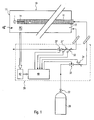
- the cryosurgical device comprises a fluid source 20 for providing a refrigerant 1 with a predetermined pressure.
- the refrigerant 1 is supplied via a temperature controller 30 of a cryoprobe 10.
- Inside the cryoprobe 10 runs an inlet 11, which directs the refrigerant 1 into a region near the probe tip 17.
- the refrigerant has a first pressure P 1 , which is so high that the resulting refrigerant-specific boiling point is significantly lower than the temperature present in the cryoprobe 10.
- the refrigerant 1 thus retains its liquid state of aggregation.
- the refrigerant 1 is discharged into an evaporation region 15 arranged inside the cryoprobe 10.
- the second pressure P 2 present here is significantly lower than the first pressure P 1 .
- refrigerant-specific results in a lower boiling point.
- the refrigerant 1 evaporates depending on the temperature present in the cryoprobe 10 and removes this heat energy.
- the refrigerant 1 may be supplied in gaseous form at maximum operating pressure (gas removal at the boiling line) such that the gas, upon cooling by the Joule-Thomson effect at the nozzle 14, converts to a two-phase mixture.
- the liquid fraction boils on the inner surface of the probe head or the probe tip 17 in the evaporation region 15.
- the refrigerant 1 or gas is then returned via a drain 12 within the cryoprobe 10 in the temperature controller 30 and disposed of there or recycled.
- the outlet 12 is in fluid communication with the evaporation area 15 and the temperature controller 30.
- the boiling temperature can be set according to a predetermined value. It is thus possible to establish a direct correlation between the second pressure P 2 and the cooling power of the cryoprobe 10.
- the temperature controller 30 comprises a controller 40 and a Zulaufdruckgregler 31, a drain pressure sensor 31 ', an inflow proportional valve 32, a flow proportional valve 32' and a flow sensor 33.
- the Zulaufdruckgregler 31 outputs signals that it Control 40 allow to close on the first pressure P 1 in the inlet 11.
- the inlet pressure sensor 31 is arranged on the inlet 11.
- the drain pressure sensor 31 ' is accordingly arranged on the drain 12 and outputs signals by means of which the controller 40 can determine the second pressure P 2 within the evaporation region 15.
- a pressure flow sensor 33 by means of which the controller 40 can close the present flow resistance is also located on the outlet 12.
- the controller 40 can correct the pressure measured by the discharge pressure sensor 31 taking into account the flow resistance and determine a correspondingly adjusted pressure P 2 .
- This correction is particularly important when the cryoprobe 10 is operated at low temperatures.
- the returning gas or the refrigerant 1 then has a very low pressure P 2 and thus a large specific volume, whereby a high flow resistance occurs.
- the boiling range of conventional refrigerants 1 is particularly steep and thus a small error in the calculation of the second pressure P 2 has a strong deviation in the adjustment of the temperature in the cryoprobe 10 result.
- the sensors and sensors for determining the first pressure P 1 and / or the second pressure P 2 need not be disposed in or near the evaporation region 15.
- cryoprobes 10 can be mounted in the drain 12 or inlet 11 or at its proximal end.
- a construction of cryoprobes 10 with a much smaller diameter is conceivable.
- the flow resistance can be determined solely on the basis of the inlet pressure sensor 31 and the outlet pressure sensor 31 '.
- device-specific data about the cryoprobe 10 connected to the temperature controller 30. These data include, for example, the cross-section of the nozzle 14.
- measurements of the flow resistance dependent be made of the first and / or second pressure P 1 , P 2 and tabulated.
- an exemplary embodiment comprises a data input device. This data input device has a memory for storing the device-specific data and a device recognition, which makes it possible to select a specific type of cryosensor 10. Once a particular cryoprobe 10 is selected, the controller 40 computes the device-specific flow resistance as a function of the pressure conditions and the stored device or instrument specific data.
- the data input device 42 may perform automatic detection of the attached device type.
- This automatic detection can take place, for example, by reading out a serial number which is stored in an RFID tag attached to the cryoprobe 10.
- cryoprobe 10 Numerous other methods should be known to the person skilled in the art how a corresponding identification of the connected cryoprobe 10 can be made possible. These include, inter alia, the determination of different parameters in a test phase of the cryoprobe 10 preceding an operation, the reading out of a Bluetooth tag or the scanning of a barcode.
- inventive method for controlling the temperature of the cryoprobe 10 can also be carried out when only a drain pressure sensor 31 'and a drain proportional valve 32' is present.
- the controller 40 can thus implement a control loop after the determination of the second pressure P 2 , in which the outflow proportional valve 32 ', which is connected to the outlet 12 is connected, is set so that the pressure P 2 reaches a predetermined value.
- This value corresponds depending on the refrigerant used 1 with a certain boiling or evaporation temperature. This temperature may be input to the controller 40 through an operating unit operated by the attending physician.
- the controller 40 can set the first pressure P 1 , which can be determined via the inlet pressure sensor 31, via the optional inlet proportional valve 32.
- the quantity of the refrigerant 1 introduced into the cryoprobe 10 can be regulated via the inlet proportional valve 32.
- the cooling capacity can be preset, which is achieved by means of the Joule-Thomson effect.
- the fluid source 20 also has an optional fluid source valve 22 that allows for manual adjustment of the inlet pressure at which the refrigerant 1 is introduced into the temperature controller 30.
- the invention sets the second pressure P 2 for controlling the cooling power of the cryoprobe 10.
- the specific boiling point of a refrigerant 1 is known to depend on the prevailing pressure and temperature. At a predetermined second pressure P 2, the refrigerant 1 thus boils only up to a specific temperature. As far as in the evaporation region 15 is already a lower temperature, the refrigerant does not boil 1. Accordingly, the system is not deprived of heat due to the change of state of matter. In the case of a continuous supply of refrigerant 1 at a constant second pressure P 2 , therefore, the corresponding specific temperature in the evaporation region 15 sets in.
Landscapes
- Health & Medical Sciences (AREA)
- Surgery (AREA)
- Life Sciences & Earth Sciences (AREA)
- Nuclear Medicine, Radiotherapy & Molecular Imaging (AREA)
- Medical Informatics (AREA)
- Engineering & Computer Science (AREA)
- Biomedical Technology (AREA)
- Heart & Thoracic Surgery (AREA)
- Otolaryngology (AREA)
- Molecular Biology (AREA)
- Animal Behavior & Ethology (AREA)
- General Health & Medical Sciences (AREA)
- Public Health (AREA)
- Veterinary Medicine (AREA)
- Surgical Instruments (AREA)
- Measuring Fluid Pressure (AREA)
- Thermotherapy And Cooling Therapy Devices (AREA)
Priority Applications (1)
| Application Number | Priority Date | Filing Date | Title |
|---|---|---|---|
| PL09772076T PL2339980T3 (pl) | 2008-07-02 | 2009-06-10 | Regulacja temperatury do kriosondy, urządzenie kriochirurgiczne z regulatorem temperatury i sposób regulacji temperatury kriosondy |
Applications Claiming Priority (3)
| Application Number | Priority Date | Filing Date | Title |
|---|---|---|---|
| DE102008031298 | 2008-07-02 | ||
| DE102008045563A DE102008045563B9 (de) | 2008-07-02 | 2008-09-03 | Temperaturregelung für eine Kryosonde, kryochirurgisches Gerät mit Temperaturregler und Verfahren zum Regeln der Temperatur einer Kryosonde |
| PCT/EP2009/004209 WO2010000376A1 (de) | 2008-07-02 | 2009-06-10 | Temperaturregelung für eine kryosonde, kryochirurgisches gerät mit temperaturregler und verfahren zum regeln der temperatur einer kryosonde |
Publications (2)
| Publication Number | Publication Date |
|---|---|
| EP2339980A1 EP2339980A1 (de) | 2011-07-06 |
| EP2339980B1 true EP2339980B1 (de) | 2014-07-16 |
Family
ID=41412921
Family Applications (1)
| Application Number | Title | Priority Date | Filing Date |
|---|---|---|---|
| EP09772076.7A Not-in-force EP2339980B1 (de) | 2008-07-02 | 2009-06-10 | Temperaturregelung für eine kryosonde, kryochirurgisches gerät mit temperaturregler und verfahren zum regeln der temperatur einer kryosonde |
Country Status (7)
| Country | Link |
|---|---|
| US (1) | US10485602B2 (pl) |
| EP (1) | EP2339980B1 (pl) |
| JP (1) | JP5619737B2 (pl) |
| CN (1) | CN102083383B (pl) |
| DE (1) | DE102008045563B9 (pl) |
| PL (1) | PL2339980T3 (pl) |
| WO (1) | WO2010000376A1 (pl) |
Families Citing this family (6)
| Publication number | Priority date | Publication date | Assignee | Title |
|---|---|---|---|---|
| WO2020018741A1 (en) * | 2018-07-20 | 2020-01-23 | Atricure, Inc. | Cryogenic surgical systems |
| US11633224B2 (en) | 2020-02-10 | 2023-04-25 | Icecure Medical Ltd. | Cryogen pump |
| DE102020123415B4 (de) * | 2020-09-08 | 2022-12-22 | Würth Elektronik GmbH & Co. KG | Tröpfchenweise digital gesteuertes Aufbringen einer kryogenen Flüssigkeit |
| US12426934B2 (en) | 2022-02-28 | 2025-09-30 | Icecure Medical Ltd. | Cryogen flow control |
| US12215811B2 (en) | 2022-07-18 | 2025-02-04 | Icecure Medical Ltd. | Cryogenic system connector |
| US12527613B2 (en) | 2023-09-11 | 2026-01-20 | Icecure Medical Ltd. | Cryoprobe |
Family Cites Families (13)
| Publication number | Priority date | Publication date | Assignee | Title |
|---|---|---|---|---|
| US5423807A (en) * | 1992-04-16 | 1995-06-13 | Implemed, Inc. | Cryogenic mapping and ablation catheter |
| GB2336782A (en) * | 1998-04-30 | 1999-11-03 | Spembly Medical Ltd | Cryosurgical apparatus |
| US6592577B2 (en) * | 1999-01-25 | 2003-07-15 | Cryocath Technologies Inc. | Cooling system |
| US6569158B1 (en) | 1999-01-25 | 2003-05-27 | Cryocath Technologies, Inc. | Leak detection system |
| US7004936B2 (en) * | 2000-08-09 | 2006-02-28 | Cryocor, Inc. | Refrigeration source for a cryoablation catheter |
| US6471694B1 (en) * | 2000-08-09 | 2002-10-29 | Cryogen, Inc. | Control system for cryosurgery |
| US6387092B1 (en) * | 1999-09-07 | 2002-05-14 | Scimed Life Systems, Inc. | Systems and methods to identify and disable re-used single use devices based on time elapsed from first therapeutic use |
| US6589234B2 (en) * | 2001-09-27 | 2003-07-08 | Cryocath Technologies Inc. | Cryogenic medical device with high pressure resistance tip |
| IL151486A0 (en) * | 2002-08-26 | 2003-04-10 | Levin Alexander | Cryosurgical instrument and its accessory system |
| US7357797B2 (en) * | 2004-06-30 | 2008-04-15 | Cryocor, Inc. | System and method for varying return pressure to control tip temperature of a cryoablation catheter |
| CN1935096A (zh) * | 2005-09-22 | 2007-03-28 | 上海导向医疗系统有限公司 | 一种氮气预冷节流肿瘤超低温治疗系统 |
| CN2868224Y (zh) * | 2005-12-26 | 2007-02-14 | 杨瑞森 | 设置冷冻探头的腔内可弯曲置入器 |
| US8187261B2 (en) * | 2008-05-29 | 2012-05-29 | Boston Scientific Scimed, Inc. | Regulating internal pressure of a cryotherapy balloon catheter |
-
2008
- 2008-09-03 DE DE102008045563A patent/DE102008045563B9/de not_active Expired - Fee Related
-
2009
- 2009-06-10 PL PL09772076T patent/PL2339980T3/pl unknown
- 2009-06-10 JP JP2011515155A patent/JP5619737B2/ja not_active Expired - Fee Related
- 2009-06-10 EP EP09772076.7A patent/EP2339980B1/de not_active Not-in-force
- 2009-06-10 CN CN200980125768.9A patent/CN102083383B/zh not_active Expired - Fee Related
- 2009-06-10 US US13/002,359 patent/US10485602B2/en not_active Expired - Fee Related
- 2009-06-10 WO PCT/EP2009/004209 patent/WO2010000376A1/de not_active Ceased
Also Published As
| Publication number | Publication date |
|---|---|
| EP2339980A1 (de) | 2011-07-06 |
| CN102083383B (zh) | 2014-04-09 |
| PL2339980T3 (pl) | 2014-12-31 |
| DE102008045563A1 (de) | 2010-01-14 |
| US10485602B2 (en) | 2019-11-26 |
| JP5619737B2 (ja) | 2014-11-05 |
| DE102008045563B4 (de) | 2011-01-05 |
| DE102008045563B9 (de) | 2012-01-26 |
| CN102083383A (zh) | 2011-06-01 |
| WO2010000376A1 (de) | 2010-01-07 |
| US20110152848A1 (en) | 2011-06-23 |
| JP2011526170A (ja) | 2011-10-06 |
Similar Documents
| Publication | Publication Date | Title |
|---|---|---|
| EP2339980B1 (de) | Temperaturregelung für eine kryosonde, kryochirurgisches gerät mit temperaturregler und verfahren zum regeln der temperatur einer kryosonde | |
| DE60306281T2 (de) | Kühlquelle für Kryoablationskatheter | |
| DE2831199B2 (de) | Kryochinirgiegerät | |
| EP2124025A1 (de) | Verfahren und Vorrichtung zum Füllen von Zielbehältern | |
| EP2160990B1 (de) | Versorgungsgerät mit Steuerung zum Betreiben einer Kryosonde, Kryochirurgisches Gerät | |
| DE102008038310B4 (de) | Kryochirurgisches Gerät zum Betreiben von Kryosonden, Verfahren zum Betreiben einer Kryosonde | |
| EP1671100A1 (de) | Kühleinrichtung zur kryokonservierung und entsprechendes bet riebsverfahren | |
| AT4855U2 (de) | Verfahren und vorrichtung zum behandeln von maische | |
| EP4058765B1 (de) | Verfahren zum ermitteln eines istwerts und/oder eines istwertbereichs wenigstens einer zustandsgrösse eines fluids in einer fluidströmung mittels wenigstens eines indikatorpartikels, verfahren zum betreiben einer fluidführenden einrichtung sowie einrichtung zum ermitteln des istwerts der wenigstens einen zustandsgrösse. | |
| WO2016055162A1 (de) | Verfahren zur regelung eines gekoppelten wärmetauscher-systems und wärmetauscher-system | |
| DE4126054C2 (de) | Kältemittel-Verbrauchsmeßsystem | |
| DE102023116363B4 (de) | Verfahren zur Bestimmung eines Siedepunkts eines flüssigen Stoffgemischs sowie Rotationsverdampfer mit einem Strömungssensor | |
| DE19729799A1 (de) | Verfahren zur Bestimmung des kalorischen Zustandes von Dampf, insbesondere zur Bestimmung der Dampfnässe von Naßdampf und Vorrichtung hierzu | |
| EP1039271A2 (de) | Füllstandsregelung für Flüssigkeiten in Druckbehältern | |
| DE102005061550A1 (de) | Verfahren zum Betreiben eines Abgasmassenstromsensors | |
| DE10025470B4 (de) | Verfahren und Vorrichtung zur Überprüfung der Durchlässigkeit von Leitungen | |
| EP3441529B1 (de) | Vorrichtung und verfahren zum gefrieren von erdreich | |
| DE19906772C1 (de) | Meßeinrichtung | |
| EP0321670A2 (de) | Vorrichtung zur Ansteuerung des Expansionsventils der Kälteeinrichtung bei einer Kraftfahrzeug-Klimaanlage | |
| DE102017123322A1 (de) | Verfahren zum Betreiben eines Gargeräts und Gargerät | |
| EP2960744B1 (de) | Volumenstrom- und temperaturregelung eines ausgangsfluidstroms | |
| DE1959041C3 (de) | Höhenstandsmesser für Flüssigkeiten | |
| DE19923241A1 (de) | Füllstandsregelung für Flüssigkeiten in Druckbehältern | |
| EP1410010A1 (de) | Verfahren und vorrichtung zur überwachung der stofflichen zusammensetzung von fluiden trennbaren medien | |
| DE2251627A1 (de) | Vorrichtung fuer die kryochirurgie |
Legal Events
| Date | Code | Title | Description |
|---|---|---|---|
| PUAI | Public reference made under article 153(3) epc to a published international application that has entered the european phase |
Free format text: ORIGINAL CODE: 0009012 |
|
| 17P | Request for examination filed |
Effective date: 20110201 |
|
| AK | Designated contracting states |
Kind code of ref document: A1 Designated state(s): AT BE BG CH CY CZ DE DK EE ES FI FR GB GR HR HU IE IS IT LI LT LU LV MC MK MT NL NO PL PT RO SE SI SK TR |
|
| AX | Request for extension of the european patent |
Extension state: AL BA RS |
|
| DAX | Request for extension of the european patent (deleted) | ||
| REG | Reference to a national code |
Ref country code: DE Ref legal event code: R079 Ref document number: 502009009660 Country of ref document: DE Free format text: PREVIOUS MAIN CLASS: A61B0018020000 Ipc: A61B0017000000 |
|
| GRAP | Despatch of communication of intention to grant a patent |
Free format text: ORIGINAL CODE: EPIDOSNIGR1 |
|
| RIC1 | Information provided on ipc code assigned before grant |
Ipc: A61B 17/00 20060101AFI20140204BHEP Ipc: A61B 18/02 20060101ALI20140204BHEP |
|
| INTG | Intention to grant announced |
Effective date: 20140220 |
|
| GRAS | Grant fee paid |
Free format text: ORIGINAL CODE: EPIDOSNIGR3 |
|
| GRAA | (expected) grant |
Free format text: ORIGINAL CODE: 0009210 |
|
| AK | Designated contracting states |
Kind code of ref document: B1 Designated state(s): AT BE BG CH CY CZ DE DK EE ES FI FR GB GR HR HU IE IS IT LI LT LU LV MC MK MT NL NO PL PT RO SE SI SK TR |
|
| REG | Reference to a national code |
Ref country code: GB Ref legal event code: FG4D Free format text: NOT ENGLISH |
|
| REG | Reference to a national code |
Ref country code: CH Ref legal event code: EP |
|
| REG | Reference to a national code |
Ref country code: IE Ref legal event code: FG4D Free format text: LANGUAGE OF EP DOCUMENT: GERMAN |
|
| REG | Reference to a national code |
Ref country code: AT Ref legal event code: REF Ref document number: 677055 Country of ref document: AT Kind code of ref document: T Effective date: 20140815 |
|
| REG | Reference to a national code |
Ref country code: DE Ref legal event code: R096 Ref document number: 502009009660 Country of ref document: DE Effective date: 20140828 |
|
| REG | Reference to a national code |
Ref country code: NL Ref legal event code: VDEP Effective date: 20140716 |
|
| REG | Reference to a national code |
Ref country code: LT Ref legal event code: MG4D |
|
| REG | Reference to a national code |
Ref country code: PL Ref legal event code: T3 |
|
| PG25 | Lapsed in a contracting state [announced via postgrant information from national office to epo] |
Ref country code: NO Free format text: LAPSE BECAUSE OF FAILURE TO SUBMIT A TRANSLATION OF THE DESCRIPTION OR TO PAY THE FEE WITHIN THE PRESCRIBED TIME-LIMIT Effective date: 20141016 Ref country code: ES Free format text: LAPSE BECAUSE OF FAILURE TO SUBMIT A TRANSLATION OF THE DESCRIPTION OR TO PAY THE FEE WITHIN THE PRESCRIBED TIME-LIMIT Effective date: 20140716 Ref country code: BG Free format text: LAPSE BECAUSE OF FAILURE TO SUBMIT A TRANSLATION OF THE DESCRIPTION OR TO PAY THE FEE WITHIN THE PRESCRIBED TIME-LIMIT Effective date: 20141016 Ref country code: PT Free format text: LAPSE BECAUSE OF FAILURE TO SUBMIT A TRANSLATION OF THE DESCRIPTION OR TO PAY THE FEE WITHIN THE PRESCRIBED TIME-LIMIT Effective date: 20141117 Ref country code: FI Free format text: LAPSE BECAUSE OF FAILURE TO SUBMIT A TRANSLATION OF THE DESCRIPTION OR TO PAY THE FEE WITHIN THE PRESCRIBED TIME-LIMIT Effective date: 20140716 Ref country code: SE Free format text: LAPSE BECAUSE OF FAILURE TO SUBMIT A TRANSLATION OF THE DESCRIPTION OR TO PAY THE FEE WITHIN THE PRESCRIBED TIME-LIMIT Effective date: 20140716 Ref country code: GR Free format text: LAPSE BECAUSE OF FAILURE TO SUBMIT A TRANSLATION OF THE DESCRIPTION OR TO PAY THE FEE WITHIN THE PRESCRIBED TIME-LIMIT Effective date: 20141017 Ref country code: LT Free format text: LAPSE BECAUSE OF FAILURE TO SUBMIT A TRANSLATION OF THE DESCRIPTION OR TO PAY THE FEE WITHIN THE PRESCRIBED TIME-LIMIT Effective date: 20140716 |
|
| PG25 | Lapsed in a contracting state [announced via postgrant information from national office to epo] |
Ref country code: CY Free format text: LAPSE BECAUSE OF FAILURE TO SUBMIT A TRANSLATION OF THE DESCRIPTION OR TO PAY THE FEE WITHIN THE PRESCRIBED TIME-LIMIT Effective date: 20140716 Ref country code: IS Free format text: LAPSE BECAUSE OF FAILURE TO SUBMIT A TRANSLATION OF THE DESCRIPTION OR TO PAY THE FEE WITHIN THE PRESCRIBED TIME-LIMIT Effective date: 20141116 Ref country code: NL Free format text: LAPSE BECAUSE OF FAILURE TO SUBMIT A TRANSLATION OF THE DESCRIPTION OR TO PAY THE FEE WITHIN THE PRESCRIBED TIME-LIMIT Effective date: 20140716 Ref country code: LV Free format text: LAPSE BECAUSE OF FAILURE TO SUBMIT A TRANSLATION OF THE DESCRIPTION OR TO PAY THE FEE WITHIN THE PRESCRIBED TIME-LIMIT Effective date: 20140716 |
|
| REG | Reference to a national code |
Ref country code: DE Ref legal event code: R097 Ref document number: 502009009660 Country of ref document: DE |
|
| PG25 | Lapsed in a contracting state [announced via postgrant information from national office to epo] |
Ref country code: DK Free format text: LAPSE BECAUSE OF FAILURE TO SUBMIT A TRANSLATION OF THE DESCRIPTION OR TO PAY THE FEE WITHIN THE PRESCRIBED TIME-LIMIT Effective date: 20140716 Ref country code: EE Free format text: LAPSE BECAUSE OF FAILURE TO SUBMIT A TRANSLATION OF THE DESCRIPTION OR TO PAY THE FEE WITHIN THE PRESCRIBED TIME-LIMIT Effective date: 20140716 Ref country code: CZ Free format text: LAPSE BECAUSE OF FAILURE TO SUBMIT A TRANSLATION OF THE DESCRIPTION OR TO PAY THE FEE WITHIN THE PRESCRIBED TIME-LIMIT Effective date: 20140716 Ref country code: SK Free format text: LAPSE BECAUSE OF FAILURE TO SUBMIT A TRANSLATION OF THE DESCRIPTION OR TO PAY THE FEE WITHIN THE PRESCRIBED TIME-LIMIT Effective date: 20140716 Ref country code: RO Free format text: LAPSE BECAUSE OF FAILURE TO SUBMIT A TRANSLATION OF THE DESCRIPTION OR TO PAY THE FEE WITHIN THE PRESCRIBED TIME-LIMIT Effective date: 20140716 |
|
| PLBE | No opposition filed within time limit |
Free format text: ORIGINAL CODE: 0009261 |
|
| STAA | Information on the status of an ep patent application or granted ep patent |
Free format text: STATUS: NO OPPOSITION FILED WITHIN TIME LIMIT |
|
| 26N | No opposition filed |
Effective date: 20150417 |
|
| PG25 | Lapsed in a contracting state [announced via postgrant information from national office to epo] |
Ref country code: SI Free format text: LAPSE BECAUSE OF FAILURE TO SUBMIT A TRANSLATION OF THE DESCRIPTION OR TO PAY THE FEE WITHIN THE PRESCRIBED TIME-LIMIT Effective date: 20140716 |
|
| PG25 | Lapsed in a contracting state [announced via postgrant information from national office to epo] |
Ref country code: MC Free format text: LAPSE BECAUSE OF FAILURE TO SUBMIT A TRANSLATION OF THE DESCRIPTION OR TO PAY THE FEE WITHIN THE PRESCRIBED TIME-LIMIT Effective date: 20140716 |
|
| REG | Reference to a national code |
Ref country code: CH Ref legal event code: PL |
|
| PG25 | Lapsed in a contracting state [announced via postgrant information from national office to epo] |
Ref country code: LU Free format text: LAPSE BECAUSE OF FAILURE TO SUBMIT A TRANSLATION OF THE DESCRIPTION OR TO PAY THE FEE WITHIN THE PRESCRIBED TIME-LIMIT Effective date: 20150610 |
|
| REG | Reference to a national code |
Ref country code: IE Ref legal event code: MM4A |
|
| PG25 | Lapsed in a contracting state [announced via postgrant information from national office to epo] |
Ref country code: IE Free format text: LAPSE BECAUSE OF NON-PAYMENT OF DUE FEES Effective date: 20150610 Ref country code: CH Free format text: LAPSE BECAUSE OF NON-PAYMENT OF DUE FEES Effective date: 20150630 Ref country code: LI Free format text: LAPSE BECAUSE OF NON-PAYMENT OF DUE FEES Effective date: 20150630 |
|
| REG | Reference to a national code |
Ref country code: FR Ref legal event code: PLFP Year of fee payment: 8 |
|
| REG | Reference to a national code |
Ref country code: AT Ref legal event code: MM01 Ref document number: 677055 Country of ref document: AT Kind code of ref document: T Effective date: 20150610 |
|
| PG25 | Lapsed in a contracting state [announced via postgrant information from national office to epo] |
Ref country code: AT Free format text: LAPSE BECAUSE OF NON-PAYMENT OF DUE FEES Effective date: 20150610 |
|
| PG25 | Lapsed in a contracting state [announced via postgrant information from national office to epo] |
Ref country code: MT Free format text: LAPSE BECAUSE OF FAILURE TO SUBMIT A TRANSLATION OF THE DESCRIPTION OR TO PAY THE FEE WITHIN THE PRESCRIBED TIME-LIMIT Effective date: 20140716 |
|
| PG25 | Lapsed in a contracting state [announced via postgrant information from national office to epo] |
Ref country code: HU Free format text: LAPSE BECAUSE OF FAILURE TO SUBMIT A TRANSLATION OF THE DESCRIPTION OR TO PAY THE FEE WITHIN THE PRESCRIBED TIME-LIMIT; INVALID AB INITIO Effective date: 20090610 |
|
| REG | Reference to a national code |
Ref country code: FR Ref legal event code: PLFP Year of fee payment: 9 |
|
| PG25 | Lapsed in a contracting state [announced via postgrant information from national office to epo] |
Ref country code: BE Free format text: LAPSE BECAUSE OF NON-PAYMENT OF DUE FEES Effective date: 20150630 Ref country code: HR Free format text: LAPSE BECAUSE OF FAILURE TO SUBMIT A TRANSLATION OF THE DESCRIPTION OR TO PAY THE FEE WITHIN THE PRESCRIBED TIME-LIMIT Effective date: 20140716 |
|
| PG25 | Lapsed in a contracting state [announced via postgrant information from national office to epo] |
Ref country code: TR Free format text: LAPSE BECAUSE OF FAILURE TO SUBMIT A TRANSLATION OF THE DESCRIPTION OR TO PAY THE FEE WITHIN THE PRESCRIBED TIME-LIMIT Effective date: 20140716 |
|
| PG25 | Lapsed in a contracting state [announced via postgrant information from national office to epo] |
Ref country code: MK Free format text: LAPSE BECAUSE OF FAILURE TO SUBMIT A TRANSLATION OF THE DESCRIPTION OR TO PAY THE FEE WITHIN THE PRESCRIBED TIME-LIMIT Effective date: 20140716 |
|
| REG | Reference to a national code |
Ref country code: FR Ref legal event code: PLFP Year of fee payment: 10 |
|
| PGFP | Annual fee paid to national office [announced via postgrant information from national office to epo] |
Ref country code: FR Payment date: 20200626 Year of fee payment: 12 |
|
| PGFP | Annual fee paid to national office [announced via postgrant information from national office to epo] |
Ref country code: PL Payment date: 20200522 Year of fee payment: 12 Ref country code: GB Payment date: 20200630 Year of fee payment: 12 Ref country code: IT Payment date: 20200618 Year of fee payment: 12 |
|
| PGFP | Annual fee paid to national office [announced via postgrant information from national office to epo] |
Ref country code: DE Payment date: 20200827 Year of fee payment: 12 |
|
| REG | Reference to a national code |
Ref country code: DE Ref legal event code: R119 Ref document number: 502009009660 Country of ref document: DE |
|
| GBPC | Gb: european patent ceased through non-payment of renewal fee |
Effective date: 20210610 |
|
| PG25 | Lapsed in a contracting state [announced via postgrant information from national office to epo] |
Ref country code: GB Free format text: LAPSE BECAUSE OF NON-PAYMENT OF DUE FEES Effective date: 20210610 Ref country code: DE Free format text: LAPSE BECAUSE OF NON-PAYMENT OF DUE FEES Effective date: 20220101 |
|
| PG25 | Lapsed in a contracting state [announced via postgrant information from national office to epo] |
Ref country code: FR Free format text: LAPSE BECAUSE OF NON-PAYMENT OF DUE FEES Effective date: 20210630 |
|
| PG25 | Lapsed in a contracting state [announced via postgrant information from national office to epo] |
Ref country code: IT Free format text: LAPSE BECAUSE OF NON-PAYMENT OF DUE FEES Effective date: 20210610 |
|
| PG25 | Lapsed in a contracting state [announced via postgrant information from national office to epo] |
Ref country code: PL Free format text: LAPSE BECAUSE OF NON-PAYMENT OF DUE FEES Effective date: 20210610 |