EP2339657B1 - Selbstführender piezoelektrischer Motor mit Radiallastfähigkeit - Google Patents
Selbstführender piezoelektrischer Motor mit Radiallastfähigkeit Download PDFInfo
- Publication number
- EP2339657B1 EP2339657B1 EP20100015702 EP10015702A EP2339657B1 EP 2339657 B1 EP2339657 B1 EP 2339657B1 EP 20100015702 EP20100015702 EP 20100015702 EP 10015702 A EP10015702 A EP 10015702A EP 2339657 B1 EP2339657 B1 EP 2339657B1
- Authority
- EP
- European Patent Office
- Prior art keywords
- piezoelectric actuator
- push rod
- piezoelectric
- piezoelectric motor
- axial
- Prior art date
- Legal status (The legal status is an assumption and is not a legal conclusion. Google has not performed a legal analysis and makes no representation as to the accuracy of the status listed.)
- Not-in-force
Links
Images


Classifications
-
- H—ELECTRICITY
- H02—GENERATION; CONVERSION OR DISTRIBUTION OF ELECTRIC POWER
- H02N—ELECTRIC MACHINES NOT OTHERWISE PROVIDED FOR
- H02N2/00—Electric machines in general using piezoelectric effect, electrostriction or magnetostriction
- H02N2/02—Electric machines in general using piezoelectric effect, electrostriction or magnetostriction producing linear motion, e.g. actuators; Linear positioners ; Linear motors
- H02N2/04—Constructional details
Definitions
- the present invention refers to a self-guided piezoelectric motor with radial load capability.
- a piezoelectric actuator is a device composed of a plurality of ceramic disks stacked to form a cylinder, between such ceramic disks being interposed disks whose thickness is a few micrometers that are the electrodes: such actuators are generally used in industrial applications such as micro-positioning, active vibration check, etc.
- the particular structure of the piezoelectric actuator makes this latter one subjected to numerous inconveniences: in fact, it is able to resist only to compression loads, while in practice it has no way of supporting traction and shearing loads, bending or twisting moments.
- the art proposes motors composed of a piezoelectric actuator lined into a container where there is a device for pre-loading, typically springs.
- US-A-5 359 252 discloses a piezoelectric motor according to the preamble of Claim 1.
- object of the present invention is solving the above prior art problems, by providing a self-guided piezoelectric motor with radial load capability equipped with all mechanical systems necessary for its operation.
- a further object of the present invention is providing a self-guided piezoelectric motor that allows a static micropositioning and/or operating under frequency in terms of imposed displacements / speeds / accelerations, being able to operate on the system on which it is implemented with high axial forces, also supporting shearing actions / forces such as, for example, radial actions.
- Another object of the present invention is providing a compact self-guided piezoelectric motor with radial load capability that does not require further mechanical arrangements in order to operate, consequently resulting self-sufficient and capable of being directly used as linear motor.
- a further object of the present invention is providing a self-guided piezoelectric motor equipped with high static stiffness intrinsic in all directions.
- Another object of the present invention is providing a self-guided piezoelectric motor capable of supporting not only axial loads but also shearing loads, bending and twisting moments.
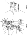
- the self-guided piezoelectric motor 1 with radial load capability is composed of at least one piezoelectric actuator 3 contained inside at least one container 5, inside which there are provided, as will be described below in more detail, all elements capable of axially pre-loading the actuator 3 itself, of avoiding traction loads for this latter one and of filtering shearing loads and external moments acting thereon.
- the piezoelectric actuator 3 is of a substantially known type, being composed of a plurality of ceramic disks stacked to form a cylinder, between such ceramic disks being inteprosed disks whose thickness is equal to a few micrometers, that are the electrodes thereof.
- the container 5 is composed of a side perimeter wall 5a, to which at least one base 5b is mechanically fastened thereto on its bottom, such piezoelectric actuator 3 being interfaced with the external environment, and in particular with the external system to be actuated, by interposing at least one radial supporting element 7 axially moving along a reference axis R-R defining an actuation direction of the piezoelectric actuator 3 and connected to the container 5 to guarantee a high radial, flexural and torsional stiffness, and a low axial stiffness.
- the axially-moving radial supporting element 7 is composed of at least one push rod 9 axially moving with respect to such reference axis R-R under the action of the piezoelectric actuator 3 having a first end 9a in contact with at least one first end 3a of the piezoelectric actuator 3 and a second end 9b, possibly equipped with at least one fastening seat 9c with internal threading, aimed to connect the motor 1 according to the present invention to the external system to be actuated, such push rod 9 being radially equipped with axial guiding means with respect to the reference axis R-R mechanically connected to the container 5, and in particular to the side perimeter wall 5a in an opposite position to the base 5b through the most adequate fastening means such as, for example, screws 13 and a respective closing cover 14.
- the axial guiding means comprise at least one flexural disk 11 coaxial with respect to the reference axis R-R (preferably the push rod 9 is equipped with at least two flexural disks 11, concentric and coaxial with respect to the reference axis R-R) mechanically connected to the container 5, and in particular to the side perimeter wall 5a in an opposite position to the base 5b; the container 5 therefore operates also as support for the flexural disks 11 that, preferably, form a single body with the push rod 9: the axial movement of the push rod 9 with respect to the reference axis R-R under the action of the piezoelectric actuator 3 is then guided by the flexural disks 11 that, having a high radial, flexural and torsional stiffness, and a low axial stiffness, perform a mechanical filtering function, supporting the respective force components, letting only a very small percentage thereof enter the piezoelectric actuator 3, in order to prevent its breaking.
- the guiding means could also comprise even only one or more flexural blades with circular sector, radially arranged on the push rod 9 with respect to the reference axis R-R as replacement of the complete flexural disk 11, without thereby departing from the scope of the present invention as defined in the claims.
- the axially-moving radial supporting element 7, and in particular the flexural disks 11, in addition to allow the above filtering of the loads, apart from the axial one, can be used to pre-load the piezoelectric actuator 3 in order to allow this latter one to operate under traction.
- the axially-moving radial supporting element 7 is equipped with one or more sensors, preferably of the "strain-gauge” type or the “piezo-film” type, for measuring the micrometric axial displacement of the push rod 9: preferably, the sensors are applied, for example by gluing or other known deposition technique, on the upper and/or lower surface of the flexural disks 11, in such a way as to measure the distortion of the disk 11 itself that is related to the displacement of the push rod 9.
- mechanical uncoupling means can be interposed between a second end 3a of such piezoelectric actuator 3 and the base 5b of the container 5.
- such mechanical uncoupling means can be composed of at least one layer of friction-preventing material 15.
- such mechanical uncoupling means can be composed of at least one ball joint 17 composed of at least one oscillation ball 17a connected to the second end 3b of the piezoelectric actuator 3 and oscillating inside a respective seat 17b of the base 5b of the container 5.
- such mechanical uncoupling means can be composed of at least one axial bearing 18 suitable for filtering twisting moments and shearing action.
- the piezoelectric actuator 3 can be of a type internally equipped with at least one axial recess 19 adapted to allow an adjustment of the axial height of the push rod 9 that is necessary, for example, every time the push rod 9 must have a certain engagement/disengagement stroke that allows it, when it is not actuated by the piezoelectric actuator 3, to be manually taken in contact with a certain piece of the external system to be actuated: such application can for example deal with active blocking/tightening systems for workpieces that must be worked with machine tools.
- the push rod 9 can be equipped with at least one axially-moving stem 21 that can slide, possibly with a screwing/unscrewing movement, inside the axial recess 19 of the piezoelectric actuator 3. Therefore, once having reached the desired axial position, the axially-moving stem 21 can be made integral with the piezoelectric actuator 3 and the rest of the push rod 9, and in particular the flexural disks 11, through suitable fastening means, preferably composed of at least one elastic tightening pliers 23 coaxially arranged onto the stem 21 and interfering with a suitable seat 24 of the push rod 9 that is manually tightened into such seat 24 through at least one tightening ring nut 25, also coaxially arranged onto the stem 21, preferably catching a corresponding threaded seat of the push rod 9.
- suitable fastening means preferably composed of at least one elastic tightening pliers 23 coaxially arranged onto the stem 21 and interfering with a suitable seat 24 of the push rod 9 that is manually tightened into such seat 24 through at least
- the second end 9b of the push rod 9 can be connected, for example by screwing into the fastening seat 9c, to at least one accessory functional element, such as for example a pliers 27 for blocking/fastening a piece 29 for which an active position chesk is desired.
- accessory functional element such as for example a pliers 27 for blocking/fastening a piece 29 for which an active position chesk is desired.
- the self-guided piezoelectric motor 1 with radial load capability is a self-sufficient mechanical system, namely capable of resisting to external loads, that can be directly installed on the external system to be actuated without the need of providing particular arrangements for safeguarding the integrity of the piezoelectric actuator 3 contained therein.
Landscapes
- General Electrical Machinery Utilizing Piezoelectricity, Electrostriction Or Magnetostriction (AREA)
Claims (8)
- Selbstgesteuerter piezoelektrischer Motor (1) mit radialer Lastkapazität, der aus mindestens einem piezoelektrischem Antrieb (3) besteht, welcher in mindestens einem Gehäuse (5) enthalten ist, der genannte piezoelektrische Antrieb (3) ist mit einem externen System verbunden, das durch das Dazwischenlegen von mindestens einem radialen Trägerelement (7) angetrieben wird, welches axial längs einer Bezugsachse (R-R) beweglich ist, die eine Antriebsrichtung des genannten piezoelektrischen Antriebs (3) definiert, das genannte radiale axial bewegliche Trägerelement (7) besteht aus mindestens einem Stößelschaft (9), der durch die Einwirkung des genannten piezoelektrischen Antriebs (3) axial beweglich zur genannten Bezugsachse (R-R) ist, der genannte Stößelschaft (9) ist radial mit axialen Steuervorrichtungen zur genannten Bezugsachse (R-R) ausgestattet, die mechanisch mit dem genannten Gehäuse (5) verbunden sind, und ist dadurch gekennzeichnet, dass das genannte radiale axial bewegliche Trägerelement (7) mit einem oder mehreren Sensoren ausgestattet ist, die dazu dienen, eine mikrometrische Axialverschiebung des genannten Stößelschaftes (9) zu messen.
- Piezoelektrischer Motor (1) gemäß Patentanspruch 1, der dadurch gekennzeichnet ist, dass die axialen Steuervorrichtungen mindestens eine koaxiale Biegescheibe (11) zur genannten Bezugsachse (R-R) einschließen.
- Piezoelektrischer Motor (1) gemäß Patentanspruch 1, der dadurch gekennzeichnet ist, dass der genannte Stößelschaft (9) ein erstes Endstück (9a) hat, das mit mindestens einem ersten Endstück (3a) des genannten piezoelektrischen Antriebs (3) verbunden ist, sowie ein zweites Endstück (9b), das mit dem genannten externen System verbunden ist, welches angetrieben werden soll.
- Piezoelektrischer Motor (1) gemäß Patentanspruch 1, der dadurch gekennzeichnet ist, dass zwischen dem genannten zweiten Endstück (3a) des genannten piezoelektrischen Antriebs (3) und einer Basis (5b) des genannten Gehäuses (5) mechanische Entkopplungsvorrichtungen angebracht wurden.
- Piezoelektrischer Motor (1) gemäß Patentanspruch 4, der dadurch gekennzeichnet ist, dass die genannten Entkopplungsvorrichtungen aus mindestens einer Schicht aus Antifriktionsmaterial (13) oder aus mindestens einem Kugelgelenk (17) bestehen, das aus mindestens einer Schwingkugel (17a) besteht, die mit dem genannten zweiten Endstück (3b) des genannten piezoelektrischen Antriebs (3) verbunden ist und in einer entsprechenden Aufnahme (17b) der genannten Basis (5b) schwingt, oder aus mindestens einem Axiallager (18).
- Piezoelektrischer Motor (1) gemäß Patentanspruch 1, der dadurch gekennzeichnet ist, dass der genannte piezoelektrische Antrieb (3) intern mit mindestens einem Axialhohlraum (19) ausgestattet ist, der dazu dient, eine Axialhöhenverstellung des genannten Stößelschaftes (9) zu ermöglichen.
- Piezoelektrischer Motor (1) gemäß Patentanspruch 6, der dadurch gekennzeichnet ist, dass der genannte Stößelschaft (9) mit mindestens einem axial beweglichen Schaft (21) ausgestattet ist, der im genannten Axialhohlraum (19) verschoben wird, welcher durch Befestigungsvorrichtungen, die aus mindestens einer elastischen Spannzange (23) bestehen, welche durch mindestens eine Spannmutter (25) gespannt wird, ein Stück mit dem genannten piezoelektrischen Antrieb (3) und dem genannten Stößelschaft (9) bildet.
- Piezoelektrischer Motor (1) gemäß Patentanspruch 3, der dadurch gekennzeichnet ist, dass das genannte zweite Endstück (9b) des genannten Stößelschaftes (9) mit mindestens einem zusätzlichen Funktionselement (27) verbunden ist.
Applications Claiming Priority (1)
| Application Number | Priority Date | Filing Date | Title |
|---|---|---|---|
| IT001037A ITTO20091037A1 (it) | 2009-12-24 | 2009-12-24 | Motore piezoelettrico autoguidato con capacita' di carico radiale |
Publications (2)
| Publication Number | Publication Date |
|---|---|
| EP2339657A1 EP2339657A1 (de) | 2011-06-29 |
| EP2339657B1 true EP2339657B1 (de) | 2012-07-11 |
Family
ID=42321124
Family Applications (1)
| Application Number | Title | Priority Date | Filing Date |
|---|---|---|---|
| EP20100015702 Not-in-force EP2339657B1 (de) | 2009-12-24 | 2010-12-16 | Selbstführender piezoelektrischer Motor mit Radiallastfähigkeit |
Country Status (2)
| Country | Link |
|---|---|
| EP (1) | EP2339657B1 (de) |
| IT (1) | ITTO20091037A1 (de) |
Families Citing this family (1)
| Publication number | Priority date | Publication date | Assignee | Title |
|---|---|---|---|---|
| CN114244182B (zh) * | 2021-12-25 | 2023-10-24 | 西安交通大学 | 含力与位移双传感的直线式压电作动器及其作动方法 |
Family Cites Families (4)
| Publication number | Priority date | Publication date | Assignee | Title |
|---|---|---|---|---|
| DD119141A1 (de) * | 1974-10-04 | 1976-04-12 | ||
| US5359252A (en) * | 1993-03-30 | 1994-10-25 | The United States Of America As Represented By The United States Department Of Energy | Lead magnesium niobate actuator for micropositioning |
| US7307371B2 (en) * | 2005-11-18 | 2007-12-11 | Delphi Technologies, Inc. | Actuator with amplified stroke length |
| DE102006032743A1 (de) * | 2006-07-14 | 2008-01-17 | Robert Bosch Gmbh | Aktor zum Hubantrieb eines Stellglieds |
-
2009
- 2009-12-24 IT IT001037A patent/ITTO20091037A1/it unknown
-
2010
- 2010-12-16 EP EP20100015702 patent/EP2339657B1/de not_active Not-in-force
Also Published As
| Publication number | Publication date |
|---|---|
| ITTO20091037A1 (it) | 2010-03-25 |
| EP2339657A1 (de) | 2011-06-29 |
Similar Documents
| Publication | Publication Date | Title |
|---|---|---|
| US10967528B2 (en) | Maintenance jig for balancer of robot | |
| CN110682326B (zh) | 水平多关节机器人 | |
| JP5541550B2 (ja) | 射出成形機の型締装置 | |
| EP3054175B1 (de) | Tellerfedermutternplatte | |
| KR20250157319A (ko) | 일체형 힘 측정부를 갖는 볼 스크루 조립체 | |
| EP2835541B1 (de) | Nicht klappernde Hülse für eine Gelenkverbindung | |
| CN103890414A (zh) | 具有防护元件和至少一个热和振荡解耦紧固装置的防护装置 | |
| DK3180550T3 (en) | Sealing device with damping joints | |
| EP2339657B1 (de) | Selbstführender piezoelektrischer Motor mit Radiallastfähigkeit | |
| US5761963A (en) | Spindle nut/threaded spindle device | |
| EP3104021B1 (de) | Hochschwingende pneumatische kolbenanordnung aus additiver fertigung | |
| JP4667222B2 (ja) | クラッチカバー組立体 | |
| US10539196B2 (en) | Selectable one-way clutch | |
| JP6051802B2 (ja) | クラッチ装置 | |
| US7434486B2 (en) | Lead screw bearing | |
| JP4170342B2 (ja) | アクチュエータの偏向伝達装置 | |
| US10933525B2 (en) | Horizontal articulated robot | |
| US12535096B2 (en) | Threaded fastener for a fastening element, fastening rail for an aircraft cabin, and aircraft provided therewith | |
| US10900549B2 (en) | Mechatronic system with shock absorber | |
| US7818988B2 (en) | Striker plate and sheet-metal forming tool comprising such a striker plate | |
| AU2023286341A1 (en) | Vibration isolator with hard friction bushing | |
| CN113330681A (zh) | 机电线性驱动器 | |
| JPH04229513A (ja) | 高電圧装置 | |
| JPH11125216A (ja) | 位置決め具 | |
| JPH0317631B2 (de) |
Legal Events
| Date | Code | Title | Description |
|---|---|---|---|
| PUAI | Public reference made under article 153(3) epc to a published international application that has entered the european phase |
Free format text: ORIGINAL CODE: 0009012 |
|
| AK | Designated contracting states |
Kind code of ref document: A1 Designated state(s): AL AT BE BG CH CY CZ DE DK EE ES FI FR GB GR HR HU IE IS IT LI LT LU LV MC MK MT NL NO PL PT RO RS SE SI SK SM TR |
|
| AX | Request for extension of the european patent |
Extension state: BA ME |
|
| REG | Reference to a national code |
Ref country code: DE Ref legal event code: R079 Ref document number: 602010002125 Country of ref document: DE Free format text: PREVIOUS MAIN CLASS: H01L0041053000 Ipc: H02N0002000000 |
|
| 17P | Request for examination filed |
Effective date: 20111212 |
|
| GRAP | Despatch of communication of intention to grant a patent |
Free format text: ORIGINAL CODE: EPIDOSNIGR1 |
|
| RIC1 | Information provided on ipc code assigned before grant |
Ipc: H02N 2/04 20060101ALI20120117BHEP Ipc: H02N 2/00 20060101AFI20120117BHEP |
|
| RIN1 | Information on inventor provided before grant (corrected) |
Inventor name: MERLO, ANGELO Inventor name: RICCIARDI, DONATO Inventor name: TADDEI, FRANCO |
|
| GRAS | Grant fee paid |
Free format text: ORIGINAL CODE: EPIDOSNIGR3 |
|
| GRAA | (expected) grant |
Free format text: ORIGINAL CODE: 0009210 |
|
| AK | Designated contracting states |
Kind code of ref document: B1 Designated state(s): AL AT BE BG CH CY CZ DE DK EE ES FI FR GB GR HR HU IE IS IT LI LT LU LV MC MK MT NL NO PL PT RO RS SE SI SK SM TR |
|
| REG | Reference to a national code |
Ref country code: GB Ref legal event code: FG4D |
|
| REG | Reference to a national code |
Ref country code: CH Ref legal event code: EP |
|
| REG | Reference to a national code |
Ref country code: AT Ref legal event code: REF Ref document number: 566559 Country of ref document: AT Kind code of ref document: T Effective date: 20120715 |
|
| REG | Reference to a national code |
Ref country code: IE Ref legal event code: FG4D |
|
| REG | Reference to a national code |
Ref country code: DE Ref legal event code: R096 Ref document number: 602010002125 Country of ref document: DE Effective date: 20120906 |
|
| REG | Reference to a national code |
Ref country code: NL Ref legal event code: VDEP Effective date: 20120711 |
|
| REG | Reference to a national code |
Ref country code: AT Ref legal event code: MK05 Ref document number: 566559 Country of ref document: AT Kind code of ref document: T Effective date: 20120711 |
|
| REG | Reference to a national code |
Ref country code: LT Ref legal event code: MG4D Effective date: 20120711 |
|
| PG25 | Lapsed in a contracting state [announced via postgrant information from national office to epo] |
Ref country code: IS Free format text: LAPSE BECAUSE OF FAILURE TO SUBMIT A TRANSLATION OF THE DESCRIPTION OR TO PAY THE FEE WITHIN THE PRESCRIBED TIME-LIMIT Effective date: 20121111 Ref country code: HR Free format text: LAPSE BECAUSE OF FAILURE TO SUBMIT A TRANSLATION OF THE DESCRIPTION OR TO PAY THE FEE WITHIN THE PRESCRIBED TIME-LIMIT Effective date: 20120711 Ref country code: CY Free format text: LAPSE BECAUSE OF FAILURE TO SUBMIT A TRANSLATION OF THE DESCRIPTION OR TO PAY THE FEE WITHIN THE PRESCRIBED TIME-LIMIT Effective date: 20120711 Ref country code: LT Free format text: LAPSE BECAUSE OF FAILURE TO SUBMIT A TRANSLATION OF THE DESCRIPTION OR TO PAY THE FEE WITHIN THE PRESCRIBED TIME-LIMIT Effective date: 20120711 Ref country code: FI Free format text: LAPSE BECAUSE OF FAILURE TO SUBMIT A TRANSLATION OF THE DESCRIPTION OR TO PAY THE FEE WITHIN THE PRESCRIBED TIME-LIMIT Effective date: 20120711 Ref country code: BE Free format text: LAPSE BECAUSE OF FAILURE TO SUBMIT A TRANSLATION OF THE DESCRIPTION OR TO PAY THE FEE WITHIN THE PRESCRIBED TIME-LIMIT Effective date: 20120711 Ref country code: AT Free format text: LAPSE BECAUSE OF FAILURE TO SUBMIT A TRANSLATION OF THE DESCRIPTION OR TO PAY THE FEE WITHIN THE PRESCRIBED TIME-LIMIT Effective date: 20120711 Ref country code: NO Free format text: LAPSE BECAUSE OF FAILURE TO SUBMIT A TRANSLATION OF THE DESCRIPTION OR TO PAY THE FEE WITHIN THE PRESCRIBED TIME-LIMIT Effective date: 20121011 |
|
| PG25 | Lapsed in a contracting state [announced via postgrant information from national office to epo] |
Ref country code: SE Free format text: LAPSE BECAUSE OF FAILURE TO SUBMIT A TRANSLATION OF THE DESCRIPTION OR TO PAY THE FEE WITHIN THE PRESCRIBED TIME-LIMIT Effective date: 20120711 Ref country code: LV Free format text: LAPSE BECAUSE OF FAILURE TO SUBMIT A TRANSLATION OF THE DESCRIPTION OR TO PAY THE FEE WITHIN THE PRESCRIBED TIME-LIMIT Effective date: 20120711 Ref country code: SI Free format text: LAPSE BECAUSE OF FAILURE TO SUBMIT A TRANSLATION OF THE DESCRIPTION OR TO PAY THE FEE WITHIN THE PRESCRIBED TIME-LIMIT Effective date: 20120711 Ref country code: PT Free format text: LAPSE BECAUSE OF FAILURE TO SUBMIT A TRANSLATION OF THE DESCRIPTION OR TO PAY THE FEE WITHIN THE PRESCRIBED TIME-LIMIT Effective date: 20121112 Ref country code: GR Free format text: LAPSE BECAUSE OF FAILURE TO SUBMIT A TRANSLATION OF THE DESCRIPTION OR TO PAY THE FEE WITHIN THE PRESCRIBED TIME-LIMIT Effective date: 20121012 Ref country code: PL Free format text: LAPSE BECAUSE OF FAILURE TO SUBMIT A TRANSLATION OF THE DESCRIPTION OR TO PAY THE FEE WITHIN THE PRESCRIBED TIME-LIMIT Effective date: 20120711 |
|
| PG25 | Lapsed in a contracting state [announced via postgrant information from national office to epo] |
Ref country code: NL Free format text: LAPSE BECAUSE OF FAILURE TO SUBMIT A TRANSLATION OF THE DESCRIPTION OR TO PAY THE FEE WITHIN THE PRESCRIBED TIME-LIMIT Effective date: 20120711 |
|
| PG25 | Lapsed in a contracting state [announced via postgrant information from national office to epo] |
Ref country code: ES Free format text: LAPSE BECAUSE OF FAILURE TO SUBMIT A TRANSLATION OF THE DESCRIPTION OR TO PAY THE FEE WITHIN THE PRESCRIBED TIME-LIMIT Effective date: 20121022 Ref country code: CZ Free format text: LAPSE BECAUSE OF FAILURE TO SUBMIT A TRANSLATION OF THE DESCRIPTION OR TO PAY THE FEE WITHIN THE PRESCRIBED TIME-LIMIT Effective date: 20120711 Ref country code: RO Free format text: LAPSE BECAUSE OF FAILURE TO SUBMIT A TRANSLATION OF THE DESCRIPTION OR TO PAY THE FEE WITHIN THE PRESCRIBED TIME-LIMIT Effective date: 20120711 Ref country code: DK Free format text: LAPSE BECAUSE OF FAILURE TO SUBMIT A TRANSLATION OF THE DESCRIPTION OR TO PAY THE FEE WITHIN THE PRESCRIBED TIME-LIMIT Effective date: 20120711 Ref country code: EE Free format text: LAPSE BECAUSE OF FAILURE TO SUBMIT A TRANSLATION OF THE DESCRIPTION OR TO PAY THE FEE WITHIN THE PRESCRIBED TIME-LIMIT Effective date: 20120711 |
|
| PLBE | No opposition filed within time limit |
Free format text: ORIGINAL CODE: 0009261 |
|
| STAA | Information on the status of an ep patent application or granted ep patent |
Free format text: STATUS: NO OPPOSITION FILED WITHIN TIME LIMIT |
|
| PG25 | Lapsed in a contracting state [announced via postgrant information from national office to epo] |
Ref country code: SK Free format text: LAPSE BECAUSE OF FAILURE TO SUBMIT A TRANSLATION OF THE DESCRIPTION OR TO PAY THE FEE WITHIN THE PRESCRIBED TIME-LIMIT Effective date: 20120711 |
|
| 26N | No opposition filed |
Effective date: 20130412 |
|
| PG25 | Lapsed in a contracting state [announced via postgrant information from national office to epo] |
Ref country code: RS Free format text: LAPSE BECAUSE OF FAILURE TO SUBMIT A TRANSLATION OF THE DESCRIPTION OR TO PAY THE FEE WITHIN THE PRESCRIBED TIME-LIMIT Effective date: 20120711 Ref country code: MC Free format text: LAPSE BECAUSE OF NON-PAYMENT OF DUE FEES Effective date: 20121231 Ref country code: BG Free format text: LAPSE BECAUSE OF FAILURE TO SUBMIT A TRANSLATION OF THE DESCRIPTION OR TO PAY THE FEE WITHIN THE PRESCRIBED TIME-LIMIT Effective date: 20121011 |
|
| REG | Reference to a national code |
Ref country code: DE Ref legal event code: R097 Ref document number: 602010002125 Country of ref document: DE Effective date: 20130412 |
|
| REG | Reference to a national code |
Ref country code: IE Ref legal event code: MM4A |
|
| REG | Reference to a national code |
Ref country code: FR Ref legal event code: ST Effective date: 20130830 |
|
| PG25 | Lapsed in a contracting state [announced via postgrant information from national office to epo] |
Ref country code: IE Free format text: LAPSE BECAUSE OF NON-PAYMENT OF DUE FEES Effective date: 20121216 |
|
| PG25 | Lapsed in a contracting state [announced via postgrant information from national office to epo] |
Ref country code: FR Free format text: LAPSE BECAUSE OF NON-PAYMENT OF DUE FEES Effective date: 20130102 Ref country code: AL Free format text: LAPSE BECAUSE OF FAILURE TO SUBMIT A TRANSLATION OF THE DESCRIPTION OR TO PAY THE FEE WITHIN THE PRESCRIBED TIME-LIMIT Effective date: 20120711 Ref country code: MT Free format text: LAPSE BECAUSE OF FAILURE TO SUBMIT A TRANSLATION OF THE DESCRIPTION OR TO PAY THE FEE WITHIN THE PRESCRIBED TIME-LIMIT Effective date: 20120711 |
|
| PG25 | Lapsed in a contracting state [announced via postgrant information from national office to epo] |
Ref country code: TR Free format text: LAPSE BECAUSE OF FAILURE TO SUBMIT A TRANSLATION OF THE DESCRIPTION OR TO PAY THE FEE WITHIN THE PRESCRIBED TIME-LIMIT Effective date: 20120711 |
|
| PG25 | Lapsed in a contracting state [announced via postgrant information from national office to epo] |
Ref country code: LU Free format text: LAPSE BECAUSE OF NON-PAYMENT OF DUE FEES Effective date: 20121216 Ref country code: SM Free format text: LAPSE BECAUSE OF FAILURE TO SUBMIT A TRANSLATION OF THE DESCRIPTION OR TO PAY THE FEE WITHIN THE PRESCRIBED TIME-LIMIT Effective date: 20120711 |
|
| PG25 | Lapsed in a contracting state [announced via postgrant information from national office to epo] |
Ref country code: HU Free format text: LAPSE BECAUSE OF FAILURE TO SUBMIT A TRANSLATION OF THE DESCRIPTION OR TO PAY THE FEE WITHIN THE PRESCRIBED TIME-LIMIT Effective date: 20101216 |
|
| PG25 | Lapsed in a contracting state [announced via postgrant information from national office to epo] |
Ref country code: MK Free format text: LAPSE BECAUSE OF FAILURE TO SUBMIT A TRANSLATION OF THE DESCRIPTION OR TO PAY THE FEE WITHIN THE PRESCRIBED TIME-LIMIT Effective date: 20120711 |
|
| REG | Reference to a national code |
Ref country code: CH Ref legal event code: PL |
|
| GBPC | Gb: european patent ceased through non-payment of renewal fee |
Effective date: 20141216 |
|
| PG25 | Lapsed in a contracting state [announced via postgrant information from national office to epo] |
Ref country code: LI Free format text: LAPSE BECAUSE OF NON-PAYMENT OF DUE FEES Effective date: 20141231 Ref country code: CH Free format text: LAPSE BECAUSE OF NON-PAYMENT OF DUE FEES Effective date: 20141231 Ref country code: GB Free format text: LAPSE BECAUSE OF NON-PAYMENT OF DUE FEES Effective date: 20141216 |
|
| PGFP | Annual fee paid to national office [announced via postgrant information from national office to epo] |
Ref country code: IT Payment date: 20151221 Year of fee payment: 6 |
|
| PG25 | Lapsed in a contracting state [announced via postgrant information from national office to epo] |
Ref country code: IT Free format text: LAPSE BECAUSE OF NON-PAYMENT OF DUE FEES Effective date: 20161216 |
|
| PGFP | Annual fee paid to national office [announced via postgrant information from national office to epo] |
Ref country code: DE Payment date: 20171222 Year of fee payment: 8 |
|
| REG | Reference to a national code |
Ref country code: DE Ref legal event code: R119 Ref document number: 602010002125 Country of ref document: DE |
|
| PG25 | Lapsed in a contracting state [announced via postgrant information from national office to epo] |
Ref country code: DE Free format text: LAPSE BECAUSE OF NON-PAYMENT OF DUE FEES Effective date: 20190702 |